raph sets - radionerds war department washington 25, d. c., is june 1945 tm 11-351, telegraph sets...
TRANSCRIPT

li li o
WAR DEPARTME~ CHNICAL MANUAL -IJ/13
TRill: i! SI I f 1-;; ,
RAPH SETS -5, TG-5-A, AND TG-5-B
WARNING: no. _ """ ,...... "'" .. 1>1'" ",,,"Of af thk ." .. u."." ...... o... .. _.~ . .... II 10 " ..... _ "lot,,, "'0" 7 Sr •• , ....... , ..... <ht~Ioo. .... .......... , .. ,."J,,~ .. iI' .... V ....
! i ;v," hi'.' ..... II ,
....... ! I :;q ....
ni,AHY
NOV 5 1948
i;,~, .. ,,,,,,
WAR D EPARTM EN T. J UNE 1945 /
,
,

W~ R D EP~RTMENT TEC H N I C~L M~NU AL TM 11-351
ni.r "",,,,,,,/ svp"udu TAIl I - 35I , 22 S,p'~",1Mr 1941, ,'NdMd;N/I C 1, 2J I a"~llf'y 1IHl, Cl, ll/~ly lIH3; TB 11-J!il-l,13 I~M 19#, mtd TB 11-35/-2, 4 ND1XttIb,~ 19#.
TELEGRAPH SETS
TG-S. TG-S-A. AND TG-S-B
WAR DEPARTMENT J U NE 1 945
WARN ING: The maluia] forming tho .ubjeet m.Uer of ,hi. m.nu.l i. lb. propert, of rhe UnilM Srat .. G.>v.rnm.nr .nd i, i. prinred ond dillribUI.d ool.ly fo r ,be UIC of Ihe mili .. ry, .. a .. I, ond civili ... peuon"el of ,100 W a r a .. d N.vy Depar,",.nl., and may not be publi ,hed or roprod..eod in whole or in part in aor ma nnor or form (neeI'I b, la wful topyr igltl holdeu who may r.p roduce ,beir C<lpY"IjIbIM ma,oria l in ;11 ori , .nal form) 010:01'1 upon . p«'fie approval by aUlbori1<d milnory publk rela lion. a,onei .. ,
• •
0.'9' .,I<om UNIVE~SITY Of CALIfORNIA

II
WAR DEPARTMENT
Washington 25, D. C., IS June 1945
TM 11-351, Telegraph Sets TG-5, TG- 5-A, and TG-5-B, is published for the information and guidance of all concerned.
[AGJOO.7 (ll Dtt44» )
By ORDER OF TilE SI!:CRETARV OF WAll:
OFJllCIAL ;
J. A. VUO Majo,. General
G. C. MARSHALL Chief of Staff
The Adjutont General
DISTIIIBUTION:
AAF ( 5): ACF (5); ASF (2): T of Opo (5); Dept (5); Base Comd (5); Island Comd ( 5) ; Guli Comd (5): AAF Comds ( 2); Ann & Sv 1kl (I) ; Def Corud ( 2); S Div ASF (1): T~h Sv (2); SvC (5 ) ; PC&S (2) ; PE (2); Dcp 11 (2); Gen Oversea 50S Dep (2); Pro Disl It (2); Gen & Sp Sv 5ch (5); USMA (10) ; ROTC (2); Lab 11 (2); Sig AS (2); WDGS Lib (5); Rep Shops 11 (2); A (5); CHQ (5); D (2) ; AF ( 2); ThJ?e (3) copies to each of the following : TIC and E 1·27; 1·37; \ -67; 1- 11 7-1-127 '1-137 ' 1-16.7 ' 1-26] , 1-28] , 1-312 ,1-397- \--452 ' """, " 1-487; 1-547; 1-637; 1-652; 1-757; 1-759; 1-768; 1-1 027;5-5125: 6-10-1; 6-12; 6-20-1; 6-26; 6-36: 6-46; 6-50·1; 6-56; 6-76; 6-86; 6-110-1; 6-150- 1 ; 6-100- 1; 6-166; 6-186; 6-200- 1; 6-2 12; 6-216; 6-226; 7-12; 7-16; 7-32; 7-36; 7-52; 7-56; 7-72; 7-76; 7-86: 7-96; 7-132; 7-136: 7-416: 11-7; 11 -18: 11-47; 11-57; 11 ·77: 11 -88; 11-97; 1I -107; 11-127; 11-147; 1I-217; 11-237; 11-247; 11-257; 11 -267; 11-2675 ; 11-287 ; 11-317; 11 -337; 11-338; 11 -400, 5ig A W Orgn-(J) Wire ; 11-450-1; 11 -460-1: 11 ·500, 5ig 5~ Orgn-(l5), ( TV); 11-537: 11- 557; 11-577; 11-587: 11-592; 11-597; 19-46; 44-7; 44-276.
Refer to FM 2 1~ for explanation of distribution fonnuLa.
, , I • . . , ', . , .
0.'9' ~11n>m UN IV[RlfTY Of CALIfORNIA

lJ I I 3 .2
TM II: "3SI ________________________ * __ /~5
'" DESTRUCTION NOTICE
WHy~To prevent the enemy from using or salvaging this equipment for his benefi t.
WHEN -When ordered by yOU T commander.
HOW-I. Smash--Use sledges. axes, handaxes. pickaxes, hammers, crowbars, heavy tools .
2. CUI- Use axes, handaKcs, machetes.
J. Burn-Use gasoline, kerosene, oil, flame throwers, incendiary grenades.
4. Explosives-Use fireanns, grenades, TNT.
5. Disposal- .Bury in slit trenches, fox holes. other holes. Throw in streams. Scatter.
USE ANYTHING IMMEDIATELY AVAILABLE FOR DESTRUCTION OF THIS EQUIPMENT
WHAT - I. Smash-Interrupter, relay, key, tenninaJ blocks, and case.
2. Cut-Chassis wiring. cords, and case.
3. Bum-All remaining equipment, smashed paris. Te<:hnical Manuals, circuit labels, and traffic diagrams.
4. Bury or scatter-All of the above pieees af ter destroying thei r usefulness.
DESTROY EVERYTHING
0.'9' ~11n>m UNIV[RlfTY Of CALIfORNIA

•
IV
CONTENTS
'AlII' OML INiil\lGQCTlOM.
s~,nm. I . ~ription of Tdegraph Set. TG-5, TG-$-A, and TG-S-B. Gmeral ••.•....•. ...... ... ..... •• ...... . ....... . .. • . Dcscnpllon .•.. ... .... ..... . . . .......... ... ..... ..• .. Packing lOT U<l>Orl. : ... . . ... ... ... .... ..... ....••...• Differat<:o:l in model. of Tdegraph Set TG-5-{ · ) •.....
11. Applicalioo. Genenl ...•.•..••.•••••• . ••.•••....••• . ...•.. . ...•.. Range ...... .... ... . . . ••.••• .. ••••••.•••••.......... .
1/1. In.tallation and auembly. Uncrating, unpacking, and chttking •• .. .• .. .. ••.. .. •.•. Locating ......•..•...•. •••. . .....••.....••....•.•.... Installation of hatteri.s ..••• ..... ... .... . .... ... . ...... Om~lion of incoming lines ..... ..... ..... .......... . Conn«:tion 01 Telegraph Set TG-5-( O) for usc a. a,,,,,,,
keytT .. ... .. .. .............. ... .. . .. .. . .......... . Re~ckint for transportation and . t01'llge ••••.....•• .. .•
IV. Initial adjustment •. Preliminary tests ................ .. . .......... ... ... . Prdiminary adjus' "",nt. .. ..... . ........ . ......... ..
~AIIT TWo. Of'lIAnNCJ IHIlIUCTIOtfI.
Stc' ;tm V. Pr~dure for operation.
I I , I J • • , 5 • 6 " 7 II • II 9 II
" OJ
II OJ
" II
13 IS .. IS
Adjustmo:nt of Rolay BK-7-(·) .. .. ............ ..... . 15 16 Additional !iDe boittery ..... _ ... ....... .... ........ .... 16 17 Operation ...... ... . ......... .... . ... ... .. . .. . ... .... 17 Ig
YI. Equipment performance check sheet. Purpose and use of equipment ptrformanu ch«k .h~.1. . 18 13 Equipmmt ptrforma~ check sheet. .............. ..... 19 19
~ ... 1tT lMIn. J'ItIVINtIVI MAIN'I"ANCL
Stclimt VII. Preventive mainten:mce techniques. Muning of preventive maintennce. ......... . ......... 20 Description of preve-ntive maintenall«' te< hniq""......... 21 Common materials needed ......... . ................... 22 Bo" •• "tuior .. ;. ....................... .......... . .. 23 Rear Nttery com~rtment......................... . . .. 24 Une boiltery l:om~rtment..... ... ................ ..... 2S Terminal block ... . ... .. ..... .... ....... . ............ 26 Rec:..iver R-J .......... ........ ,.......... .... ...... tl Cord CC-JJ5 .................................. ..... . 28 Plug PL.-55 · .... . . ... ... . .. ............... .. ....... .. 29 eas. C5-49-( O) ..... .. .............................. 30 Interrupter! BZ-S-(O) and BZ-7_(0) ••..•......•.....• 31 Relay. BK-7-A and BK_7_B .... .... .................. J2 Ben .... .. ............................. . ...... .... ... 33 Key J-4I_(O) ............. .. ............ .......... . .. J4
0.'9' ~11n>m UNIV[RlfTY Of CALIfORNIA
" " " " " " " " " " " " " , "

•
v
Vll1. Preventive maintenance check li,\. Pr~v...,tive m:.;ntcnance thttk list, .. ..... ..... .. ..... .• J5
IX. Lubrication (not required).
X. lIIoinureproofing and fung;proofing. General ..• • . . . . . . . . . . . . . . . . . . . . . . . . . . . . . . . . . . . . . . . . . 36 26 Treatment ...... " ... . ... . ..... . ..... . ............. ... 37 Z7 Telegraph Set TG--S-( · ) .. ............................ J8 27 Moi.t ureproofing and iungiproofing aftn <train ..... ... 39 29
~AtT fOU.. AUX111,uy EQU1~MENT.
(Not used. )
'Alf fIVE. UPAI. U6JRUCTIOHS.
Sutio .. XI. Theory of Telegnph Set TG-S-( ' ), Circuit elements........................... . .. . ... . ... 40 .11 T heory o f operation ............ .. ............ .... .. . . . 41 33
Xfl. Te,t equip"",nt, G<:neral ... ......... ...... ......................... .. 42 J6 Vohohmmeter J- 1M .. ... .. , ... . .. .. . ..... . .. . .. .. ... . 43 37 TCII Set Ts...26/TS~I. ...... . .......•........•......• 44 39
XU/. Trouble.hooting.
XIV.
xv.
General ....•.... ... ......... ..... .. .... ...... .. ..... 4S 39 Li ne and bel! circuit. . .. ................. ..... ....... .. 46 40 T ransmitting and re~iv;ng circuit........... . .......... 47 41 Circuit measurement. ...............•. ... ......... .. . . 48 42 T rouble-shooting (hart ........ . ................... •.• 49 43
Removal and replacemmt of ""rts. General ...................................... ... ... . Tuminal block .......... . ..... . ...... . ............. . ] ack ... ..... . . . . . . . . . . . . . . . . . . . . . • . . . . . . . . . . . . . . . . . . Interrupter ..•. . .•............. . . .... ..... .. ........ . Ikll .... ...... .. ....... . .... .. ............ .. ..... ... . Capacitor ..... •......... ................ ... . ...... .•. Rei a y ..•.•. • ................••.....•...•.... . . .. . ..• Key ..... . . . . . . . . . . . . • . . . . . . . . . . . . . . . . . . . . . . . . . . . . . . Front ('Over catch .. .. ..••...... ......... ...........•..
5)1ttial procedure •. Adjustment of Relay, BK~7 and BK~7-A ...... ....... . Adj ust."..,t of Relay BK-7-B ...•..............•...... Burnish ing and adjust ing cont;lct, "I Jac k ]K_JS ..... . . . Pa inting . nd refinishing ...... . . ... . . ... .... ... . .. ... . . Unsatidact"ry equipment rel'<>rt ••..•.....•.••........ .
50 51 52 !J S< 55
" 57 58
59
"' 61 62 OJ
« " «
" " 46
" " " " " 51 52 !J
A"ENDtX I. MAINTENANCE , .... 'S 55
,: .
0.'9' ~11n>m UNIV[RlfTY Of CALIfORNIA
56

, .. , . VI
0.'9' .11<om UNIVE~SITY Of CALIfORNIA
~ .,

I
Th is "'''"Ual ",p~r .. du T Al /1-351, 2Z S~PI.",lH:r 1941, ;"dwdi/lg Cl, 13 J ImllDr, 1942. CZ, Zl Itdy 1943; TB 11-151- 1, U Ju". 1944, and T B 11-151-l, 4 Nl>Wlfttnr 1944.
PART ONE
INTRODUCTION
Section I. DESCRIPTION OF TELEGRAPH SETS T0-5, TG-5-A, AND 10-5-8
1. General
a. C IiAItACTERISTICS. T elegraph Set TG- S-( ·) is a portable, open
circuit, field set designed for telegraph communication over short 1i~s .
T he set may be used on ground retu rn circuits obtained by simplexing a telephone circuit, or on other ground return or metallic circuits. The range of the equipment will vary with the type of line wire used, the condition of the wi re, whether the wire is wet or dry , and whether the wire is on the ground or in the air. The telegrilph set will operate satisfactori ly over field wire circuits of any length likely to be encountered within divisions or subordinate units, provided the lines are well CQnstructed.
b. NOMENCLATU RE. Telegraph Sets TG-5, TG-5-A, and TG-5-B are referred to in this manual as Telegraph Set TG- 5-( · ) . Such nomenclature refers to anyone or all of the above three models. Similarly, Retay BK- 7-( · ) refers to Relays BK- 7, BK- 7-A, and BK-7-B; Case CS-49-( . ) refers to Cases CS-49 and CS-49- A; Key J-4I -( ·) refers to Keys J-41 and J-4I-A; Interrupter B7.-7-( · ) refers to Interrupters BZ-7-A, BZ-7-C, 87.-7-J, and BZ- 7- N: and Interrupter 8Z- 5- (· ) refers to Interrupters BZ- 5 and HZ-5-G.
2. Description
Il. C"SF. CS-49-( · ) (fig. 2). The case is made of heavy olive-drab canvas with leather reinforced bottom and corners. The cover is hinged at the back, overl;lps the sides and front, ;lnd fastens in front with a snap fastener. Sewed to the sides of the case is an adjustable carrying strap approximately 2 inches wide and 85 inches long.
h. Box ( figs. 3, 4. and 5) . The box which rontains the circuit elements of Telegraph Set TG-5-C · ) is constructed of sheet metal and is approximately 5~ inches high, 10 inches iong, and 5~ inches deep. The box is provided with a hinged front and cover. When closed, the cover proj~ts
over the front edge of the box and holds the front in place. In the closed position a spring catch on the front engages with a hasp mounted on the cover and serves to hold the cover closed. When open, the front folds down
Onq, ol Iron> UNIVtl1'im OfUUfORNlA
2
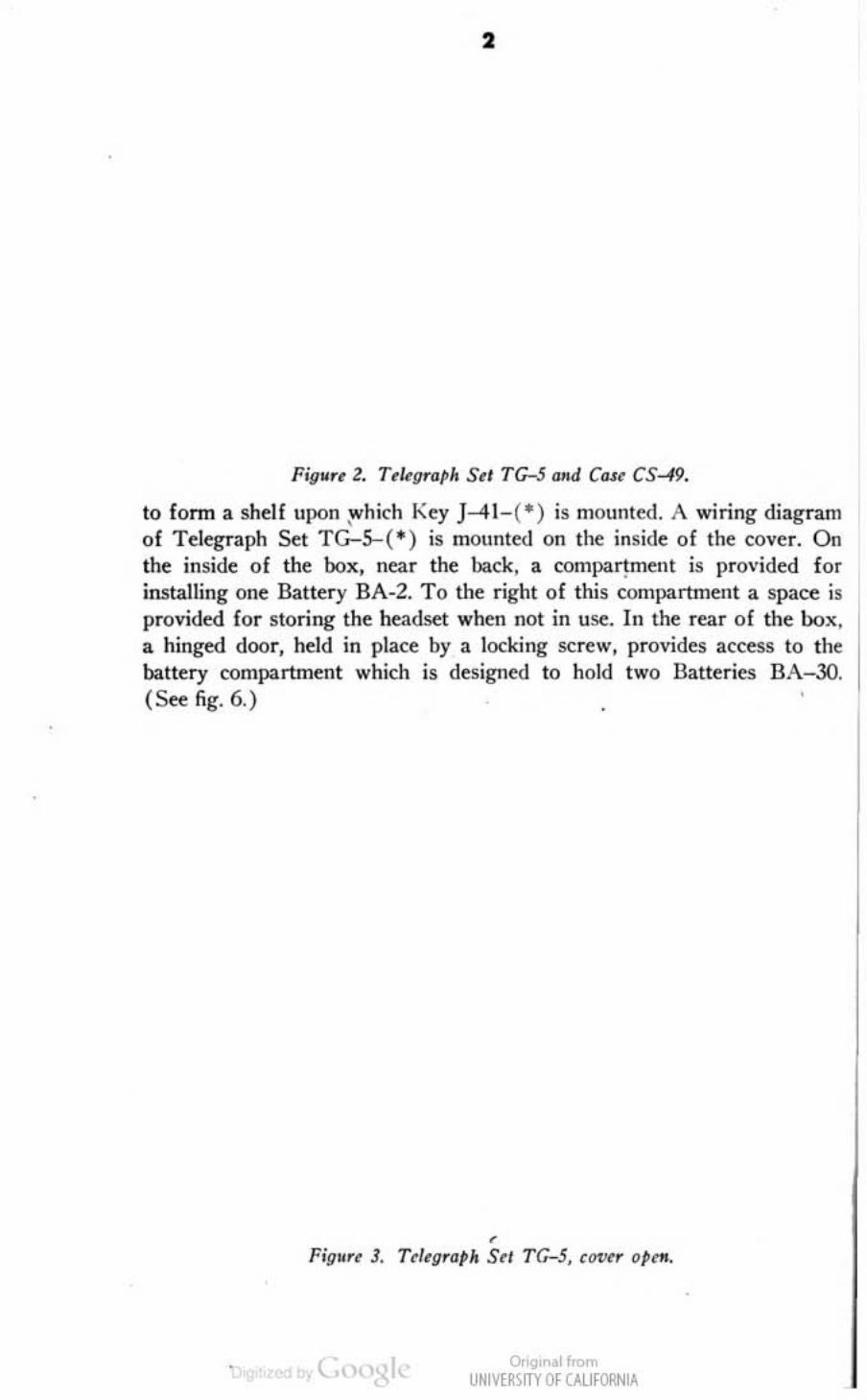
Figwu l. Trllgrnplt S.l TG-5 and ClUe CS-49.
to form a shelf upon :ovhich Key }--41- (*) is mounted. t\ wiring diagram of Telegraph Set TG-5--(*) is mounted on Ihe inside of the cover. On the inside of the box, near the back, a compartment is provided for installing one Battery 8A-2. To the right of this (ompartment a space is provided for storing the headset when not in use. In the rear of tht box. a hinged door, held in place by a locking sc~w, provides access to the battery compartment which is designed to hold two Batteries 8A-30. (~ fig. 6.)
, Figwu 3. T~I.gratJo SrI T G- 5, CQl",r O,tfI,
OOgtr •• 1 If"", UNIVE~\lTY Of CAlifORN IA

•
___ wo,'''' ~ DlAGR.&M
BUIiNISliEII
RECEIVER COMI'IfU!TMENT
-.",." ,.,
Fi!Jure 5. TcI~{)rath Stt TG-5-B, CMIC'I' o~.
0.'9' .11<om UNIVE~SITY Of CALIfORNIA
,
•

•
FigMre 6. Tdrg.aph Stl TG-5-B, .tar u"nu.
C. TEll.M1N AL B LOCK. (I) The terminal block on T~legraph Set TG-S is fastened to the front of the battery compartment with two 5C~WS. It consists of a pie.:e of bakelite 4 inches long, 7/ 16 inches wide, and 5/ 16 inches thick. Five BimJing Posts TM-1SO an: mounted on the terminal block and are labf;led from ld t to right - 3 V, +. ?2V - . L1, and 1.2. (See fig. 3.)
(2) The tenninal block on Telegraph Sets TG-5-A and TG-5-B consists of a molded phenolic block 21i inches long, I H inches wide, and ~ inches thick. Two Binding Posts TM-17S are mounted on the upper right hand ]X)rtion of the block and are labeled Ll and 1.2. Three Binding Posts T M- lSO are mounted on the lower portion of the block and are labeled, f rom right to left -3, +, and -22. (See figs . 4 and 5.)
d, REI.AY BK- 7-C· ). (I) Rtloy BK-l. Relay BK-7 is used in Telegraph Set TG-5 only. The relay is contained in a black bakelite housing and is mounted on the left side of the box just helow the hattery compartment. The front of the relay contains two levers for the adjustment of the relay spring tension and the amlature air gap. The lever on the left is labeled SPR ING and the one on the right GAP. Both levers move over a scale graduated from 0 to 30. (Sc<: fig. 3.)
(2) Relay BK-7-A. Relay BK- 7-A is part of Telegraph Set TG-S-A only. The relay is mounted on a bracket directly in front of the battery compartment and is similar in appearance to RELAY BK_7. Two levers mounted on the f ront of the relay are labeled SPR ING and GAP and move over a scale graduated from 0 to 20. An opening. in the top of the relay case, provides aCttss to the relay contacts for cleaning purposes. (See fig. 4.)
Or;gtr •• 1 If"", <JNIVE~\lTY Of CAlifORN IA

s (3) Relay BK-7-B. Relay BK-7-B is part of Telegraph &t TG-5-B
only. The relay is mounted on a bracket in front of the battery compartment and is similar in appearance to Relays BK-7 and BK-7-A. One lever, mounted on the f ront of the relay ca~, is labeled ADJ UST and moves over a scale graduated from 0 to 40. The armature remains in a fixed position in this relay and the lever adjusts only the spring tension on the movable contact. An opening, in the top of the relay case, provides acress to the relay contacts. This opening is provided with a small clip-on metal cover. (See fig. 5.)
t. BELL (figs. 3, 4, and 5). The bell used in T elegraph Set TG-5-(.) is a d-<: vibrator type and is fitted with a 1 y.j -inch g<lng. A small screw on the side of the belilrame provides a means of adjusting the distance between the fixed contact and the movable contact mounted on ' the dapper arm. In Telegraph Set TG-5 the bell is mounted between the receiver compartment and the right side of the case. In Telegraph Sets TG-5-A and T G-S---B the bell is mounted directly undu the relay.
f. I NTERR UPTER BZ-5 (fig. J). Interrupter BZ-5 is part of Telegraph Set TG-5 only. The interrupter ( howler ) sen'cs as a local tone source for the operator and consists of a double carbon button mounted against the diaphragm of a telephone receiver. Wht'n operating, the interrupter produces a study tone of approximat~ly 1,0Cl0 cydes per second. The interruptt'r is mounted in from of the receiver compartment by means of two scrt'ws through the bottom of the box.
g. INTE\IIlUI'TER BZ-5-G. Interrupter DZ_5-G consists of two single carbon buttons mounted side by side against a common transmitter diaphragm and this combination mounted directly over two rec~i ver diaphragms. \Vhen operating, the int~rrupter produces a continuous tone of approximately 1,0Cl0 cydes.
h. I NTERR UMERS BZ- 7-A, BZ- 7-C, AND BZ-7-J (fig. 4). Interrupter BZ-7-A, BZ-7-C, or BZ-7-J is part of T elegraph Set TG-5-A only and is mounted};ly means of two screws through the bottom of the box, immediately in front of the receiver compartment. It consists of a single carbon button mounted against a receiver diaphragm. When operating, the interrupter produces a continuous tone of approximately t ,OClO cydes per second.
Nal~. Inurrupt.r BZ-S and Interrupt~rs BZ-7_A, BZ-7--C, and BZ-7-J will oll"rale only in the ~ertical po. ition.
i , INTERItlIMER BZ- 7-N (fig. 5) . InternlptC'r nZ-7-N is part of Telegraph Set T G-5-B and is mounted in front of and below the ret:eiver compartment. This interrupter is electrically similar to Interrupter BZ-7-A but much smal1cr in size, and is designed to operate when held in any position,
; . JACK JK-35 ( fi gs. J, 4, and 5). Jack ]K-35 is a tip-sleeve type jack with an extra set of contacts, equivalent to a single-pole, doublt'-throw
Onq, 01",,", UNIVtl1'im OfUUfORNlA

6
switch, operated by the tip spring. The i:lck is mounted in the lower righthand (orner of the box.
k. KEY J-41-(*) (figs. J, 4, and 5). Key J-41-(·) is an open-circuit telegraph type key mounted on a molded phenol ic base which. in turn , is mounted on the folding front portion of the box. The key contains two sets of contacts , one set toward the front of the key lever and the other at the back. In Ihe norma! posi tion, the front contacts a~ open and the back contacts are closed. Three binding posts, two on the right and one on the left, are provided for connecting the key into the circuit. A knurled screw and locknut at the rear of the key lever provides a means of ad justing the opening between the frollt contacts. Another knurled screw and locknut toward the front of the lever is used to adjust the tension of the spring which keeps the front contacts open. The key lever is mounted on the frame by means of two knurled screws threaded through the sides of the frame.
I. H UDsET H S-20 ( figs. 3, 4 , and 5). H eadset H S-20 consists of Receiver R-3, Cord CC-335, and Plug PL-55.
(1) T he ~iver is the magnetic type having a d-c resistance of approximately 80 ohms. The ret:dver is contained in a watch type case having an adjustable web headband fastened to brackets on the sides of the case .
• (2) The cord consists of approximately 4 feet of two-conductor, twisted,
rubber· and braid-covered cord teoninating in Plug PL-55.
3. Packing for Export
Telegraph Set T G-5- ( * ) is p3cked for export in the following manner :
o. One dustproof bag containing 4 ounces of silica gel is placed in the large battery compartmell t, and tw<) du~tproof bags each containing 1 ounce of sil ica gel are placed in the rear battery comparunent .
b. The telegraph set is placed in its carrying case and the cover snapped shut.
c. The telegraph set is then placed in a fiberboard container with the front of the set up. The st rap is neatly folded on the fron l of the case. One pound of sil ica gel in a duslproof bag is placed beside the folded strap.
d. The fiberboard container is then closed, sealed, ami wrapped in a moistureproof and vaporproof paper. (~fig. 7.)
t . This conta iner ancl wrapping is then placed in a fiberboard box and sealed with gummed lape.
I- If more than one telegraph set is to he shipped a t one time. six sets are placed in a nailed wooden crate approximately 23 inches wide, 23 inch es dcep, and 23 inches long. (See fig. 8.)
Onq, ol",,", UNIVtl1'im OfUUfORN lA

7
•
..... III.JCIo _ \
'"It c:t-04t.-tii', "!'.. ' .......... ,
~
Pifll'rr 7. T , I'grpf''' Sri TG-S-B. Ptultrd 1M txltwl,
4. Diff.,.nces in Models of Telegraph Set TG-5--(*)
The differences in models of components of Telegraph Set TG-S-(·) are described in paragraph 2. Operation is the: same for all models with the eXcqltion of the adjustment of Relay BK- 7-( · ). This adjustment is covered in section V. Telegraph Sct TG-S weighs approximately 6 pound! and T elegraph Sets TG-5-A and TG-5-B weigh approximately 7 pounds, including batteries.
OOgtr •• 1 If"", UNIVE~\lTY Of CAlifORNIA
-
. .. .
• Section II. APPLICATION
5. General
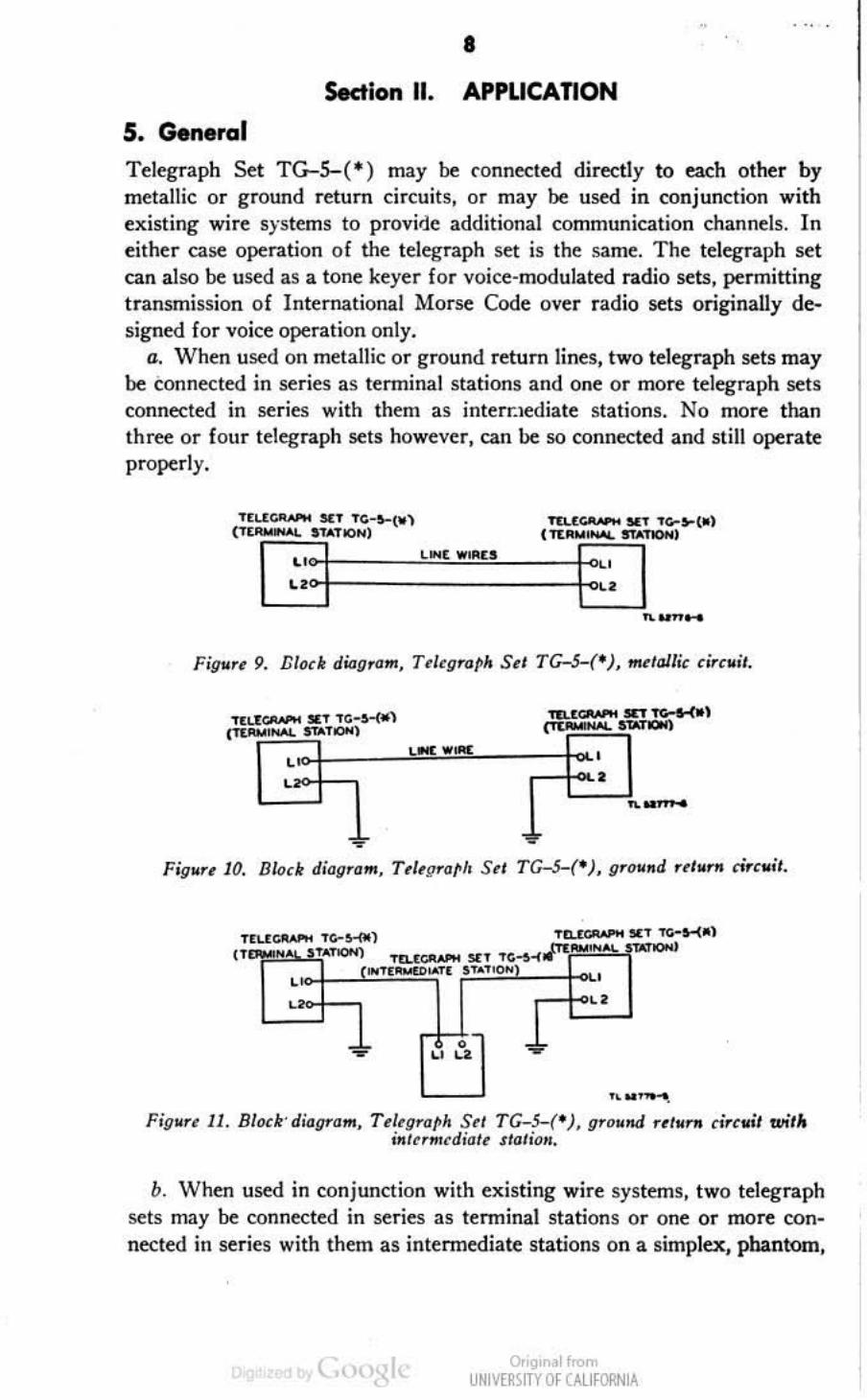
Telegraph Set TG-5-C·) may be connected dire;tly to each other by metallic or ground return circuits, or may be used in conjunction with existing wire systems to provide additional communication channels. In either case operation of the telegraph set is the same. The telegraph set can also be used as a tone keyer for voice-modulated radio sets, permitting transmission of International Morse Code over radio sets originally designed for voice operation only.
G. "When used on metallic or ground return lines, two telegraph sets may be conne<:ted in series as tenninal stations and one or mo~ telegraph sets connected in series with them as interr.lediate stations. No more than three or four telegraph sets however, can be so connected and still operate properly.
" t,
.... '--. FigMr~ 11. BI"dr-d,·"gt'''m, T~I,gT",h S" TG-5-(· ), gr"M..a rt'Mr .. rirc .. it wi'"
iNr" ... ~di,," s,,,,im •.
b. When used in conjunction with existing wire systems, two telegraph sets may be connected in series as terminal stations or one or mo~ oonnected in series with them as intennediate stations on a simplex. phantom,
0.'9' ~I""'" UNIV[RlfTY Of CALIfORNIA

9
or simplex-phantom circuit by use of repeating ooils contained in the equipment with which they are operated.
~ _ w ~
...... , 7
nu_ .. • .......... , c .... _" '-1
... ....... 1
•
Fil1"r~ 13. BIQ~' dw.gr .. ffI , . T~'tIl'''~ S~I rG-~('), &implu ci.",,;, ' '''"'''tdifJl~ s/"/,, . ...
wi,/O
LINE W IRES
1l:1,.(Gf'tAPH $tT TC~~-<*)
2 ( TER .. ,NAL STATION)
CTEL:~t4[ ., SWITCI<8OAAD
nu',,-, Fil1" re U. BI<><1t didg.""" T tltg.",,~ Se' TG-S-(- ), "h""'"m &;.(,,;1.
t . Telegraph Set TG-5---( I ) will operate satisfactorily as a tone keyer with any Signal Corps radio using a standard carbon button microphone, such as Radio Sets SCR-300, SCR-508, SCR-51O, SCR-608, SCR--6lO, and SCR-619. An adapter cord is necessary to permit the use of the telegraph set as a tone keyer. This cord consists of a two-conductor cord terminaling in Plug Pl.-55 on one end and Plug PL-68 on the other. The cord is so wired that the tip and sleeve of Plug P~ are connected together and through the cord to the sleeve of Plug PL-55. The ring of Plug p~
0.'9' ~11n>m UNIV[RlfTY Of CALIfORNIA

10
'-, ... w,oorl
c~ • • CI C~I
n. .. ,.._.
is connected through the cord to the tip of Plug PL-55 in series wi th a 4OO-ohm, }S-watt resistor. The resistor is conn~ted in the circuit to prevent r-£ feedback which results in steady lone modulation in some cases.
Fig,.", 16.
• """" ............ ,"<0 ... _ TO " "·"rr ...
" ....... Bl<ulr ditJrJO'Ilm, T~I'r;~GP" Sel TCc-5-(- ), Ms~d III g ,"", /uy,. 0" (!,,.u_
...odJdq,ttd .ad;o Itl,
6- Rang. The range of Telegraph Sct TG--5-( · ) is dependent on the type. construction, and condition of the wiTe lines used. weather conditions. adjustment of the relay, condition of the battery in the set, and the type of telegraph sets working together. \Vhcn the conditions given above are at their best, the following ranges can be expeded on a simplex circuit:
a. Two Telegraph Sets TG-5-A working togdhcr will operate satisfactorily, al a speed of 20 words per minute ( wpm ), ove:r 50 mile:s of wet Wire: W- lIO-B. On dry WiTe: W- IlO--B the sets will operate: satisfactorily when the total resistantt of the line dCle!l not exceed 23,000 ohms.
b. T wo Telegraph Sets 'TG-S-B working together will operate satisfactorily at a speed of 15 wpm. over 50 miles o f wet W iTe W- 11O--B. On dry Wite W- 110--B the sets will operate satisfactori ly when the total
, resistance of the: line does not e:xceed 72,000 ohms.
(. Telegraph Set TG-S-A working with Telegraph Set TG--5-B will opc:rate: satisfactorily, at a speed of 20 wpm, over 30 miles of wet Wire W-11O-B. Over dry WiTe: W- I1 O--B the sets will operate: satisfactorily when the: resistance: of the: line: dCle!l not c:xceed 26,000 ohms.
0.'9' ~11n>m UNIV[RlfTY Of CALIfORNIA

" Sedion III. INSTALLATION AND ASSEMBLY
7. Uncrating, Unpacking, and Checking
T~legraph Sets TG-5-(*) are packed in a nailed wooden box as shown in figure 8. Each wooden box contains six telegraph !lets which are individually packed in fiblorboard packing boxes. (Sec fig. 7.) T o unpack the telegraph sets follow the pr~du~ 'outlined below.
a. Place the wooden box in a convenient place for opening.
b, Cut and remove the steel straps.
C, Remove the nails from the top and sides of tne box with a nail puller, and remove the top. Do not pry off the top of the box as this may cause damage to the equipment.
d. Remove the individually packaged telegraph sets from the wooden box.
t. Open the top of each fiberboard container and remove the inner fiberboard CQPtainer and moistureproof wrapping.
f. Remove the moistureproof wrapping from the inner fibcdJoord con-lain~r.
g. Open Ih~ lOp of Ih~ inn~r container.
h. Withdraw Ih~ t~l~graph set from th~ inn~r contain~r.
i Open th~ case and r~mov~ the t~l~graph set.
j. Open th~ tel~graph set and remov~ th~ silica gel from th~ batl~ ry compartm~nt.
k. Open the rear battery oompnrtment and remov~ th~ silica g~l.
I. Carefully inspect the equipment for possible damage during shipment.
8. I.ocoting
'.ocat~ Tel~graph Set TG- 5-( . ) where it will not be subj ect to adv~rse weather conditions. Place the telegraph s~1 in an upright position in a manner providing conv~nient access to the key. A wooden frame is desirable for holdin~ the telegraph set in position if it is to be installed semipermanently on a table or other flat surface.
9. Installation of Batteries 0. INST ALLING BATTEIIY BA-2. ( I ) Open the cover of the set.
{2) Place one Battery 8A-2 in the battery compartment.
(3) Connect the positive lead (red wire) to + terminal on the terminal block.
( 4) Connect the negative lead (black wire) to the -22 terminal on
Onq, ol",,", UNIVtl1'im Of U.lJfORNlA

12
the terminal block on Telegraph Set TG-S- A or TG-5-B, or to th .. terminal marked 22V - on Telegraph Set TG-S.
b, I NSTALLING BAITE~ I&s BA-30 (fig. 17 ) . ( 1) O pen the batter~'
compartment in the rear of the telegraph set. (2) Place one Battery BA-.30 in the battery compartment so t hat th ..
bottom ( nega tive contact ) is against the spring mounted on the r ight side of the compartment.
(3) Place a second Battery BA-30 in the compartment so tha t th .. bottom pre5ses against the positive contact of the first batte ry install ed and the po~itive contact presses against the flat metal spring on the left side of the compartment.
Figvrt 11. Ballenn BA- 3D ;1IS/IJllnl ill T rhgT(1rh S,t TG-S-B.
c. EXTER NAL BATTEMY. ( 1) If Batteries BA-30 are not available, any 3-voll d-c source of power may be used by connecting the positivt lead to the terminals on the terminal block marked + and the negative lead to the tenninal marked -3. Remove any batteries installed in the rear battery compartment before connecting an external battery and be sure that the voltage of the external SQurce does not exceed 3 volts.
(2) If Battery BA-2 is not available, any 22~-volt d-c SQurce of power may be used by connecting the positive lead to the tenninal marked + on the tenninal block and the negative lead to the temlinal marked -22 on the terminal block of Telegraph Set TG-5-A or TG-5-B or 10 the terminal marked 22V- on Telegraph Set TG-S. Remove any Battery 8A-2 from the telegraph sct before connecting an external SQurce of power and be sure the voltage of the external source does not exettd 22M volts.
OOgtr •• 1 If"", UNIVE~\lTY Of CAlifORN IA

13
10. Connection of Incoming Lines (fig. 18)
a. Remove Telegraph Set TG-5-( *) from Case C5-49-( - ). b. Open the cover.
c. Starting apI)TOximateiy 4 inches from the ends of the wires to which the telegraph set is 10 be connected, strip off about 2 inches of insulat ion. Scrape and clean the bared metal of the wires.
d. I f the telegraph set is Leing conne..:ted to a metallic cifeui l, eomlee! one wire of the: line to the tenninal marked L1 on the terminal block of the telegraph set. COllll<'£1 the other line wi re to the terminal marked L2. (See fig. 18.)
fl. If the telegraph set is being conne<:ted to a ground return circuit, connect the line wire 10 either line terminal LI or L2. Connect the remaining line terminal to a good ground. (See T1\1 11-755. )
11. Connection of ' : Iegraph Set TG-S--{*) for Use as a Tone Keyer
a. Conne<:t a shorting wire aCTOSS line tenninals L1 and 1..2 of Telegraph Set TG-5--( ·).
b. Insert Plug Pl..-55 of the adapter cord into the headset jack 011 the telegraph set.
c. I nsert Plug PL-68 in to the microphone jack 01 the transmitter.
• OOgtr •• 1 If"", UNIVE~\lTY Of CAlifORN IA

Fig"" 19.
""-0'
•• or ... , ... ,M_OOC
I.
~ .. -..
C"""'CTI(IN' ....... ,.
W irirog of PI~9 PL-.s.s and Plug p~ for "Ie OS Qd<J,,'~r ford <nih Te~fl rapll Sel TG-S-(-),
Fig" •• ZO. Trlegm~" S . t TG-5-B paci: rd for Ir(}1lS,OrlO /WK or IIvrag"
12. Repacking for Transportation and Storage (fig. 20)
a. Remov~ the line wires from the lennina! block. b. Oose and fasten the front and cover of the telegraph set. c. Place the lelegra1)h set in Case CS-49-(.), F asten the CQver.
NDir. If Tdcgraph Set TG-5-(- ) i , to be tranlporlrd or .t~ for" I"'Tiod Jonge' I~n Z !by., remove the Ntler;u from the IIet . •
OOgtr •• 1 If"", UNIVE~\lTY Of CAlifORN IA
15
S.ttion IV· INITIAL ADJUSTMENTS
13. Preliminary Teltl
o. WLLlNG CiRCUIT. Install the batteries in the set. Short circuit the line terminals Ll and 12 while alternately operating the key. The bell s hould be heard when the key is depressed and not when the key is released.
b. TRANSM I TTING j\.Nn RECEIVING CIRCUIT, Insert the headset plug
in the: jack. The inttrrupter should operate and produce a faint tone. S hort the line terminals and operate the key while holding the ~iver to the ear A loud tone should be heard in the receiver when the key is depressed but not when released.
14. Preliminary Adjustments
o. KEY J-41-(* ) . (I) Loosen the locknuts on the four adjusting screws.
(2) Operate the key slowly and adjust the screws on cither side of the frame until the key lever moves freely without sidewise molion. T ighten the locknuts on t~se two screws.
(3) Tum the adjusting screw on the rear of the key lever until the hack contact closes when the key is unoperated and opens when it is operated and th\: desired clearance is obtained between the front contacts. Tighten the locknut.
(4) Adjust the screw on the front of the key lever until the desired spring tension is o.btained. Tighten the locknut.
h. ADJUSTMENT OF BELl .. Shorl terminals L l and I.2 with a screw driver or short piece of wire and depress the key. If the bell does 110t ring procl'<'d as follows:
(1) Insert a screw driver in the slot o f the adjusting screw which protrudes through the top of the bell frame.
(2) Turn the screw clockwise as far as it will go.
(3) Hold down the kcy levcr.
(4) Tum the screw counterclockwise until the bell begins to ring.
c. RELAY BK-7- (·). Adjustment of Relay BK-7-( ·) is covered in section V.
0.'9' ~11n>m UNIV[RlfTY Of CALIfORNIA

,. PART TWO
OPERATING INSTRUCTIONS Nou. For in5truct ioll5 to prev...,! II"" of ~uipm""l by t~ enemy, Sf<! the destructiQII
notice in 1M front of this n""mal.
Section V. PROCEDURE FOR OPERAnON
15. Adjustment of Relay BK-7-(*) a. GENERAL. The n:sistance of the relay in Telegraph Set TG-5-C·)
is a fi:.;cd value and it is necessary, therefore. to adjust the armature so that it will make and break its contacts properly with various values of CUTrent flowing through the relay winding. The resistance of the external circuit connected to terminals L l and L2 determines the value of this current. Consequently the relay must always be adjusted for the circuit o~r which the set is to operate and may need to be adjusted frequently as the resistance of that circuit changes or as stations are added to or felt1(}ved from that circuit. With nonnal line battery installed in the telegraph set, there is a limit to the possible adjustment and if that limit is reached without obtaining satisfactory operation, it may be necessary to increase the voltage on the line as described in paragraph 16.
b. R ELAYS BK-7 AND BK-7-A. When the pointers on Relays BK-7 and BK-7-A are set at 0, the armature spring tension is least and the air gap smallest. At this setting, a current of approximately 1.0 to 1.5 milliamperes is required to operate the relay. If, however, a stronger current Hows through the relay winding, the spring tension will not be: strong enough to break the contacts quickly after the CUITent ceases to How and clear signals will not be obtained. The correct adjustment of the relay consists of properly balancing the pull of the spring on the armature against the puH of the magnetic force developed when current Hows through the relay. The best adjustment for any condition is that which gives satisfactory operations with the smallest values o f GAP and SPRING pointer settings. Therefore, for all adjustments , obtain the smallest GAP pointer setting which will allow the relay to operate and the smallest spring pointer setting that will open the contacts sharply. To 3djust the relay with the telegraph set connected to a line, follow the procedure outlined below.
( I) Place the headset plug across the line terminals with the tip of the plug touching one terminal and the sleeve the other, to determine if another station is using the line. If a station is transmitting, clicks will be heard in the receiver.
0.'9' ~11n>m UNIV[RlfTY Of CALIfORNIA

17
(2) If the line is fr~, place the plug in the jack. ( 3) ~t the SPR I NG and GAP pointers to indicate O. (4) Press t~ key, hold the receiver to the ear, and slowly move the
GAP pointer until tone is heard in the receiver. (5) Release the key. If the tone does not stop. increase the SPRING
pointer setting until the tone stops. (6) If the tone still dots not stop when the SPRING pointer is moved
to its highest setting. increase the GAP setting sl ightly, retum the SPRI NG pointer to zero, and again increase the SPRING pointer setting until the tone stops,
(7) Call the most distant stalion on the line and request it to transmit for testing.
(8) If the distant station's transmission fail s to actuate the relay, proceed as described in paragraph 16.
(9) Call any other stations On the line, and, if necessary, make further adjustments of the relay.
c. RELAY BK~7~B . No adjustment of the annature gap is provided on Relay BK~7~B. \Vhen the ADJ UST pointer is set at 0, the armature spring tension is at a minimum and approximately 0.2 milliamperes as required to operate the relay. If, however, a stronger current flows , th rough the relay winding, the spring tension will not be strong enough t o break the con:acts quickly after the current cea!>eS to {low and dear s ignals will not be obtained. The best possible adjustment is one which will give satisfactory operation with the smallest ADJUST pointer set· ting. To adjust the relay with the telegraph !>ets CQnnecled 10 the line follow the procedure outlined below.
(1) Tesl for a dear line as described in bel) and (2) above. (2) Set the ADJUST pointer 10 0 on the dial. (3) Depress the key and hold the receiver to the ear; tone should be
heard in the receiver. (4) Increa!>e the ADJUST pointer setting until the tone stops. (5) Alternately press and release the key while holding the receiver
t o the ear to detennine if the sii:f\als stop sharply when the key is released. (6) If the signals do not stop sharply when the key is released, increase
the ADJ UST pointer !>etling until they do. (7) Proceed as described in b(7), (8), and (9) above.
16. Additional Line BaHery
If, by placing the tip and sl~ve of the head!>et plug across the line ter· minals L1 and L2, it is detennined that a distant station is transmitting and the relay cannot be adjusted as described in paragraph 15 to give satisfactory operation, proc~d in the following manner:
(I. Add another Battery BA-2 in series with the one already in the set.
0.'9' ~11n>m UNIV[RlfTY Of CALIfORNIA

11
b. Call the distant station and in(onn it that the line baltery has been increased to 45 volts. Request t~ distant station to increase its line battery to the same value and to transmit for funher. test.
/;. Adjust I~ relay as described in paragraph 15. d. If sat isfactory operation still cannot be obtained, add a third Bat
tery BA-2 in series with the other two and res~at the procedure given in band (' above.
emilio",: It i ~ possible to cause serious damage \0 the sd by .adding an c}<cessive amount of line battery. If the keys of two or more sets are depressed simultaneously, the combined voltage of all the batteries in the sets will be impressed upon the series circuit containing all the relays. Add only enough voltage to assure satisfactory operation, and no more.
17. Operation
o. TIlANS1IITT1NG. Operate the key in accordance with instructions given in TM 11-459.
b. Rl':cI':IVll'IG. During reception. use may be made o f either the bell or interrupter contained in the telegraph set. If use of the bell is desired, remove the headset plug from the jack.
c. BRF ... \ K-IN. If during re«ption it is desired to break in on the transmission, slowly depress and release the key. This action will cause faulty operation of the relay at the transmitting station and will indieate to the operator that a break-in is desired.
d. CoNTISUOUS OPEIUo.TION. If the set is to be operated continuOU5ly, keep the headset plugged into the telegraph set. Call signals are then received only in the headset, which must be worn to prevent mi ssing a call.
t. STAN()oBY OI'ERATiON. Remove the headset plug from the jack. Call signals will then be indicated by the ringing of the bell.
Section VI. EQUIPMENT PERFORMANCE CHECK SHEET
18. Purpose and Use of Equipment Performance Chttck Sheet
Q. G ENUAl.. The equipment pcrforman~ check sheet (par. 19) will help the operator to determine whether Telegraph Set TG-S-(.,. is functioning properly. The cbeck sheet gives the item to be checked, the conditions under which the item is checked, the normal indications, and the corrective measures that the operator can take. I tems I, 2, and 3 arc performed when preparing the equipment fo r use, items 4, 5, and 6 are checked when starting, items 7 and 8 during operation, and items 9 and 10 when stopping operation. Items 7 and 8 should be checked at least Onte during a normal operating period or at least four times each day during continuous operation.
OOgtr •• 1 If-om UNIVE~\lTY Of CAlifORN IA
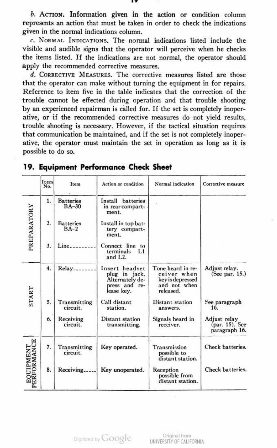
b. ACTION. Information given in the action or condition column represents an action that must be taken in order 10 check the indications given in the nonnal indications column.
c. NORM .... l. INDICA TIO NS. The nonnal indications listed include the visible and audible signs that the operator will perceive when he checks the items listed. If the indications 3re not normal, the operator should apply the recommended corrective measures.
rIo CORRF.CTIVE MEA SUR ES. The corrcrtive measu~s listed are those that the operator can make without turning the equipment in for repairs. R eference to item fi ve in the table indicates that the correction of the trouble cannot be effected during (Jperation and that trouble shooting by an experienced ~painnan is called for. If the 5et is completely inoperative, or if the recommended corrective measures do not yield results, t rouble shooting is necessary. However, if the tactical situ3tion requires t h3t communication be m3int3ined, 3nd if the set is not completely inoperative, the opc:r3tor must m3intain the set in operation as long as it is possible to do 50.
19. Equipment P.rformance Check Sheet -It~ .. It . .. "- . -
•• Batterie& > BA- 30 • 0 e-< ,. i4ueries • BA- 2 < " W • ,. Linc. _ • •• _ •..
" -
•• Relay •• .•••• •
e-• ~ ,. T ranom,tling " ci",u;t.
,. R"",i"i.ng CI",ml.
-W
e-u ,. Tra.no,,!illing ZZ CIrcUli. w< . , ". -0 o . §rei
8. Recei ving •••••
"
Action"" c<>odhlon
[nota ll batteries in rear com parl- , ment.
Inota ll in lo p ba "
"" coni part· men l.
Con nco;, lin~ ,,, ,erminal. U and L2.
In.en had~~ t plug '" jack. Altemate:?, de· r:: an "". "" .. key.
Call dis tant . tation.
Di. tanl . talion Iran. mining.
Key operated.
Key uoopen.ted .
N""",a l 'ndleaU"n C""' .... ,'" "' .... n ..
T one h~n:I in ..,... ed"'" "'he n ke y i. depre" Fd and not " 'hen ""Icaoed.
Distan l ",a ti"" an. weTS.
S;gnal ~ h~an:l ;n rec.,,'"er,
TraosOli .. ion poosible 10 di . tant station .
Reception ponib le from di. tan t Slation .
0.'9' ~11n>m UNIV[RlfTY Of CALIfORNIA
Adjust ",lay. (s.., par. 15.)
~et rragrnph • •
Mju. , ..,lay (par. 15). s.., paragraph 16.
Check bailer;....
Check batteri"".

I .. ", ,,-,. -• ,. Balteriet __ _ ._ 0 ~ 10. Line . ___ ..•• •
. •
20
A«I.,., "" .....dill<x> """"'.llndl<o ..... Co"..!<tl.< "' .... '"
Remove batlerie5.
Dioconnect line.
•
--•
• •
Onq, ol",,", UNIVtl1'im OfUUfORN lA

21
PART THREE
PREVENTIVE MAINTENANCE
Section VII. PREVENTIVE MAINTENANCE TECHNIQUES
20. Meaning of Preventive Maintenance
Preventive maintenance is a systematic series of operations perrOI Il)ed at regular intervals on equipment to f'liminate major break-downs and unwanted interruptions in service. and to keep the equipment operating at top efficiency. To understand what is meant by preventive maintenance, it is necessary to distinguish betw~n preventive maintenance, trouble shoot ing, and repair. The primary fnnction of preventive maintenance is the prevention of break.downs and, therefore, the oeed for repair . The primary function of trouble shooting and repair is the location and correction of existing defect s. The importance of preventive main tenance cannot be ovt'remphasized. T he ent ire system of wi re communication depends upon each set king i,l opero/ion when it is nee<led and also ullOn its opero/ing efficiency.
N ol r. The optratia ... i" ..",I;on V II a re """.id .... <1 fi rst· all,j """""d· ...,hdon (organi~ Ealion o!,<,ra lOrJ and r .. pairmm) maintenance.
21 · Description of Preventive Maintenonce Techniques o. GENf,RAL. Most of the parts used in Telegraph Set TG-5-( · ) require
r outine preventive maintenance. Those requiring maintenance differ in the amount and ki~d re"uired. BKause hit-or-miss maintenance tKhniques cannot be applied. defmite and speci fic instructions are needed. T his section of the manual contains these specific instntctions and serves as a guide for ~rsonnel assigned to perform the six basic maintenance operations: Feel. Inspect, Tighten. Oean, Adjust, and Lubricate. Throughout this manual the follow ing lettering system will be used for the s ix operations :
F-Feel· I- Inspect
T- Tighten C--Clean A-Adjust L-Lubricate·
The fi tst two operations establ ish the need for the other four. The SeiKt ion o f operations is based on the general knowledge of field needs. For
• n.. 10,1 and I ~br",," "",rat;""', .'" _ .pplkabk '" If.l., ...... Set TG-~( · ).
Onq, ollron> UNIVtl1'im OfUUfORNlA

22
c~mple. dust encountered on dirt roads during cross-country travel filters into the equipment no matter how much care is taken to prevent it . Rapid changes in weather (such as heavy rain followed by blistering heat). excessive dampness, snow, and icc lend to cause corrosion o f exposed surfaces and parts. \Vithou! frequent inspections and the perfonnance of necessary tigh tening, cleaning, and lubricating operations, equipment becomes undependable and subject to break-down.
b. FEEL. The feel operation is used most often to check for overheating.
/;. INSPECT. Inspection is the most important operation in the preventive maintenance program. A careless observer will overlook the evidences of minor trouble. Although these minor defects may not interfere with the performance of the equipment, valuable time and effort can be saved if they are corrected before they ll'ad to major break-downs. Make every effort to berome thoroughly familiar with the indications of normal functioning, in order to he ahle to rl"Cogni7.c the signs of defective equipment. Inspect ion consists of carefully oh!W'~ving all !,art~ of the equipment, noticing their color, placement, state of cleanliness, etc. Inspect for the following condi tions:
(I) Overheating. as indicated by discoloration. hlistering. or bulging of the parIS or ~nrface of the container ; leakage of insulating compounds ; and oxidation of metal contact surfaces.
(2) Placement, by ob!W'rving tha t all leads and cabling arc i:1 their original positions.
(3) Cleanliness, by carefully examining all reces!W's in the units for accumulations of dust, especially betw~n ronnecting terminals. Parts, connections, and joints should be free of dust, corrosion, and other foreign matter. In tropical and high-humidity locations, look for fungus growth and mildew.
(4) Tightness, by testing any connection or mounting which appears to be loo!W'.
d. TIGHTEN", CLEAN "'NO ADJUST. The!W' operations are !W'lf-explanatory. Specific procedures for po:orforming them arc given in paragraphs 23 through 34 whenever necessary.
Caution: Screws, bolts, and nuts should not be tightened careleSllly. Fittings tightened beyond the pressure for which they are designed will be damaged or broken. \Vhenever a loo!W' ronnection is tightened, moistureproof and fungiproof it again by applying the varnish with a small brush. See section X for details of moistureproofing and fungiproofing.
r. L UB RIC",TF.. Lubrication means the addition of oil or grease to form a film between two surfaces that slide against each other, in order to prevent mechanical wear from friction.
Or'9,"~lln>m UNIV[RlfTY Of CALIfORNIA

23
22. Common ,Materials Needed Nole. 'The 1001, and materials listed below mun be at hand !>tlore ltart;,,&, the pre
.'cnt;"" maintenance pTo<edur~ •.
The following is a list of the tools and materials n~ded for performing preventive maintenance operations on Telegraph Set TG-S-C. ) .
Long-no~ pliers. Diagonal pliers. 3~ inch cabinet screw driver. Solvent, Dry Cleaning. Federal spec No. PS-661a. Burnisher Signal Corps stock No. 4A2005A/S. Neat's-foot oil. Bristle brushes, Saddle soap. Cleaning doth~. Crocus doth.
NOI~. Gasoline will not be u~ a. a c1 ... ning flui<1 for any purpo.." Solvent. dryd ... n;ng. i. available a. a cl eaning fluid through e.tabl i,hed supply (hannels. Oil, fuel, dietel. may be used for deaning PUrpose! when dry·deaning solv""t is not on hoo. Drbon tetrachloride will be used as a cleaning fluid only where specified for cleaning contact part. of electrical equipment. or a . s"",ilied where inAam~blc solvents can· not he uocd because: of the lire hazard. Oil, fuel, diesel, will " ", be used for cleaning dectrical contact !..
23. Box, Exte rior
fl. INSPECT ( I ). Inspect the box for damaged places, dirt, dust, rust, corrosion. and loose, damaged. or missing screws.
b. TIGHTEN (T). With a suitable screw driver, lighten all screws snugly.
c. CLEAN (C) . \Vilh a dean, dry doth, wipe al! dirt and dust off the hox. NM~. In onler to pc.fom! the [>,eventive maintena""e operations contained in the
following p.:oragraphs, it will be necen ary 10 open the OOX and rur battery compart· ment.
24. Rear Boffery Compartment
o. I NSPECT (I). Inspect the battery compartment for dirt, dust, corrosion, and loose or missing battery contact springs.
b. CLEAN (C). \Vith a soft bristle brush, remove all dirt, dust, and fo reign matter from the battery compartment. Carefully dean the battery contact springs with crocus dOlh to insure good e1tttrical conntttions.
25. Line Boffery Compartment
fl. INSPECT (I). Inspect the battery compartm,-,nt for dirt, dust, and other foreign matter.
b. CLEAN' (C) . With a soft bristle brush, remove all dirt, dust, and foreign matter.
Onq, ol",,", UNIVtl1'im OfUUfORNlA

2.
26. Terminal Block o. INSPECT (1) . Inspect the terminal block for cracks, chips, or breaks.
Check for loose: and damaged terminals. Inspect the te rminal block and terminals for dirt, dust, and corrosion. Check for loose connel:tions.
b. TIGIlTEN (T). Tighten all loose terminals and loose connections. c. CLEAN (e). Remove: all dirt , dust, and foreign matter on the ter
minal block and terminals, using a soft bristle: brush.
27. Receiver R-3
a. I NSPECT ( I ). Inspect the receiver for dirt. dust, and chipped. cracked, or broken places. Inspect the exterior only. Inspect the headband for tears or frayed edges.
b. eLL\!' (e). Wipe all di rt. dust, and other foreign matter [rom the re~iver with a clean, dry cloth.
28. Cord CC-33S
a. INSI'ECT (n. Inspect the: cord for dirt , dust. oil , grease, and damaged or broken insulation, Examine the cord, where it en ters the rece iver , lor worn or Irayed insulation. .
b. CLEAN (C). Wipe off all dust and din using a dean, dry doth. II it becomes necessary to remove oil or grease, use dry·cleaning solvent.
29. Plug PL-55
a. INSI'F.CT (I). Inspect the plug for hent or broken "parts. Check for an accumulation of dust and din.
b. Cu:"", (C). Wipe off the plug with a dean rag moistened in drydeaning solvent.
30. Case CS 49-(*)
a. INSPECT (I ). Inspect the case for tom or frayed portions. Check for breaks or cracks in the leather corners and bottom. Inspect the snap fastener 10 sec: that it is mourned firmly in the case.
b. CLEAN (C). With a dean, dry cloth wipe all di rt and dust off the case. Use saddle soap and neat's-foot oil to dean the leather portions of the case. Wash the st rap with soap and water.
31. Interrupters BZ-5-{*) and BZ-7-(*} o. I N,rF.CT ( I ). Insp'ect the external portion of the interrupter for
accumulations o f dirt, dust, and other foreign matter. Check for dents , cracks, and breaks in the case. Check for loose connections.
Onq, ol Iron> UNIVtl1'im OfUtJfORNlA

b. TIGIITEN (T ). Tighten all loose connections.
t. CLEAN (C) . Clean the uternal portion of the case with a soft bristle brush.
32. Relays BK-7-A ancl 8K-7-8 u. INSPECT ( I ). Inspect the relay case for accumulation of dirt and
dust. Check to see that there are no chipped or broken parts. Inspect the relay contacts for pitied or worn pla~s . I n~pect thc metal covcr on Relay BK-7-B for bent portions and see that it is in place.
b. CLEAN (C). Oean the e.llterior of the case with a dean, dry doth. Carefully burnish the relay contacts with the burnisher furnished with the telegraph set. Place the burnisher betwccn the contacts and press the contacts together lightly with the tips of the lingers. Move the burnisher back and forth until the contacts are clean and smooth.
t. ADJUST (A). Adjust the contacts as described in paragraph 15 when putting the set back into operation.
Nol,. The (ontacts of Rel ~f BK-7 eannol t.. burnishtd without removing the nlaJ' from 1m, set. This procedure IS coven<! in "'etion XI.
33. Bell
a. I NSPECT ( I) . Inspect the exterior portion of the bell for dirt, dust , nlst, and other foreign matter. Remove the bell cover and check the m ntacts for pitted or worn spots. Check for loose connections.
b. CL!;AN (C). Carefully remove all di rt, dust, and other foreign matter on the bell, using a soft bristle brush. Be careful not to disconnect or damage any of the wiring. Burnish the contacts with a contact burnisher. Pla~ the burnisher between the contacts and move it back and forth until the contacts are smooth and bright.
34- Key ~'-{*) u. I NSPECT (I). Inspect the key for hroken or worn parts. Oleck for
loose connections. Inspect the key for missing parts.
b. TIGUTEN (T ). Tighten all loose screws e.llccpt those used for adjustments. Tighten a1\ loose connections.
r. CLEAN (C) . Qtan all dirty or worn contacts with a contact burnisher. Place the contact burnisher betwccn the contacts. Press the contacts together by e.llert ing a light pressure on the key lever. Move the burnisher back and forth until the contacts are dean and bright.
d. ADJUST (A). Adjust the key, before operation, as described in paragraph 14. '
0.'9' ~11n>m UNIV[RlfTY Of CALIfORNIA

26
Section VIII. PREVENTIve MAINTENANCE CHECK LIST
35. Preventive Maintenance Check List a. For ease and efficiency of performance, preventive maintenance on
Telegraph Sct TG-5- C· ) will be broken down into daily, weekly, and monthly items.
Nelt. The time ;nle ..... al. lot performing tht (I~ventivc ma;nten~""c outlined in the prec~d;ng ~r~graphs and the check lis, _y be reduced at any lime by the local comrmnder. H owe ver, for b<-, j p<rfor mancc of th e "'lUipmml, perform the opo:ration. al lan at fl"«juen!ly a. cant<! for in tht c~k list.
b. The general techniques involved and application of FITCAL operations in pcrfonning prnentive maintenance on individual paris are discussed in section VII. These general instructions arc nol repeated in this section. Personnel performing preventive maintenance will refer to section VII when more dl'tailed information is required on the itl'nJs listed in the following scheduk. After preventive maintenance has been performed on a given day, the equipment will be put into opera tion and checked for satisfactory performance.
Wbe<> por/or .. «l ,,- OtomoUO<l I>a<rip.l"" D.H~ I Woo:kly I M"" ,hly &h<lon
I I, T , C Box, utmor (par. 23) __ . _____ . , , I. C Rear ba ttery compartment ,
3 I. C (par. U).
Line battery compartm~nt , (par. 25) .
• I, T, C Terminal block (par. 26) __ . __ . , 3 I. C Re<:f!iver R~3 (par. 27)_ . _____ . , , I.C Cord CC~335 (par. 28) ______ _ . , , I. C Plug PI..~55 <r.ir. 2<;1 }. __ ••• ___ • , , I. C Case CS-49- oJ ter. 3O)_. ___ . , 9 l. T . C Interruptenl BZ- (0) and
BZ-7- (O) (par. 31 ). 10 I, C, A Rda ys RK-7-A and BK-7-1l
" I. e Be\r~~~h) ___ ____ __ ___ . _. __ " I, T,C,A Key -41-(0) (par. 34)_ . ______
F" I T C !\ Feel Inspect Tigh.en Clean ,\dju",
• The ltd ... <1 t~""I"" .. OI><, •• j ....... no< .ppl j<obl< '0 T<t<lto~b s .. TG-!-(- I.
Section IX. LUBRICATION
Lubrication of this equipment is not required.
, , , ,
I" I"
h'
I" h' I" I" I., I"
" " " " Lubricate
Section X. MOISTUREPROOFING AND FUNGIPROOFING
36. General \ ..,hen o~rated in tropical areas whcre temperature and rela ti ve humidity are extremely high, Signal Corps equipment requires special attention. These are some of the problems met:
Onq, ol",,", UNIVtl1'im OfUUfORN lA

•
27
o. Capacitors, coils, etc., fail because of the effects of fungus growth and excessive moisture.
b. Electrolytic action, oftm visible in the form of corrosion, lak"s place in coils, etc. , causing eventual break-down.
c. Hook-up wire insulation and cable insulation break down. Fungus growth accelerates deterioration.
d. Moisture forms electrical leakage paths on terminal blocks and insulating strips, causing fla sh-ovns and CTosstalk.
c. Moisture provides leakage paths betwn-Il battery terminals.
37. Treatment
A moiSlureproofing amI fungiproofing treatment has been devised which, i f properly applied, provides a reaoonablc degree o f protection against fungus growth, in~ts. corrosion, salt spray, and moisture. The t reatm ent involves t he use of a moisture- and fungi-resistant varnish appli~d with a spray gun or brush. See TB 5 TG 13 for a detailed description o f the varnish-spray method of moistureproofing and fUngiproofing and t he suppli~s and equipm~nt required in this treatment.
Cau'ion: Varnish spray may have poisonous eff«ts if inhaled. To avoid inhaling spray. use respirator if available; otherwi5~, fasten cheesecloth or other doth material over nose and mouth. N~ver spray varnish or lacquer near all open Harne. Do 1I0t smok~ in a I'OOfr. where varnish or lacquer is being spray~d. The spray may be highly explosive.
38. T.legraph Set TG-S-(*)
a. PXI':I'AXATION. Make all repairs and adjustments ,,~cssary for th~ proper operation of th~ equipment.
b. DISASSEMBLY. (I) Raise the cov~r of the telegraph set and open the front panel.
(2) Remove the bel! and discollnect the attached leads. (3) Remove the two screws which hold the jack moullting to the right
side of the case, and pull jack forward. Do not disoonnect th~ wiring. (4) Remove th~ screws from the binding post mounting plate and
expose the back of the plate. Do not disconnect the wiring. (5) Remove Battery BA- 2 from the line battery compartment. (6) Open Ih~ door to the rear battery compartment and remO\'c the
t wo natt~ries nA-30. The batteries are nol to be tr~ated.
c. CLEANING. Oean al! dirt, dust. rust, fuogus, oil, grease, etc., from the equipment to he processed.
d. MASIONG (fig. 21). Cov~r the following parts with maskillg tape:
(1) Te!~graph key.
( 2) Spring and key contacts of jack .
Onq, ol",,", UNIVtl1'im Of UlJfORNlA
-

· 28
(3) Openings in relay cover base, and adjusting ann.
e 4) Binding post wiring slots.
(5) Tenninals o f leads disconneeted from bell.
(6) Battery contacts in rear battery compartment.
e. DRYI!o!G. Place all equipment, I:' xcept the batteries, in an oven or under heat lamps and dry for 2 to 3 hours at 160' F. Do not apply heat to the batteries.
f. VAIlNISH ING. (I) Apply three coats of moistureproofing and fungi. proofing varnish ( Lac(]ucr, Fungus-resistant, spec No. 71-2202 (stock No. 6Gl005.3). or equal. with a spray gun. Allow each ccat to air-dry for IS to 20 minutes before applying the ne,.-! coat.
(2) Apply varnish immediately after the equipment is dried. If varnish is not applied immediately, moisture condenses on the equipment. Varnish applied over the moisture peels off readily after the varnish has dried.
(3) Remove the cover from the bell and varnish the coils, using a brush.
OOgtr •• 1 If"", UNIVE~\lTY Of CAlifORN IA

29
g. REASSEMBLY. (1) Remove all masking tape being careful not to peel varnish from nearby areas.
(2) Reassemble the telegraph set and test its operation.
h. MAIlKING. Mark the letters MFP and the date of treatment near the nameplate on cover.
Exomple: MFP-3 Feb 45.
39. MoistureprooAng and Fungipt'ooflng Aft.r Repairs
If, during repair. the coating of protective varnish has ~n punctured o r broken, and if complete treatment is not needed to reseal the equipment, apply a brush coat to the affected part. Be sure the break is completely sealed.
Onq, ol",,", UNIVtl1'im OfUUfORNlA

,. PART FOUR
AUXILIARY EQUIPMENT
(NOT USED)
, I UNIVEIMY 01' ("'UH"'II~

.. PART FIVE
REPAIR INSTRUCTIONS
No/t. Failure or un5llusiactGl"y performance of equipment used by Army Ground Force, and Army ~vi<:e For~. will be reported on WD AGO Fv rn 468 (Unyti ... factory Equipment Rep<)rt ); by Army Air For~. 00 Army Air f~r"l Form 5-1 (wnatidactory "'lXIrt). If eithn form i. nor ~vail:lLle, preJl'lre the data according to the sample form reprodoced in figure 4\.
Sidton XI. THEORY OF TELEGRAPH SET TG 5 (*)
40. Circuit Elements II. RECEIYf:R. T he rettiver is of the magnetic type. It consists of two
coils, connected in series, wound on the pole pieces of a permanent magnet mounted in a watch type case. The rl:'sistance of the coil windings is approximately 80 ohms. A thin metal diaphragm is placed immediately over the pole pieces of the magnet and is held in place by a screw .cap which serves as an earpiKc and protects the inside of the case from dust and dirt. Cord CC-335 is fastened by screw type tenninals to the ends of the coil inside the case and the opposite end of the cord is terminated in PIng PL.-55.
h. REC£IVER J AC K. The receiver jack consists of two fixed and two movable contacts mounted on a metal frame which, in turn, is mounted on a phenolic block fastened to the box. In the normal position the two bottom contacts are closed and the top contacts open. \Vhen the pIng is inserted in the jack the tip spring is forced np, opening the bottom set of contacts and closing the top sct of contacts.
c. CAPACITOR CA-21O. The capacitor consists of two 0.25 microfarad units inclosed in a metal can. Leads for each section are brought out separately.
d. BELL. The bell contains two coils of wire, connected in series, amI mounted side by side on the bell frame. T he total resistance of the roils is approximately 16 ohms. A soft·iron armatnre is mounted di rectly over the coils. One end of th is annature is pivoted on the bell frame, and the other end is provided with a metal clapper. Two contacts are provided, one mounted on the annature and the other fastened to the bell frame. In the normal posit ion these two contacts are closed. When direct current is applied to the bell terminals, current Aows through these con· bets and through the coils. Current Aowing through the coils produces a magnetic field which attracts the armature and opens the contacts.
Onq, ol",,", UNIVtl1'im OfUUfORNlA
32
\Vhen the contacts open, current ceases to flow through the coil, the armature returns to its nonnal position. and the contacts dost, allowing current to flow, and the cycle repeats. This movement of the armature causes the clapper to strike the gong and a ringing sound results.
e. INTERRUPTER. The interrupter consists of a carbon button transmitter mounted against the diaphragm of a magnetic type noccivc:r and wired in series with it. When direc:t current flows through the receiver ~tion, the ~iver diaphragm is attracted toward the re~iver pole pieces. Since this diaphragm is mounted directly against the transmitter button, the button moves with it and causes an increase in the transmitter resistance .. This increase in resistance causes a reduction in the amount of current flowing through the r~eivet which allows the diaphragm to move outward. \Vhen the diaphragm moves outward it presses against the transmitter button, reduces the resistance of the transmitter, and again allows more current to flow through the t~eiver. This action repeats itself as long as the interrupter is connected in the circuit.
f. RELAY BK-7 AND BK-7-A. Relay BK-7 and BK-7-A consist of a coil of wi~, a movable horseshoe shaped core, two fixed, and one movable contact mounted inside a phenolic casco The coil is wound on a phenolic bobbin and the t"'nds connected to a terminal strip mounted on the end of the relay casco The resistance of the coil in Relay BK-7 is 150 ohms and in Relay BK-7-A, 6CX) ohms. One leg of the core slides inside the coil and the opposite leg passes outside the bottom of the coil. A small rack is screwed to this leg approximately at its center. T his rack meshes with a pinion gear mounted on a shaft passing through the sides of the re lay casco Movement of a pointer fastened to this shaft outside the rday case causes the pinion gear to rotate, which in turn moves the core. The relay contacts arc mounted directly in front of the end of the core. A movable contact is pivoted at its center and the hottom is. fastened to a small spring. The opposite end of this spring iii fastened to a piece of string, which in turn is fastened to a shaft passing through the sides of the relay casc. When the shaft is turned by a pointer fastened to it on the outside of the case, the spring tension on the movable contact is increased or d~reascd accordingly. There· fore, by adjustment of these two levers the gap between the movable contact and the co~, and the spring tension on the contact, can be adjusted. The two fixed contacts are mounted to the relay case hy means of a screw through the contact near the bottom end. The distance between these two contacts and the movable contact can be adjusted by two screws threaded through the end of the relay casc. Thesc two fixed contacts arc connected to the tenninal strip on the end of the ~lay by Hat metal conductors. The movahle contact is connected by a Hexible wire to a solid conductor which terminates at the terminal strip.
g. RELAY BK-7-B. Relay BK-7-B is cons tructed in the same man-
0.'9' ~11n>m UNIV[RlfTY Of CALIfORNIA

33
ner as Rday BK- 7 and BK- 7- A except that the (ore o f t~ rday winding remains in a fixed posi tion and no provisions are made for the adjustment of the air gap betw('{'n the movable contact and the core. The resistance of the rclay winding in Relay BK-7-B is 4,400 ohms.
41. Theory of Operation a. LINE C IRCUIT. ( I) T he L2 hinding post, relay winding, key, and
Ll binding post are connected in series, and form the line circuit . ( 2) Incoming current, flowing through terminal L2, the relay wind
ing, rea r contact of the key, and out through tenninal Lt , operates the relay, thereby dosing a local circuit in the set. ( Sec: figs. 22 and 23.)
,~Ttu" .. tR Il-l-]' ]
.L T IS S •• ..,L , "" . 'uo U.Acoro.
Fig~,~ n. Li~c (iTCII;', Trlcy,~tll s., TG_5,
(3) Outgoing current is furnished by a 220' \,011 battery ( Battery BA-2) which is connected in series with thc front cOlitact of the key and terminal Ll. Depressing the key c1nsc:s the circuit to the battery and allows current to flow through the key lever and front contact of the key, the relay winding, over the line, and back to the battery. (See figs. 24 and 25.)
(4) Sparking betwC('n the contacts of the key. caused by the magnetic fi eld surrounding the relay breaking down through the winding, is suppressed by placing a 0.25 microfarad capacitor in parallel with the contacts. (Sec fig s. 24 and 25.)
b. LocAL CIRCUITS. ( 1) The bell, or signaling circuit, consists of the bell, relay contacts, 3-volt doc supply. and the break contacts of the jack.
Onq, ol",,", UNIVtl1'im OfUUfORNlA

34
lEU, ""_101 IKE " 01 U
"0'1 , U$I$TUG..: g, Inoy lie" ·. 1$ 10011. ~n"""Gl g, UUY '.·T_, 1$ .... 00.11. + .. $Y"""," '011 , .. '" "".C"O~ ..........
Fig"r~ 21. Li~~ circuit, TtI~(Jra~1o S"I TG--5-A aM TG-5-B.
The parts are wired in series, and are controlled by the operation of the ~lay in the line circuit. (See figs. 26 and 27. )
. (2) The interrupter circuit consists of the interrupter, make contact
of the jack, and a 3-w lt doc supply. Insert ing the plug of the headset •
in the jack doses the make contact, opens the bell circuit, and puts the interrupter in operation. (Sec figs. 28 and 29.)
I.TU~u.'U U· ~ ·I.'
.HL ...
0.'91 ~11n>m UNIV[RlfTY Of CALIfORNIA
Mct:IVU ,.,
.........

o.n ....
ru~.. I.T~""""TU N· ' ·~
35
K LL I.A
LI L'
-" -
CORO ,,_""
(.3) T he rtteiving circuit consists of the Receiver R-J, plug, jack, and relay contacts, and a 0.25 microfarad capaci tor connected in series and the combination connected in parallel with the interrupter. \\'hen the relay contacts are closed, the varying voltage across the interrupter is impressed across the receiver causing a tone of approximately 1,QIX) cycles to be heard in it. Shorting of the battery in the in terrupter circuit by the receiver is p revented by the capacitor in series with the receiver .
i T
..
IMT(""""T[. Il· ~ ·l.'
Onq, ol",,", UNIVtl1'im OfUUfORNlA
" .. ",.-

..
1'0'1: _UII .... " 01' "' ..... " · ' - A IS Il0011. USi.'MU (JI III~.' III- r-e _ .. 40011.
.L ., 11'- , .. ill CO"ClfOll ......... .. ' ,- ,
- F;g.~, 21. Sigul"'l1 rimnl, T'''r-~. S,'s TG-J-A""" TG-J.-B.
Section XII. nSf EQUIPMENT
42. General
A voltohmmeter is the only U'S! ~uipment normally required for field maintenance of Telegraph Set TG-5-( · ). Two voltohmmeters which are available in the field are Voltohnuneter 1- 166 and Test &! TS-26/ TSM.
.L T
-.. JljI\'ERSIlY Of (AlIfOlNIA
-,~
'"'
.... -

37
."
OOO'IL , RU'STUU f1' . ....... _._ ~ ~ lIGOn U S,ST.NC( 0# HUT .. -r-e 1$ ... OOA + II 1'_ ' 011 ' ''lO ~'",lToo. ..... , ....
FigwTe 29. J"'nT'wpl" ci,cuil, TekgTol'1I Sets TG-.S-A oM TG-.S-B.
C/mlwn: Before using a voltohmmcter for chttking resistances in Telegraph Set TG-S~( · ) , always remove the batteries from the telegraph sct to prevent damage to the voltohmmcter.
43. Voltohm .... 'et' 1-166 This test set is contained in Test Equipment IE-29. Vohohmmetcr 1- 166 can be used for making continuity. voltage, and res istance measurements.
~ ,UNIV[RlfTY Of CALIfORNIA
"",...-t

3 •
... 1Il0'l1 , ~EI'ITA.U: 0# MU' .. _7_A IS t.OOA
.tllst .... " DO' .! ~., " _7_' IS .... OOA * II ,.-. '011 "'U """""011 " ..... -0
Fig .. ~~ 31. R,uivi"g cirrtlil , Ttltfll'/Il. Srr. TG-.S-A 11M TG-S-B.
Fig .. rt J2. Vol/ollllt""lt r / -166.
l -.. IHI\1:RSIIY {)f CAlIfCflNIA

39 , For operation and uSC: of Vo!tohmmeter 1- 166, see T)l 11-2613.
44. Test Set TS-26/ TSM This test set can be used for making continuty, voltage, and resistance measurements. For operation and use of Test Sci TS-26/ TSM, see T M 11 -201 7.
,("' ..... Fig~~e JJ. Tut Stl TS....26!TSJl.
Section XIII. · TROUBLE SHOOTING
45. General ~o matter how well equipment is designed and manufactured, faults
0.'9' .11<om UNIVE~SITY Of CALIfORNIA

40
occur in service. \Vhcn stich faults occur. the: repairman must locate: and oorre<:t them as rapidly as possible. T his section contains general information to aid personnel engaged in the important duty of trouble shooting.
Q. TROUm,f.-SHOOTING DATA. Take: advantage: of the: material supplied in this manual to help in the: rapid location of faults. Consult the following trouble-shoot ing data when nCttssary:
(I) T rouble-shooting chart. (See llaT. 49.)
(2) Complete schematic diagrams. (See figs. 34 and 35.) (3) Resistance: data for all terminals. (See par. 48. )
(4) Jl!ustT3tions of components which aid in locating or identifying parts. (See figs. 3, 4,5, and 6.)
b. T ROUIlLE-S IiOOTING STEPS. First analyze the trouble report to determine the probable cause of the trouble. \Vhc:n analyzing the trouble report, use the schematic diagram to localize the fault to a particular component. Make a complete visual inspe1:tion of the wiring and CQIl
nections to the associated equipm~nt. If no wires or conn~ctions are hrok~n, the troubl~ must be located by making continuity and resistance measurements. By following th~ circuit with a syst~matic proc~ss of dimina tion, thc fault can usually be located in th~ short~st possibl ~ time. Start at a )XIin t where th~ circuit is known, from the analys i~. to be good, and proceed step-by-step, ~1iminating parts of the dn::uit until the fault is located.
46. line and Bell Circuit
(I.. P ROCEDURE. ( I) Short the line tenninals L1 and 1..2 with a ~ cr~ .... d river or a short piec~ o f .... ire.
(2) Alternately depress and r~lease key.
b. NORMAL INDICATIONS. (1) Relay is h~ard operating.
(2) Bell ri ngs when key is depressed and stops when key is released.
c. I NDICATIONS, PROBABLE CAUSES, ASD Rt::METl IF.s OF TROUBLF..
(1 ) Relay dQe$ not operat~ and bell does not ring when key is d~pres5Cd.
(Q) Dirty key contacts. Burnish contacts. (See par. 34.)
( b ) Dead Battery BA- 2. Replace battery. (See par. 9.)
( e) Defective relay. Adjust or r~place relay. (Sec pars. IS, 16, and 56.)
(d ) Defective wiring. Oleck and repair wiring. '
(2 ) Relay operated but bell does not ring when key is depressed.
( a) Dead Batt~ri~s BA- 30. Replace batteries. (Sec par. 9.)
(b) Ben contacts out of adjustment. Adjust contacts. (See par. 14b.)
( e) Rday out of adjustment. Adjust relay. (Sec pars. 15 and 16.)
ong .... lff"'" UNIVE~\lTY Of CAlifORN IA

.. (d) Ddect ive bell. Replace bell . (S~ par. 54.)
(r) Defective wiring. Check and repair wiring.
(3) Relay operates and bell rings when key is depressffl. Bell con-tinues to ring when key is released.
(a) Key contacts not opening fully. Adjust key. (See par. 140.)
(b) Relay out of adjustment. Adjust relay. (~ pars. 15 and 16.)
(4) Bell rings when short ing wire is placeU across terminals L l and L2 !Mofnre key is depresS<'d.
(lI) Relay out of adjustment Adjust relay. (See pars. IS and \6.)
(b) Capacitor shorted. Replace capacitor. (See par. 55.)
47. TransmiHlng and Receiving Circuit
a, PROC£DUlU:, ( I ) Shon line terminals Ll and L2 with a screw driver • or a short piece of wire.
(2) Insert headset plug in jack. (3) Alternately depress and release key.
h. NORMAL I NOlC.4.TIONS. ( 1) R elay is heard operating.
(2) Loud tone heard in receiver when key is depressffi. T one stops when key is releasw..
c . INDICATiONS, PROBABLE CAUSES, AND R £MEoI ES 01' TROUBI.F..
( I ) Relay does not operate. No tone heard in receiver.
(0) Dirty key contacts. Dean key contacts. (See par. 34.)
(b) Dead Battery BA- 2. Replace battery. (See par . 9.)
«() Defective N:lay. Adjust or replace ~Iay. ( See pars. 15,16, and 56.)
(2) Relay operates. No tone heard in receiver.
(0 ) Dead Battery BA- JO. Replace batteries. (See par. 9.)
(b) Relay out of adjustment. Ad.iust relay. (See pars. 15, 16, and 56. )
(e) Defective interrupter. Replace interrupter. ( See par. 53. )
(d) Dde<:tive headset. Replace headset.
(el DefC(:tive capacitor. Replace capacitor. (See par. 55.)
(f) Defective wiring. Check and repair wi ring.
(3) Relay operates and tone is heard in re<:eiver when key is depressed. Tone continues when key is released.
(a) Key contacts not opening fully. Adjust key. (See par. 14a.) (b) Relay out of adjustment. Adjust relay. (See pars. 15 and 16.) (4) Tone heard in ~ceh'er as soon as tenninals LI and [2 are shorlw.
and before the key is depressw.. (0 ) Relay out of adjustment. Adjust relay. (See pars. 15 and 16.) (b) Capacitor shortw.. Replace capacitor. (See par. 55.)
0.'9' ~11n>m UNIV[RlfTY Of CALIfORNIA

., 48. Circuit Measurements
o. GENERAL., If, after making the repairs suggested in the p~ding paragraphs, satisfactory operation of the telegraph set still cannot be obtained, or trouble is t raced to circuit wiring, measure the resistance of various parts of the circuit between the points indicated in the following chart. Ii allY of the resistances obtained differ materially from
'"
-L T
'"
INTURU'TllI .Z · ' ·~·l
NOT[ , II[S'STANC( 0# REUY ~·f· . IS 1004 USIIT_NCE 01 RElA. ".J_. " "'GOA t: II ''''to\. fOIl f lUO ....... Cll011
RlClIVER ,.,
"m.,_,
"" "··"1
FigUTt JS. CiTeMil dwgrom, Ttl~grtJ"h Stll TC_5-A alld TC-S-B.
Onq, ol",,", UNIVtl1'im OfUUfORN lA

.. those given in the chart. cheek the wiring of that portion of the circuit against the circui t diagrams (rigs. 34 and 35) and the wiring diagram in the co\'cr of the telegraph set.
b. RESISTAN CE CHART.
1m ..... . (;>o>I~" 0/ "' ..... ffl'n .. ,)
R ..... ~ ,o'"n<l
Telegraph Set TG-3 -] and + (p1UI !n, "'"yo!:n) __ ________ ___ _______ _____ ... -J and + (plug In, l«:ycoeed l. _________ ______ _ • __ _____ ._ - J and L2 (plui, in, key doeed l. __ . .. _ .... __ ..... _______ . _ + and L2 (plur In, key doeed). __ ______ __ . _, _. ___ ____ ____ _ + and L2 {plul out, key c100edL .•. .. _________ _____ ____ _ _ n v- and L2 (plug .... !, key OpeC.l _. _____ •... ____ • .. •.. __ _ 22V- and L2 (plug in, key OfI'\n ) ___ . __ . . __ . __ .... ___ •. __ .
Telegraph Set TG-5-A -3 and + (plug !n, key open) . ___ ___ ___ ___ . __ . _ .. _ .. _. _._ - 3 and + (plug In, key doooed) _____ _______ • _____ ... . _. __ _ + 3 and L2 (plu, in , key cbed) .. _______ _____ ______ _ • __ _ ._ + and L2 (plu, in. key clooed) ............. _ ....... _. __ .•. + and L2 (pluS out, key c1oeed) .......... .............. .. 22- and L2 (plu, out. key open) ___ _ .... _ .. _ .. _. ___ . _. ___ _ 22- and L2 (pili, in, key open) ... ______ __ ._ .• _. _. _______ _
T eJea:raph Set TC .... .s--B - 3 and + (plu, fn, key o!:n) • •• ••••.••• ___ __ __ ___ _____ . - 3 and + (plu"n. key c oeed) ...................... . -3 and L2 (plu, in, key clo&ed) ____ . _ .•.. _ •. . _ .. _. _ __ . • _ + and L2 (plu, in. key c100ed) __ ____ ___ ____ __ ___ _____ ___ _ .. and L2 {flU g out, key clooed) . .. __ ____ __ ___ __ ___ . __ ___ _ 22- and L {plu, out. key open) •.....• .•• .. •....•..•..•. . 22 - and L2 (plug in, key open). _ ........................ .
• R .. i","«- ml, 0"1 + or _ 210 .~"' •.
49. Trouble-shooting Chort
Symptom I'7<>bo b" , .... ,,~ ..
~
•
"'" '50' .... ... ... ... . .. '00· '00· • 000· "00 '00 '00 '00 '00· '00· 5,000 '
' .WO '.WO . ,500 '.WO
CO<I"«1"'"
No transmission; normal Batltrr. BA-2 dead . Replace Battery B"'-2. reo:eption . Dirty <tin! key rorltat t. Burnish contact.
No rec~p~~ ; normal Dirty back key contact. Burni .h contact.. tranorn'M'on.
No rccep~~ and no Q{>en ",lay windin,. Replace relay. tran' ''''Mton. Dirty key COfllaCt •. Burnioh contact.. .
Dirty r-elay COfllatt. and Burnish contacts and
•
dca.d Batte ry 8A- 2. ",place Battery B"'- l. Relayope-ra tes bu t no tone
heard in rc<:f'ker. H .... d. llet plu, in jack.
Relay operateo ""' .. " does not~. Head""t plug ",mo 1""" jack.
Dirty ",lay con taca. o..ad Batteries 8A-30. Defecti"" interrupter, Dirty jack COntaCts. Defecti"" head>!:t. Dirty "'lay contacts. Dead Batteries 8A- 3O. Dirty t..ll rontacts. o..frct ;ve bell. Dirty jack COntacU,
Burnish contactl. Replace Batteries B ... -30. Replace inte rrtJpter. Burnioh contactl. Replace headott. Burnish contaca. Replace Ballerie. B"'- lO. Burnish rontacto. Replace bell. Burni. h COfl taCtl.
0.'9' .'In>m UNIV[RlfTY Of CALIfORNIA
, •

•
.. Section XIV. REMOVAL AND REPLACEMENT OF PARTS
SO. General
When t rouble has been JocaliJ!ed to a specific unit, it is necessary to gain access to the defective pari to inspect, adjust, or replace it. Pans are either directly accessible or are reached by removing other parts. G;.nsuit the wiring diagram on the equipment when replacing pal't$ to be eenain that the wiring color code is followed accul"3tely.
Nol#. T hose paris of reflla<:~ units ",hich can be ... l~d should be uu.iMd by the repairman for hi. own U..,. If Ih~ r~pairman has no u"" for them, thq should be disposed of th'OIlIIh the ulabli. hed channels for plv"8c. II will lit. particularly ad",,"tlgeous to retaIn pan. of rcpla""d hud..,,, and ;n,cnuptcn :u ,h • .., units nry in design whe .. product<! by diffucnt m.llubctur .... Po . ... ssion of such poin. may ~Ie the repa irman to ..... k. emergency ,cpaiu which wDIIld be impossible Olherw;".
51. Terminal Block a. TELEGRAPH SET TG-5. ( 1) Remove the two screws from the back
of the terminal block inside the battery case.
(2) Pull the terminal block away from the mounting. Be careful not to Jose the bakelite spacer from behind the terminal block.
(3) Unsolder the leads from the terminals.
(4) Install a replacement terminal block by reversing the above procedure. When resoldering the wires on the terminal block be sure to follow the wiring diagram on the c:quipment.
b. TELEGRAPU SETS TG-5-A AND TG-5-B. (I) Remove the two screws from the back of the terminal block inside the receiver compartment.
(2) Pull the terminal block away from the mounting. Be careful not to lose the bakelite spacer from behind the tenninal block.
(3) Unsolder the leads from the terminals.
(4) Install a replacement temlinal block by reversing the above procedure. Follow the wiring diagram on the equipment for the proper color code of the wires.
52. Jack a. TELEGRAPU SET TG-5. (I) Remove the two screws which hold
the jaek to the right side of the box.
(2) Pull the jack free of the box.
(3) Unsolder the leads from the terminals.
(4) Install a replacement jack by reversing the above procedure. Follow the wiring diagram on the equipment for the proper color coding of wires.
0.'9' ~11n>m UNIV[RlfTY Of CALIfORNIA

'5
b. TELEGRAPH SETS TG-S-A AND TG-S-B. ( I ) Remove the two screws holding the front of the receiver compartment to the side of the box. Remove the two screw3 holding the front of the receiver compartment to the battery compartment.
(2) Pull the metal plate and terminal block free of the box.
(3) Remove the two screws that hold the jack to the side of the box.
(4) Unsolder the two leads from the terminals of the rear battery compartment.
(5) Pull the jack free of the box. (6) Unsolder the leads from the terminals.
(7) Install a replacement jack by reversing the aoove procedure. Follow the color code on the wiring diagram mOllnteo.l on the t.'quipmeflt when installing a replacement jack.
53. Interrupter
a. TELEGRAPH SET TG-5. (I) Remove the three leads laheled 1, 2, and 3 from the front of the interrupter.
(2) Remove the two screws that hold the interrupter to the bottcm of the case.
(3) Pull the interrullter part way out of the box.
(4) Remove the two leads labeled + and Z from the side of the interrupter.
(5) Install a replacement interrupter by revers ing the above procedure. (See MWO SIG 11-351-2.) Follow the wiring diagram on the equipment for the proper color coding of wires.
b. TELEGitAPII SETS TG-S-A AND TG-S-B. ( I) Remove the two leads labeled 1 and 2 from the front of Irle interrupter.
(2) Remove the two screws that hold the interrupter to the bottom of the box.
(3) Remove the two leal1s labeled + and Z from the side of the interrupter.
(4) Install a replaC1:ment interrupter by reversing the above procedure. F.ollow the wiring diagram on the equipment for the proper color coding o f wires.
54. Bell
Q. T£LEGR"PH SET TG-5. (I) Remove the th~ screws which hold the metal plate over the bell to the side of the box.
(2) Remove the two screws which hold the front of the receiver compartment 10 the. battery compartment.
0.'9' ~11n>m UNIV[RlfTY Of CALIfORNIA

.. (3) Remove the two screws, one on each side of the bell cover, which
hold the bell to the side of the box.
(4) Pull the bell free of the box. Be careful n<>t to lose the insulated spacers an:! washers.
(5) Remove the two leads from the bell tenninals.
(6) Install a replacement bell. Follow the wiring diagram on the equipment for the proper color coding of wires.
b. TELEGRAPH SETS TG-5-A AND TG-5-B. ( 1) Remove the two
screws that hold the bell to the front of the battery compartment.
(2) Pun the bell free of the box. Be careful not to lose the insulated spacers and washers. .
(3) Remove the two leads from the bell terminals.
(4) Install a replacement bell by reversing the above procedure.
55. Capacitor
a. TEI..£GRAPH SET TG--5. (1) Remove the bell (par. 54), jack (par. 52). and interrupter (par. 53) to permit access to the wiring fonn.
(2) Remove the two SC~W5 from the bracket in the receiver compartment.
(3) Remove the bracket and capacitor from the box.
(4) Cut the lacing on the wiring fonn far enough to remove the capacitor leads.
(5) Unsolder the capacitor leads from the tenninals.
(6) Install a replacement capacitor by reversing the above procedure. Follow the wiring diagram on the equipment for the proper color eoding of wires.
(7) Relace the wiring.
b. TELEGRAPII SETS TG-5-A AND TG-5-B. ( I ) Remove the bell. (Set' par. 54.)
(2) Remove the two !l(" rews that hold the bracket to the bottom of the
"'". (3) Remove the capacitor and terminal plate from the hox.
(4) Unsolder the capacitor leads from the terminal plate.
(5 ) Install a replacement capacitor by reversing the above procedure. Check the ,,-iring diagram on the equipment for the proper color coding of wires.
0.'9' ~11n>m UNIV[RlfTY Of CALIfORNIA
47
56. Relay o. TELEGRAPH SET TG-S. ( I ) Remove the interrupter. (See par. 53.) (2) Remove the four screws from the bottom of the box that hold the
:elay in piace. (3) Slide the reiay to the right and out of the box. (4) Unsolder the four leads from the end of the relay. (5) Install a replaceme-Il t relay by reversing the procedure given above.
::heck the wiring diagram on the equipment for proper color coding of wires.
b. TELEGRAPII SET T G-5-A AND TG-S-B. (1) Unsolder the leads from the relay terminals.
(2) Remove the fouT screws which hold the relay to the relay mounting plate. Remove the relay from the plate.
(3) I nstall a replacement Tt'lay by reversing the above procedure. Check the wiring diagram on the equipment for the proper color coding of wires.
57. Key fl. Remove the three leads from the key by loo~ing the knl1rled nuts. b. Remove the two screws that hold the key to the shelf. ~. I nstall a replacement key hy reversing the above procedure. Check
the wiring diagram on the equipment for proper color coding of wires.
5B. Front Cover Catch
(1 . TELEGRAPH SET TG-S. The catch on Telegraph Set TG-S is riveted to the front cover and no attempt should be made to replace it.
b. TELEGRAPH SET TG-5-A. (1) Remove the two screws that hold the catch to the front cover.
(2) Install a replacement catch.
c. T£I.£GRAPJI S£T TG-5-B. (1) Remove the four screws that hold the catch to the front cover.
(2) Install a replacement catch.
Section XV. SPECIAL PROCEDURES
59. Adustment of Relays BK-7 and BK-7-A ( 6gs. 36 and 37)
a. GENERAL. ( I ) Remove the relay from the box. (See par. 56.)
( 2) T urn the relay so that the contact end is up. Turn the top right-hand contact adjusting screw in as far as it will go. Turn the top left-hand contact adjusting screw out as far as it will go.
Onq, ol",,", UNIVtl1"im OfUUfORN lA

.. b. ADJ UST){£NT OF ARIoIATUR~ ( 1) Check the contact alignment. ' I (2) If the :umatU!"e is not in line with the contacts, adjust it by' ~
of the pivot terew! on the kck and front of the relay, until the three cor! lacts arc: in line. t
(3) T ighten the armature: pivot screw untiltherc: is no sideward m~ men! of the arm .. ture, but the annature still moves freely back and fo"
• c. ARMATURE GAP A D,lUSTMEN'T.
to O.
(2) (3) (4)
(1) Set the GAP adjustment let
. Loosen the: lever setscrew. ~t the lever to 20 and tigliten the setscrew.
· • •
Move the lever in the direction of 0 until the rday core touches tk armature.
(5) Move the lever back two notche$. (6) Loosen the setscrew and move the lever to O. Relighten the set·
screw.
d. SPRING TENSION AOJUSTMENT. ( I ) ~ the S PRING adjustment lever setscrew.
(2) Tum the spring tension adjustment screw in the back o f the relay until the annature has just enough tension placed upon it to pull it back to the rear contact.
Net,. T urning the screw in a clockwi se direction incrGoeo the spring t"n&ion 011 the armature; turning the 51:«: .. in a C(lunterdock .. ise direction d<:crG5U the . pring tension on the a r"",tuft.
(3) s"t th" SPR I NG adjustm"nt lever to 0 and tighten the setscr ew.
t. CONTACT AOJusnlF.NT. (1 ) Tum the left contact adjusting screw in until the br"ak contact pushes the armature up to the relay core.
(Z) Turn the top right contact adjusting screw out until the make oontact touches the annature. .
(3 ) Back the break contact up one-hal f turn of the adjusting screw to
obta in the pr~r contact separa tion and annature travel.
f. R EPLACF.M ENT OF R ELAY. Replace the relay in the box. (See par. 56.)
6(). Adjustment of Relay BK-7-8 (figs. 38 and 39)
Q . GE NERAL. (1) Remove the four screws f rom the bottom of the rela v.
(2) Take the relay off the mount ing bracket.
(3) Remove the metal contact cover from the relay.
( 4) Remove the three screws from the top of the relay that hold t he bakelite cover in place.
( 5) Lift the cover off the relay. Do not pry off the cover.
OOgtr •• 1 If"", UNIVE~\lTY Of CAlifORN IA

•
••
Fi!l~n JiS. R~ar Ww, Rtla>, BK-T-A.
b. CoNTACT AOJUSBIEST. ( 1) Im:rea~ the spring tension, by means Qr the ADJUST lever, so that the annature is held firmly again~t the rear contact.
SCREW
- -
•
0.'9' .11<om UNIVE~SITY Of CALIfORNIA
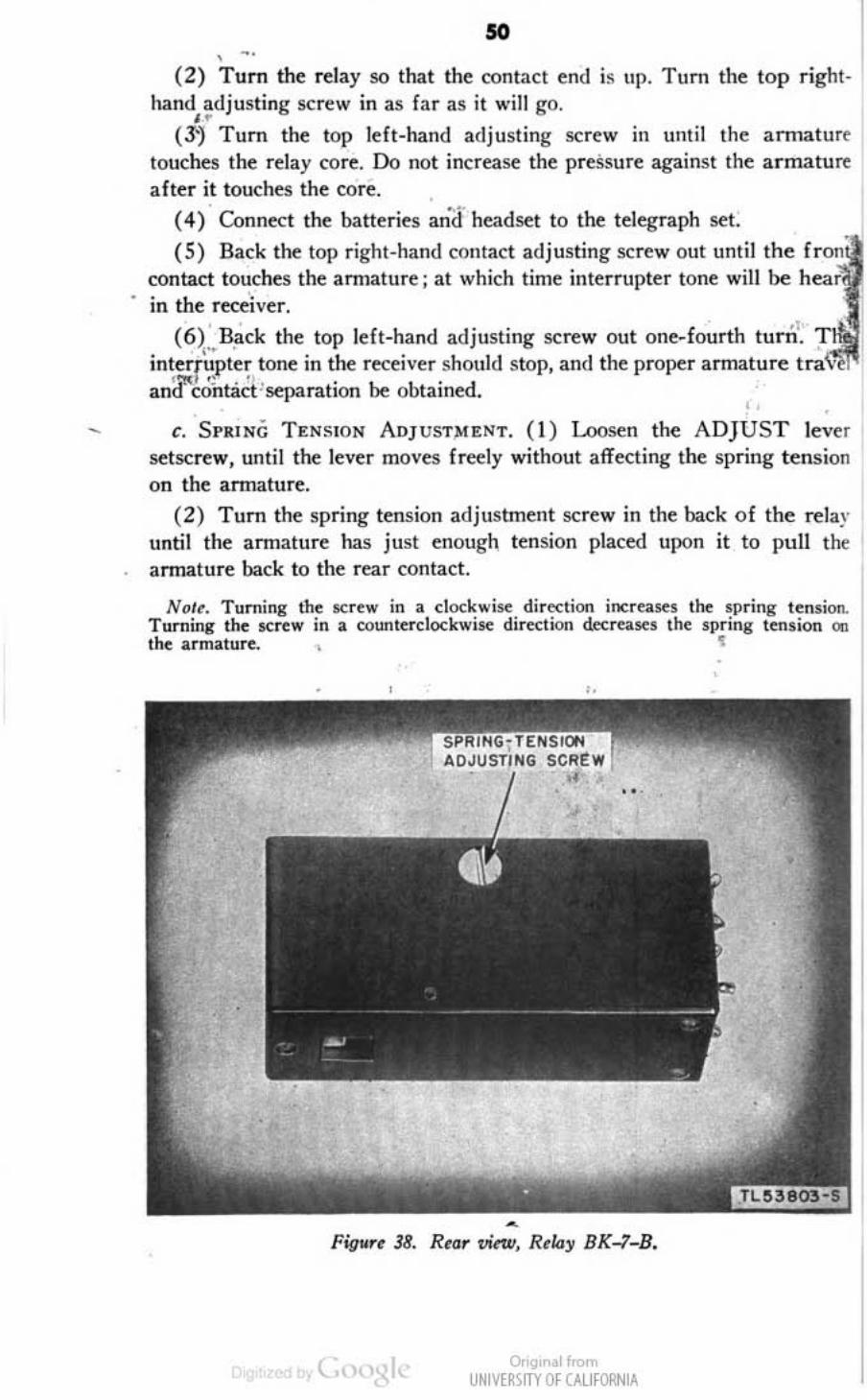
50 , -.
(2) T um the relay so tha t the contact end is UI). Tum the top r ighthand adjusting screw in as far as ;1 will go . . '
(3J Turn the top left-hand adjusting screw in until the amlaturt touches the rclay core. Do not increase the pressure against the ar mature after it touches the core. .
• • ••• (4) Connf:Ct the batteries ani;! headset to the telegraph set.
( 5) Back the top right-hand contact adjusting sc~w out until the contact touches the amJature ; at which time interrupter tone will be h,,, in the rece'iver.
• • .1 (6)".Back the top left-hand adjusting screw out one-fourth turn.
interrupter lone in the receiver should stop, and the proper armature 'tit " " and cohtact ' separation be obtained. ,
• - t. SPRING TENSION AOJ UST>U:N T. (I) Loosen the ADJUST lever
setscrew, unti l the: lever moves freely without affecting the spring tens ion on the annature.
(2) Turn the spring tension adjustment screw in the back of the rela)· until the annature has just enough tension placed Upon it to pull tilt armature back to the rear contact.
Nol~. Tuminll the t;<;rew in a clocK"';se dir~tion increases the sprinll tension. T l1rTIing the sen .... in a oounterdOCKwise dir~tion decreases the spring tension 01:1 the armature. , ~
Fig .. ., 38. Rtar vin.v, Rtlay 8K"';-B.
OOgtr •• 1 If"", UNIVE~\lTY Of CAlifORN IA

•
"
Figlirt 19. Cimtad ~ruJ, RtI"l' BK-l-B.
(3) Sd the ADJUST lever 10 0, and tighten the setscrew. Be careful when tightening the setscrew not to change the spring tension.
d, REI'I .... CEME"T OF RELAY. ( 1) Replace the bakelite cover and screws which hold it in place,
(2) Replace the metal contact COVH,
(3) Place the relay on the relay mounting bracket .
' (4) Replace the four sc~ws in the bottom of the ~lay.
61. Burnishing and Adjusting Contacts of Jack JK-3S
a. AOJUSTMENT OF J ACK CONTACTS. ( 1) Remove the jack. (~par. 52. )
(2) Bend the tip contact of the jack so that it rests firmly upon the phenolic spacer that is sc:cuT('d to the metal basc:o
(3) Adjust the H031 contact so that it rests firmly upon the phenolic spacer on the top of the tip contact. Do not put sharp bends in the contact springs.
( 4 ) Bend the break contact up until it touches the Roat contact and forces the float contact off the phenolic spacer just enough to see light under it.
(5) Adjust the make contact so that a Clearance equal to the thickness of the screw driver end of Kni fe TL-29 is attained between the make and Roat contacts.
(6) Insert the plug in the jack and check the operation of the jack. The
Or'9' .11<om UNIVERSITY Of CALIfORNIA
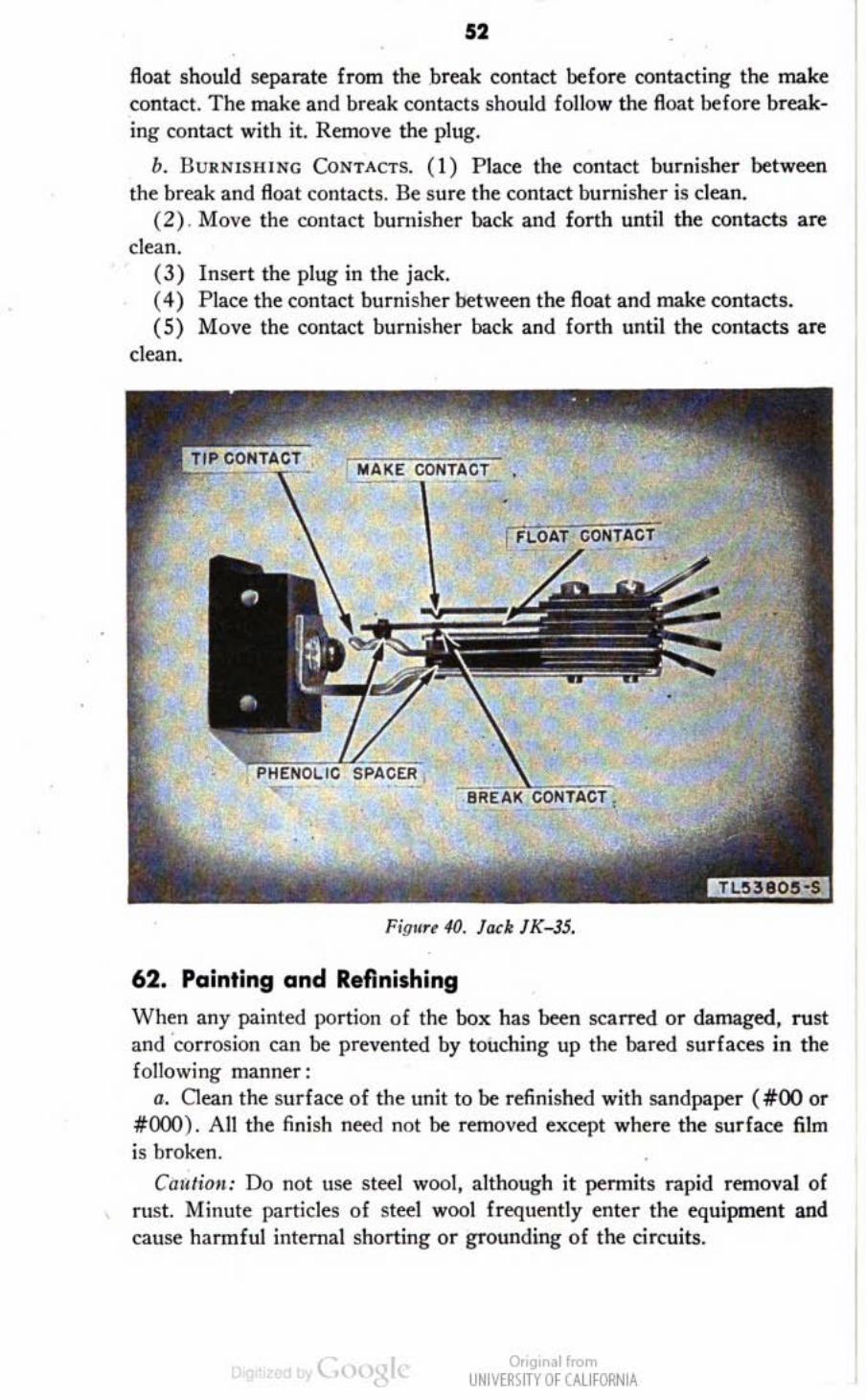
•
52
float should separate from the break contact before contacting the make contact. The make and break contacts should follow the float before breaking contact with it. Remove the plug.
b. BmlNlSIIING CoNTACTS. (I) Place the contact burnisher between the break and float contacts. Be sure the contact burnisher is clean.
(2) . Move the contact burnisher back and forth unti1 the contacts arc clean.
(3) Insert the plug in the jack. (4) Place the contact burnisher between the float and make contacts. (5) Move the contact bumis~r back and forth until the: contacts are
clean .
FigNr~ 40. lad: JK-J5,
62. Painting and Refinishing
When any painted portion of the box has been scarred or damaged, rust and 'corrosion can be prevented by touching up the bared surfaces in the following manner:
a, Oean the surface of the unit to be refinished with sandpaper (#00 or #000). An the finish need not be removed except where the surface film is broken.
Cal, timl: Do not use steel wool , although it pennits rapid removal of rust. Minute particles of steel wool frequently enter the equipment and cause harmful internal shorting or grounding of the circuits.
0.'9' .11<om UNIVE~SITY Of CALIfORNIA

53
b. Spray two coats of enamel, olive-drab, low-gloss. ai r-drying (stock No. 6(428), or ~uaJ, on the case. Air-dry between applications.
63. Unsatisfactory Equipment Report
II. When trouble in equipment used by Army Ground Forces or Army Service Forces occurs more often than repair personnel fed is "onnal, War Department Unsatisfactory Equipment Report, WD AGO Form 468
EOUIf'MENT IEPOIII
.... -....... ..-..-_ .. _ .... _-_.-_._ .. _--_._. __ . ..._-. _-_ ........ - ._. . ------_. , ._._-_ .... .-. _--_ .. _-----_. ,,,._--_ .... _._- , ._--- ' ... , .. '-- ,
_.----_.-. 'I' ___ ...... -._. 7 ... _.- -_ .. .. _._ ... __ ... _- ,.. ..
. ~ __ ~. ~_~._M."""_." __ .... __ .... _ .. _ ........ __ ---' '-- -_ ....... _-_ .. _ .. - .... -. -.- ---- ._-._--_ .. _.. -.-~-- .. -.. --.. -- _. -, --_ .. _ .. _--.. - -._-_ .. __ ._ .. _---- --_ .. __ .... _---_ .. -._-_ ... _-:.:.:-::-:-:-:.:-:' .. :":"'------
0.'9. ~11n>m UNIV[RlfTY Of CALIfORNIA

54
(fig. 41). should be filled out and forwarded through channels to the Office of the Cbid Signal Officer, Washington 25, D. C.
b. When trouble in equipment used by Anny Air For~s occurs more often than repair personnel feel is normal, Army Air Forces Form 54 should be filled out and forw3rded through channels.
c. If either form is not available, prepare the data according to the sample form reproduced in figure 41.
•
. ,
•
0.'9' ~11n>m UNIV[RlfTY Of CALIfORNIA
•

" APPENDIX I
MAINTENANCE PARTS
The following information was compile.! on 1 April 1945. The al)propriate sections of the ASF Signal Supply Catalog for Telegraph Sct TG- 5-(·) are:
SIG 7- TG-S. Organi~ationa! Spare Parts for Tckgraph Set TG-5. SIG 8-TG-5, Higher Echelon Spare Parts for Telegraph Set TG- 5-( ).
For the latest index of availahle calaif)g sections, see ASF Signal Supply Catalog SIG 2.
.. !;i,Mr CO<f>O s.'"~ "m~ It .... No.
--Fig. , 4A2805A1S OUKN1SHER
Fig. , 2BII32 HEADSET H"-W
FlELL Fig. 5 Fig. 35 CAPACITOR
CA-21O.
Fig. I 4AJ(9A CASE CS-4'h \
Fig. , 4A280Slljl2 CATCH, front
Fig. , 4A2805B/28
Fig. , 4Z5007 ( )
Fig. 4{l n55J5 Fig. 5 JZ3441A Fig. 5 4A20078 Fig. 5 229405.22
4A2005/49
"" SO,.,I COO-I>< S.m. .ymbol otook No.
---6LJI02-56 NUT, bell
6l31Q4.-4(l mounting.
NU,T, capa_ cllor mounting.
61.0256-3.59 SCREW, catch
6L6256-3.5A mountinr·
SCREW, bell
6L6256--5,7AO mounling.
SCREW, be ll mounting.
Onq, ol",,", UNIVtl1'im Of UlJfORN lA

.. APPENDIX II
REFERENCES
1. Army Regulations
AR 380-5, Safeguarding Military Information.
2. Parts Lists
SIG 1. SIG 2, SIG 3, SIG 4-1, SIG 4-2,
SIG S, SIG 6. SIG 7-TG-S, SIG 8--TG-5,
SIG 10,
SB 11-6,
Introduction to ASF Signal Supply Catalog. Complete Index to ASF Signal Supply Catalog. List of Items for Troop Issue. Allowances of Expendable Supplies. Allowances of Expendable Supplies for Schools,
Training Centers, and Boards. Stock Lis! of all Items. Sct~ and P & I Control List. Organizational Spare Parts for Telegraph Set T G-S. lIigher Echelon Spare Paris for Telegraph Set
TG-( ). Signal Supply Cata!Q<,;' Fixed Plant Maintenance
Lists. Dry Battery Supply Data.
3. Technical Manuals on Test Equipment
TM 11 - 2017, Test Set TS-26/TSM. T M 11- 2613, Voltohmmeter 1-166.
4. Painting, Preserving, and lubrication
TB SIG 123. Preventive Maintenane<: Practices for Ground Signal Equipment.
5. Shipping Instrudions
u.s. Army spec No. lOO-I4A. Army-Navy General Specifications for Packaging and Packing for Oversea shipment.
6 . Deeontaminalion
TM 3-220, Deumtamination.
Onq, ollron> UNIVtl1'im Of UlJfORN lA

7. Demolition FM 5-25, Explosives and IXmolit ions.
8. Camouftage FM 5-20, Camouflage, Basic Principles.
9. Oth.r Technical Publicotions FM 21-6, List of Publications for Training. FM 21- 7, List of War Department Films, Film Strips, and Re<:og·
nition Film Slides. FM 21-8, Military Training Aids. FM 21-40, Defense Against Chemical Attack. FM 24-5, Signal Communication. TB SIG 13. Moistureproofing and Fungiproofing Signal Corps
Equipment. TB S IG 29, Impedance Unbalance Tests for Coils C-161 and e-
228. TB SIG 37, Grounding Requirements and Procedure Applicable to
\Vire Communication and Associated Electrical Apparatus. TB SIG 66, Winter Maintenance of Signal Equipment. TB S IG 69, Lubrication of Ground Signal Equipment. TB SIG 72, Tropical Maintenance of Ground Signal Equipment. TB SIG 75, Desert Maintenance of Ground Signal Equipment. TB SIG 96, Repair Instructions for Field and Long Range Tactical
Wire. TB SIG 101, Longe-range Tactical Wire W-143. TB SIG 121, Instructions for Tying and Use of Weave Tie for
Field Wires and Cables. TD S IG 123, Preventive Maintenance Practice {or Ground Signal
Equipment. TB SIG 150, Wire Dispenser MX-JOl/G. TB 11-430-1, ?o.Iain tenance of Batteries in Nontemperate Areas. TM 1-455, Electrical Fundamentals. TM 11--430, Batteries for Signal Communication Except Those Per-
taining to Aircraft. TM 11--432, Code Practice Equipmeot. TM 11-450, Trainiog of Signal Communication Personoel. TM 11-456, Wire Telegraphy. TM 11-459, Instructions for Learning International Morse Code
Characters. TM II 462, Signal Corps Reference Data. TM 11-498, Fundamentals of Telephony and Ma'lual Telegraphy. TM 37-250, Basic Maintenaoce Manual.
Onq, ollron> UNIVtl1'im OfUUfORNlA

51
10. Forms
WD AGO Form 468, Unsatisfactory Equipment Report. AA F Form 54, Unsatisfactory Report.
11 . Abbreviation.
AAF ................... • ...... ..... Army Air Fon::es AGO ......................... ...... Adjutant General's Office ASF ........... • ..... . ..... . ....... . Anny ~rvice Forces d-c ...... . ....... . ..... • .. . . ..... . .. direct-curren t fig .............. • ..... • ...... .. .... . figure mf .......... • ..... • ..... ••......... microfarad No ............ .• .....•............ . .number 113 r. . . . . . . . . . . • . . . . . • . . . . . . • . . . . . . . . pa ragra ph revr ...... ... .......... • ............ rece1ver SI)I)C .•.• • .••.••••••••••••.•••••••••• specification subpar . .... ... . , .... . •. ... . ......... subparagraph tfOrm ..........•.. •• .... • ..• . •..• ..•• teoninal v .... . .. . ...... . . ,. " . ,".,', .. ,. ,' ,volt ( s) wo . .. ...... . ,., ,. ' •... .... .. .. . . ,. W ar Department xmtr , .. , .. , . , • .... .• . . ...•. . . . .. ... ,transmitter
,
* u. s. c:o..m",.,.' P';nt;~1 01&.: IIHS-428(1Zl
( )0 I :),'9' ... ' .... UNIV[~\ITY Ill' ~NlA
I