r&d technical report w84 a godley - environmentdata.org
TRANSCRIPT

Abstraction Metering Good Practice Manual
R&D Technical Report W84
A Godley
Research Contractor: WRc plc

The Environment Agency, Rio House, Waterside Drive, Aztec West, Almondsbury, Bristol, BS12 4UD
www.environment-agency.gov.uk
Tel: 01454 624400 Fax: 01454 624409
© Environment Agency 2002
All rights reserved. No part of this document may be reproduced, stored in a retrieval system, or transmitted, in any form or by any means, electronic, mechanical, photocopying, recording or otherwise without the prior permission of the Environment Agency.
The Environment Agency, its officers, servants or agents accept no liability whatsoever for any loss or damage arising from the interpretation or use of the information, or reliance upon views contained herein.
Dissemination status Internal: Released to Regions External: Released to Public Domain
Statement of use This document is to be used by the Environment Agency staff as a Good Practice Manual for abstraction metering.
Research contractor This document was produced under R&D Project 660 by:
WRc plc Frankland Road, Blagrove Swindon, Wiltshire, SN5 8YF Tel: 01793 865000 Fax: 01793 865001
Environment Agency Project Leader The Environment Agency’s Project Leader for R&D Project 660 was Paul Crockett, Environment Agency, Midlands Region. Ownership of the Manual within the Agency currently lies with Wendy Rogers, Southern Region.
Amendments Any corrections or proposed amendments to this manual should be made through the regional Agency representative on the Water Resources National Abstraction Licensing Group.
R&D Technical Report W84 Further copies of this report are available from:Environment Agency R&D Dissemination Centre, c/oWRc, Frankland Road, Swindon, Wilts SN5 8YF
tel: 01793-865000 fax: 01793-514562 e-mail: [email protected]

Document Control Abstraction Metering Good Practice Manual
R&D Technical Report W84 (i) Version 3.1 February 2002
DO
CU
ME
NT
CO
NT
RO
L
Rev
isio
n st
atus
Am
endm
ent
Num
ber
Am
endm
ent
Dat
eR
evis
ion
Par
tSe
ctio
nP
age
Inco
rpor
ated
byD
ate
2/2/
96D
raft
30/4
/96
1.0
(Int
erim
)A
ll
20/1
2/96
2.0
(Dra
ft F
inal
)A
ll
28/8
/97
3.0
(Fin
al)
All
1Fe
brua
ry 2
002
Febr
uary
200
2
3.1
3.1
6 App
. D
6.4-
6.5
All
2A
ll
6-16
- 6-
18

Abstraction Metering Good Practice Manual Document Control
Version 3.1 February 2002 (ii) R&D Technical Report W84
This page is left blank intentionally

Contents Abstraction Metering Good Practice Manual
R&D Technical Report W84 (iii) Version 3.1 February 2002
CONTENTS Page
HEALTH AND SAFETY NOTE (vii)
GLOSSARY (ix)
1. INTRODUCTION 1-1
1.1 Objectives 1-1 1.2 The need for abstraction measurement 1-1 1.3 Requirements for abstraction measurement 1-2 1.4 Layout of manual 1-3 1.5 Application of recommendations 1-4
2. ABSTRACTION CATEGORIES 2-1
2.1 Summary of statistics 2-1 2.2 Domestic and Agriculture 2-2 2.3 Spray Irrigation 2-2 2.4 Industrial and Commercial 2-3 2.5 Electricity Generation 2-4 2.6 Public Water Supply 2-5 2.7 Other uses 2-6
3. GENERAL GUIDANCE 3-1
3.1 Performance 3-1 3.2 Meter sizing 3-3 3.3 Water source 3-4 3.4 Security of data 3-5 3.5 Maintenance and checking 3-7 3.6 Economic factors 3-10 3.7 Meter inspection 3-10 3.8 Licence conditions 3-12 3.9 Current standards 3-12
4. METERING METHODS 4-1
4.1 Introduction 4-1 4.2 Differential pressure methods 4-2 4.3 Other differential pressure methods 4-5 4.4 Positive displacement flowmeters 4-6

Abstraction Metering Good Practice Manual Contents
Version 3.1 February 2002 (iv) R&D Technical Report W84
4.5 Turbine and jet types 4-8 4.6 Fluid oscillatory types 4-12 4.7 Electromagnetic flowmeters 4-13 4.8 Ultrasonic flowmeters 4-17 4.9 Insertion meters 4-20 4.10 Methods for partially filled pipes 4-24 4.11 Assessment methods 4-25 4.12 Totalisers 4-26 4.13 Summary of characteristics 4-27
5. METER INSTALLATION AND LOCATION 5-1
5.1 Installation 5-1 5.2 Flow conditions 5-7 5.3 Location 5-8
6. FLOW CHECKING AND METER CALIBRATION 6-1
6.1 Introduction 6-1 6.2 In situ methods 6-5 6.3 Laboratory methods 6-15 6.4 Electromagnetic meter verification tools 6-16 6.5 Buried meters 6-16 6.6 Verification of data transmission and recording 6-18 6.7 Remedial action 6-19
REFERENCES AND BIBLIOGRAPHY
APPENDIX A - Flow Conversion Tables
APPENDIX B - Existing Installation Assessment
APPENDIX C - Photographs of Flowmeters and Installations
APPENDIX D - Suppliers of Metering Equipment and Calibration Services
ABSTRACTORS SUMMARY SHEETS
Information for Domestic and Agricultural Licence Holders
Information for Spray Irrigation Licence Holders
Information for Industrial and Commercial Licence Holders (including Electricity Generation)
Information for Public Water Supply Licence Holders

Contents Abstraction Metering Good Practice Manual
R&D Technical Report W84 (v) Version 3.1 February 2002
LIST OF TABLES
Table 2.1 - Breakdown of licences 2-1
Table 3.1 - Performance types from WIS 7-03-01 3-14
Table 4.1 - Applicable meter types 4-1
Table 4.2 - Summary of measurement methods in part filled pipes 4-25
Table 4.3 - Recommended totaliser precision 4-27
Table 4.4 - Summary of characteristics of closed pipe flowmeters 4-28
Table 5.1 - Severity of flow disturbance 5-2
Table 5.2 - Distances of flowmeter from sources of disturbance 5-3
Table 5.3 - Summary of IP ratings from IEC 529 5-11
Table 6.1 - Key to meter types in Table 6.2 6-2
Table 6.2 - Intervals for flow checking (in years of use) 6-3
Table 6.3 - Distances from meter when using an insertion probe 6-9
Table 6.4 - Distances from meter for using a clamp-on 6-11
Table 6.5 - Flow checking with a clamp-on ultrasonic flowmeter 6-12
Table 6.6 - Remedial actions 6-19
LIST OF FIGURES
Figure 1- Pipe dimensions ix
Figure 2- Example of a flowmeter performance graph showing various key points xii
Figure 3- Fully developed velocity profile xiii
Figure 4- Velocity profile downstream of a bend xiii
Figure 3.1 - Example of accuracy expressed as per cent reading and per cent full scale 3-1
Figure 3.2 - Relationship between accuracy and repeatability 3-2
Figure 4.1 - Typical Venturi installation 4-4
Figure 4.2 - Differential pressure transducer 4-5
Figure 4.3 - Variable area flowmeter 4-6
Figure 4.4 - Rotary piston meters 4-7
Figure 4.5 - Typical Woltmann meter 4-8
Figure 4.6 - Typical combination meter 4-10
Figure 4.7 - Irrigation meters 4-11
Figure 4.8 - Fluidic oscillator 4-13

Abstraction Metering Good Practice Manual Contents
Version 3.1 February 2002 (vi) R&D Technical Report W84
Figure 4.9 - Electromagnetic flowmeter 4-13
Figure 4.10 - Operating principle of an electromagnetic flowmeter 4-14
Figure 4.11 - Earthing an electromagnetic flowmeter 4-16
Figure 4.12 - Ultrasonic Doppler flowmeter 4-17
Figure 4.13 - Transit time ultrasonic flowmeter 4-18
Figure 4.14 - Electromagnetic insertion probe 4-20
Figure 4.15 - Alignment of insertion probes 4-21
Figure 4.16 - Averaging pitot tube 4-23
Figure 4.17 - "Watering can" meter for part filled pipes 4-24
Figure 4.18 - Typical totaliser display 4-26
Figure 5.1 - Poorly fitted gaskets can cause flow disturbance 5-1
Figure 5.2 - Always install electromagnetic meters downstream of pumps 5-2
Figure 5.3 - Bad and good installation practice 5-4
Figure 5.4 - Designs of flow straightener 5-5
Figure 5.5 - Vertical installation 5-5
Figure 5.6 - Installation of electromagnetic and ultrasonic instruments 5-6
Figure 5.7 - Installing the meter to maintain a full pipe 5-6
Figure 5.8 - Suitable and unsuitable meter locations 5-7
Figure 5.9 - Avoid installation in direct sunlight 5-9
Figure 5.10 - Avoid sites where chemical leaks or spillage may occur 5-9
Figure 5.11 - Avoid positions where vibration may be present 5-10
Figure 5.12 - Meter should be supported 5-10
Figure 6.1 - Examples of how to include a transfer standard 6-7
Figure 6.2 - Reservoir drop test 6-8
Figure 6.3 - Testing with an insertion meter 6-10
Figure 6.4 - Thermodynamic method 6-13
Figure 6.5 - Tracer dilution method 6-14

Health and Safety Abstraction Metering Good Practice Manual
R&D Technical Report W84 (vii) Version 3.0 August 1997
HEALTH AND SAFETY
IMPORTANT NOTE
This manual contains procedures which may have to be applied in hazardous situations. The requirements of the safety policies of the Environment Agency and the abstractor must be observed at all times. The following have been identified as potential hazards:
• working with electricity
• working near water
• confined spaces
• lone working
• pipelines under pressure
• lifting heavy objects, e.g. drain covers
• chemicals (e.g. tracers or cleaning/disinfection agents).
Further guidance may be found in the following Agency documents:
• Environment Agency Management Safety Standards No 3.2.1 Confined Spaces
• Environment Agency Management Safety Standards No 3.2.3 Control of Substances Hazardous to Health (COSHH)
• Environment Agency Management Safety Standards No 3.2.8 Lone Working
• Environment Agency Management Safety Standards No 3.6.5 Working in or near Water
Where the rules of the abstractor differ from those of the Environment Agency, the more stringent code shall be followed.

Abstraction Metering Good Practice Manual Health and Safety
Version 3.0 August 1997 (viii) R&D Technical Report W84
This page is left blank intentionally

Glossary Abstraction Metering Good Practice Manual
R&D Technical Report W84 (ix) Version 3.0 August 1997
GLOSSARY
More complete explanations of some of these terms can be found in the main text. The relevant section number is given in brackets where this is the case.
Accuracy - Qualitative assessment of the reading given by an instrument compared to the true value over a defined range of flows (Section 3.1.1).
Bi-directional - Measures flow passing through the meter in either direction.
Bore - Internal diameter (i.d.) of pipe, see Figure 1.
Calibration - Determination of the relationship between flow rate and reading which may include mechanical or electrical adjustments to produce a desired characteristic.
Cavitation - Release of gas dissolved in the fluid or vaporisation of the fluid due to the local static pressure dropping below the vapour pressure of the fluid.
Liner (if present) Pipe wall
Wall thickness
Liner thickness
Internal diameter (i.d.)
Outside diameter (o.d.) Figure 1 - Pipe dimensions

Abstraction Metering Good Practice Manual Glossary
Version 3.0 August 1997 (x) R&D Technical Report W84
Combination meter - Meter which comprises a main meter, usually a Woltmann type, with a smaller meter mounted in a by-pass, with an integral valve to divert flow through whichever meter is appropriate for the flow rate (Section 4.5.2).
Conductivity - The ability of a fluid to pass an electric current, commonly expressed in micro-Siemens per centimetre (µS/cm).
D (diameter) - Nominal bore (internal diameter) of a pipe, see Figure 1. Multiples of pipe diameters are a useful dimension for specifying pipe lengths, e.g. for the distance between a flowmeter and a fitting.
Differential pressure cell - Device for measuring the difference in pressure between two points (Section 4.2.2).
Electromagnetic flowmeter - Flowmeter which utilises the Faraday effect, i.e. an electromagnetic field is generated across the pipe and the movement of a conductive fluid, e.g. water, through the field causes a voltage to be produced which is measured and used to calculate flow rate (Section 4.7).
Error - Difference between a single measured value and the true value, often expressed as a percentage of the true value.
Flowmeter - Device which measures either the rate at which fluid is flowing past a certain point or which gives the total amount of fluid which has passed a certain point in a known time.
NOTE: In this report, the term flowmeter, or meter, is taken to include the flow sensor and any associated secondary device, electronics or automatic data recording device.
Flow checking (Verification) - Testing whether a meter is reading to the desired accuracy by comparing its readings with those obtained simultaneously by another method or meter of known accuracy.
Flow rate - Quantity of fluid passing a particular point per unit time.
Flow straightener - Device placed in the flow to help recover a fully developed velocity profile (see below) after a source of disturbance (Section 5.1.3).
Full scale - The maximum flow rate that the flowmeter will read to a specified accuracy.
Head loss - A measure of the energy required for the fluid to pass through obstructions and fittings in a pipe, expressed as a drop in pressure.
Helix meter - See Woltmann meter.
Impeller meter - See Woltmann meter.
Insertion flowmeter - Flowmeter which is inserted through the wall of a pipe via a gland (Section 4.9).

Glossary Abstraction Metering Good Practice Manual
R&D Technical Report W84 (xi) Version 3.0 August 1997
In-situ - Without removing the instrument from the pipeline.
Integrator - See Totaliser
Jet meter - Flowmeter where the fluid is forced through one or more small orifices onto the blades of a rotor (Section 4.5.3).
Local or point velocity - The fluid velocity at a discrete point in the flow.
Mean axial velocity - The volumetric flow rate divided by the cross sectional area at the point of measurement.
Multimeter - Instrument for measuring electrical currents and voltages.
National Standard - The National Standard flow rig is at the National Engineering Laboratory (NEL) in East Kilbride. It can trace its measurement of the mass of water passed directly to the National Standard kilogram. By definition, it is the most accurate test rig in the UK against which other rigs should be compared.
Non-intrusive - Meter has no parts intruding into the flow and hence causes minimal disturbance and head loss.
Oscilloscope - Instrument for measuring electrical voltages and displaying the wave form on a screen.
Positive displacement flowmeter - Meter which divides the fluid up into discrete, known quantities (Section 4.4).
Primary device - A device which generates a signal enabling the flow rate to be determined.
Q - Flow rate, often used with a suffix to indicate particular flow rates, see Figure 2:
Qmin - the minimum flow rate that an instrument can measure to the maximum specified error.
Qmax - the maximum flow rate at which the flowmeter will operate for short periods of time without deteriorating.
Qt - the transitional flow rate, i.e. the rate at which the maximum permissible error changes in value
Qn - the nominal flow rate of a flowmeter.
Repeatability - The ability of an instrument to record the same value for the same flow under the same conditions in a short period of time (Section 3.1.3).

Abstraction Metering Good Practice Manual Glossary
Version 3.0 August 1997 (xii) R&D Technical Report W84
Reproducibility - The ability of an instrument to record the same value for the same flow over the long term.
Secondary device - A device which receives a signal from the primary device and displays, records, converts and/or transmits it as a measure of flow.
Strainer - Device placed in the flow to remove weed, gravel and other debris (Section 5.3.5).
Swirl - A component of flow which is rotating around the longitudinal axis of a pipe.
Totaliser (Integrator) - Device which records the total quantity of liquid to have passed through the meter. This may be integral to the meter or a separate unit (Section 4.12).
Transfer Standard - A flowmeter calibrated to a known uncertainty against which another flowmeter can be compared (Section 6.2.1).
Flow rateQmin Qt QmaxQn
Erro
r as
per c
ent m
easu
red
valu
e
10
5
2
0
-2
-5
-10
Figure 2 - Example of a flowmeter performance graph showing various key points
Turbine flowmeter - Flowmeter which has a rotor mounted in the flow (Section 4.5).
Turndown - Ratio of the maximum and minimum flows measurable by a device to a stated uncertainty.
Ultrasonic flowmeter - Flowmeter which operates using pulses of ultrasound (Section 4.8).

Glossary Abstraction Metering Good Practice Manual
R&D Technical Report W84 (xiii) Version 3.0 August 1997
Uncertainty - Band around the measured value within which the true value lies with a stated probability, usually 95% (Section 3.1.1).
Uni-directional - Measures flow in one direction only.
Velocity profile (Sometimes referred to as “flow profile”) - The distribution of point velocities over the cross section of the flow. Frictional forces between the flowing fluid and the pipe wall will slow down the fluid close to the wall so that it has a lower velocity there than the centre of the pipe. The operation of the types of flowmeters likely to be used for abstraction purposes assume that the velocity profile on inlet to the meter will be what is known as “fully developed”, see Figure 3. Deviations from this shape caused by bends, Figure 4, valves and other fittings are likely to cause inaccuracies in the flowmeter reading amounting to several per cent.
Figure 3 - Fully developed velocity profile
Figure 4 - Velocity profile downstream of a bend

Abstraction Metering Good Practice Manual Glossary
Version 3.0 August 1997 (xiv) R&D Technical Report W84
Verification - See Flow checking
Volumetric flow - The volume of fluid passing a certain point per unit time.
Woltmann meter - Type of turbine meter with a helical rotor (Section 4.5.1).

Introduction Abstraction Metering Good Practice Manual
R&D Technical Report W84 1-1 Version 3.0 August 1997
1. INTRODUCTION
1.1 Objectives
This Manual is intended for use by Environment Agency (the Agency) licensing and enforcement staff, as well as by abstractors. It covers the measurement by meter of water in closed conduits which has been abstracted under licences administered by the Agency. It does not include open channel measurement methods such as weirs and flumes which are outside the terms of reference for this manual.
The manual has the following main objectives.
• To provide guidelines on abstraction measurement, which are common across all regions of the Agency;
• To instruct Agency licensing and enforcement staff on good practice for metering water abstraction. This applies both to new applications and to existing installations;
• To provide a reference work for abstractors, manufacturers, fabricators, installers and contractors;
• To recommend appropriate accuracy standards for all types of abstraction measurement; and
• To improve the standard of accuracy of abstraction measurement.
The manual has been compiled using data from many sources, including existing Agency documents, British Standards, site visits, technical books and papers as well as consultation with abstractors, equipment manufacturers, Trading Standards and Agency staff.
Chapters 8 and 9 of the Agency Licensing Manual1 give details of licence conditions, inspection and enforcement. This manual provides the link between the licence conditions and the practicalities of metering.
1.2 The need for abstraction measurement
The principal reason for measuring the quantity of water abstracted is to allow the Agency to effectively manage this nation’s raw water resources. This is done through a system of licensing whereby those that need to take water from a source apply to the Agency for a licence to abstract. The licence will impose conditions such as the quantity of water allowed to be removed over a certain period or the rate at which it can be taken, sometimes a combination.

Abstraction Metering Good Practice Manual Introduction
Version 3.0 August 1997 1-2 R&D Technical Report W84
Reliable metering is essential to provide a record of how much water is taken. This enables the Agency to ensure that:
• resources are not over abstracted;
• spare resources can be allocated to new abstractors;
• equitable payments for abstraction can be set;
• licence conditions are complied with; and
• it can provide accurate statistical data required by the Department of the Environment.
1.3 Requirements for abstraction measurement
The provision and operation of a flow measurement device is the responsibility of the licence holder with the Agency approving the type, size, installation and subsequent calibration.
The flow measurement equipment must meet the needs of both abstractors and the Agency. The main requirements of abstraction metering equipment are summarised below.
Requirements of abstractors
• low purchase and installation cost i.e. low cost of ownership
• high reliability and low maintenance cost
• meets the conditions of the licence to the satisfaction of the Agency
• provides appropriate data to satisfy the needs of the abstractor and the Agency
• easy to read
• has a low head loss (for many applications)
• availability of maintenance and repair facilities
Requirements of the Agency
• meets the conditions of the licence
• records flows to an acceptable accuracy
• robust and reliable
• easy to read
• protected from fraud

Introduction Abstraction Metering Good Practice Manual
R&D Technical Report W84 1-3 Version 3.0 August 1997
• ease of inspection of the meter and surrounding fittings
• ease of verifying the recorded flow
Many of these needs are common to both parties though the priorities may be different. Low cost of ownership and minimal interference with flow are probably of greatest importance to most abstractors. Reliability and accuracy are of most immediate importance to the Agency, with ease of access, inspection and verification being the principal needs of enforcement officers.
The metering requirements of each abstraction must be dealt with on an individual basis and are dependent on local site conditions.
This manual gives guidance on the factors which need to taken in account such as:
• type of meter;
• size of meter;
• location of meter;
• flow rates;
• surrounding pipe layout and orientation;
• water source;
• category of abstraction;
• meter installation;
• security of data and source;
• safety; and
• cost.
1.4 Layout of manual
The main text of the manual is divided into five sections:
• Section 2 - Abstraction Categories - Once abstracted the water is used for various purposes which may be split into a number of categories. Certain features of each category are discussed in the context of metering their abstractions.
• Section 3 - General Guidance - This section is intended to give general guidance on a number of key issues which will affect the selection and operation of a flowmeter used for abstraction metering.

Abstraction Metering Good Practice Manual Introduction
Version 3.0 August 1997 1-4 R&D Technical Report W84
• Section 4 - Metering Methods - This section covers all meter types likely to be found monitoring abstractions and discusses their working principles, advantages, disadvantages and applicability to different types of abstraction. It also includes a section on totalisers.
• Section 5 - Meter Installation and Location - Poor installation is one of the main causes of flowmeters giving poor readings. This section highlights the key issues and describes good (and bad) practice.
• Section 6 - Flow Checking and Meter Calibration - This section describes the options available for carrying out flow checks on a meter in-situ or in a laboratory.
The main text is supported by appendices giving:
• A - Flow conversion factors;
• B - Criteria for site assessments;
• C - Examples of meters and installations; and
• D - Equipment suppliers.
The second part of the manual comprises a number of summary sheets which are specifically aimed at the abstractors. These summarise the requirements of measurement for each category of abstraction, i.e.
• Domestic and Agriculture;
• Spray Irrigation;
• Industrial and Commercial (including Electricity Generation); and
• Public Water Supply.
1.5 Application of recommendations
Agency policy and the wording of individual licences will determine to what extent the recommendations are applied on existing and new abstraction sites.
The guidance in this Manual applies to normal circumstances; exceptional or unusual conditions may preclude their use. However, Agency staff will be provided with advice to allow them to make informed decisions in such circumstances.

Abstraction Categories Abstraction Metering Good Practice Manual
R&D Technical Report W84 2-1 Version 3.0 August 1997
2. ABSTRACTION CATEGORIES
2.1 Summary of statistics
There are over 48 000 abstraction licences in force at the time of writing (1996). These may be split into a number of categories depending on the use to which the water taken is put. Table 2.1 summarises the breakdown between the different categories of abstraction in terms of:
• the quantity of water licensed for each category as a proportion of the total across all Agency regions2;
• the number of licences issued for each category as a proportion of the total across all Agency regions3;
• the proportion of licences in each category that include a statement requiring a meter to be used3; and
• the proportion of licences in each category classified as large3, i.e. over 20m3/day.
Table 2.1 - Breakdown of licences
Abstraction Category
Proportion of licensed quantity
Proportion of licences
Proportion requiring a
meter
Proportion of large
abstractions
Domestic and Agriculture
<1% 57.2% 35% 45%
Spray Irrigation <1% 24.0% 69% 82%
Industrial and Commercial
12% 9.9% 62% 77%
Electricity Generation
36% 0.1% 33% 100%
Public Water Supply
51% 4.3% 93% 92%
High Volume Non-consumptive and other
non-consumptive
4.5% 23% 99%

Abstraction Metering Good Practice Manual Abstraction Categories
Version 3.0 August 1997 2-2 R&D Technical Report W84
2.2 Domestic and Agriculture
This covers the metering of abstractions for domestic (household) supplies to individual properties or estates (sometimes referred to as “private water undertakings”) and all agricultural uses, except for spray irrigation (see Section 2.3). Typical uses in this category are:
• drinking, washing and cooking in houses or small groups of houses, often in remote areas;
• general farm duties;
• nursery use;
• filling a reservoir in winter to meet periods of high demand;
• cleaning sheds and equipment; and
• stock watering (the major use in this category).
Whilst the quantity of water taken by this category of use is small and rates of abstraction are low as compared with some other categories, it accounts for over half of licenses issued. Installations will usually be owned and operated by farmers and others without specialist metering knowledge.
Many licenses currently base the abstraction quantity on numerical estimations, for example head of cattle on a specified day of the year or number of houses supplied. This method is far from ideal; it is extremely difficult to verify, making it open to abuse, and provides poor quality data on which to base resource management decisions.
As the majority of these abstractions are small, i.e. pipe sizes ½” to 1½” (15mm to 40mm), and often on remote sites away from mains power, it is predominantly mechanical meters that are used.
An abstractors’ summary data sheet which summarises the requirements for the metering of domestic and agricultural abstractions is included at the end of this manual. Plates 7 and 17 in Appendix C show agricultural installations.
2.3 Spray Irrigation
This covers the metering of abstractions for irrigation purposes, other agricultural uses are covered in Section 2.2.
Spray irrigation is where water is sprayed into the air through fixed or moveable equipment for watering crops and frost protection, on open ground or in a greenhouse;
Abstractions in this account for 24% of the number of licenses issued. Many abstractors in this category are on the “two-part tariff” system whereby they pay an annual licence charge

Abstraction Categories Abstraction Metering Good Practice Manual
R&D Technical Report W84 2-3 Version 3.0 August 1997
plus a charge directly linked to the volume of water taken. Clearly, reliable and accurate metering is essential is this case.
There is a high net loss, due to evaporation and transpiration, from spray irrigation, particularly at the most critical times of the year from the point of view of the availability of the source. In dry summers spray irrigation can have a significant impact on stream flows.
A number of abstractors have reservoirs which are filled when resource is plentiful, e.g. in winter, to ensure a supply when the resource becomes scarce, e.g. when river levels fall to very low levels. The rate at which the reservoir is filled will usually be lower than that which occurs when irrigation equipment is being supplied directly. It is necessary to ensure that if a single meter is being used for both purposes, the range of flow rates are within its specification.
Spray irrigation equipment is often portable as it is used seasonally and may be used for more than one abstraction point and indeed, more than one licence. Similar rules should be applied to both permanent and portable equipment, with particular attention to positioning the meter to achieve an acceptable accuracy and avoiding the possibility of running the irrigation system without the meter in place. Installations for irrigation will usually be owned and operated by farmers and others without specialist metering knowledge.
The majority of meters in the field being used on irrigation are of the Woltmann turbine type. Several variants are available specifically for irrigation purposes. Electromagnetic meters may be appropriate for permanent sites or rotary piston meters for small abstractions.
Currently there are about 15% of such abstractions metered on the basis of pump hours run. This assumes a pump delivery based on the nominal capacity of the pump and is unlikely to be particularly accurate. The measures outlined in Section 4.11 may improve the application of this method but the steps necessary will be impractical or uneconomic for many irrigation installations.
An abstractors’ summary data sheet which summarises the requirements for the metering of spray irrigation abstractions is included at the end of this manual. Plates 13 and 16 in Appendix C show irrigation metering installations.
2.4 Industrial and Commercial
This category includes all abstractions of raw water for use in industrial and commercial applications. Typical uses include:
• evaporative or circulatory cooling;
• general cleaning and washing;
• gravel washing;
• dust suppression;

Abstraction Metering Good Practice Manual Abstraction Categories
Version 3.0 August 1997 2-4 R&D Technical Report W84
• process water;
• boiler feed;
• bottling;
• vehicle washing;
• concrete manufacture; and
• brewing.
This is the broadest category in terms of the sizes of installations and uses to which water is put.
Currently there are about 15% of such abstractions metered on the basis of pump hours run. This assumes a pump delivery based on the nominal capacity of the pump and is unlikely to be particularly accurate. Section 4.11 describes how the abstractor may improve on this method but the steps necessary will be impractical or uneconomic for many of the smaller users. Even with the suggested improvements, it is doubtful whether the measurement could meet the required accuracy.
Technical and specialist staff will often be available where the site is owned by a large organisation who will be able to provide the knowledge to ensure that meters are installed, operated and maintained correctly. For smaller organisations these skills may not be readily available.
Despite the broad nature of this category, the majority of meters used will be of the Woltmann turbine type. Industrial abstractors using large amounts of water, e.g. paper mills, will tend to have electromagnetic meters.
An abstractors’ summary data sheet which summarises the requirements for the metering of industrial and commercial abstractions is included at the end of this manual. Plates 9, 10, 11, 12 and 18 in Appendix C show metering of industrial abstractions.
2.5 Electricity Generation
This section applies to all abstractions for use in electricity generating stations. Typical uses include:
• evaporative or circulatory cooling;
• mixing with ash to make slurry for pumping;
• process water;
• boiler feed; and

Abstraction Categories Abstraction Metering Good Practice Manual
R&D Technical Report W84 2-5 Version 3.0 August 1997
• some hydropower generation.
Advice on hydropower developments can be found the Agency Licensing Manual1. Many of these are monitored by open channel installations which are outside the scope of this manual.
Power generators are some of the largest abstractors in terms of volume and account for 36% of the water licensed nationally. However, there are relatively few installations and many only utilise a small proportion of their licence.
Currently there are over half of such abstractions metered on the basis of pump hours run. This assumes a pump delivery based on the nominal capacity of the pump and is unlikely to be particularly accurate. The steps described in Section 4.11 describe how the abstractor may improve on this method but even with the suggested improvements, it is doubtful whether the measurement could meet the required accuracy.
Another surrogate method found in this category is that of using heat transfer and evaporation calculations to deduce the amount of water taken. This has a high level of uncertainty and again will not generally meet the required performance. It is also very difficult to verify due to the number and nature of the variables involved.
Large abstractions such as those in this category need accurate monitoring to manage their impact on the environment. Also the abstraction points are generally large permanent constructions where good installation practice and flowmeter operation should be possible. Technical and specialist staff will usually be available within the organisation owing the site who will be able to provide the knowledge to ensure that meters are installed, operated and maintained correctly.
Many of these abstractions use very large pipework and require a continuous supply, hence insertion meters are commonly used.
The abstractors’ summary data sheet included at the end of this manual for industrial and commercial abstractions includes metering for electricity generation use.
2.6 Public Water Supply
This category covers the abstraction of water by water companies for public supply.
This category of use is the largest of those considered, accounting for over half (51%) of the volume of water licensed nationally and a large proportion of the Agency’s income. Licences are often very complex, including multiple abstraction points and sources.
Large abstractions such as those in this category need accurate monitoring to manage their impact on the environment. Also the abstraction points are generally large permanent constructions where good installation and flowmetering practice should be possible. Technical and specialist staff will usually be available within the organisation owning the site who will be able to provide the knowledge to ensure that meters are installed, operated and maintained correctly.

Abstraction Metering Good Practice Manual Abstraction Categories
Version 3.0 August 1997 2-6 R&D Technical Report W84
Electromagnetic flowmeters are the most commonly found devices in this category, though many insertion meters are found on larger pipes. Many older installations will have Venturis or other differential pressure flowmeters.
An abstractors’ summary data sheet which summarises the requirements for the metering of public water supply abstractions is included at the end of this manual. Plates 8, 14 and 15 in Appendix C shows metering of a public water supply abstraction.
2.7 Other uses
These are for such purposes as:
• fish farms;
• cress growing;
• amenity;
• recreation;
• fishing pools;
• top-up; and
• hydropower generation.
They are usually monitored by open channel flow measurement methods which are outside the scope of this manual.

General Guidance Abstraction Metering Good Practice Manual
R&D Technical Report W84 3-1 Version 3.0 August 1997
3. GENERAL GUIDANCE
3.1 Performance
3.1.1 Accuracy (uncertainty)
Accuracy is a loosely used term which describes how close the value being displayed by the flowmeter is to the true value. Strictly speaking, what is commonly referred to as accuracy is really inaccuracy. A meter said to have an accuracy of 5% will have an error, i.e. an inaccuracy, of up to 5% and should really be said to have an accuracy of 95%. This report uses the common convention that an accuracy of 5% means an error of up to 5% should be expected.
The accuracy of a flowmeter is usually expressed in per cent either of reading or of full scale deflection (f.s.d.). Figure 3.1 illustrates the difference between these approaches. A meter with an accuracy expressed as x% full scale will have a larger error in proportion to the true value, at flows other than full scale, than one where the accuracy is expressed as x% reading. This becomes increasingly important at low flows.
Note: 1% is chosen as a convenient illustration, it is not intended to be taken as a typical figure.
Figure 3.1 - Example of accuracy expressed as per cent reading and per cent full scale

Abstraction Metering Good Practice Manual General Guidance
Version 3.0 August 1997 3-2 R&D Technical Report W84
Accuracy will also be over a defined flow range and different accuracies may be quoted for different ranges of flow. Another important point to note is that the accuracies quoted apply when the meter is installed under ideal conditions (see Section 5.1). Where installation conditions do not meet the requirements specified by the manufacturer, then poorer accuracy will result.
Uncertainty is the statistical expression of accuracy. It is quoted as x% at the y% (usually 95%) confidence level. For example an uncertainty of “5% at the 95% confidence level” means that 95% of the readings taken will be within ±5% of the true value.
3.1.2 Acceptable Accuracy
For the majority of abstractions, metering to an uncertainty of ±5% is acceptable. A tighter requirement of ±2% may be considered where the abstraction will potentially have a significant environmental impact, e.g. due to its size or the sensitivity of the source, or where revenue is being collected based directly on the meter reading. However, ±2% will be difficult to achieve for many irrigation abstractions which are on the two-part tariff scheme. Abstractors may meter to a higher accuracy for their own purposes, e.g. process control.
3.1.3 Repeatability
Repeatability is the ability of an instrument to give the same reading for the same flow each time. It should not be confused with accuracy. If an instrument has poor repeatability it will have poor accuracy but the converse, i.e. good repeatability means good accuracy is not true. Figure 3.2 illustrates this.
Figure 3.2 - Relationship between accuracy and repeatability
3.1.4 Turndown
The turndown of a flowmeter is the ratio of the maximum to minimum flow rates that the instrument can measure within a specified accuracy. Manufacturers specifications will often quote a maximum flow rate and a turndown from which the minimum flow has to be

General Guidance Abstraction Metering Good Practice Manual
R&D Technical Report W84 3-3 Version 3.0 August 1997
calculated. For example, a flowmeter with a maximum flow rate of 80 l/s and a turndown of 20:1 will be able to measure a minimum flow rate of 4 l/s.
For meters with electronic analogue outputs, i.e. where the output signal as a voltage or current increases with flow rate (e.g. 0-10 V d.c. or 4-20 mA), the span of the output can usually be set to cover the whole or only a portion of the range between maximum and minimum flows, i.e. the span will not always be equal to the range (turndown) of the instrument.
3.2 Meter sizing
The correct sizing of a meter is an important step to obtaining a good measurement. Metering installations should be sized on the rates of flow that the meter will be required to measure, not simply on the diameter of the adjoining pipework. As a rule of thumb, meters should be sized such that the normal operating flow rate is around 60% of the full scale of the meter.
Running a mechanical meter above its full scale flow for an extended period of time will damage it and running at flows below the minimum will give large errors. Most electronic meters, such as electromagnetic or ultrasonic types, will have low and high cut-off points outside of which they will not register. This prevents damage to the electronics at high flows and avoids large errors at low flows.
If the meter has been wrongly sized and is frequently operating near or below the minimum flow that it can record, then under registration of the abstraction will result.
In many cases the bore of the surrounding pipework and of the meter will be the same, however there are reasons for oversizing a pipe:
• to allow for future development of the source;
• to reduce head loss; and
• the installer simply used whatever pipe was available.
In these cases a smaller meter will be required. For good practice, the reduction in diameter should be made at least 5 diameters upstream of the meter with at least 3 diameters downstream before the pipe returns to its original bore (see Section 5.1.2). Reduction and expansion should be via a concentric, tapered adapter and not an abrupt step.
There are abstractors who currently take less water than their licence permits. In these cases consideration must be given as to whether to size a meter for actual flows as seen at present, anticipated flows or licensed flows.
Where there are significant variations in the diurnal patterns of flow, more than one meter may be required to cover the entire flow range. Combination meters (see Section 4.5.2) may be appropriate in these cases, provided the water quality is suitable for such an instrument.
Some pumped abstractions and those gravity fed from a constant head source will tend to have a constant flow.

Abstraction Metering Good Practice Manual General Guidance
Version 3.0 August 1997 3-4 R&D Technical Report W84
3.3 Water source
Water is abstracted from various sources as set out below.
• Underground
− Boreholes − Wells − Seepage lagoons − Catchpits
• Surface
− Rivers, streams, brooks, ditches − Canals − Lakes and reservoirs − Springs which have broken the surface
3.3.1 Water quality
Water quality varies greatly from site to site and can affect the choice of meter type and performance of the meter. There are two aspects to consider:
• solids which are carried in the flow - e.g. grit, sand, weeds, general debris; and
• dissolved material - e.g. minerals, acids.
Solids
• Generally surface waters will contain various amounts of solid material whilst underground sources will contain little or no solid matter.
• Some meter types cannot be used with water that contains weeds or other matter and require strainers to be fitted where this may be a problem, see Section 5.3.5. It will not be a problem for non-intrusive types such as full bore electromagnetic or ultrasonic meters.
• Fine sand carried in suspension can be highly abrasive and damage meters. Electromagnetic meters are available with special linings for such cases.
• The presence of organic matter in the source can lead to a build up of slime in pipes and fittings. Regular cleaning is necessary where this is likely to occur.

General Guidance Abstraction Metering Good Practice Manual
R&D Technical Report W84 3-5 Version 3.0 August 1997
Dissolved matter
• The dissolved content will be more of a problem from underground sources.
• Some electromagnetic flowmeters may perform poorly in waters with very low conductivity (less than 10µS/cm) as may be found in some upland waters.
• Acids washed out from peat can cause corrosion.
• Calcium deposits can build up in pipes and fittings on hard water sources. Regular descaling will be necessary where this occurs.
• Sources rich in iron oxide can be highly corrosive.
• In some special cases, on sources which are highly chemically corrosive, it may be necessary to install the meter downstream of any treatment or purification system.
3.3.2 Sensitivity of source
Consideration should also be given to the environmental importance of the source. Accurate metering will not by itself prevent problems to sensitive water courses, e.g. small brooks drying up, but it will enable officers to ensure that the abstractors are complying with the terms of their licence and provide evidence for prosecution where over abstraction is causing the problem. More stringent accuracy standards and/or more frequent reporting regimes may be considered in particularly sensitive cases.
3.4 Security of data
In order for the Agency to maintain accurate data on abstractions, it is important that the readings generated by a meter are protected from unauthorised tampering. This may be a particular problem for remote sites or sites to which the public have access. One or more means of protection may be needed depending on the site conditions.
Some types of abstraction are particularly open to abuse and the licence holder may have a high motivation to reduce the recorded abstraction. For instance abstraction equipment is often portable, and the flowmeter can easily be removed from the pipeline or bypassed while continuing to abstract. Where the licence is subject to a two part tariff4 any reduction in recorded abstraction will result in a lower charge to the licence holder.
Means of protecting the meter reading include:
• non-resettable totalisers;
• mechanical methods, i.e. seals or a locked box;
• electrical interlocks, i.e. a key which needs to be turned in a lock before any changes can be made;

Abstraction Metering Good Practice Manual General Guidance
Version 3.0 August 1997 3-6 R&D Technical Report W84
• passwords or security codes for microprocessor based instruments*;
• “blind” devices*, i.e. with no display or keypad, which are programmed and interrogated through a PC, electronic organiser or other device which is removed from site when not required. (This also reduces vandalism.);
• careful choice of the location of the meter, (see Section 5.3);
• specifying that the meter must be an integral part of the portable abstraction pump or the spray head, mounted with either bolted flanges or welded or glued joints, installed and located correctly to ensure accurate measurements (see Section 5);
• provision of seals to indicate tampering or removal of the meter;
• unannounced inspection visits; and
• maintenance of historical trends of the abstraction to enable sudden drops in abstraction to be detected.
* There can be practical and logistical problems with these methods and hence they are less preferable than the other methods.
3.4.1 Removable mechanisms
With many mechanical meters it is very easy to change the register or even to remove the internal mechanism unless the parts are sealed. This may be done by having a copper wire linking the register to the meter mechanism and to the meter body, secured with a lead seal. This can be seen in Plate 3 Appendix C. However, the internal parts may need to be removed quite legitimately for cleaning. Whenever, the seal is broken for such purposes the Agency should be informed.
3.4.2 Zeroing totalisers
The zeroing of totalisers whenever a reading is taken can be a problem. This must be discouraged and meters with non-resettable totalisers should be used, see also Section 4.12.
3.4.3 By-passing the meter
The opportunity to by-pass the meter should be minimised. One way of achieving this is to ensure that the meter is as close to the source as good installation practise allows. The integrity of the pipework between source and meter needs to be maintained, i.e. there should be no leaks, and any tappings which may legitimately be present, e.g. to enable in-situ flow checks with an insertion meter, should be capable of being locked off when not in use. The use of glued or welded joints or permanent push fittings offers more security than screwed, snaplock or flanged fittings.

General Guidance Abstraction Metering Good Practice Manual
R&D Technical Report W84 3-7 Version 3.0 August 1997
Where by-passes around the meter are legitimately fitted, e.g. to divert the flow whilst the meter is undergoing maintenance without disrupting the supply, then the by-pass should also be metered to the same standard as the main line. The readings from each meter should be recorded separately to facilitate tracing readings back in cases of dispute. By-passes for other purposes, e.g. chemical dosing, should be downstream of the meter.
3.4.4 Loss of power
Many old electronic meters were prone to losing their data or settings when an interruption occurred in their power supply. This does not tend to be a problem with modern meters which will hold their current values when power is removed and resume normal operation when it returns. Where power interruptions may occur on a regular basis and an electronic meter is preferred, a battery powered device should be used or a back up supply provided to ensure that data is not lost. Cabinets with solar power panels are available which provide a top up to batteries.
3.5 Maintenance and checking
3.5.1 Maintenance
Flowmetering equipment requires a certain amount of maintenance to maintain its performance. Mechanical meters will require more frequent attention than most electronic types. Electromagnetic and ultrasonic devices should be virtually maintenance free in normal operation.
Manufacturers will give procedures for maintenance which should be followed but will often not indicate how often maintenance procedures should be carried out. This will be dependent on local site conditions, particularly the cleanliness of the water passing through the meter. Local site experience and frequent checking when the instrument is first installed will generally be the only means of determining any maintenance interval. Manufacturers may give verbal advice based on their experience with similar installations which may be helpful.
Closed pipe meters must be kept clean and free from fouling. In many cases cleaning is all that can be performed by the user as any further dismantling can significantly alter the performance characteristics of the meter, i.e. its calibration. Some Woltmann meters are constructed such that the user can remove the rotor and register assembly from the casing, without removing the casing from the line. This facilitates examination of the meter and cleaning but makes the meter open to possible fraud (see Section 3.4.1).
3.5.2 Routine examination
Currently there are no recognised guidelines in the UK for how often a meter should be examined for wear and tear, corrosion or other damage. However, the abstractor should ensure that all equipment is visually examined, as a minimum, at intervals of one quarter to one third those specified in Table 6.2. For example, a mechanical meter on a continuous abstraction of clean water on a highly critical licence should be examined every 6 to 8 months

Abstraction Metering Good Practice Manual General Guidance
Version 3.0 August 1997 3-8 R&D Technical Report W84
and an electromagnetic meter every 21 to 28 months. Meters used seasonally should be examined at least at the beginning and end of each season.
The set-up parameters on electronic instruments (e.g. positions of dip switches, software parameters) should also be compared with the settings when the meter was installed or last calibrated, whichever is the more recent. Regular comparisons should be made between an instrument’s internal totaliser (where fitted) or the local display and the values recorded by any logging system or other remote display from which routine readings might be taken, see Section 6.4. Records should be kept of all such examinations.
More frequent examination may be necessary in some cases, e.g. where the meter is installed in a particularly harsh environment. Again manufacturers’ experience and local site experience will be useful in determining an appropriate interval. Examinations should also be made whenever the meter gives a reading which is significantly higher or lower than that which would be expected based on site experience.
3.5.3 Flow checking
The meter calibration should be verified at intervals throughout its life; this is known as flow checking. Mechanical components will wear and the performance of some electronics components will drift with time. Section 6 describes the available means of performing flow checks in detail.
It is difficult to specify a precise interval as wear and drift rates will depend greatly on local conditions. Manufacturers may be able to recommend an appropriate interval, given data on the site conditions. Currently there are no recognised guidelines in the UK for the frequency of flow checking a meter but the intervals in Section 6.1 are suggested as minima in the absence of other information, provided the instruments are installed, operated and maintained correctly.
Routine meter examinations and flow checks, i.e. those carried out at the intervals suggested by the manufacturer or this manual, are the responsibility of the abstractor who must bear the cost. Agency officers may also carry out additional tests using one of the methods described in Section 6. This will indicate the accuracy of the meter as installed and reliability of the readings obtained.
3.5.4 Storage
Many meters used in seasonal abstractions, e.g. irrigation, are removed and stored when not in use. With most mechanical meters, it is preferable that they are stored wet, i.e. a blanking flange and gasket should be fitted to one end, the meter filled with clean water and a similar blanking flange and gasket fitted to the other end. Some types may be stored dry, again manufacturer’s instructions should be followed.
Whether the meter is stored wet or dry, the ends should be securely covered to ensure that foreign matter, insects or animals cannot get into the mechanism and cause damage. This also prevents the rotation of lightweight rotors due to air currents which may falsely increase or reduce the meter reading.

General Guidance Abstraction Metering Good Practice Manual
R&D Technical Report W84 3-9 Version 3.0 August 1997
Meters should not be stored in places where the temperature will fall below zero, as the water left inside even a drained meter, may freeze and damage the mechanism. Conversely they should not be stored next to sources of direct heat or in very high temperatures, over 50°C, as this will also cause damage.
It is good practice to leave the meter in its original packing until immediately before it is to be installed.
3.5.5 Meter failure
Many modern, microprocessor based instruments, developed since, say, 1990, will incorporate self diagnostic routines which are able to check their own operation and give an alarm when fault conditions occur. When available, these systems should be enabled and their alarms logged and acted on as soon as possible. This does not mean that regular, visual examination will not be needed however, as a number of faults can occur which may not be detected by such routines.
If a meter fails completely or gives spurious results which cannot be accounted for by any local conditions or fouling, then the manufacturers recommendations contained in the meter instruction manual should be followed. (Note: before any adjustments are made to the meter, the pipework should be checked for leakage which may be causing suspect readings.) If these fail to rectify the problem, the instrument should be returned to the manufacturer. Manufacturers will often replace the failed meter rather than repair it so it is important to have a record of the meter reading prior to dispatch. For rotary piston meters in particular, repair would not be economic and it will be cheaper in most cases to discard a failed meter and install a new one.
If the licence specifies that a meter must be used for measurement, it is an offence to continue to abstract if the meter breaks down. If a breakdown occurs, the abstractor must get the meter repaired or replaced as soon as practicably possible. The Agency should be informed immediately of any meter failures and a period agreed for the abstractor to get the meter replaced or repaired. An assessment of any water taken during this period should be kept, e.g. by monitoring pump hours run and pump capacity.
To minimise inconvenience and disruption to supply, abstractors may consider holding a stand-by meter in stock or entering into a service agreement with their meter supplier which guarantees a replacement meter or repair within the agreed time limit.

Abstraction Metering Good Practice Manual General Guidance
Version 3.0 August 1997 3-10 R&D Technical Report W84
3.6 Economic factors
The total cost of an installation for abstraction metering may include:
• purchase price of the metering equipment;
• installation costs;
• maintenance (parts and labour) and calibration costs;
• power;
• extra pumping costs through devices with a high head loss; and
• reading costs.
The cost of the meter may only be a small part of the overall cost of an abstraction installation. The costs of constructing a meter chamber, for example, or a long run of cable may be more than the cost of the meter itself.
The costs of maintenance and flow checks are also a significant factor. For example, an electronic meter with low maintenance requirements and a 5 to 7 yearly interval for flow checking may be more expensive to purchase than a mechanical meter, but the cost of the additional maintenance and flow checks over a number of years may far outweigh the difference in the initial purchase prices.
All costs are highly variable and it is difficult to give indicative figures, however the simplest installation of a small, say 50mm, mechanical meter with no requirement for ancillary equipment or construction of a special chamber may be as low as £200, whilst a meter installation for a large public water supply abstraction may cost upwards of £30,000. Some typical figures for the purchase price of meters are given in Section 4.
3.7 Meter inspection
3.7.1 Licence enforcement
Licence enforcement and prosecution are covered in the Agency Licensing Manual1. Chapter 9 in particular gives guidance on inspection, gathering evidence and prosecution.
Enforcing meter standards must always begin with an examination of the licence conditions relevant to measurement or assessment of the water abstracted. The wording of this part of the licence is extremely variable, reflecting historical practices and regional variations. The licence is a legally enforceable document and the Agency officers course of action will be dictated by this wording.

General Guidance Abstraction Metering Good Practice Manual
R&D Technical Report W84 3-11 Version 3.0 August 1997
3.7.2 Meter inspections
During meter inspections or enforcement visits, the enforcement officer should verify the following aspects relating to the condition of the abstraction meter:
• presence of meter;
• serial number of meter;
• manufacturer of meter;
• type and size of meter;
• location of meter;
• installation of the meter;
• condition of meter; and
• records of maintenance, calibration and flow checks.
Appendix B suggests some points to look for in more detail when carrying out a meter assessment and contains a tick box form to assist with this. Once the information has been collected on one visit, it is more easy to identify any changes that have been made on a subsequent visit.
The extent of the action required by a failure in metering performance will be judged according to the severity of the incident, the effect on the environment, and the record of the licence holder in following previous guidance. Chapter 9 of the Agency Licensing Manual contains a guide to the level of follow up action for various offences.
3.7.3 Evidence
The collection of evidence is discussed in Chapter 9 of the Agency Licensing Manual. Any evidence to be used in court must be adequately referenced to show it was obtained from a properly executed test, e.g. flow check. The evidence may include:
• printout of flow rates from the reference meter, annotated with time and date, and signature of operator and supervisor;
• photographs (or sketches where not possible) of the equipment configuration;
• calibration certificates for the test equipment;
• qualifications of the person carrying out the test; and

Abstraction Metering Good Practice Manual General Guidance
Version 3.0 August 1997 3-12 R&D Technical Report W84
• contemporaneous written records of:
− dates and times
− meter readings and flow rates from both the meter under test and the reference meter
− names of all personnel present on site.
3.8 Licence conditions
The wording on licences varies from extremely simple clauses which may be open to interpretation such as “a meter”, to detailed clauses specifying adequate sizing and location, regular maintenance and flow checking, and acceptable accuracy.
Further guidance on licence conditions is given in Chapter 9 of the Agency Licensing Manual. New licences should make reference to meter size, location, maintenance, the need for flow checks and accuracy.
This manual may be used as the basis of the requirements for abstraction metering and provides the link between the licence and the practicalities of metering.
3.9 Current standards
The following published standards available at the time of writing (1997) may be applicable to abstraction metering.
3.9.1 British and European Standards
BS 1042 Part 1 (ISO 5167) Measurement of Fluid Flow in Closed Conduits, Pressure Differential Devices - defines the characteristics for orifice plates, nozzles and Venturi tubes.
BS 1042 Part 2 (ISO 3966, ISO 7145, ISO 7194 and ISO 3354) Measurement of Fluid Flow in Closed Conduits, Velocity Area Methods - covers the use of insertion meters for closed pipe flow.
BS 5728 Parts 1-3 (ISO 4064 Parts 1-3) Measurement of Water Flow in Closed Conduits - defines the performance characteristics of rotary piston, Woltmann and rotary inferential meters used for measuring cold potable water. The standard defines four classes of meter - A, B, C and D - based on the minimum measurable flow rate (Qmin). Class D has the lowest Qmin and A the highest.
BS 5728 Parts 4-6 (ISO 7858 Parts 1-3) Measurement of Water Flow in Closed Conduits - defines the performance characteristics of combination meters.
BS 5792 (ISO 6817) Electromagnetic Flowmeters defines the technology of electromagnetic flowmeters but not their performance. A draft Part 2 is currently in circulation which will define the flange to flange lengths of electromagnetic flowmeters.

General Guidance Abstraction Metering Good Practice Manual
R&D Technical Report W84 3-13 Version 3.0 August 1997
BS 5844 (ISO 5168) Methods of Measurement of Fluid Flow: Estimation of Uncertainty of a Flow rate Measurement
BS 5857 Part 1 (ISO 2975) Methods of Measurement of liquid flow in Closed Conduits using Tracers.
BS 6174 Specification for Differential Pressure Transmitters with Electrical Outputs
BS 6920 Part 1 Suitability of non-metallic products for use in contact with water intended for human consumption with regard to their effect on the quality of the water.
BS 7405 Guide to the Selection and Application of Flowmeters for the Measurement of Fluid Flow in Closed Conduits - a detailed discussion of all current metering technologies, including those for gas and chemicals. It also contains a detailed section on how to select a meter for a particular purpose.
BS EN 24006 Glossary of terms and symbols for measurement of fluid flow in closed conduits.
BS EN 29104 (ISO 9104) Methods of evaluating the Performance of Electromagnetic Flowmeters for Liquids
IEC 529 Degrees of Protection Provided by Enclosures (IP code)
ISO 2186 Connections for Pressure Signal Transmissions between Primary and Secondary Elements
3.9.2 Water Industry Standard
A water industry standard, WIS 7-03-015, exists for flowmeters. This primarily covers meters for process control and monitoring applications. For many industrial and public water supply applications, the abstraction will be integrated into the process.
The standard defines a number of performance categories for flowmeters (regardless of meter technology) applicable to different applications, see Table 3.1. It also places requirements on the behaviour of meters under various electrical and environmental influences which are common to all types.
The standard is supplemented by a series of two part data sheets. Part 1 is completed by the user and lays out the requirements for the instrument and details about the application. This is then sent to potential suppliers who complete Part 2 where they state whether they can comply with the given specification and give various cost of ownership details.
For closed pipe flowmeters the following data sheets exist:
• electromagnetic flowmeters;
• ultrasonic flowmeters;
• differential pressure flowmeters; and

Abstraction Metering Good Practice Manual General Guidance
Version 3.0 August 1997 3-14 R&D Technical Report W84
• insertion flowmeters.
The Standard has found widespread acceptance in the Water Industry and provides a sound basis for the specification of meters to be used for abstraction. Types C and D as defined in the WIS would be appropriate, though many users may use a higher performance meter for their own purposes.
Table 3.1 - Performance types from WIS 7-03-01
Uncertainty Repeatability
Type A ±0.5% ±0.2%
Type B ±1.0% ±0.25%
Type C ±2.0% ±0.5%
Type D ±5.0% ±0.5%

Metering Methods Abstraction Metering Good Practice Manual
R&D Technical Report W84 4-1 Version 3.0 August 1997
4. METERING METHODS
4.1 Introduction This section is intended to introduce the reader to the types of flowmeter which may be found measuring abstractions. A brief description of each method and its most common variants is given but detailed discussions on operating theory have been deliberately avoided. If the reader wishes learn more about a particular method, some useful texts are listed in the bibliography at the end of this manual. Photographs and illustrations of different meter types can be found in Appendix C.
The type of meter most suited to a particular application will depend on the site conditions and metering requirements. Five types will cover the majority of applications, as shown in Table 4.1. The other types described here may be found on existing installations or may be considered for particular sites where the alternatives above are not suited.
Table 4.1 - Applicable meter types
Abstraction category Possible meter types
Domestic and Agriculture Rotary piston Turbine Electromagnetic
Spray Irrigation Rotary piston Turbine Electromagnetic
Industrial and Commercial Rotary piston Turbine Electromagnetic Ultrasonic Insertion*
Electricity Generation Electromagnetic Ultrasonic Insertion*
Public Water Supply Turbine Electromagnetic Ultrasonic Insertion*
*Insertion meters cannot be regarded as good practise for permanent installation, however it is recognised that there are situations where their use may be necessary. In these cases great care should be taken with the installation and it should be possible to perform an in-situ flow check.

Abstraction Metering Good Practice Manual Metering Methods
Version 3.0 August 1997 4-2 R&D Technical Report W84
4.2 Differential pressure methods
When a fluid flows through a constriction in a pipe there is an increase in fluid velocity as it passes through the constriction. This causes a corresponding pressure drop across the constriction which is proportional to the square of the fluid velocity.
The differential pressure (d.p.) flowmeter comprises two parts; a constriction to generate the pressure drop and a differential pressure cell to measure it. Many different designs of differential pressure generator have been developed, though only the most commonly found varieties will be discussed here. This family of devices has a long history and much work has been done to optimise their design. The various parts of BS 1042 cover differential pressure devices in some detail and contain design criteria for the differential pressure generator and the positions for measuring the pressure drop to achieve a stated accuracy.
Differential pressure devices have several advantages.
• They are simple, well understood instruments;
• Having no moving parts; they are generally reliable; and
• Their characteristics, including the relationship between differential pressure and flow, are defined by BS 1042.
Their disadvantages include:
• Susceptibility to blockage in the connections to the differential pressure cell leading to frequent maintenance requirements; and
• They have a limited turndown, typically 3:1. This is because they have a square root response to flow rate. With a conventional differential pressure cell having a typical turndown of 10:1, the turndown on flow rate becomes just over 3:1.
Improvements in differential pressure cell design, particularly with regard to the electronics, are extending the turndown somewhat.
4.2.1 Differential pressure generators
The three most common differential pressure generators are the orifice plate, the Venturi tube and the nozzle.
Orifice
The orifice plate (Appendix C Plate 2) at its simplest is a thin steel plate with a hole, usually circular, cut into it. This plate is clamped between two flanges in the pipe which have pressure tappings drilled into them. Performance of the orifice plate is dependent on its edges being sharp and good installation conditions. BS 1042 Part 1 gives a table of the installation requirements in terms of the length of unobstructed, straight lengths required up and downstream of the plate. The values range from 5D (i.e. five times the internal diameter of

Metering Methods Abstraction Metering Good Practice Manual
R&D Technical Report W84 4-3 Version 3.0 August 1997
the pipe) when the orifice is placed downstream of a concentric reducer up to 80D for conditions where swirl may be generated in the flow. Orifices also introduce a relatively high permanent head loss. They are best suited to clean fluids. With a good installation, the accuracy for an orifice can be as low as 1% of the full scale reading.
Venturi
The Venturi tube (see Figure 4.1 and Appendix C Plate 1) overcomes some of the problems associated with the orifice. It comprises a cylindrical inlet section, followed by a convergent section, a cylindrical throat section, and a divergent outlet. The pressure tappings are located just upstream of the entrance to the convergent section and at the throat. As the flow is accelerated gradually in the convergent section and decelerated gradually in the outlet, the permanent head loss is very low.
The Venturi can cope with some solids being carried in the fluid and hence is often found on raw water applications. However, deposits may build up in the throat of the meter which will cause it to over-read, hence regular examination and cleaning is advised. To alleviate possible blockage of the pressure tappings, several may be provided in an annular pattern around the section.
The minimum length of straight pipe required upstream quoted in BS 1042 is 1D and the maximum is 30D. The main disadvantage of the classical Venturi is its length, up to 8 diameters, and hence it is relatively expensive to construct and install. The accuracy for a Venturi tube is generally about 2% full scale.
Dall tube
One specific variety of Venturi that is fairly common is the Dall tube. This was produced by George Kent (now ABB Kent-Taylor Ltd.) and is much shorter than the full Venturi, being about two diameters long in total. Despite this, it has an even lower head loss and creates a larger pressure drop, allowing for potentially more accurate measurement.
Nozzle
The nozzle has a curved inlet section and is much shorter than the Venturi. Head loss is slightly higher, but again a certain amount of solids can be tolerated. Nozzles have no sharp edges, unlike the simple orifice, which can easily be damaged, and hence retain their calibration characteristics longer. Typical accuracy for a nozzle is about 3% of full scale.


Metering Methods Abstraction Metering Good Practice Manual
R&D Technical Report W84 4-5 Version 3.0 August 1997
variations in conditions, e.g. temperature, can affect their readings. Mechanical types also need to be read manually.
Most measurements are now made with electronic pressure transducers, such as that shown in Figure 4.2. These generally have good accuracy (less than 1% full scale) and repeatability. They give an electrical output which can be logged on a data logger or a chart recorder. Some modern instruments incorporate the square root extraction in the electronics of the differential pressure device such that the output signal is directly proportional to flow rate.
Figure 4.2 - Differential Pressure Transducer
4.3 Other differential pressure methods
4.3.1 Variable area meters
These devices, commonly known as Rotameters, are often used for flow monitoring of clean fluids in pipes up to 50mm diameter. They comprise a vertically mounted, tapered glass or plastic tube in which a float is located, see Figure 4.3. As the flow passes up through the tube the float is lifted. An equilibrium is established between the gravitational force and the lift due to the pressure differential across the float. The position of the float indicates the flow on a scale printed on the outside of the tube which needs to be read manually. Alternatively the float position may be detected magnetically and versions with an electrical output are available. Simple versions of these devices are very cheap. They have a turndown of about 10:1 and accuracy typically in the range 2-3% of full scale.
4.3.2 Target meters
A target meter comprises a flat plate mounted in the flow such that the face of the plate is perpendicular to the direction of flow. This is linked to a spring or other force balancing mechanism such that the resultant force of the pressure acting on the up and downstream faces of the plate, can be measured. This type of device was widely used in the water industry

Abstraction Metering Good Practice Manual Metering Methods
Version 3.0 August 1997 4-6 R&D Technical Report W84
as a waste meter where the hinged plate was mechanically linked to a pen on a chart recorder. Typical accuracy is 5 to 10% full scale.
Float
Flow
Figure 4.3 - Variable area flowmeter
4.4 Positive displacement flowmeters
The family of positive displacement meters includes some of the most accurate flowmeters with some designs having an uncertainty as low as ±0.2% reading. They work on the principle of dividing the fluid entering the meter into discrete volumes by some mechanical means. There are many variations on the theme; the fluid may be divided up by rotating chambers, sliding vanes, pistons, a nutating disc or shaped gears.
These meters are better suited to clean fluids. Any particles in the fluid may cause the meter to jam, or may abrade the walls of the containing chamber leading to leakage through the meter. They are not affected by the flow conditions at the inlet but may introduce a large permanent head loss. Turndown is typically in the range 10 to 20:1. Positive displacement meters are used to measure flows totalised over a known period, rather than the rate of flow at any instant. They are generally expensive, hence their primary use being fiscal metering of high value products, such as hydrocarbons. They also have a high head loss.
Rotary piston (domestic water meter)
The rotary piston meter, which is widely used in the water industry for metering domestic supplies, also falls into this category. Strictly speaking it is known as a semi-positive displacement meter as there may be a small degree of leakage around the chamber. This is

Metering Methods Abstraction Metering Good Practice Manual
R&D Technical Report W84 4-7 Version 3.0 August 1997
taken into account in its calibration. These meters are suited to small abstractions of clean water, though come in sizes up to 100mm nominal bore, see Figure 4.4.
a) 15mm Domestic water meter b) 50mm meter (Courtesy of Kent Meters Ltd) (Courtesy of Sensus Ltd.)
Figure 4.4 - Rotary piston meters
Key characteristics of the rotary piston meter are:
• Mainly for use on pipes up to 50mm bore, though sizes up to 100mm are available;
• Uncertainty is typically equal to or better than ±2% over a defined range (Qt to Qmax), reducing to ±5% at low flows (Qmin to Qt) to meet the performance requirements of BS 5728;
• Typical turndown is 200:1;
• They record the total volume passed on local register but some types may be fitted with an optional electronic pulse output for automatic logging which may also enable rate measurements to be made with appropriate electronics;
• Uni-directional;
• Installation of these meters is straightforward as they require no up or downstream straight lengths;
• Small sizes are relatively cheap (typically £25 to £100 at 1996 prices for sizes of 30mm nominal bore and smaller);
• Some types incorporate internal strainers but external, upstream strainers will be needed to remove gravel, weeds, etc. This also facilitates maintenance and prevents clogging at the inlet to the meter;

Abstraction Metering Good Practice Manual Metering Methods
Version 3.0 August 1997 4-8 R&D Technical Report W84
• Unsuitable for use on sources with large amounts of debris as maintenance requirements on the strainer become excessive; and
• Most damage to rotary piston meters will cause them to read low.
4.5 Turbine and jet types
This family of meter includes all those which have an element mounted in the flow which is caused to rotate by the fluid flowing past it. In the axially mounted turbine, the rotor shaft is parallel to the flow direction with the rotor being concentric to the pipe. In the Pelton wheel type, the shaft and rotor are perpendicular to the flow. In the jet meter, the fluid is passed through one or more orifices before impinging onto the blades of a rotor. All types are turbine meter are best suited to clean water, though certain meters are available for irrigation purposes which are designed to minimise problems with fouling.
More sophisticated turbine meters with electromagnetic pick-off coils to detect the rotation of the rotor are available with accuracies of less than 0.5% and repeatabilities of 0.1%. This makes their use widespread in the petrochemical industry though they are probably too expensive for most abstraction purposes.
Insertion turbine meters are also available and are dealt with below in Section 4.9.
4.5.1 Woltmann meter
The simplest form of turbine is known as the Woltmann meter (Figure 4.5 and Appendix C Plate 3). This is also known as the helix or impeller meter. It has a helical rotor which is mechanically coupled to a register on the outside of the pipe via a system of gears and/or magnetic drives. These devices are frequently used by the water industry for metering of flows in the distribution network. They are also widely found on abstractions, particularly in industrial, commercial and agricultural applications.
Figure 4.5 - Typical Woltmann meter (Courtesy of Schlumberger)

Metering Methods Abstraction Metering Good Practice Manual
R&D Technical Report W84 4-9 Version 3.0 August 1997
The advantages of Woltmann meters are:
• They are available in a wide size range, 40mm to 300mm bore;
• Turndown is some 10:1 with an accuracy of ±2% reading. Some types claim a much wider turndown (up to 400:1) though often with reduced accuracy at low flows;
• They are low cost (typically £200 to £300 for a 50mm nominal bore, £300 to £600 for a 100mm nominal bore and £500 to £800 for a 150mm nominal bore, all at 1996 prices);
• They require no external power source, which is a major advantage for remote sites and reduces installation costs;
• In many designs, the rotor and register assembly may be removed from the casing without removing the casing from the line. This facilitates examination of the meter and cleaning, though makes them vulnerable to fraud (see Section 3.4 for precautions to prevent this); and
• Most types may be fitted with a pulse output for automatic data logging (though power will be needed for this).
• Performance requirements for Woltmann meters on clean water are defined in BS5728.
They have certain disadvantages.
• They are affected by poor flow conditions, particularly swirl. At least 10 diameters of upstream pipe are required, more if there are valves, pumps or double bends present upstream likely to generate swirl;
• Head loss is relatively high; and
• Problems can occur where the upstream head is too low or fluid velocity is too high and cavitation occurs as the fluid passes through the rotor. Apart from impairing the measurement this can lead to damage of the rotor and bearings.
4.5.2 Combination meter
In order to extend the range on these instruments at low flows, the combination meter was developed. This comprises a Woltmann meter with a rotary piston meter (see Section 4.4) mounted in a bypass across the main turbine (Figure 4.6). Inside the main meter there is a spring loaded valve which opens or closes at a predetermined flow rate. At low flows the valve remains closed and all flow passes through the bypass meter. At a predetermined flow rate the valve opens and flow passes through the main meter. A non-return valve is fitted in the bypass leg. Again this is commonly found in water industry distribution systems and may suit abstractions where a particularly wide range of flows are encountered. It has a high head loss. Note the readings from both registers must be added together to obtain the total volume recorded.

Abstraction Metering Good Practice Manual Metering Methods
Version 3.0 August 1997 4-10 R&D Technical Report W84
Figure 4.6 - Typical combination meter (Courtesy of Schlumberger)
4.5.3 Jet meter
These are devices where the fluid is forced through one or more jets (single or multi-jet meters) which impinge onto a rotor. The rotor is mechanically coupled to a totalising register. Rotors are usually mounted horizontally. These devices are relatively cheap and reliable. They are less sensitive to small particles of dirt in the flow and the velocity profile at the inlet than other turbine types. Size range is typically up to 100mm bore and accuracies of 1% full scale are claimed. Head loss is higher than for a conventional turbine. The performance requirements in BS 5728 also apply to jet meters used on clean water.
4.5.4 Irrigation meters
A number of meters are available specifically designed for irrigation applications. These either have a high by-pass around the rotor, i.e. the rotor does not completely fill the bore of the pipe as it does in a conventional design (Figure 4.7a), or they have a meter mounted in a by-pass with an orifice to force a small proportion of the fluid through the meter (Figure 4.7b). These devices are slightly cheaper than a Woltmann type meter, typically £250 to £300 for a 100mm nominal bore instrument and £350 to £450 for a 150mm nominal bore meter at 1996 prices. However, they also tend to have a low performance specification, typically 5%, which may not be good enough in some cases, e.g. on a sensitive source.

Metering Methods Abstraction Metering Good Practice Manual
R&D Technical Report W84 4-11 Version 3.0 August 1997
a) Irrigation meter with small paddle wheel b) Measuring element in a by-pass (Courtesy of Schlumberger)
Figure 4.7 - Irrigation meters
4.5.5 Summary of key characteristics for turbine meters
The key characteristics for turbine type meters are:
• Jet meters available between 15mm and 50mm nominal bore;
• Woltmann meters available ranging in size from 40mm to 200mm nominal bore;
• Uncertainty is typically equal to or better than ±2% over a defined range (Qt to Qmax), reducing to 5% at low flows (Qmin to Qt) to meet the performance requirements of BS 5728;
• Turndowns vary from 10:1 to 400:1 depending on model;
• Do not require a power source;
• Record total volume passed on local register;
• Some types may be fitted with an optional electronic pulse output for automatic logging which may also enable rate measurements to be made with appropriate electronics. (Pulse unit will need power.);
• Some models will measure reverse flows but often with an increased uncertainty (reduced accuracy);
• Usually require a minimum of 10 diameters upstream and 5 diameters of downstream unobstructed straight pipe, see Table 5.2;
• The pipework must be configured such that the meter remains full at all times;

Abstraction Metering Good Practice Manual Metering Methods
Version 3.0 August 1997 4-12 R&D Technical Report W84
• A strainer is required unless the source is clean. Some models are available with a strainer built into the instrument housing; and
• Unsuitable for use on sources with large amounts of debris as maintenance requirements on the strainer become excessive.
4.6 Fluid oscillatory types
4.6.1 Vortex meters
When a bluff body, i.e. one that is not streamlined with respect to the direction of flow, is placed in a flowing stream, vortices will be shed in a predictable manner from the edges of the body at a frequency which is directly proportional to flow rate.
Vortex meters are suited to all kinds of fluids but in dirty fluids the vortex shedding body may become fouled leading to poor performance or in extreme cases line blockage. For water applications the product of the pipe diameter in meters and the fluid velocity in meters per second, must be greater than 0.03 for vortices to form, e.g. in a 100mm pipe velocity must be greater than 0.3m/s. The accuracy can be better than 1% reading, though 1.5% is more typical and the turndown can be 15:1 or higher. These devices have a low head loss but are affected by poor flow conditions; 40D of unobstructed straight pipe is needed between the meter and source of severe flow disturbance. Power is required for the sensing elements.
Whilst there is no technical reason for eliminating vortex meters for abstraction applications, it is doubtful whether many would be found in service for this purpose.
4.6.2 Fluidic oscillators
The principle of the fluidic oscillator has been known for some time but it is only recently being exploited as a commercial meter. It depends on the Coanda effect for its operation. This is the tendency for a jet of fluid to attach itself to a solid surface.
The fluidic meter has a chamber with two internal walls at a divergent angle to the direction of flow. The incoming jet of fluid will attach to one of the walls, before it reaches the outlet, a small amount of the fluid is ducted off and fed back to a point near the entry of the jet, see Figure 4.8. This forces the jet onto the opposite wall. With careful design a sustained oscillation is set up with the fluid attaching itself to first one wall and then the other. The frequency with which the changeover occurs is proportional to flow rate.
This type of instrument has a wide turndown and good linearity, hence it being considered as an alternative to the rotary piston meter for domestic supply metering. Accuracy can be 1 to 1.5% reading. It is more suited to clean flows, though the manufacturers claim that a certain amount of grit can be tolerated. Power is required for the sensing elements. As a relatively new device, there is little experience with its use but it may be possible to use it on small abstractions as an alternative to the rotary piston type.

Metering Methods Abstraction Metering Good Practice Manual
R&D Technical Report W84 4-13 Version 3.0 August 1997
Flow around feedback loop forces jet onto other wall
Figure 4.8 - Fluidic oscillator
4.7 Electromagnetic flowmeters
In recent years electromagnetic flowmeters have established themselves as one of the most widely used types of flowmeter. They are eminently suitable for a wide range of applications in abstraction metering. Examples are shown in Appendix C Plates 4, 5, 14 and 15 and Figure 4.9.
Figure 4.9 - Electromagnetic flowmeter (Courtesy ABB Kent-Taylor Ltd.)
Their operating principle is based on Faraday’s law of electromagnetic induction. A pair of electromagnetic coils is used to generate a magnetic field perpendicular to the flow direction. A pair of electrodes mounted on the third orthogonal axis, i.e. perpendicular to both the flow direction and the magnetic field, is used to detect the voltage generated when a conductive fluid flows through the magnetic field, see Figure 4.10. This voltage is proportional to the flow rate.

Abstraction Metering Good Practice Manual Metering Methods
Version 3.0 August 1997 4-14 R&D Technical Report W84
B
V
U
E-M coils
Insulated flow tube
Electrodes
B = Magnetic flux densityU = Mean axial velocityV = Induced voltage
Figure 4.10 - Operating principle of an electromagnetic flowmeter
The key characteristics of electromagnetic flowmeters are as follows:
• They are available in a wide size range, from less than 1mm bore up to 2.5m. For abstraction, sizes below 50mm bore are unlikely to be economic, unless site conditions render mechanical meters unsuitable;
• Uncertainty of ±1% reading or better over a defined range, increased uncertainty outside this range;
• Instruments are available with turndowns of 1000:1 on mains powered devices, up to 400:1 on battery powered instruments;
• Able to measure both rate of flow and totalised flow;
• Bi-directional - some models can record forward and reverse flows independently or give a net value;
• Most models incorporate an alarm which can be activated when a set flow rate is exceeded;
• They are relatively tolerant of distorted velocity profiles, though to obtain best performance at least 5D straight upstream pipe lengths are needed, see Table 5.2;
• They have a negligible head loss;

Metering Methods Abstraction Metering Good Practice Manual
R&D Technical Report W84 4-15 Version 3.0 August 1997
• Having no parts intruding into the flow, they can cope well with dirty fluids and do not require upstream strainers;
• The pipework should be configured such that the meter remains full at all times;
• Battery powered versions are available for remote sites;
• Virtually maintenance free;
• Linings can be made from many different materials, including ceramic for fluids carrying highly abrasive particles;
• Modern microprocessor based instruments have many options for alarms, totalisers, etc. And programming is secured by a software security code; and
• Prices vary considerably from manufacturer to manufacturer and depending on the facilities the instrument has but a standard 100mm nominal bore instrument is typically between £1200 and £2000, a 300mm nominal bore meter will be £2500 and upwards and an 800mm bore instrument around £9000, all at 1996 prices.
Their disadvantages are as follows:
• They only work with conductive fluids (typically down to 10µS/cm), usually not a problem with abstractions though some upland waters can have very low conductivity which may lead to poor performance;
• Electrodes and earthing rings can become coated by grease or fat leading to poor readings, though this is unlikely in abstraction applications;
• They can be expensive in large sizes; and
• They require an external power source, though battery powered versions are available for remote locations.
The most common problem with these instruments is failure to obtain a good earthing of the pipework and fluid. This is necessary for referencing the signal to obtain a good measurement. There are two common methods of earthing the fluid. One is by having metal rings clamped between the pipe flange and the flowmeter at both ends. These can be tied to earth with a suitable connection, see Figure 4.11. The second method is to have a third electrode inside the flow tube. The main disadvantage with this latter method is that if the small area of this electrode becomes fouled its effectiveness is reduced and the measurement is impaired.
When installing electromagnetic meters in horizontal pipe runs, they should be mounted such that the electrodes are on the sides of the pipe, not top and bottom where there may be an air gap or silting which will impair the measurement.

Abstraction Metering Good Practice Manual Metering Methods
Version 3.0 August 1997 4-16 R&D Technical Report W84
Gasket
1. Mounting in metal pipelines
Earthing rings
2. Mounting in lined or plastic pipelines
Earthing rings
Connecting cableto take cathodiccurrents
Insulating washerand sleeve
3. Mounting in a pipe with cathodic protection, themeter must be electrically isolated from the pipe.
Figure 4.11 - Earthing an electromagnetic flowmeter

Metering Methods Abstraction Metering Good Practice Manual
R&D Technical Report W84 4-17 Version 3.0 August 1997
A number of instruments are available with in built mechanisms for cleaning the electrodes if they are to be used in applications where fouling may be severe. Insertion probes are also available and are dealt with in Section 4.9 below.
One manufacturer (Endress and Hauser Ltd.) have produced a version specifically for permanently sited abstractions used for irrigation. This was produced in response to demand from the authorities in France for such a device. It would also be suited to such abstractions in the UK where mains power is available.
4.8 Ultrasonic flowmeters
Ultrasonic flowmeters can be divided into two types - Doppler and transit time, also known as time of flight. Broadly speaking, Doppler instruments are better suited to dirty fluids and transit time to cleaner ones.
4.8.1 Doppler
The Doppler flowmeter transmits a pulse of ultrasound into the fluid which is reflected by a particle or gas bubble within the fluid, see Figure 4.12. The returned signal will be at a slightly different frequency to the transmitted one due to the Doppler effect. This frequency shift can be measured and related to the velocity of the particle. Some particulate matter or gas bubbles in the fluid are necessary for successful operation of a Doppler meter.
The meter assumes that the particle is moving at the same rate as the fluid, an assumption which is not true in every case. The spatial distribution of particles within the flow is unknown and hence the velocity of the reflecting particle in terms of the velocity distribution (profile) in the pipe is also unknown. This is partly overcome by the instrument calculating its reading from taking many reflections. Various manufacturers are working on sophisticated signal processing routines to overcome these problems.
Some early Doppler flowmeters did not live up to their claims and gave the method a poor reputation. The modern generation of instruments are far superior to their predecessors. Accuracy can be within ±5% reading in good conditions.
Direction of flow
Scattering particle
Ultrasonic pathReceiver
Transmitter
The transmitter and receiver may be combined in a single unit
Figure 4.12 - Ultrasonic Doppler flowmeter

Abstraction Metering Good Practice Manual Metering Methods
Version 3.0 August 1997 4-18 R&D Technical Report W84
4.8.2 Transit time
A transit time meter comprises one or more pairs of transducers mounted such that one in a pair faces upstream and the other downstream, see Figure 4.13. On large pipes, the transducers are mounted on either side of the pipe - the Z configuration - and on smaller ones, to increase the path length, the V configuration is used where the transducers are on the same side of the pipe. For very small sizes, a flow cell arrangement is used with the transducers at either end of a straight section in a flattened U shaped pipe.
Each transducer acts as a receiver and an emitter. Pulses are fired alternately up and downstream. The pulse travelling downstream will be accelerated by the flow and that travelling upstream will be retarded. The difference in time for the two signals to travel the same path is directly proportional to the mean axial velocity of the fluid. Performance of transit time meters is superior to that of Doppler devices, accuracies of less than ±2% are possible in good conditions. Even better accuracy, 1%, is claimed by multi-path instruments which have two or more pairs of transducers.
Transducers
Flow
Ultrasonic path a) “Z” configuration b) “V” configuration
Figure 4.13 - Transit time ultrasonic flowmeter
4.8.3 Configurations of ultrasonic flowmeters
Ultrasonic instruments are available in a number of different configurations:
Spool piece - Transducers are built into a short flanged length of pipe which is fitted between two flanges in the line. For transit time meters, this configuration gives the highest accuracy as the signal path is precisely known.
Clamp-on - Transducers are supplied loose or on a mounting track and the user simply clamps them on to the outside of an existing pipe (Appendix C Plate 6). Clearly this minimises the installation time but care is needed to ensure that all relevant parameters, such as pipe wall thickness and material, are known accurately. These will need to be programmed into the instrument on commissioning. Good coupling between pipe wall and transducer is essential. This is generally achieved using a gel. Portable battery powered versions are available for site survey work, temporary monitoring or flow checking other meters.

Metering Methods Abstraction Metering Good Practice Manual
R&D Technical Report W84 4-19 Version 3.0 August 1997
Retro-fit - Often used in large installations, bosses are attached to the outside of an existing pipe and holes drilled through. The transducers are mounted in the bosses such that their faces are in contact with the fluid. This is necessary on large installations to avoid excessive attenuation of the ultrasonic signal as it passes through thick pipe walls and travels relatively far through the fluid. Again the signal path length needs to be known accurately.
4.8.4 Summary of characteristics for ultrasonic flowmeters
The key characteristics for ultrasonic flowmeters are:
• Spool piece designs available in sizes up to 3m bore. Size range for clamp-on and retrofit designs virtually unlimited;
• Uncertainty of ±1% reading or better over a defined range for spool piece transit time designs, increased uncertainty outside this range. 2% is achievable with retro-fit designs with careful installation;
• Uncertainty for Doppler types should be 5% or less with careful installation and programming;
• To achieve good accuracy with clamp-on devices, great care must be taken with their installation and programming. Parameters such as the internal pipe bore and pipe wall thickness must be known precisely;
• Single path instruments are susceptible to distortions of the velocity profile which will greatly reduce the measurement accuracy. A minimum of 10 straight upstream diameters are required but this increases up to 40D if there are severe upstream disturbances, see Table 5.2;
• Multi-path transit time meters, i.e. with more than one pair of transducers firing across different chords or diameters, offer greater accuracy but at higher cost. They are far less affected by distorted profiles;
• Being non intrusive devices they have a negligible head loss;
• They are relatively expensive for small sizes but clamp-on’s in particular become more competitive on larger pipes. The typical cost of a single path clamp-on transit time meter is between £3000 and £5000 at 1996 prices;
• Clamp-on and retrofit devices are economically attractive on large pipes where the cost of a full bore meter would be very high;
• On a transit time instrument, flows with a very high amount of solid can attenuate the ultrasonic signal causing it to drop out and the meter to be unable to measure;
• Turndown typically in the range 20:1 to 40:1;
• Able to measure both rate of flow and totalised flow;

Abstraction Metering Good Practice Manual Metering Methods
Version 3.0 August 1997 4-20 R&D Technical Report W84
• Bi-directional - some models can record forward and reverse flows independently or give a net value;
• Most models incorporate an alarm which can be activated when a set flow rate is exceeded;
• Doppler types do not require upstream strainers as they require particles in the flow for correct operation;
• Transit time types will cope with moderate amounts of solids but a strainer should be fitted if there are significant amounts of debris in the water;
• Clamp on designs do not require any invasion of the pipe. Retro-fit versions can be hot tapped into a full pipe, but better accuracy is achieved if installed while the pipe is empty;
• The pipework should be configured such that the meter remains full at all times;
• Virtually maintenance free; and
• On horizontal pipe runs, the transducers should be on the sides of the pipe not top and bottom where the signal may be attenuated by an air gap or silt.
4.9 Insertion meters
4.9.1 Single point measurement
An insertion meter is essentially a small flow sensor mounted on a pole which is inserted through a gland into the pipe, see Figure 4.14. This will measure the fluid velocity at the probe tip where the sensor is situated. The two most common operating principles for insertion meters which will be found in water abstractions are electromagnetic and turbine. Vortex and differential pressure insertion meters also exist.
Figure 4.14 - Electromagnetic insertion probe (Courtesy of ABB Kent-Taylor Ltd.)

Metering Methods Abstraction Metering Good Practice Manual
R&D Technical Report W84 4-21 Version 3.0 August 1997
Alignment of the probe in all directions is important for good measurement. Deviations of more than 5° of the probe tip from the direction of flow (yaw) can introduce significant errors. Most types have a guide bar to assist alignment. The probe must be installed on a diameter of the pipe, i.e. such that the shaft passes through the geometric centre of the pipe. Figure 4.15 illustrates these points.
Figure 4.15 - Alignment of insertion probes
Insertion probes are more suited to temporary survey work or flow checking other meters, though occasionally they are found as permanent installations in large bore pipes where a full bore instrument would be very expensive.
These devices measure a local point velocity at the probe head, and can achieve an accuracy of less than 2% for this measurement. The difficulty comes when relating the local point velocity to the overall flow rate. Unless great care is taken to survey the site and traverse the

Abstraction Metering Good Practice Manual Metering Methods
Version 3.0 August 1997 4-22 R&D Technical Report W84
velocity profile on at least two diameters at the point of measurement, it is difficult to achieve an accuracy of less than 5 to 10% on the overall flow rate.
The blockage effect may also be an unknown. The presence of the probe blocking the flow path will cause the velocity of the fluid around it to be higher than in the free stream. On large pipes this effect will be small but as the pipe size decreases, it can become very significant. Some manufacturers allow for blockage in the calibration of the instrument, others do not but may be able to provide the appropriate correction factors if asked.
On a permanent installation, the probe will generally be mounted such that the probe head is either on the centreline of the pipe or on the point of mean velocity (approximately 1/8 D). In the former case the local velocity is higher than the mean velocity and so a factor will need to be applied to the measurement to allow for this. Calculation of this factor will have to take into account the velocity profile and the blockage effect. In the latter case, accurate positioning is far more critical. The velocity profile also changes with flow rate and this should also be taken into account.
4.9.2 Summary of key characteristics of single point insertion probes
The key characteristics of single point insertion flowmeters are:
• Insertion probes come with shaft lengths suitable for insertion into pipe bores up to 5m;
• BS 1042 Part 2 (ISO 3354 and ISO 3966) covers the use of insertion meters for closed pipe flows;
• They should only be used where the cost of a full bore meter is prohibitive;
• They measure the point velocity at the probe tip;
• The uncertainty for a point velocity measurement is typically 2%. However the conversion of this to an overall volumetric flow will reduce the accuracy to 5% at best;
• Turndown is up to 80:1 for turbine types and 100:1 for electromagnetic types;
• Electromagnetic types are bi-directional, differential pressure and turbine types only measure flow in one direction;
• May be hot tapped into existing pipes;
• Sensitive to alignment;
• The pipework should be configured such that the section containing the meter remains full at all times;
• 10D to 50D upstream and 5D downstream of unobstructed, straight lengths are needed, see Table 5.2;

Metering Methods Abstraction Metering Good Practice Manual
R&D Technical Report W84 4-23 Version 3.0 August 1997
• Turbine types suffer from rapid bearing wear and stall at low flows. They require frequent maintenance;
• Weeds and other filamentous material becoming wrapped around the probe may be a problem on some abstractions; and
• An electromagnetic insertion probe will typically cost around £2500 at 1996 prices.
4.9.3 Multi-point measurement
In order to reduce the effects associated with the velocity profile on insertion meters, there are a number of instruments available which have several sensors mounted at intervals along the probe length. Differential pressure and electromagnetic probes exist in this configuration. The former are known as averaging pitot tubes.
Averaging pitot tubes
The simple pitot is a narrow tube having a hole at the end which faces directly upstream into the flow. The fluid is brought to a rest locally at the tip of the tube and hence the pressure in the tube is the total or stagnation pressure. This is equal to the static pressure in the line plus the dynamic head which is proportional to the square of the fluid velocity. Hence if the static pressure is measured locally, the local fluid velocity can also be found. The averaging pitot has several total pressure tappings along its length to obtain an average total pressure across the entire velocity profile, see Figure 4.16. These devices are more suited to clean fluids, else the holes can become blocked. Typical accuracy is claimed to be ±2% reading in good conditions, with a suitable differential pressure gauge.
Total pressuretappings
static pressure tapping
Flow
Figure 4.16 - Averaging pitot tube

Abstraction Metering Good Practice Manual Metering Methods
Version 3.0 August 1997 4-24 R&D Technical Report W84
Multi-point electromagnetic insertion probes
These devices are new in the UK and only available from one supplier (Flowline Manufacturing Ltd.). They appear to offer some advantages, particularly in large pipes where they are cheaper to install than a full bore meter. An accuracy of 1% is claimed by the manufacturer. However, at the time of writing, there is little operational experience in the UK from which to draw any conclusions. They have been used in the United States with apparent success.
4.10 Methods for partially filled pipes
Measurement of fluid flow in a partially full closed pipe is difficult to do with any precision and it is preferable to engineer matters such that either an open channel flow measurement technique (e.g. weir or flume) can be used or the pipe remains full, see Section 5.1.5 and Figure 4.17.
Inlet sump Outlet sump
Full bore meter
Overflow pipe
Flow
Water
Figure 4.17 - "Watering Can" meter for part filled pipes (Courtesy of Krohne Ltd.)
However a number of devices do exist for measuring the flow in a partially full pipe. These devices measure the fluid velocity and liquid depth independently and combine this data with the shape of the pipe to give the total flow.
These devices are available as insertable sensors which are installed in an existing pipe length or as spool piece meters which clamp between flanges in the conventional manner. Manufacturers of insertable sensors often supply mounting rings or kits to help locate the sensor in the flow.
The minimum pipe diameter for the use of such devices is typically 200mm, with a minimum depth requirement of 10% of the diameter. Accuracy is likely to be in the range 5 to 10% reading.

Metering Methods Abstraction Metering Good Practice Manual
R&D Technical Report W84 4-25 Version 3.0 August 1997
There are a number of combinations of technology which are possible as shown in Table 3.1. There is little experience of the use of these meters in the UK, but they are more widely used in Europe. Indeed in Germany charging on some effluent discharges is based on the readings from such meters.
Table 4.2 - Summary of measurement methods in part filled pipes
Depth measurement Velocity measurement
Electromagnetic Electromagnetic Hydrostatic Electromagnetic Hydrostatic Ultrasonic Ultrasonic Ultrasonic Ultrasonic Electromagnetic Capacitance Electromagnetic
4.11 Assessment methods
These are methods which do not use a flowmeter as such but infer the flow from other measurements or data. Examples include:
• pump (or turbine) hours run at an assumed pumping rate;
• heat transfer and evaporation calculations e.g. electricity generation applications;
• the filling of a container e.g. a storage tank or, in one recorded instance, a road cleaning vehicle;
• a numerical method, e.g. head of cattle; and
• related to the product produced, e.g. “five times the quantity of beer brewed”.
Most of these methods are far from ideal and are not favoured by the Agency. In many cases they will be extremely difficult to verify, making them open to abuse, and provide poor quality data on which to base resource management decisions.
There are a significant number of measurements made on the basis of pump running times. These cases assume a pump delivery based on the nominal capacity of the pump and log the number of hours the pump runs, usually electronically. This is clearly unacceptable as the nominal capacity may be significantly different from the actual operating point.
In order to improve any measurements currently made by this method where it is not feasible to install a flowmeter, the abstractor should keep the following records:
• a characteristic curve showing flow against lift, verified periodically (every 2 years) in-situ;
• a continuous record of suction pressure while the pump is running;

Abstraction Metering Good Practice Manual Metering Methods
Version 3.0 August 1997 4-26 R&D Technical Report W84
• a continuous record of delivery pressure while the pump is running;
• calculation of lift (i.e. delivery less suction pressure); and
• electronic monitoring of hours run.
From this data, flow rate and volume can be calculated but the uncertainty may be large (10% or more).
The Yatesmeter is a method of flow measurement which measures the pressure and temperature changes of the water across a pump and the power supply to the pump motor. From this data it deduces the flow rate. The manufacturers claim that with good practice and a pump lift of over 25m, uncertainties of better than ±1% can be achieved. With less than 40m lift, the uncertainty of the method increases and is unlikely to meet the requirements for abstraction metering.
4.12 Totalisers In many situations, the output from a flowmeter will be fed to a totaliser or integrator which may be remote from the meter itself, for example, where the meter is installed in a pit or where access is restricted due to safety considerations. Usually these will have a digital display of the reading but carry very little other information, see Figure 4.18. Units of measurement may sometimes be included.
Enter Clear
Figure 4.18 - Typical totaliser display
It is important to be able to verify that the correct totaliser is being read for the appropriate meter. There may be many, for instance, in the control room of a water treatment works. Hence totaliser should be labelled and it should be possible to verify, by following the cable, that it is connected to the abstraction meter.
Some abstractors in the industrial and power generation fields will have control and data acquisition systems (often called SCADA systems) in place to control and monitor their plant. It may be more convenient to take readings from the computer display on such a system but this does not obviate the need for a dedicated totaliser connected to the meter. The computer generated reading should be regularly verified against the dedicated totaliser. Note that it is the local reading that is acceptable in court.

Metering Methods Abstraction Metering Good Practice Manual
R&D Technical Report W84 4-27 Version 3.0 August 1997
When used with bi-directional flowmeters, many totalisers are capable of giving total forward flow, total reverse flow or the net flow, i.e. forward minus reverse. For abstraction metering the total forward flow is needed.
The following requirements should be observed:
• Wiring between the meter and the totaliser should be visibly and electrically auditable;
• Mains powered totalisers should be protected from interruptions in the power supply;
• Battery powered totalisers should have a battery life of at least 5 years;
• The totaliser should be non-resettable and sealed against unauthorised tampering;
• It is recommended that the register should be capable of resolving the quantity of water to 0.1%, (one thousandth) or less of the annual licensed quantity, see Table 4.3. For example, if the annual licensed quantity is 80Ml, the register or totaliser shall record in tens of cubic metres (10 000’s of litres) or smaller units;
• The totaliser should not roll over more often than every five years, i.e. it should be able to record 5 times the annual licensed quantity without returning to zero; and
• Readings should be recorded in metric units, e.g. litres or cubic metres.
The last three points should be applied to all totalisers, whether remote or fixed to the meter as in the case of mechanical meters.
Table 4.3 - Recommended totaliser precision
Annual licensed quantity Units of measurement
10 to 99 cubic metres 10 litres
100 to 999 cubic metres 100 litres
1000 to 9999 cubic metres 1 cubic metre (1000 litres)
10 000 cubic metres (10 Ml) and above
10 cubic metres
4.13 Summary of characteristics
Table 4.4 gives a summary of the characteristics of each type of flowmeter for full pipes. There is considerable variation in each group so a single value is not generally applicable. The relative costs also vary considerably depending on the size, performance required and options specified. The accuracy figures quoted are for good installation conditions.
A list of suppliers is included as Appendix D.

Abstraction Metering Good Practice Manual Metering Methods
Version 3.0 August 1997 4-28 R&D Technical Report W84
Table 4.4 - Summary of characteristics of closed pipe flowmeters
Dif
fere
ntia
l pre
ssur
eR
otar
y pi
ston
Wol
tman
n (t
urbi
ne)
Ele
ctro
mag
netic
Ultr
ason
icIn
sert
ion
3:1
to 5
:120
0:1+
10:1
to 4
00:1
10:1
to 1
000:
110
:1 to
100
:110
:1 to
100
:1T
ypic
al tu
rndo
wn
1% to
5%
2% to
5%
1% to
5%
0.5%
to 2
%2%
to 1
0%2%
to 5
%T
ypic
al a
ccur
acy
2.5
m10
0 m
m80
0mm
2.5m
No
limit
for c
lam
p-on
or r
etro
-fit
5m p
ipe
Max
imum
siz
e
low
-med
ium
med
ium
-hig
hm
ediu
mne
glig
ible
negl
igib
lelo
w in
larg
e pi
pes
Rel
ativ
e he
ad lo
ss
Aff
ecte
d by
flow
di
stur
banc
esW
ear
Lim
ited
turn
dow
n
Lim
ited
size
sO
nly
for c
lean
wat
erA
ffec
ted
by fl
owdi
stur
banc
esC
ost f
or la
rge
size
sE
xter
nal p
ower
need
ed
Old
er ty
pes
perf
orm
edpo
orly
Aff
ecte
d by
flow
dist
urba
nces
Cla
mp-
on’s
nee
d ac
cura
te p
ipe
data
Goo
d in
stal
latio
n cr
itica
lA
ffec
ted
by fl
ow
dist
urba
nces
Poin
t vel
ocity
mea
sure
men
tN
eed
accu
rate
pip
eda
ta
Lim
itatio
ns
Sim
ple,
no
mov
ing
part
sW
ell u
nder
stoo
dD
efin
ed in
BS
Rel
iabl
e
Wid
e tu
rndo
wn
Def
ined
in B
SN
o po
wer
sou
rce
need
edU
naff
ecte
d by
flow
dist
urba
nces
No
pow
er s
ourc
ene
eded
Rel
iabl
eW
idel
y av
aila
ble
No
mov
ing
part
sG
ood
perf
orm
ance
Les
s af
fect
ed b
y fl
owdi
stur
banc
esR
elia
ble
Low
mai
nten
ance
No
mov
ing
part
sL
ow m
aint
enan
ceD
iffe
rent
form
ats
Cos
t for
larg
e pi
pes
Cos
t for
larg
e pi
pes
Mul
ti-po
int d
evic
esof
fer b
ette
r acc
urac
y
Adv
anta
ges
Wat
er q
ualit
yC
lean
for o
rifi
ceV
entu
ri w
ill ta
keso
me
solid
s
Cle
anM
ostly
cle
anIr
riga
tion
type
s w
illpa
ss s
ome
solid
s
All
type
sA
ll ty
pes
Will
pas
s so
me
solid
sM
ay fo
ul w
ith w
eeds
Tab
le 4
.4 -
Sum
mar
y of
cha
ract
eris
tics
of c
lose
d pi
pe fl
owm
eter
s
Rel
ativ
e co
stlo
w-m
ediu
mlo
wlo
w-m
ediu
mm
ediu
m-h
igh
med
ium
-hig
hm
ediu
m

Meter Installation and Location Abstraction Metering Good Practice Manual
R&D Technical Report W84 5-1 Version 3.0 August 1997
5. METER INSTALLATION AND LOCATION
5.1 Installation
Poor installation is one of the most common causes of flowmeters giving poor performance and large errors. Plates 7 to 18 in Appendix C show some examples of good and bad installations found on abstraction sites.
5.1.1 Handling
Flowmeters are scientific measuring instruments. Accordingly they should be treated and handled with care. They should be protected from physical shocks when being transported and manipulated for installation. Care needs to be taken to protect their mechanism as any damage could affect their operation and accuracy.
5.1.2 Up and downstream pipework
Most types of flowmeter (the exceptions being positive displacement and certain jet meters, see Sections 4.4 and 4.5.3) will be affected to some degree by the condition of the flow at their inlet. For accurate operation a fully developed velocity profile is needed. Fittings near the flowmeter, i.e. bends, valves, T’s, strainers, reducers, etc., will adversely affect the performance as they will distort the velocity profile. Upstream fittings will have the greatest effect but in some cases downstream fittings can also influence the meter performance. Poorly aligned joints and gaskets can have a similar effect, see Figure 5.1.
Gasket misaligned Gasket too small
Gasket too big Gasket correct
ü7
7 7
Figure 5.1 - Poorly fitted gaskets can cause flow disturbance
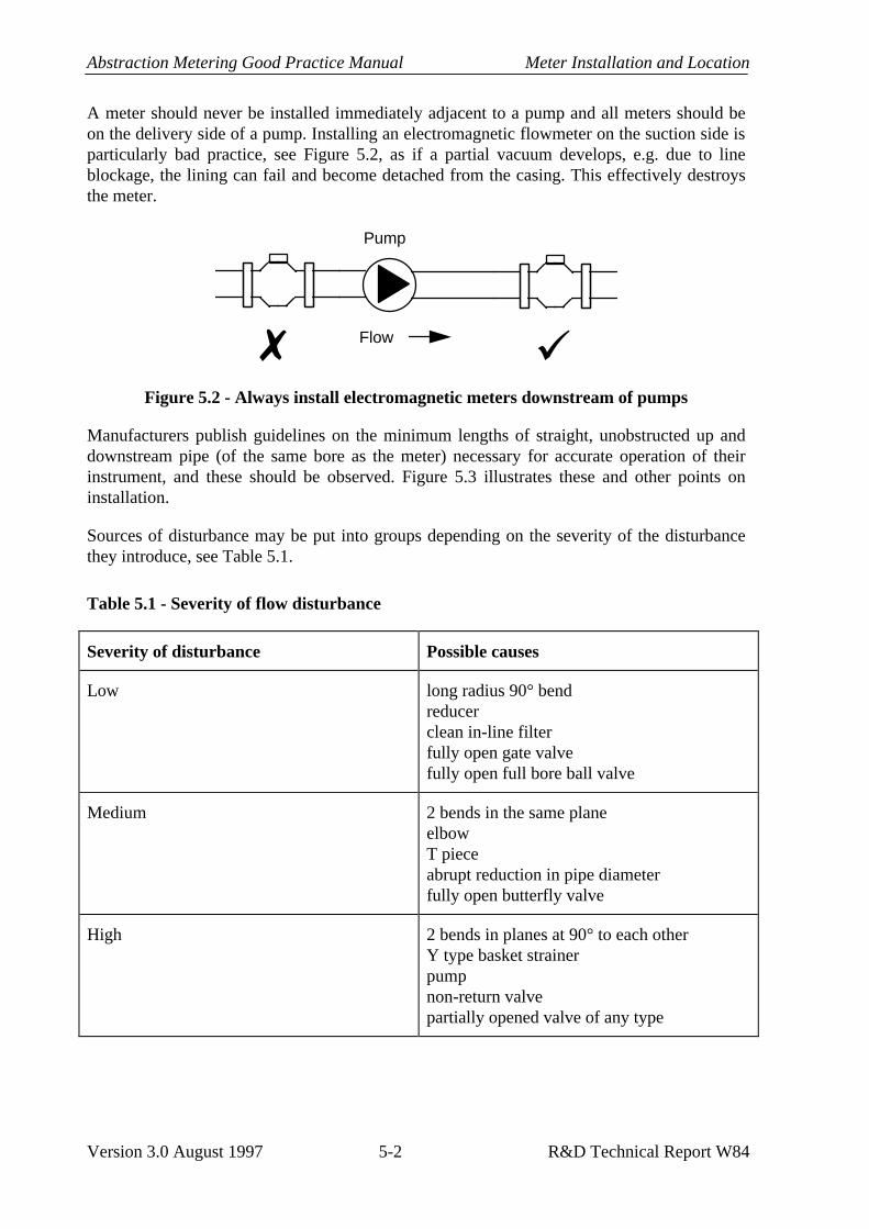
Abstraction Metering Good Practice Manual Meter Installation and Location
Version 3.0 August 1997 5-2 R&D Technical Report W84
A meter should never be installed immediately adjacent to a pump and all meters should be on the delivery side of a pump. Installing an electromagnetic flowmeter on the suction side is particularly bad practice, see Figure 5.2, as if a partial vacuum develops, e.g. due to line blockage, the lining can fail and become detached from the casing. This effectively destroys the meter.
Pump
7 üFlow
Figure 5.2 - Always install electromagnetic meters downstream of pumps
Manufacturers publish guidelines on the minimum lengths of straight, unobstructed up and downstream pipe (of the same bore as the meter) necessary for accurate operation of their instrument, and these should be observed. Figure 5.3 illustrates these and other points on installation.
Sources of disturbance may be put into groups depending on the severity of the disturbance they introduce, see Table 5.1.
Table 5.1 - Severity of flow disturbance
Severity of disturbance Possible causes
Low long radius 90° bend reducer clean in-line filter fully open gate valve fully open full bore ball valve
Medium 2 bends in the same plane elbow T piece abrupt reduction in pipe diameter fully open butterfly valve
High 2 bends in planes at 90° to each other Y type basket strainer pump non-return valve partially opened valve of any type

Meter Installation and Location Abstraction Metering Good Practice Manual
R&D Technical Report W84 5-3 Version 3.0 August 1997
Test results have been published by a number of organisations, including WRc and NEL, on the performance of meters under disturbed flow conditions which show that the effect of a disturbance on performance varies considerably from meter to meter, even within a batch of meters using the same operating principle.
However, the guidelines in Table 5.2 have been compiled from a number of sources and should be considered good practice. The lengths should be made up of straight rigid pipe. As the size of the installation becomes larger, it becomes increasingly difficult to achieve these distances. In such cases the abstractor should be able to demonstrate by an in-situ verification that the meter is within the required performance specification.
It is very difficult to predict the behaviour of a meter in conditions outside those recommended by the manufacturer, other than to say the accuracy will probably be impaired. An in-situ flow check would be needed to quantify the effect.
Table 5.2 - Distances of flowmeter from sources of disturbance
Severity of disturbance
Low Medium High
Meter type Upstream D
Down-stream D
Upstream D
Down-stream D
Upstream D
Down-stream D
Orifice/nozzle (1) 6 5 10 5 18 5
Venturi 0.5 4 0.5 4 10 4
Positive displacement 0 0 0 0 0 0
Turbine 5 3 10 5 20 5
Electromagnetic 5 2 5 2 15 5
Single path ultrasonic 5 2 10 5 40 5
Insertion 10 5 20 5 50 5
Note:
1. Typical figures are given, the exact distance depends on the ratio of the orifice to the full bore (β ratio), see BS 1042 Part 1.

Abstraction Metering Good Practice Manual Meter Installation and Location
Version 3.0 August 1997 5-4 R&D Technical Report W84
Pump
Meter too close to pump
Meter oversized Downstream valve too close to meter
ReducerPipe below meter - metermay not run full
Suctionpipe
7
>10D up and >5D downstream straight pipe
Suctionpipe
Reducer
Riser to keepfull pipe
Delivery
Expander
Pump
Isolation valves
Drain
ü
Figure 5.3 - Bad and good installation practice
5.1.3 Flow straighteners
Flow straighteners or conditioners will not often be found in abstraction measurement
A flow straightener is a device which may be inserted into the pipe to remove any distortions in the velocity profile and help to recover a fully developed profile in a much shorter distance than would be taken without the straightener. Several designs are available, for example tube bundle, étoile (vaned) or perforated plate, see Figure 5.4. A short distance, typically 3D for an étoile, 5D for a tube bundle and 10D for a perforated plate, is required between the outlet of a straightener and the inlet of the meter. Certain meter manufacturers also produce proprietary straighteners for use with their, or other manufacturers’, meters.
Many more sophisticated designs are available, often based on a combination of these three basic types, but these tend to be specialist tools found where high accuracy is essential, e.g. certain industrial processes.
All straighteners will introduce a head loss though this is low for tube bundle and étoile types. All designs are prone to blockage if weeds, etc. are present in the flow. Whilst flow

Meter Installation and Location Abstraction Metering Good Practice Manual
R&D Technical Report W84 5-5 Version 3.0 August 1997
straighteners are useful in some restricted situations, it is usually preferable to engineer the installation with the recommended up and downstream pipe lengths, see Table 5.2.
Étoilelength 3-5D
Tube bundlelength 2-3D
Perforated platethickness ≈20mm
Figure 5.4 - Designs of flow straightener
5.1.4 Orientation
The manufacturer’s specification sheet will usually indicate whether the meter can be installed in vertical, horizontal or sloping pipelines. Some types of meter will not function well in vertical pipelines, particularly certain mechanical models where vertical installation will affect the loading on the bearings and lead to increased wear and poor performance. Most non-mechanical meters will function well in vertical installations, see Figure 5.5.
In vertical pipes, it is preferable for the flow tobe upwards to minimise the effect of any gas orair bubbles in the water.
ü
Figure 5.5 - Vertical installation
In horizontal pipelines, electromagnetic and ultrasonic meters should be installed such that a line drawn between the electrodes or ultrasonic transducers is parallel to the ground, see Figure 5.6. This avoids poor measurements due to air gaps which may be at the top of the pipe or silting at the bottom.

Abstraction Metering Good Practice Manual Meter Installation and Location
Version 3.0 August 1997 5-6 R&D Technical Report W84
Figure 5.6 - Installation of electromagnetic and ultrasonic instruments
5.1.5 Full pipe
Except for a few particular meters which are specifically designed to be used in part-filled pipes, all meters for closed pipe applications require the pipe to be running full for correct operation. It may be necessary to introduce a local kink or shallow U section in the pipe to achieve this, see Figure 5.7. Particular situations to avoid are at a high point where air will accumulate and on downward or horizontal pipes which are open at the end, see Figure 5.8.
The effect of having a partially filled pipe varies from meter to meter and with the amount of water present in the pipe. Some will fail to register and others will substantially over record.
Water Air
ü
Figure 5.7 - Installing the meter to maintain a full pipe

Meter Installation and Location Abstraction Metering Good Practice Manual
R&D Technical Report W84 5-7 Version 3.0 August 1997
Source Pump
A B
C
D
Open delivery
Minimum dimensions of A, B, C and D as given in Table 5.2.
Figure 5.8 - Suitable and unsuitable meter locations
5.1.6 Provision for flow checking
Provision needs to be made in the installation for the in situ flow checking of the meter. This will require straight lengths of pipe up or downstream of the meter in accordance with the recommendations in Table 5.2. T pieces, valves or tappings, may also be needed depending on the method of checking to be used, see Section 6.2.
5.1.7 Meter isolation
Isolation valves may be fitted up and downstream of a meter (preferably 10D and 5D respectively from the meter) with a drain cock between the meter and the downstream valve, to enable it to be isolated for repair or removal.
5.2 Flow conditions
5.2.1 Flow direction
Most flowmeters will be marked with an arrow indicating the preferred direction of flow. For meters capable of measuring bi-directional flow (i.e. flow in either direction through the meter) this will be the direction of positive flow. Some meters will be damaged by reverse flow and if this is likely to occur, e.g. where water may siphon back through a stopped pump, a non-return or check valve should be fitted. Again manufacturer’s data should indicate whether a particular meter is capable of measuring flow in both directions.
5.2.2 Pulsating flow
Pulsating flows such as those arising from the use of reciprocating pumps, oscillating valves or regulators will cause the majority of flowmeters to over register. Pulsation dampers are

Abstraction Metering Good Practice Manual Meter Installation and Location
Version 3.0 August 1997 5-8 R&D Technical Report W84
available to minimise the problem but these can introduce significant pressure drops and add to the expense and complexity of an installation.
5.2.3 Available head
Some abstractions rely on low head sources, usually gravity fed. Meters used in such circumstances should have a low head loss themselves. Cavitation can occur in mechanical meters where the upstream head is too low, causing damage to the meter and poor readings.
5.3 Location
5.3.1 Security
The meter should be installed as close to the source as possible (subject to the considerations in Section 5.1.1). This is minimise the loss of water through unmetered leakage and the possibility of the meter being by-passed.
Where possible, the meter and surrounding pipework should be clearly visible to assist inspection. Where the installation is open to public access this may not be appropriate due to the possibility of vandalism or other unauthorised tampering.
Vandalism on remote sites can be a serious problem. This may be to the meters themselves, pipework or other fittings. Simple precautions against this include making the pipework and meter as unobtrusive and unattractive as possible. Where persistent vandalism occurs, equipment may need to be installed in secure buildings or underground chambers.
5.3.2 Power supply
The availability, or lack, of a local power supply may limit meter choice. Mechanical meters do not require any electrical power supply, drawing the energy needed to drive the meter from the flow itself. However power may be needed if an electrical pulse unit is attached to such a device for automatic reading.
All electronic instruments require a power supply though this may be provided by a battery in some instances. Housings which incorporate solar panels to maintain battery charge are available for use in remote locations.
5.3.3 Ambient conditions
The majority of instruments likely to be used for abstraction metering will not be affected by the normal variations in atmospheric pressure, temperature and humidity. However the following points should be considered:
• Condensation in the register of a mechanical meter is sometimes a problem which makes reading difficult, but many meters include an integral wiper to overcome this. Avoiding opening the cover in very cold conditions or direct sunlight can reduce the problem;

Meter Installation and Location Abstraction Metering Good Practice Manual
R&D Technical Report W84 5-9 Version 3.0 August 1997
• Meters should be protected from frost and freezing during periods of low temperature as this is likely to cause damage. Protection may be provided by:
− removing and storing the meter (see Section 3.5.4) when not in use, − installing the meter in a housing with background heating, − lagging, − trace heating;
• Electronic equipment generally should not be installed in positions where it is likely to be in direct sunlight for long periods, see Figure 5.9. The temperature inside a sealed box in such circumstances can rise far higher than the ambient air temperature and impair the operation of the electronic circuitry;
Avoid siting in direct sunlight. If a sheltered spot is not readily available a shieldshould be provided.
ü 7
Figure 5.9 - Avoid installation in direct sunlight
• Installation in areas where corrosive atmospheres or where the meter may be standing in corrosive liquids should be avoided, Figure 5.10. Corrosion will attack vulnerable parts like electronic connectors, plugs and cables first and is likely to cause a gradual deterioration in performance before total failure;
7
Figure 5.10 - Avoid sites where chemical leaks or spillage may occur

Abstraction Metering Good Practice Manual Meter Installation and Location
Version 3.0 August 1997 5-10 R&D Technical Report W84
• IP ratings are used in industry to describe the protection an enclosure has against solid objects and ingress of water. Meters should have the appropriate environmental protection (IP rating) for the conditions where they are installed. IP ratings are defined in the International Standard IEC 529 and summarised in Table 5.3. For equipment installed outdoors, it is likely that a rating of at least IP 65 will be needed, IP 68 in installations where the meter may become submerged. For meters installed indoors or in secondary enclosures, a lesser rating may be sufficient;
• Avoid positions where there is vibration in the pipe. This can cause particular problems with ultrasonic flowmeters, leading to poor measurement. With other types of meter, rubber couplings either side of the meter, at least 5D upstream and 2D downstream, can be used to minimise the effect on the meter, as can be seen in Plate 5 Appendix C;
7
Figure 5.11 - Avoid positions where vibration may be present
• The meter should be supported on either side, particularly if plastic pipe is being used, to minimise stresses on the pipe and the likelihood of failure, Figure 5.12; and
ü
Figure 5.12 - Meter should be supported
• Some sensors may be buried, however this practice is not recommended for abstraction meters as it makes examination of the meter and flow checking very difficult. If the meter is installed below the level of the ground, it should be in a brick walled chamber with adequate access for reading and inspection.

Meter Installation and Location Abstraction Metering Good Practice Manual
R&D Technical Report W84 5-11 Version 3.0 August 1997
Table 5.3 - Summary of IP ratings from IEC 529
The first numeral indicates the degree of protection against solid objects
First numeral Description
0 Not protected
1 Protected against solid foreign objects of 50mm diameter and greater
2 Protected against solid foreign objects of 12.5 mm diameter and greater
3 Protected against solid foreign objects of 2.5 mm diameter and greater
4 Protected against solid foreign objects of 1.0 mm diameter and greater
5 Dust shall not penetrate in a quantity to interfere with satisfactory operation of the apparatus or to impair safety
6 Dust tight
The second numeral indicates the degree of protection against water
First numeral Description
0 Not protected
1 Protected against vertically falling water drops
2 Protected against vertically falling water drops when enclosure tilted up to 15°
3 Protected against spraying water
4 Protected against splashing water
5 Protected against water jets
6 Protected against powerful water jets
7 Protected against the effects of temporary immersion in water
8 Protected against the effects of continuous immersion in water at a specified depth

Abstraction Metering Good Practice Manual Meter Installation and Location
Version 3.0 August 1997 5-12 R&D Technical Report W84
5.3.4 Electrical interference
Overhead power cables, generators, motors or high voltage switch gear may all produce electromagnetic interference (EMI) and/or radio frequency interference (RFI). This may have an adverse affect on any electronic parts of a meter either interfering with the measurement itself or the subsequent processing and transmission of the data. Cables should be routed well away from potential sources of interference and electrically screened to minimise such problems. Recent European legislation6 means that modern instruments, designed since 1987 say, should not be seriously affected by such interference but with old instruments it was a common problem.
5.3.5 Strainers
Many types of flowmeter, particularly mechanical types, will be damaged or have their measurement seriously impaired by weeds, gravel and other matter which may be found in raw water.
To minimise this problem, one or more of the following methods should be used:
• a screen, basket or rosette fitted to the pipe at the intake to minimise any incursion by large pieces of debris;
• supporting the intake on floats to prevent gravel, etc. being sucked from the bed of the source; or
• fitting an in-line strainer.
The choice of method will depend on local site conditions, such as the nature of the debris, size of abstraction and the equipment which needs protection. There are several implications to fitting a strainer which should be borne in mind which are as follows:
• Head loss - Strainers will introduce a permanent head loss, particularly as they fill or become blocked, which will reduce the flow;
• Flow disturbance - Some types of strainer, e.g. Y type basket strainers, will distort the velocity profile and hence it is necessary to ensure that there is sufficient length of pipe between the strainer and the meter, see Section 5.1.2; and
• Maintenance - Strainers will require emptying and cleaning on a regular basis. Chemically aggressive waters can corrode filters.
Some mechanical meters which have been specifically designed for raw water, particularly for irrigation use, have built in strainers.
If the source always contains large amounts of solid material and debris, then the frequent emptying of a strainer or basket may make mechanical meters uneconomic and a non-intrusive device, e.g. a full bore electromagnetic or ultrasonic meter, will be preferable despite the higher initial purchase price.

Meter Installation and Location Abstraction Metering Good Practice Manual
R&D Technical Report W84 5-13 Version 3.0 August 1997
5.3.6 Safety
Safety is of critical importance in all installations. Safe access to the meter will be required for reading, maintenance and inspection. There are a number of potential hazards which may be found when installing, inspecting, reading or maintaining a meter which include:
• working with electricity;
• working near water;
• lone working;
• confined spaces;
• lifting heavy objects, e.g. drain covers;
• pipelines under pressure; and
• chemicals (e.g. tracers or cleaning/disinfection agents).
The Health and Safety note at the beginning of this manual gives references to the Agency’s procedures but those of the abstractor should also be consulted and, in cases of difference, the more stringent code applied.
Extra safety precautions may be needed on remote sites to which the public may have access.

Abstraction Metering Good Practice Manual Meter Installation and Location
Version 3.0 August 1997 5-14 R&D Technical Report W84
This page is left blank intentionally

Flow Checking and Meter Calibration Abstraction Metering Good Practice Manual
R&D Technical Report W84 6-1 Version 3.1 February 2002
6. FLOW CHECKING AND METER CALIBRATION
6.1 Introduction
Most flowmeters will have been calibrated before delivery by the manufacturer. This is to ensure that they are within specification. Electronic meters generally come with a calibration certificate showing the results from the calibration of that particular meter. Other meters, e.g. turbine types, do not come with calibration data but should have a conformance certificate or statement which says that the meter has been tested and is within specification. Meters which do not come with any such assurance are unlikely to meet the requirements for abstraction metering. Abstractors should retain this information for inspection by the Agency.
The manufacturer’s calibration will have been performed on a test rig under ideal installation conditions. This demonstrates the best performance which will be obtained from that meter. The installed performance is not likely to be as good as this and will depend on local site conditions. The way the meter is installed plays a major role in determining the installed accuracy but water quality and local environmental conditions will also have an effect.
The abstractor should ensure that the performance of the meter is checked at intervals throughout its life as mechanical components will wear and the performance of some electronics components will drift with time.
It is difficult to specify a precise interval at which instruments should be flow checked as wear and drift rates will depend greatly on local conditions. Manufacturers may be able to recommend an appropriate interval, given data on the site conditions. Currently there are no recognised guidelines in the UK for the frequency of flow checking a meter but the intervals in Table 6.2 are suggested. These are based on the type of meter, the use, source quality and licence criticality.
Meter type - Meters have been grouped depending on the effect that different aspects of water quality are likely to have on their performance. Table 6.1 gives a key to the categories adopted when determining intervals for flow checks.
Water quality - The presence of foreign matter in the water will affect the wear on the meter and hence the interval at which it should be checked. Further discussion on water quality can be found in Section 3.3.1. In Table 6.2 clean water refers to water which contains no filamentous material, large pieces of debris, gravel or significant quantities of sand. Small amounts of fine sand or silt are acceptable. If grit and weeds are present, the shorter of the two time intervals which may be derived should be applied. It also assumes an average mineral content and acidity. On sites where the source is particularly acidic or rich in minerals the frequency of flow checking and meter examination may need to be increased.
Duty - Continuous applies where the abstraction is in constant use and the meter is running continuously within its operating range. Intermittent applies to situations where the abstraction is stopping and starting, for instance where a header tank or reservoir is being filled. Seasonal applies to abstractions where the meter will be taken out of service and put in

Abstraction Metering Good Practice Manual Flow Checking and Meter Calibration
Version 3.1 February 2002 6-2 R&D Technical Report W84
store for part of the year, e.g. irrigation. If the abstraction is not used during one particular year then that year need not be counted when determining the interval for flow checking.
Licence criticality - More frequent checking may be required for sources where it is necessary to maintain a tight monitoring regime, e.g. due to environmental significance or size, see Section 3.3.2.
Table 6.1 - Key to meter types in Table 6.2
Meter type Instruments included
A Rotary piston Mechanical turbines (Woltmann, combination, jet and irrigation meters) Orifice plates
B Insertion probes (electromagnetic, vortex and differential pressure) Venturi tubes Differential pressure transmitters Vortex meters
C Electromagnetic flowmeters Ultrasonic flowmeters
6.1.1 In situ and laboratory flow checks
Methods for flow checking can be divided into two categories:
• laboratory methods, where the meter is removed from the line and taken to a specialist laboratory with a flow test rig; and
• in situ methods which check the meter while it is in place in the line.
Some techniques are more suited to proving the accuracy of flow rate measurements and some to total volume passed.
In any flow check it is preferable to take a number of points spaced throughout the normal operating range of the instrument.
It is important that abstractors keep records of all flow checks, in situ and laboratory. These should include the date of the test, results and the method used.

Flow Checking and Meter Calibration Abstraction Metering Good Practice Manual
R&D Technical Report W84 6-3 Version 3.1 February 2002
Table 6.2 - Intervals for flow checking (in years of use)
Flow check intervals (years)
Meter type Water quality Duty Licence criticality
Highly critical
Critical Less critical
Continuous 2 3 5 Clean water Intermittent 2 3 5 Seasonal 2 4 6 Continuous 1 2 3
A Water with sand or grit Intermittent 1 2 3 Seasonal 2 3 4 Continuous 1 2 3 Water with weeds Intermittent 1 2 3 Seasonal 2 3 4 Continuous 3 4 5 Clean water Intermittent 3 4 5 Seasonal 3 4 5 Continuous 3 4 5
B Water with sand or grit Intermittent 2 3 4 Seasonal 2 3 4 Continuous 2 3 4 Water with weeds Intermittent 2 3 4 Seasonal 3 4 5 Continuous 3 5 7 Clean water Intermittent 3 5 7 Seasonal 3 5 7 Continuous 3 5 7
C Water with sand or grit Intermittent 3 5 7 Seasonal 3 5 7 Continuous 3 5 7 Water with weeds Intermittent 3 5 7 Seasonal 3 5 7
6.1.2 Traceability
If the flow check is to be credible, it must be traceable back to National Standards. This means that the components of the method used to check the meter should themselves have been calibrated against a standard of higher accuracy and so on until the National Standard is reached for each component.

Abstraction Metering Good Practice Manual Flow Checking and Meter Calibration
Version 3.1 February 2002 6-4 R&D Technical Report W84
This is not usually a problem with laboratory based methods, but establishing the traceability of an in situ method may be very difficult and in many cases practically impossible.
Some laboratories are UKAS accredited. UKAS is the United Kingdom Accreditation Service of which NAMAS is a part. This means that their procedures for ensuring the traceability of their test methods have been assessed and approved by an independent body. A directory of accredited laboratories is available from UKAS.
6.1.3 Accuracy of flow checking
It is preferable that the method being used to flow check a meter is more accurate than, or at least as accurate as, the meter being tested, for example a transfer standard.
However, for in situ flow checks it is often the case that the method being used is potentially less accurate than the meter it is being used to check, e.g. a clamp-on ultrasonic having an uncertainty of ±5% being used to check a turbine meter with an uncertainty of ±2%. This will only detect any large errors present and errors less than the uncertainty of the reference method may not be picked up.
Before a reference method or instrument is used in the field it will be necessary to establish its performance characteristics, i.e. its bias and standard deviation. These may be obtained from laboratory tests on the equipment to be used.
For all in situ flow checks, a number of pairs of readings should be recorded, each pair comprising a reading from the meter and a reading from the reference method taken simultaneously. For good practice some 20 to 30 pairs are needed. This will often be impractical but at least six pairs should always be taken. The difference between each pair should be calculated and the mean of the differences found. This can be expressed as a percentage of the “true” flow as given by the reference method.
For practical purposes the following rules of thumb may be adopted, (note these are based on experience rather than strict statistical rules).
• If the mean difference is less than or equal to the reference method accuracy, the meter is probably within specification;
• If the mean difference is greater than or equal to twice the reference method accuracy, the meter is probably outside specification and requires further investigation; and
• If the mean difference lies between these values, and the method has been applied correctly, then investigation by a more accurate reference method, possibly testing at a laboratory, is needed.
See Table 6.5 for an example using a clamp-on ultrasonic flowmeter.

Flow Checking and Meter Calibration Abstraction Metering Good Practice Manual
R&D Technical Report W84 6-5 Version 3.1 February 2002
6.2 In situ methods
The advantages of in situ flow checks are:
• minimal disruption to the abstraction;
• installation conditions are taken into account; and
• checks can be undertaken over a longer period of time which may give a more representative result.
The disadvantages are:
• some techniques are inherently less accurate than the meter being checked;
• they will not give the same level as accuracy as a laboratory test;
• it may be difficult to demonstrate traceability; and
• stable flow conditions are needed while the flow check is being performed.
The techniques for in situ flow checks are described below but the choice of method depends on the local site conditions. In order of preference, these may be listed as follows:
1. reference meter (transfer standard) (see Section 6.2.1)
2. volumetric methods (see Section 6.2.2)
3. clamp-on or insertion meters (see Sections 6.2.3 and 6.2.4)
4. thermodynamic and tracer methods (see Sections 6.2.5 and 6.2.6).
Those mentioned under 4 are the most complicated techniques and require sophisticated equipment, hence they will usually need to be performed by specialist contractors. Compact provers will also not be generally applicable to abstraction meter checking. Contractors offering in situ flow checks are listed in Appendix D.
Before any checks are performed, the following points should be observed:
• the system should be checked for leakage, and any leaks plugged;
• any instrument settings or programming should be inspected to ensure that they are correct;
• for differential pressure devices check tappings and lines are clear; and
• a zero test should be performed on electronic meters, i.e. stop the flow totally, without draining the system, and the flow rate reading should go to zero. Check the valves have

Abstraction Metering Good Practice Manual Flow Checking and Meter Calibration
Version 3.1 February 2002 6-6 R&D Technical Report W84
fully seated and that there really is zero flow before adjusting, i.e. allow time for the water to settle. (Zero drift is a common problem on old electromagnetic flowmeters and the zero can usually be adjusted by a potentiometer within the electronics, using guidance from the manufacturer’s instructions.)
6.2.1 Reference meter (transfer standard)
In this method a second meter, of known performance is placed in series with the meter to be tested. There are several ways of achieving this, but it is important to ensure that good installation conditions for the reference meter are provided and that the meters do not interfere with one another, see Figure 6.1. Where the transfer standard is installed in a by-pass or in a separate leg, the second and third illustrations, the connecting pipes may be flexible but they should be kept as short as possible and the pipework attached directly to the reference meter must be rigid. The transfer standard meter must also be of a type appropriate to the water quality and site conditions. A means of showing that there is no leakage past the valves isolating the main pipe (those marked with a ∗ in Figure 6.1) is also useful. This may be done by using double block and bleed type valves.
Advantages include:
• accuracy better than (or at least as good as) the meter under test;
• method can be made traceable by using a meter, preferably with its own dedicated sections of up and downstream pipework, that has been traceably calibrated at a laboratory;
• any fluctuations in flow will be seen by both meters; and
• this method may be used for either flow rate or total volume passed tests.
Disadvantages include:
• there will usually be some disruption to the supply of abstracted water unless the facility for doing the tests has been engineered into the installation;
• application may be difficult with large meters, > 300mm;
• there may not be a pipe length near the meter of sufficient length in which to fit the transfer standard; and
• the user would need to have a large number of similarly sized meters to make keeping a transfer standard economical.
Clamp-on and insertion meters cannot be regarded as transfer standards, unless they can be installed in a repeatable fashion on a length of pipe in which they have been calibrated.

Flow Checking and Meter Calibration Abstraction Metering Good Practice Manual
R&D Technical Report W84 6-7 Version 3.1 February 2002
A
A
B
B
C
C
Flanged section in main line toaccommodate transfer standard
Flanged section in by-pass leg
R
R
*
Supply
Waste
A
B
C
Transfer standard in separate line
R
Distances A, B and C from Section 5.1
R
*
*
Pump
Valve
Duty meter
Transfer standard meter
Double block and bleed type
Figure 6.1 - Examples of how to include a transfer standard

Abstraction Metering Good Practice Manual Flow Checking and Meter Calibration
Version 3.1 February 2002 6-8 R&D Technical Report W84
6.2.2 Volumetric methods and drop tests
The volumetric method is straightforward in concept though often difficult to engineer in the field, except for small size meters. Water passed through the meter is diverted into a tank or reservoir of known volume. The quantity collected can be compared to that recorded by the meter.
Drop tests are a similar idea, though in this case the water is collected and then passed through the meter, see Figure 6.2. This technique may be possible where water is abstracted and stored in a reservoir or large constant head tank prior to use. To perform the check, the supply to the reservoir is cut off and the water stored allowed to flow out and through the meter. The quantity passed can be calculated by the drop in level and the cross sectional area of the reservoir and compared to the meter reading.
This method is used to determine the total volume passed through any size of pipe. It is particularly useful on small sizes of pipe, e.g. domestic or agricultural abstractions with a ½” to 1½” (15 to 40mm) line, where the volume collected may be relatively small.
Accuracy can be high, 1% or better where the dimensions of the reservoir can be precisely established, but this becomes less easy as the size of the reservoir needed increases or on site, rather than mobile, facilities are used. In the latter cases, an accuracy of 5% is more likely.
Insertion meter to monitor flow rate
(optional)
Meter under test
hReservoir cross section A m2
Total volume through meter = Ah m3
Average rate of flow through meter = Ah/t m3/s
where t is the time taken in seconds for the surface to drop distance h metres
Figure 6.2 - Reservoir drop test

Flow Checking and Meter Calibration Abstraction Metering Good Practice Manual
R&D Technical Report W84 6-9 Version 3.1 February 2002
Problems include:
• on large abstractions, having a sufficiently large volume into which the flow can be diverted, or drawn from, to obtain a representative reading;
• supply from the abstraction will be interrupted whilst the test is performed; and
• establishing traceability. For a mobile facility it is straightforward to calibrate the reservoir being used but it is more difficult when using existing on site facilities as another link in the chain of traceability is needed to establish the precise dimensions of the facility.
6.2.3 Insertion meter
Insertion meters are discussed above in Section 4.9 and similar caveats apply to their use for testing as for permanent installations. To use an insertion meter for flow checking it is necessary to have an appropriate tapping in the meter line. This should be sufficiently far from any fittings to ensure good flow conditions, see Section 5.1, and from the meter under test to ensure that they do not interfere with one another; recommended distances are listed in Table 6.3.
Table 6.3 - Distances from meter when using an insertion probe
Type of meter under test Minimum distance between test meter and downstream insertion probe
Woltmann, jet 20D
Insertion, positive displacement, orifice, nozzle, Venturi
10D
Full bore electromagnetic, ultrasonic 5D
Traverses across the pipe should be performed on at least one diameter, and preferably also on a second diameter at right angles to the first, to establish the velocity profile. A stable flow is necessary when traverses are being performed as the velocity profile changes with flow rate. The velocities across the profile can be integrated to give the total flow. Once a profile has been established, and as long as the flow rate remains constant, the probe may be left at a certain position, e.g. at the point of mean flow. Figure 6.3 illustrates this method.

Abstraction Metering Good Practice Manual Flow Checking and Meter Calibration
Version 3.1 February 2002 6-10 R&D Technical Report W84
Measurement point
1st diameter
2nd diameter
An
Cross section at insertion meter location
Insertion meterMeter under test
Total flow rate (Q) through themeter equals the sum of the averagevelocity for each annulus (Vn)multiplied by the cross sectionalarea of that annulus (An).
i.e. Q = ΣAnVn
Figure 6.3 - Testing with an insertion meter
BS 1042 Part 2 gives further guidance on the use of velocity area methods in closed pipes.
This technique is best suited to larger pipes, > 200mm. On smaller pipes the effects of the blockage due to the presence of the probe become very significant.
This method may be used for rate or total volume passed tests. Traceability of the probe velocity measurement in a certain pipe or tow tank is possible, but it is difficult to make the volumetric measurement required in the field traceable. Accuracy is likely to be 5% at best.
6.2.4 Clamp-on meter
There are several portable clamp-on ultrasonic flowmeters available for site survey work which offer a quick and reasonably straightforward means to flow check a meter. Plate 6 Appendix C shows a portable clamp-on meter in use. The use of such devices has been discussed above in Section 4.8 and similar considerations apply to their use as meter testing tools as for permanent installations:
• The instrument must be programmed with the correct data, for example on internal pipe dimensions and materials;
• A fully developed velocity profile is needed for good results, i.e. the distances given in Section 5.1.2 should be observed;

Flow Checking and Meter Calibration Abstraction Metering Good Practice Manual
R&D Technical Report W84 6-11 Version 3.1 February 2002
• The pipe must be running full;
• If the clamp-on is being used downstream of the meter under test, the distances in Table 6.4 should also be observed to minimise any flow disturbance caused by the meter;
• Good acoustic coupling is needed between the pipe wall and the transducer. This is achieved by cleaning the pipe and using a coupling gel; and
• Doppler types require some particulate matter or gas to be entrained in the flow for their operation. Transit time devices can cope with moderate amounts of material in the flow.
Table 6.4 - Distances from meter for using a clamp-on
Type of meter under test Minimum distance between test meter and downstream clamp-on
Helix, jet, combination, positive displacement
40D
Insertion, vortex, orifice, nozzle, Venturi
10D
Full bore electromagnetic, ultrasonic
5D
As a clamp-on device does not itself introduce any flow disturbance it may be installed upstream of the meter to be tested, allowing 5D between it and the meter, provided there is sufficient distance between it and any disturbance further upstream.
The main impairment to the measurement being made traceable is the difficulty in establishing precise data on the pipe, particularly those aspects which may not be obvious from the outside, e.g. internal diameter, wall thickness.
This method may be used for flow rate or total volume passed tests. Clamp-on meters may be used on pipes from 15mm to 2m and over in diameter.
The accuracy of the method very much depends on local site conditions. With good, clean pipe of known dimensions, away from sources of flow disturbance, an accuracy of better than 5% may be obtained. However, as the conditions become less good, i.e. the dimensions of the pipe are less precisely known or there are sources of flow disturbance nearby, the accuracy deteriorates. For example, good results can be obtained for many spray irrigation applications where there are long lengths of regular aluminium pipework on which to clamp the meter. On old cast iron pipes, which may have considerable internal corrosion, clamp-on meters will not give good results.

Abstraction Metering Good Practice Manual Flow Checking and Meter Calibration
Version 3.1 February 2002 6-12 R&D Technical Report W84
Many modern instruments include an indication of the strength or the quality of the received signal which can be a useful guide on the quality of the results. Low strength or noisy received signals will not tend to yield reliable results.
The rules of thumb described above in Section 6.1.3 may be applied to flow checks with clamp-on meters as shown in Table 6.5.
Table 6.5 - Flow checking with a clamp-on ultrasonic flowmeter
Mean difference Result and possible courses of action
≤5 % Meter under test probably within specification No action needed
5% < difference < 10% Check set up of clamp-on, transducer installation and programmed data, and repeat test If possible use another method to corroborate the results or a “better” site for the clamp-on Is the installation of the meter satisfactory, if not suggest improvement, e.g. resiting, and check again when done Is there anything visibly wrong with the meter, e.g. jerky register, physical damage, which may indicate failure? If so meter should be repaired or replaced If the meter appears sound, is installed correctly and there is no possibility of using another in situ method, the meter will have to be tested at a laboratory.
≥ 10% Probably a fault with the meter under test, check set up of clamp on first and repeat test to confirm Severe flow disturbance*, e.g. a pump very close by, could cause errors of this magnitude, particularly at low flows. If installation is very poor and meter appears sound, suggest resiting, and check again when done Otherwise, meter should be repaired or replaced.
* Those listed under “High” in Table 5.1.
6.2.5 Thermodynamic method
As mentioned in Section 4.11, it is possible to infer the flow rate from measurements of the temperature and pressure differences across a pump and the power supplied. Pump efficiency curves are also needed in some cases. To use this method a lift of at least 25m is needed. This is a technique requiring specialist equipment and expertise and will only be applicable to a limited number of sites. The number of variables involved, including the installation of the
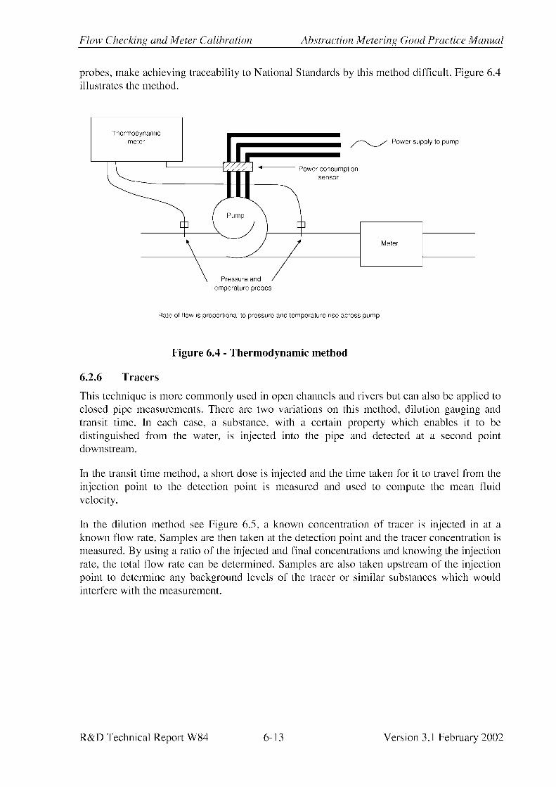


Flow Checking and Meter Calibration Abstraction Metering Good Practice Manual
R&D Technical Report W84 6-15 Version 3.1 February 2002
• the number of variables involved, including the sampling locations and procedures, make achieving traceability by this method difficult.
This technique determines flow rate and cannot be used for total volume passed. Accuracy at best is likely to be 3%, but is more likely to be worse than 5%.
6.2.7 Compact prover
Provers are most often used in the oil and chemical industries. They are smaller versions of the prover loop described below (Section 6.3). The compact prover is often mounted on a trailer. Even though it measures the time taken to pass a known volume, the volumes and times involved are so low that it is really a test for flow rate measurement. This method is highly accurate, better than 1%, and traceable. Typically, meters up to 100mm may be tested by this method. The main barrier to its use for abstraction meters is the lack of availability of appropriate equipment.
6.3 Laboratory methods
The advantages of laboratory based flow checks are:
• good traceability;
• enable meter to be tested over its full range;
• generally more accurate than in situ checks; and
• provide data that is comparable with the original manufacturer’s calibration.
The disadvantages are:
• likely to be more expensive than an in situ flow check;
• cost of removing, transporting and reinstalling meter;
• takes no account of the installation conditions;
• the disturbance caused by removal of the meter may change its characteristics, for example a piece of debris which had been trapped in the meter causing it to read incorrectly may become dislodged so that when the meter is tested, it will work correctly; and
• disruption to the supply on continuous abstractions.
There are a number of organisations which have facilities for meter calibration and flow checking. These are listed in Appendix D.
The meter is installed on a purpose built rig where flow rates and fluid conditions can be closely monitored and controlled. A quantity of water will be passed through the meter and measured by one of several methods. These include:
• weigh tank (collection of a known mass of water in a measured time);
• volumetric flask (collection of a known volume of water in a measured time);

Abstraction Metering Good Practice Manual Flow Checking and Meter Calibration
Version 3.1 February 2002 6-16 R&D Technical Report W84
• calibrated high accuracy reference meter, also known as a transfer standard (usually a positive displacement, high accuracy turbine or electromagnetic type);
• prover loop (this comprises a section of pipe of known volume in which a tightly fitting sphere or piston is mounted; the flow pushes the sphere or piston through the pipe and its time of travel between two set points at the inlet and outlet of the known volume section is measured.); and
• tow tank tests for insertion probes (the probe is towed along immersed in a tank of water at a known velocity).
Results may be expressed in a number of ways:
• as flow rate measurements;
• in terms of total volume passed; or
• for electronic outputs, as a meter factor, i.e. the average number of pulses per unit volume passed. These must be compared with the factor set in the counter to determine error.
Pressure instrumentation may also be calibrated in a laboratory, either by dead weight testers or against a pre-calibrated reference gauge.
6.4 Electromagnetic meter verification tools
Important Note: The use of an electronic verification tool by itself does not demonstrate the accuracy of the flow measurement. Certificates from such tools should not be accepted without accompanying data from a flow check carried out by a method which directly measures the flow, such as those described in preceding sections.
A number of the manufacturers of electromagnetic flowmeters offer electronic tools which can verify the operation of their own models of flowmeter. At the time of writing (2002) this technology is still developing and research into its capabilities and limitations is on-going. Two systems are in use (the ABB CalMaster and the Danfoss Verificator), though other manufacturers are also developing their own systems. Each manufacturer’s tool comprises an electronic unit which connects into the flowmeter via the meter transmitter. Each tool works in a slightly different way but they all run a series of electronic tests on different aspects of the flowmeter, including the integrity of the sensor, the transmitter and the connecting cables. They check that all the important components of the meter are still functioning as they should. The results are stored and, when the tool is connected to a computer with the appropriate software (each manufacturer provides bespoke packages for their tool), a certificate showing the results of the test is produced. If all the results are within pre-set limits, the meter will be passed. However, if any of the test results have moved outside those limits then the meter will be failed. As with all other verification techniques, it is important that any individual using a verification tool shall have been trained and is competent in its use.
The results from verification tests can also be compared with the results from previous tests on the meter and, if available, a set of equivalent results from the meter at the time of

Flow Checking and Meter Calibration Abstraction Metering Good Practice Manual
R&D Technical Report W84 6-17 Version 3.1 February 2002
manufacture (known as the “fingerprint”). This enables trends to be observed and an early diagnosis of problems before failure occurs.
It is important to remember that such tools:
• do NOT make an independent measurement of the actual flow through the flowmeter and hence cannot be used to calibrate flowmeters;
• will not detect flow measurement errors due to flow disturbance effects or incorrect meter set up (e.g. outputs incorrectly ranged);
• may not detect all faults, particularly intermittent faults;
• do not check the onward measurement chain from the meter, i.e. any telemetry, SCADA or other system from which reported abstraction figures may be taken.
However, they do provide a quick, convenient and reasonably reliable means of checking that a meter is still working. Hence there is growing use of them by water companies for checking abstraction and other meters, particularly where the meter sensor is buried or otherwise difficult to access.
The certificate from a verification tool does not, by itself, prove the accuracy of the flow measurement being made by that meter. There should also be evidence that the installation of the meter is satisfactory and the meter has been correctly programmed, this is particularly important for buried meters, see Section 6.5. Where abstractors are using electronic verification tools in conjunction with flow checks, it may be acceptable to reduce the frequency of formal flow checks provided that the meter continues to pass the electronic verification tests.
Another important point to note is that as these tools run through their test procedures, they exercise the meter outputs over their range and hence will increase the total recorded flow shown on any connected totaliser and the meter display itself. This increase will not correspond to the volume of water passed through the meter during the test. With at least one manufacturer’s equipment, it is possible to reset the totaliser to the value prior to the test using another piece of software. With another manufacturer’s product, the before and after totals are shown on the certificate.
Meter verification tools are distinct from the flow simulators which many manufacturers offer. Flow simulators also plug into the meter transmitter, often in place of the cables to the flow sensor and provide a simulation of the signal that would be coming from the sensor to the transmitter under pre-set flow conditions. They allow the output from the flowmeter to be set up and telemetry links checked under known, simulated flow-rates. Simulators do not generally carry out any checks on the flowmeter.

Abstraction Metering Good Practice Manual Flow Checking and Meter Calibration
Version 3.1 February 2002 6-18 R&D Technical Report W84
6.5 Buried meters
Whilst the burial of meter sensors is not recommended, it is recognised that there may be cases where for economic or practical reasons, it is the preferred option. In situations where the local officer accepts that a meter sensor can be buried, the following good practice should be adopted where practicable.
• The installation of the meter should be audited prior to burial by checking the size and serial number of the meter and that the up and downstream distances comply with the requirements for that meter. In addition, the termination area where the electrical cables from the meter transmitter join into the meter sensor should be potted (filled with an epoxy resin or other sealant), cable glands must be tight and there should be no joins in any buried section of cable.
• Installation drawings should be made available and inspected.
• The set up of the meter transmitter should be verified to ensure that the meter size, flow range etc are correctly set.
• Buried meter sensors should be checked annually using an electronic verification tool (see Section 6.4).
• Where possible flow checks should still be carried out. This may be on an exposed section up or downstream of the meter, though account would need to be taken of any in- or outflows between the point of the flow check and the meter. If such a location is not available, the possibility of cross-referencing readings should be considered, for example comparing abstraction records with works output.
• Records of all checks using verification tools or other methods should be kept and be available for inspection.
6.6 Verification of data transmission and recording
For instruments with an electronic output to an automatic data logging system or remote totaliser, it is also important to verify that the signal reaching the logger or totaliser is correct. There are two approaches to this, either a known signal is imposed onto the transmission line at the meter end and checked on the logger display, an oscilloscope or a multimeter or the signal being generated by the instrument is measured simultaneously at the instrument output and at the logger. Note that some electronic meters incorporate a current or pulse generator which can be set to a known value for this purpose.
Injecting a known signal, calculating the expected reading for that signal and comparing that with what is actually shown is a useful way of detecting errors in the set up of the instrument, for example a wrong span setting or 0-20mA output selected instead of 4-20mA.
Regular comparisons should be made between an instrument’s internal totaliser (where fitted) or the local display and the values recorded on the logger. This should be undertaken at a

Flow Checking and Meter Calibration Abstraction Metering Good Practice Manual
R&D Technical Report W84 6-19 Version 3.1 February 2002
minimum frequency of every 24 months for electromagnetic meters and more frequently for other types. The flowmeter output should be within ±2% of the known input signal.
The equipment used for these tests should be traceably calibrated. This can be done by sending it to a specialist laboratory.
6.7 Remedial action
If the flow check shows that the meter is outside specification, i.e. if at one or more points within its operating range, the error is greater than that permitted, then some remedial action will be necessary. There are two possibilities:
1. The meter is faulty.
2. One or more aspects of the installation or site conditions are causing an error.
It is usually preferable to eliminate the second possibility before condemning the meter and requiring the abstractor to bear the cost of removing and replacing or repairing the meter. The information given in Sections 4, 5 and Appendix B may help. Particular conditions to look for are shown in Table 6.6 with possible courses of action. Site conditions will determine the most appropriate course in each case.
Table 6.6 - Remedial actions
Problem Possible courses of action
pipe not running full resite meter reconfigure pipework (see Section 5.1.5)
meter installed in an unsuitable orientation resite meter reconfigure pipework replace meter
vibration in the pipe secure pipework and meter fit rubber couplings (see Section 5.3.3)
sources of flow disturbance nearby resite meter (see Section 5.1.2) fit flow straightener
radio or electromagnetic interference from nearby cables, e.g. overhead power lines or power lines to pumping equipment.
resite meter screen meter or cables
wrongly sized meter running at the bottom of its range
replace meter (see Section 3.2)
poor coupling for ultrasonic transducers re-install transducers
inadequate earthing on electromagnetic devices re-install all earthing connections

Abstraction Metering Good Practice Manual Flow Checking and Meter Calibration
Version 3.1 February 2002 6-20 R&D Technical Report W84
If such factors have been eliminated or the meter is visibly damaged, e.g. jerky register, severe corrosion or mechanical damage, then the abstractor has the responsibility to have it cleaned, repaired or replaced. This will usually involve removing the meter from the line. This may give a clearer indication of the problem and hence the action needed.
Mechanical meters will usually go out of specification at the low ends of their range first due to wear and require refurbishment. With many smaller sized meters, 100mm or less, replacement will be the most economic course.
Repairs or refurbishment should be carried out by an approved agent, qualified technician or the manufacturer to ensure that the meter performs correctly after repair. A laboratory recalibration may also be necessary.

References and Bibliography Abstraction Metering Good Practice Manual
R&D Technical Report W84 Version 3.0 August 1997
REFERENCES AND BIBLIOGRAPHY
1. Environment Agency Licensing Manual, 020, October 1994.
2. DoE Environmental Statistics No 17 1995.
3. Abstraction Measurement for Incentive Charging - Practical Issues. Final R&D Technical Report W46. January 1997.
4. Annual Abstraction Charges 1995-96.
5. WIS 7-03-01 Process Control and Monitoring Instruments: Specification for Flowmeters. Issue 2 1995. WRc.
6. EMC Directive 89/336/EEC.
OTHER USEFUL TEXTS
Fowles, G. (1993) Flow, Level and Pressure Measurement in the Water Industry. Butterworth Heinemann.
Haywood, AJT. (1979) Flowmeters. Macmillan.
Linford, A. (1961) Flow Measurement and Meters. E & F N Spon.
Miller, RW (1989) Flow Measurement Engineering Handbook, Second Edition. McGraw-Hill.
Spitzer, DW (1991) Flow Measurement. ISA.
BS 7405 (1991) Selection and Application of Flowmeters for the Measurement of Fluid Flow in Closed Conduits. BSi.

Abstraction Metering Good Practice Manual References and Bibliography
Version 3.0 August 1997 R&D Technical Report W84
This page is left blank intentionally

Flow Conversion Tables Abstraction Metering Good Practice Manual
R&D Technical Report W84 A-1 Version 3.0 August 1997
APPENDIX A - FLOW CONVERSION TABLES
1. Volume
1 litre (l) = 0.220 UK gallons
1 megalitre (Ml) = 1 000 000 litres
1 cubic metre (m3) = 1000 litres
1 UK gallon = 4.546 litres
1 US gallon = 3.385 litres
2. Volumetric flow rate
Megalitres per day
(Ml/day)
Cubic metres per hour
(m3/h)
Gallons per minute
(gall/min)
Litres per minute (l/min)
Litres per second
(l/s)
1.0 41.667 152.759 694.444 11.574
0.02400 1.0 3.666 16.667 0.278
0.00655 0.273 1.0 4.546 0.076
0.00144 0.060 0.220 1.0 0.017
0.08640 3.6 13.198 60.0 1.0
3. Pressure
Bar
(bar)
Standard atmosphere
(atm)
Metres head of water
(m H2O)
Feet head of water
(ft H2O)
Pound force per sq. in.
(psi)
1.0 0.987 10.197 33.456 14.504
1.013 1.0 10.332 33.899 14.696
0.098 0.097 1.0 3.281 1.423
0.030 0.030 0.305 1.0 0.434
0.069 0.068 0.703 2.307 1.0

Abstraction Metering Good Practice Manual Flow Conversion Factors
Version 3.0 August 1997 A-2 R&D Technical Report W84
This page is left blank intentionally

Existing Installation Assessment Abstraction Metering Good Practice Manual
R&D Technical Report W84 B-1 Version 3.0 August 1997
APPENDIX B - EXISTING INSTALLATION ASSESSMENT
The following is a checklist of questions which might be asked when assessing a metering installation for compliance with the licence. This is a general list and not all questions will be applicable to all abstractions. References to relevant section numbers in this manual are given in brackets. A form is also included which might be helpful in recording the appropriate details.
The meter:
Meter type/model/serial number. Cross reference serial number and its location with the maintenance and licence records.
Meter installation date/meter age?
Is the meter correctly sized for the flow rates likely to be encountered? (See Section 3.2) Check manufacturer’s specification if available
Is the meter of an appropriate technology for the application? (See Section 4.1)
Does the meter record in metric or Imperial units?
Does it record in appropriately sized units? (See Section 4.12)
Is there any ancillary equipment, e.g. pulse unit, remote totaliser, logger, telemetry link? (See Section 4.12)
General condition of the meter.
Is the dial on the register going around smoothly? Is it jerky or noisy? Unless there is gross damage evident, it is difficult to tell much about the internal condition of a meter from the outside. On mechanical meters, excessive noise or a jerky dial indicates that there may be damage to the internal mechanism of the meter and it is likely to be outside specification.
On mechanical meters, is there any evidence of condensation/leakage in the register? (See Section 5.3.3)
Is there any evidence of tampering, e.g. broken seals?
On mechanical meters, are the counter figures aligned? Misalignment may indicate tampering in a similar way to a car odometer.
Do any parts of the meter look to have been replaced?
What means are in place to protect the meter reading? (See Section 3.4)
Is the meter the normal duty meter for that abstraction or a stand-by? If a stand-by, where is the duty meter?

Abstraction Metering Good Practice Manual Existing Installation Assessment
Version 3.0 August 1997 B-2 R&D Technical Report W84
Meter installation
Is the meter fitted with flow in the direction of the arrow on the meter body? (See Section 5.2.1)
On vertical installations, is the flow upwards through the meter? (See Section 5.1.4)
With electromagnetic meters, are the earthing links attached securely and correctly? (See Section 4.7)
Is the meter protected from frost? (See Section 5.3.3)
Are there sufficient up and downstream straight, unobstructed, rigid pipe lengths between the meter and any fittings? (See Section 5.1.2)
How far is the meter from any pump? (See Section 5.1.2)
Is the meter downstream of the pump? (See Section 5.1.2)
Is the installation such that the meter is kept full of water? (See Section 5.1.5)
Is the meter fitted with a non-return valve or disc type reverse flow restriction device? (See Section 5.2.1)
How is the flow through the meter regulated?
Is the regulation valve downstream of the meter?
Is there any air in the line? (See Section 5.1.5)
Is a strainer fitted? (See Section 5.3.5)
Is there evidence of leakage between the source and the meter?
Are there any unmetered take-off’s between source and meter?
Are any tappings between source and meter locked off, such that the meter cannot be by-passed? (See Section 3.4)
Do any joints or tappings show signs of recent use, e.g. shiny threads, which may indicate that the meter has been removed or by-passed?
Does the installation meet with Health and Safety requirements? (See Section 5.3.6)
Is there any heavy plant/switch gear/overhead power cable nearby which may cause interference to the meter? (See Section 5.3.4)

Existing Installation Assessment Abstraction Metering Good Practice Manual
R&D Technical Report W84 B-3 Version 3.0 August 1997
The source:
What type of source is it? (See Section 3.3)
Does the water being measured contain any weeds/gravel/sand or other debris? (See Section 3.3.1)
Is the water acidic/corrosive/low conductivity? (See Section 3.3.1)
Site records:
Is the meter included in the station maintenance schedule? (See Section 3.5.1)
When was any maintenance or replacement last carried out on the meter? (See Section 3.5.1)
Have any parts, particularly the register, been replaced? If so, when?
When was the meter last flow checked? (See Section 6)
Are all calibration/conformance certificates available? (See Section 6.1)
When was the meter last inspected?
How often is the meter read (logger downloaded) and by who?
Where are the records kept and in what format?
Do the patterns of abstraction meet what would be expected from experience of other similar installations?

Abstraction Metering Good Practice Manual Existing Installation Assessment
Version 3.0 August 1997 B-4 R&D Technical Report W84
This page is left blank intentionally

FLOW METER INSTALLATION INSPECTION FORM
DATE OF INSPECTION: INSPECTING OFFICER:
LICENCE NUMBER: CONTACT:
LICENCE HOLDER
ADDRESS: SITE ADDRESS (IF DIFFERENT):
LOCATION OF METER:
METER DETAILS
TYPE: MAKE: MODEL:
READING: UNITS: SERIAL NO.:
DATE INSTALLED: PIPE DIAMETER:
VISIBLE DAMAGE: Y/N IF YES DESCRIBE:
CONDENSATION: Y/N DIAL/COUNTER OPERATION SMOOTH: Y/N
INSTALLATION
UPSTREAM LENGTHS STRAIGHT PIPE: m SUFFICIENT FOR METER TYPE: Y/N
DOWNSTREAM LENGTHS STRAIGHT PIPE: m SUFFICIENT FOR METER TYPE: Y/N
DISTANCE FROM PUMP: m
PIPE FULL: Y/N NON-RETURN VALVE FITTED: Y/N
FLOW DIRECTION CORRECT: Y/N FLOW UPWARDS IN VERTICAL PIPE: Y/N
CAN METER BE BY-PASSED: Y/N ANY LEAKAGE BETWEEN SOURCE AND METER: Y/N
DEBRIS IN WATER: Y/N STRAINER FITTED: Y/N FROST PROTECTION: Y/N
IS WATER ACIDIC: Y/N CORROSIVE: Y/N LOW CONDUCTIVITY: Y/N
RECORDS
METER CALIBRATED: Y/N DATE: CERTIFICATE AVAILABLE: Y/N
MAINTENANCE: Y/N FREQUENCY: WHO BY:
READINGS TAKEN: Y/N FREQUENCY: WHO BY: WHERE KEPT:

This page is left blank intentionally

Photographs Abstraction Metering Good Practice Manual
R&D Technical Report W84 C-1 Version 3.0 August 1997
APPENDIX C - PHOTOGRAPHS OF FLOWMETERS AND INSTALLATIONS

Abstraction Metering Good Practice Manual Photographs
Version 3.0 August 1997 C-2 R&D Technical Report W84
This page is left blank intentionally

Photographs Abstraction Metering Good Practice Manual
R&D Technical Report W84 C-3 Version 3.0 August 1997
Plate 1 Venturi meter installation

Abstraction Metering Good Practice Manual Photographs
Version 3.0 August 1997 C-4 R&D Technical Report W84
Pla
te 2
Ori
fice
pla
te in
stal
lati
on

Photographs Abstraction Metering Good Practice Manual
R&D Technical Report W84 C-5 Version 3.0 August 1997
Pla
te 3
Ken
t Met
ers
Hel
ix 3
000
Wol
tman
n ty
pe m
eter
N
ote
the
sign
al c
able
com
ing
from
the
puls
e ou
tput
mod
ule
bene
ath
the
regi
ster
. A s
eal,
in th
e fo
rm o
f a
copp
er w
ire
with
a le
ad s
eal,
links
the
puls
e un
it to
the
met
er b
ody
in o
rder
to im
prov
e se
curi
ty.

Abstraction Metering Good Practice Manual Photographs
Version 3.0 August 1997 C-6 R&D Technical Report W84
Plate 4 Caleray “Emflux” electromagnetic flowmeter (1984) Note the Earthing wires linking the flanges either side of the meter and the surrounding metal pipework.

Photographs Abstraction Metering Good Practice Manual
R&D Technical Report W84 C-7 Version 3.0 August 1997
Pla
te 5
AB
B K
ent-
Tay
lor
Mag
mas
ter
elec
trom
agne
tic fl
owm
eter
(199
5)
Not
e ru
bber
cou
plin
g up
stre
am (r
ight
) to
elim
inat
e pi
pe v
ibra
tion.
The
acc
urac
y of
this
pa
rtic
ular
met
er m
ay b
e im
pair
ed b
y th
e re
duci
ng c
ones
eith
er s
ide.

Abstraction Metering Good Practice Manual Photographs
Version 3.0 August 1997 C-8 R&D Technical Report W84
Pla
te 6
Fuj
i Por
tafl
ow c
lam
p on
, tra
nsit
tim
e ul
tras
onic
flow
met
er
Thi
s po
rtab
le m
eter
can
be
used
for i
n-si
tu c
heck
s. T
he tr
ansd
ucer
s ar
e m
ount
ed o
n th
e ra
il st
rapp
ed to
the
side
of t
he p
ipe.
Dat
a on
the
inst
alla
tion
such
as
pipe
bor
e, m
ater
ial a
nd p
ipe
wal
l thi
ckne
ss, a
re p
rogr
amm
ed
into
the
inst
rum
ent w
hich
then
cal
cula
tes
the
optim
um s
paci
ng fo
r the
tran
sduc
ers.

Photographs Abstraction Metering Good Practice Manual
R&D Technical Report W84 C-9 Version 3.0 August 1997
Pla
te 7
Ins
talla
tion
exa
mpl
e 1
(Poo
r).
Flow
ent
ers
thro
ugh
the
grey
pip
e in
the
botto
m le
ft o
f the
pic
ture
, goe
s th
roug
h tw
o ri
ght a
ngle
d be
nds
befo
re th
e T
pi
ece
whe
re th
ere
is a
n un
met
ered
take
off
(the
yel
low
hos
e). T
he fl
ow s
plits
at t
he s
econ
d T
pie
ce. S
ome
goes
up
arou
nd a
noth
er b
end
then
imm
edia
tely
thro
ugh
the
Hel
ix m
eter
. A fu
rthe
r ben
d is
inst
alle
d im
med
iate
ly o
n th
e ou
tlet o
f th
e m
eter
. The
rest
of t
he fl
ow p
asse
s ar
ound
a b
y-pa
ss w
hich
is n
ot m
eter
ed.

Abstraction Metering Good Practice Manual Photographs
Version 3.0 August 1997 C-10 R&D Technical Report W84
Pla
te 8
Ins
talla
tion
exa
mpl
e 2
(Poo
r)
The
larg
e ta
ke-o
ff a
t the
T im
med
iate
ly u
pstr
eam
of t
he in
sert
ion
met
er w
ill d
isto
rt th
e fl
ow p
rofi
le, l
eadi
ng to
in
accu
rate
mea
sure
men
ts. T
his
is a
1.5
m p
ipe,
hen
ce a
t lea
st 2
0D o
r 30m
sho
uld
be a
llow
ed b
etw
een
the
T a
nd th
e m
eter
for b
est p
ract
ice.

Photographs Abstraction Metering Good Practice Manual
R&D Technical Report W84 C-11 Version 3.0 August 1997
Pla
te 9
Ins
talla
tion
exa
mpl
e 3
(Poo
r)
The
Hel
ix m
eter
is to
o cl
ose
to th
e el
bow
ups
trea
m. I
t is
an 8
0mm
met
er a
nd h
ence
ther
e sh
ould
be
10D
or 0
.8m
do
wns
trea
m o
f the
elb
ow. A
lso
5D o
r 0.4
m s
houl
d be
allo
wed
dow
nstr
eam
bef
ore
the
chan
ge in
bor
e.

Abstraction Metering Good Practice Manual Photographs
Version 3.0 August 1997 C-12 R&D Technical Report W84
Pla
te 1
0 In
stal
lati
on e
xam
ple
4 (P
oor)
Fl
ow is
righ
t to
left
thro
ugh
the
Hel
ix m
eter
. The
met
er s
houl
d be
5D
dow
nstr
eam
of t
he lo
ng ra
dius
ben
d. T
he
larg
e pi
pe o
pera
ted
by th
e re
d ha
ndle
d va
lve
clea
rly
by-p
asse
s th
e m
eter
.

Photographs Abstraction Metering Good Practice Manual
R&D Technical Report W84 C-13 Version 3.0 August 1997
Pla
te 1
1 In
stal
lati
on e
xam
ple
5 (P
oor)
T
his
Hel
ix m
eter
is to
o cl
ose
to th
e pu
mp.
It is
a 1
00m
m m
eter
and
hen
ce th
ere
shou
ld b
e 2m
of s
trai
ght p
ipe
betw
een
it an
d th
e pu
mp.
It is
als
o un
supp
orte
d an
d he
nce
all i
ts w
eigh
t is
bein
g ca
rrie
d by
the
clam
p fi
tting
ups
trea
m.

Abstraction Metering Good Practice Manual Photographs
Version 3.0 August 1997 C-14 R&D Technical Report W84
Pla
te 1
2 In
stal
lati
on e
xam
ple
6 (P
oor)
H
elix
met
er is
inst
alle
d to
o cl
ose
to th
e T
ups
trea
m a
nd th
e N
RV
(non
retu
rn v
alve
) dow
nstr
eam
.

Photographs Abstraction Metering Good Practice Manual
R&D Technical Report W84 C-15 Version 3.0 August 1997
Pla
te 1
3 In
stal
lati
on e
xam
ple
7 (P
oor)
H
elix
met
er in
stal
led
too
clos
e to
the
pum
p an
d N
RV
ups
trea
m a
nd th
e T
and
val
ve d
owns
trea
m.

Abstraction Metering Good Practice Manual Photographs
Version 3.0 August 1997 C-16 R&D Technical Report W84
Pla
te 1
4 In
stal
lati
on e
xam
ple
8 (P
oor)
T
here
are
ade
quat
e up
and
dow
nstr
eam
leng
ths
on th
is e
lect
rom
agne
tic m
eter
but
the
Ear
thin
g tie
s ar
e ha
ngin
g lo
ose
and
have
not
bee
n co
nnec
ted
to th
e pi
pe.

Photographs Abstraction Metering Good Practice Manual
R&D Technical Report W84 C-17 Version 3.0 August 1997
Pla
te 1
5 In
stal
lati
on e
xam
ple
1 (G
ood)
T
he m
eter
s ar
e in
stal
led
in a
line
d ch
ambe
r and
hav
e ad
equa
te u
p an
d do
wns
trea
m le
ngth
s. T
he y
ello
w E
arth
ing
ties
are
clea
rly
visi
ble
on th
e sm
alle
r met
er.

Abstraction Metering Good Practice Manual Photographs
Version 3.0 August 1997 C-18 R&D Technical Report W84
Pla
te 1
6 In
stal
lati
on e
xam
ple
2 (G
ood)
T
his
is a
spr
ay ir
riga
tion
inst
alla
tion
with
ade
quat
e up
and
dow
nstr
eam
leng
ths
on th
e m
eter
. The
pip
ewor
k to
the
righ
t of t
he p
ictu
re s
lope
s up
hill
ensu
ring
that
the
met
er s
tays
full.

Photographs Abstraction Metering Good Practice Manual
R&D Technical Report W84 C-19 Version 3.0 August 1997
Pla
te 1
7 In
stal
lati
on e
xam
ple
3 (G
ood)
T
his
Soca
m H
elix
met
er h
as s
uffi
cien
t up
and
dow
nstr
eam
leng
ths.

Abstraction Metering Good Practice Manual Photographs
Version 3.0 August 1997 C-20 R&D Technical Report W84
Pla
te 1
8 G
ood
and
poor
inst
alla
tion
Fl
ow is
from
righ
t to
left
. The
150
mm
Hel
ix m
eter
in th
e to
p lin
e is
too
clos
e to
the
valv
e bu
t the
one
in th
e bo
ttom
line
is in
stal
led
corr
ectly
.

Equipment Suppliers Abstraction Metering Good Practice Manual
R&D Technical Report W84 Version 3.1 February 2002 D-1
APPENDIX D – SUPPLIERS OF METERING EQUIPMENT AND CALIBRATION SERVICES
SUPPLIERS OF FLOWMETERS
This list is not intended to be a recommendation of those companies listed. The manufacturer or supplier should be consulted regarding the suitability of any meter for a particular purpose. Every effort has been made to ensure that the information given in this table is accurate at the time of publication (2002) however it is not intended to be a comprehensive list of all suppliers.
Small mechanical meters, up to 100mm, may be readily available from local agricultural or plumbing suppliers. Officers may also wish to hold lists of suppliers in their own region.
Company Types supplied 1 2 3 4 5 6 7 8 9 10 C
Abako Ltd. 102 Bromham Road, Biddenham, Bedford, MK40 4AH
ü ü
Tel: 01234 353353 Fax: 01234 349719 ABB Automation Oldends Lane, Stonehouse, Glos, GL10 3TA ü ü ü ü ü∗ Tel: 01453 826661 Fax: 01453 827856 www.abb.co.uk
ABB Metering Ltd. Lea Works, Pondwicks Road, Luton, LU1 3LJ ü ü ü ü ü ü Tel: 01582 402020 Fax: 01582 438051 www.abb.co.uk
Able Instruments & Controls Ltd. Cutbush Park, Danehill, Lower Earley, Reading, Berkshire, RG6 4UT
ü ü ü ü ü
Tel: 0118 916 9530 Fax: 0118 931 2161 www.able.co.uk
Acal Auriema Ltd. 442 Bath Road, Slough, Berks, SL1 6BB ü ü ü Tel: 01628 604353 Fax: 01628 603730 www.acal-auriema.co.uk
Access Instrumentation Ltd. The Centre, Reading Road, Eversley, Hants, RG27 0NB
ü ü ü ü
Tel: 0118 973 4702 Fax: 0118 973 1177 www.accessinstrumentation.co.uk
Actaris Metering Systems PO Box 3, Talbot Road, Stretford, Manchester, M32 0XX
ü ü ü ü ü ü
Tel: 0161 865 1181 Fax: 0161 954 4902 www.actaris.com
Key to types: 1 Primary d.p. elements, 2 d.p. cells, 3 Rotary piston, 4 Woltmann turbines, 5 Irrigation, 6 Electromagnetic, 7 Ultrasonic (clamp-on), 8 Ultrasonic (wetted), 9 Insertion, 10 Jet, C Calibration services * indicates UKAS accredited

Abstraction Metering Good Practice Manual Equipment Suppliers
Version 3.1 February 2002 R&D Technical Report W84 D-2
Company Types supplied
1 2 3 4 5 6 7 8 9 10 C Akro Valve Co. Unit 2, Chaucer Industrial Estate, Dittons Road, Polegate, East Sussex, BN26 6JF
ü ü
Tel: 01323 485272 Fax: 01323 485273 www.akrovalve.co.uk
Albion Distribution Ltd. Fallbank Industrial Estate, Dodworth, Barnsley, South Yorkshire, S75 3LS
ü ü ü ü ü
Tel: 01226 729900 Fax: 01226 288011 Altecnic Airfield Industrial Estate, Hixon, Staffs, ST18 0PF
ü ü ü
Tel: 01889 207200 Fax: 01889 270577 www.altecnic.co.uk
Apollo Flow Measurement Ltd. 2 Bentley Lane Industrial Park, Bentley Lane, Walsall, WS2 8TL
ü ü ü ü
Tel: 01922 645647 Fax: 01922 640326 www.apolloflow.co.uk
Arkon Flow Systems Record House, Atlantic Street, Altrincham, Cheshire, WA14 5DB
ü
Tel: 0161 928 6211 Fax: 0161 926 9750 www.arkon.co.uk
Buhler Montec Group Ltd. Pacific Way, Salford, Manchester, M5 2DL
ü
Tel: 0161 872 1487 Fax: 0161 848 7324 www.buhlermontec.co.uk
Burkert Contromatic Ltd. Brimscombe Port Business Park, Brimscombe, Stroud, Glos. GL5 2QF
ü ü
Tel: 01453 731353 Fax: 01453 731343 www.burkert-contromatic.co.uk
Coulton Instrumentation Ltd. 17 Somerford Business Park, Christchurch, Dorset, BH23 3RU
ü ü ü ü
Tel: 01202 480303 Fax: 01202 480808 www.coulton.com
Dales Water Services Ltd. Witherick Lane, Melmerby, Ripon, North Yorkshire, HG4 5JB
ü ü ü ü
Tel: 01765 603043 Fax: 01765 607078 www.daleswater.co.uk
Key to types: 1 Primary d.p. elements, 2 d.p. cells, 3 Rotary piston, 4 Woltmann turbines, 5 Irrigation, 6 Electromagnetic, 7 Ultrasonic (clamp-on), 8 Ultrasonic (wetted), 9 Insertion, 10 Jet, C Calibration services * indicates UKAS accredited

Equipment Suppliers Abstraction Metering Good Practice Manual
R&D Technical Report W84 Version 3.1 February 2002 D-3
Company Types supplied
1 2 3 4 5 6 7 8 9 10 C Danfoss Flowmetering Ltd. Magflo House, Ebley Road, Stonehouse, Gloucestershire, GL10 2LU
ü ü ü∗
Tel: 01453 828891 Fax: 01453 824013 www.danfoss.com
Emerson Process Management Fisher-Rosemount Limited, Horsfield Way, Bredbury Industrial Estate, Stockport, SK6 2SU
ü ü ü
Tel: 0161 430 7100 Fax: 0161 494 5328 www.emersonprocess.com
Endress & Hauser Ltd. Floats Road, Manchester, M23 9NF ü ü ü ü Tel: 0161 286 5000 Fax: 0161 998 1841 www.endress.com
Flotech Solutions Ltd. Flotech House, Stuart Road, Bredbury, Stockport, SK6 2SR
ü ü ü ü ü ü ü ü
Tel: 0845 777 6356 Fax: 0161 406 9196 www.flotech.co.uk
Flowline Manufacturing Ltd. 11a Shenley Road, Borehamwood, Hertfordshire, WD6 1AD
ü ü ü ü ü ü
Tel: 0208 207 6565 Fax: 0208 207 3082 www.flowline.co.uk
Foxboro Great Britain Ltd. Manor Royal, Crawley, West Sussex, RH10 2SJ
ü
Tel: 01293 526000 Fax: 01293 541312 www.foxboro.com
George Fischer Sales Ltd. Paradise Way, Coventry, CV2 2ST ü ü Tel: 02476 535535 Fax: 02476 530450 www.geaorgefischer.co.uk
Honeywell Control Systems Ltd. Honeywell House, Arlington Business Park, Bracknell, Berks, RG12 1EB
ü ü
Tel: 01344 656000 Fax: 01344 656240 www.iac.honeywell.com
Instruments To Industry Ltd. Instrument House, Woodward Road, Knowsley Industrial Park, Liverpool, L33 7UZ
ü ü ü
Tel: 0151 546 4943 Fax: 0151 548 6262 www.itiuk.com
Key to types: 1 Primary d.p. elements, 2 d.p. cells, 3 Rotary piston, 4 Woltmann turbines, 5 Irrigation, 6 Electromagnetic, 7 Ultrasonic (clamp-on), 8 Ultrasonic (wetted), 9 Insertion, 10 Jet, C Calibration services * indicates UKAS accredited

Abstraction Metering Good Practice Manual Equipment Suppliers
Version 3.1 February 2002 R&D Technical Report W84 D-4
Company Types supplied 1 2 3 4 5 6 7 8 9 10 C Invensys Metering Systems Ltd. Davenport House, Davenport Gate, West Portway Industrial Estate, Andover, Hants, SP10 3SQ
ü ü ü ü ü
Tel: 01264 336223 Fax: 01264 336870 www.ims.invensys.com
Katronic Technologies 23 Cross Street, Leamington Spa, Warwickshire, CV32 4PX
ü
Tel: 01926 882954 Fax: 01926 338649 www.katronic.co.uk
Kobold Instruments Kobold House, 8-9 Brunts Business Centre, Samuel Brunts Way, Mansfield, Nottingham, NG18 2AH
ü ü ü ü
Tel: 01623 427701 Fax: 01623 427702 www.koboldusa.com
Krohne Ltd. Rutherford Drive, Park Farm Industrial Estate, Wellingborough, Northants, NN8 6AE
ü ü ü
Tel: 01933 408500 Fax: 01933 408501 www.krohne.com
Litre Meter Ltd. 50-53 Rabans Close, Rabans Lane Industrial Estate, Aylesbury, Bucks, HP19 3RS
ü ü ü
Tel: 01296 420341 Fax: 01296 436446 www.litremeter.com
J Llewllin and Co. Trewarren Farm, St Ishmaels, Haverfordwest, Pembrokeshire, SA62 3TJ
ü
Tel: 01646 636260 Fax: 01646 636410 Micronics Ltd. Knaves Beech Business Centre, Davies Way, Loudwater, High Wycombe, Bucks, HP10 9QR
ü ü ü
Tel: 01628 810456 Fax: 01628 531540 www.micronicsltd.co.uk
Nixon Flowmeters Ltd. 1-3 Badminton Close, Naunton Lane, Leckhampton, Cheltenham, Glos, GL53 7BX
ü ü ü ü
Tel: 01242 243006 Fax: 01242 222487 www.nixonflowmeters.co.uk
Norstrom Normanner Group Ltd. 13-14 Kingfisher Court, Bryn, Wigan, Lancs, WN4 9DW
ü ü ü ü
Tel: 01942 722677 Fax: 01942 273067 www.nng-ltd.co.uk
Key to types: 1 Primary d.p. elements, 2 d.p. cells, 3 Rotary piston, 4 Woltmann turbines, 5 Irrigation, 6 Electromagnetic, 7 Ultrasonic (clamp-on), 8 Ultrasonic (wetted), 9 Insertion, 10 Jet, C Calibration services * indicates UKAS accredited

Equipment Suppliers Abstraction Metering Good Practice Manual
R&D Technical Report W84 Version 3.1 February 2002 D-5
Company Types supplied 1 2 3 4 5 6 7 8 9 10 C Palmer Environmental Ltd. Ty Coch House, Llantarnam Park Way, Cwmbran, Gwent, NP44 3AW
ü ü
Tel: 01633 489479 Fax: 01633 877857 www.palmer.co.uk
Panametrics PCI Ltd. 40 Upper Mulgrave Road, Cheam, Surrey, SM2 7AJ
ü ü
Tel: 020 8643 5150 Fax: 020 8643 4225 www.panametrics.com
Phoenix Flow Measurement Ltd. Enterprise House, 2 Cambridge Road, Kingston upon Thames, Surrey, KT1 3JU
ü ü ü ü ü ü
Tel: 020 8547 0331 Fax: 020 8547 0332 www.badgermeter.de
Quadrina Ltd. Flint Road, Letchworth, Herts, SG6 1HS ü Tel: 01462 673486 Fax: 01462 674666 Raingear 23 Folgate Road, Lyngate Industrial Estate, North Walsham, Norfolk, NR28 0AJ
ü ü ü ü
Tel: 01692 403398 Fax: 01692 402001 The Ranger Instrument Co. Ltd. Rutherford Road, Daneshill West, Basingstoke, Hants, RG24 8PG
ü ü ü ü ü
Tel: 01256 464911 Fax: 01256 464366 www.bayham.demon.co.uk
Reliance Water Controls Ltd. Worcester Road, Evesham, Worcestershire, WR11 4RA
ü ü ü
Tel: 01386 712400 Fax: 01386 47028 www.rwc.co.uk
Roxspur Measurement & Control Ltd. Unit 10 Campbell Court, Bramley, Tadley, Hampshire, RG26 5EG
ü ü ü ü ü ü ü
Tel: 01256 884901 Fax: 01256 882986 www.controlsdirect.com
RST Irrigation Ltd. The Irricentre, Sedge Fenn, Lakenheath, Brandon, Suffolk, IP27 9LF
ü ü ü
Tel: 01353 675265 Fax: 01353 675313 SAV United Kingdom Ltd. Scandia House, 131 Armfield Road, West Molesey, Surrey, KT8 2JR
ü ü ü
Tel: 020 8941 4153 Fax: 020 8783 1132 Key to types: 1 Primary d.p. elements, 2 d.p. cells, 3 Rotary piston, 4 Woltmann turbines, 5 Irrigation, 6 Electromagnetic, 7 Ultrasonic (clamp-on), 8 Ultrasonic (wetted), 9 Insertion, 10 Jet, C Calibration services * indicates UKAS accredited

Abstraction Metering Good Practice Manual Equipment Suppliers
Version 3.1 February 2002 R&D Technical Report W84 D-6
Company Types supplied 1 2 3 4 5 6 7 8 9 10 C Schlumberger see Actaris Siemens Process Instruments Century House, Bridgwater Road, Worcester, WR4 9ZQ
ü ü ü ü
Tel: 01905 450500 Fax: 01905 450501 www.siemens-industry.co.uk
Solartron Mobrey 158 Edinburgh Avenue, Slough, Berkshire, SL1 4UE
ü ü ü ü
Tel: 01753 756600 Fax: 01753 823589 www.solartronmobrey.com
Spectrascan 24-25 Hussar Court, Westside View, Waterlooville, Hants, PO7 7SQ
ü ü ü
Tel: 023 9223 0640 Fax: 023 9223 0526 www.spectrascan.com
Tamo Ltd. Crown Business Centre, 195 Horton Road, West Drayton, Middlesex, UB7 8HP
ü ü ü
Tel: 01895 859700 Fax: 01895 859888 www.tamo.co.uk
Thermo Measurement Ltd. Kings Worthy, Winchester, Hampshire, SO23 7QA
ü ü ü
Tel: 01962 625000 Fax: 01962 885530 www.thermomeasurement.com
Torbar Flowmeters Ltd. Unit 21, Star Road, Partridge Green, Horsham, West Sussex, RH13 8RA
ü ü ü
Tel: 01403 711088 Fax: 01403 711335 www.torbar.co.uk
Unimeter PO Box 20, Denton, Manchester, M34 5XP ü ü ü ü ü Tel: 0161 301 3964 Fax: 0161 371 8078 www.unimeter.co.uk
Viterra Energy Services Ltd. High Mill, Cullingworth, Bradford, BD13 5HA
ü ü
Tel: 01535 270236 Fax: 01535 270282 www.viterra.co.uk
Yokogawa United Kingdom Ltd. Stuart Road, Manor Park, Runcorn, Cheshire, WA7 1TR
ü ü
Tel: 01928 597100 Fax: 01928 597101 www.yokogawa.com
Key to types: 1 Primary d.p. elements, 2 d.p. cells, 3 Rotary piston, 4 Woltmann turbines, 5 Irrigation, 6 Electromagnetic, 7 Ultrasonic (clamp-on), 8 Ultrasonic (wetted), 9 Insertion, 10 Jet, C Calibration services * indicates UKAS accredited

Equipment Suppliers Abstraction Metering Good Practice Manual
R&D Technical Report W84 Version 3.1 February 2002 D-7
METER CALIBRATION SERVICES This list is not intended to be a recommendation of those companies listed. Every effort has been made to ensure that the information is accurate at the time of publication (2002) however it is not intended to be a comprehensive list of all suppliers.
CALIBRATION LABORATORIES
Many suppliers and manufacturers have their own calibration facilities or are able to arrange meter checking and calibration on other facilities. Those with their own facilities are indicated in the tables of meter suppliers. Some independent meter testing laboratories are shown below. Those marked with an asterisk have UKAS accreditation for flowmeter calibration on cold water. Users should check the scope of the accreditation against their requirements.
AEMS The Energy Centre, Finnimore Industrial Estate, Ottery St. Mary, Devon, EX11 1NR Tel: 01404 812294 Fax: 01404 812603 Website: www.yatesmeter.co.uk e-mail: [email protected] Foxwell Instruments Crown House, Kings Road, Evesham, WR11 5BE Tel: 01386 446255 Fax: 01386 421991 Website: freespace.virgin.net/foxwell.instruments e-mail: [email protected] Heap and Partners Ltd. Rallim House, Carham Road, Carr Lane Industrial Estate, Hoylake, Wirral, L47 4FF Tel: 0151 632 3271 Fax: 0151 632 4128 Website: www.heaps.co.uk e-mail: [email protected] National Engineering Laboratory* Flow Centre, East Kilbride, Glasgow, G75 0QU Tel: 01355 220222 Fax: 01355 272999 Website: www.nel.uk e-mail: [email protected] Powergen* Power Technology Plant Test, Faraday Avenue, Hams Hall Distribution Park, Coleshill, Birmingham, B46 1PT Tel: 0121 607 2270 Fax: 0121 607 2275 Website: www.powertech.co.uk Sira Test and Certification Ltd South Hill, Chislehurst, Kent, BR7 5EH Tel: 0208 4672636 Fax: 0208 2953005 Website: www.siraservices.com e-mail: [email protected] WRc-NSF* Fern Close, Pen-y-Fan Industrial Estate, Oakdale, Gwent NP1 4EH Tel: 01495 248454 Fax: 01495 249234 Website: www.wrcetc.co.uk e-mail: [email protected]

Abstraction Metering Good Practice Manual Equipment Suppliers
Version 3.1 February 2002 R&D Technical Report W84 D-8
IN-SITU VERIFICATIONS AEMS The Energy Centre, Finnimore Industrial Estate, Ottery St. Mary, Devon, EX11 1NR Tel: 01404 812294 Fax: 01404 812603 Website: www.yatesmeter.co.uk e-mail: [email protected] Bestobell Service 158 Edinburgh Avenue, Slough, Berks, SL1 4UE Tel: 01753 756600 Fax: 01753 823589 Website: www.solartronmobrey.com e-mail: [email protected] Bestobell Service also have local offices in Birmingham (Tel: 0121 730 1900), Stockport (Tel: 0161 483 0931), Batley (Tel: 01924 441960), and Gravesend (Tel: 01474 355976). Hydroserve Flow Measurement 97 Front Street, Whickham, Newcastle upon Tyne, NE16 4JL Tel: 0191 4961249 Fax: 0191 4881877 Website: www.hydroserveuk.com e-mail: [email protected] R S Hydro Ltd. 4 Fleetwood Avenue, Powick, Worcestershire, WR2 4PY Tel: 01905 830627 Fax: 01905 830627 Website: www.rs-hydro.co.uk e-mail: [email protected] SGS United Kingdom Ltd. Rossmore Business Park, Ellesmere Port, South Wirral, CH65 3EN Tel: 0151 350 6666 Fax: 0151 350 6600 Website: www.sgs.co.uk e-mail: [email protected] WRc plc Frankland Road, Blagrove, Swindon, Wilts, SN5 8YF Tel: 01793 865000 Fax: 01793 865001 Website: www.wrcplc.co.uk e-mail: [email protected]

FLOW CHECKING From time to time meters need to be checked to ensure that they are still performing to an acceptable standard. How often this needs doing depends on the use of the meter, the water quality and environmental sensitivity of the source. Your local officer will be able to advise you according to the conditions on your site. Typical periods are:
• annually for mechanical meters on a highly critical source with corrosive or abrasive water;
• every 3 years of use for mechanical meters on a clean, less critical source. Flow checking can be carried out with the meter in place or by sending it to a calibration laboratory. Your local office has a list of contractors and laboratories which will check meters. The abstractor is responsible for getting the meter checked and any costs incurred.
MAINTENANCE
• Meters should be examined regularly for wear and tear, corrosion and other damage.
• Meters should be maintained according to the manufacturer’s instructions to ensure that they continue to measure accurately.
• The frequency of carrying out maintenance will depend mainly on the cleanliness of the water and on the meter type.
• The inside of the meter must be kept clean and free from fouling.
• When in storage, meters should be kept with their ends sealed.
• Any batteries must be changed regularly.
• It is important to keep good records of all maintenance.
What if my meter breaks down?
• Broken meters should be repaired or replaced as soon as is reasonably practicable.
• Your local officer should be informed immediately of any failure.
• A reading should be taken before a meter is sent away for repair and on its return, and if the meter is scrapped. An assessment of any water taken while the meter is away shall be kept, e.g. by monitoring pump hours run and pump capacity.
• Abstractors may wish to consider keeping a spare meter, as continuing to abstract without a meter may contravene the conditions of the licence.
Remember, it is in your interest to ensure that the meter registers correctly. If the meter under records, you may be taking more than your entitlement and be liable for prosecution. If the meter over records you may not be making full use of your licence.
FURTHER INFORMATION Further information is available from the respective flowmeter manufacturers or the Environment Agency local office whose address and phone number is shown.
METERING ABSTRACTIONS Information for Domestic and Agricultural licence holders
INTRODUCTION This leaflet summarises the information given in the Agency’s Abstraction Metering Good Practice Manual as it applies to equipment used for metering the licensed abstraction of water for domestic (household) supplies to individual properties or estates and all agricultural uses, except spray irrigation which is covered by a separate leaflet. The effectiveness of metering depends on the equipment used, its condition and the way it is installed. This leaflet gives essential information on the type of meter to be used and guidelines on its installation and use.
Why is metering necessary? The Environment Agency manages water resources through the system of licensing. Each abstractor is licensed to take a specified quantity of water, though the exact limits vary from licence to licence. Abstractors are required to inform the Agency of the quantity of water they take. This enables the Agency to ensure that:
• resources are not over abstracted; • spare resources can be allocated to new abstractors; • equitable payments for abstraction can be set; and • abstractors comply with licence conditions. Metering of domestic and agricultural abstractions is important as they account for over half of all licences issued by the Agency.
METER REQUIREMENTS
• The meter must have a register which accurately records the total quantity of water passing through the meter.
• It must not be possible to reset the total recorded flow without breaking a unique seal.
• It is recommended that the register should resolve the quantity of water taken to one thousandth (or less) of the annual licensed quantity, see table. For example, if your annual licensed quantity is 80Ml, the register shall record in tens of cubic metres or smaller units.
Annual licensed quantity Units of measurement
10 to 99 cubic metres 10 litres 100 to 999 cubic metres 100 litres
1000 to 9999 cubic metres 1 cubic metre (1000 litres) 10 000 cubic metres (10 Ml) and above 10 cubic metres
• The meter should be the correct size for the rate of flow through it. Your supplier will be able to advise you on the size needed.
August 1997

Suitable and unsuitable meter locations
• Meters should be purchased with a calibration certificate or conformance statement which shows that they have been tested and measure to a specified accuracy. This document must be kept safe for inspection by the Agency.
What sort of meter should I use? As most abstractions in this category are small and often on remote sites, the mechanical meters described below are widely used. No external power supply is needed for these meters unless an electronic output is fitted for automatic reading.
Rotary piston meters (domestic water meters).
• These are suitable for small abstractions from clean sources, e.g. springs or some boreholes. They are not suitable for sources containing sand, grit, weed or other debris.
• Typical cost between £25 and £100 (1996 prices), depending on size and model.
• Suitable for pipe sizes ½” to 1½” (15 to 40mm).
Turbine meters (also known as Woltmann meters)
• Suitable for pipe sizes 40mm to 200mm nominal bore
• These are best suited to clean sources, though special types are available which will pass some solid matter.
• Typical cost from £200 to £600 (1996 prices) depending on model and size.
On larger abstractions, an electromagnetic meter may be used. These meters have no moving parts, are generally reliable, need little maintenance, cause little head loss and are less susceptible to fouling than the other types mentioned. However they are more expensive (typically £1200 to £2000 for a 100mm at 1996 prices) and require a power supply, though battery powered versions are available.
Where can I get a meter? Meters should be obtained from a reputable manufacturer or supplier. Many general plumbers’ merchants and agricultural suppliers also supply meters. Meters with no documentation or calibration information are not likely to meet the requirements of the Agency. Your local Agency officer will have a list of suppliers.
METER INSTALLATION Meters should be installed and operated in accordance with manufacturer’s instructions. Key points to note are: (1) Turbine meters should be fitted with lengths of straight, rigid pipe, of the same bore
as the meter on either side. Typically the inlet (upstream) length should be at least 10 times and the outlet (downstream) length at least 5 times the nominal diameter of the meter. This is not required for rotary piston meters
(2) Meters should be at least 20 times their nominal diameter downstream of a pump. (3) When running, the meter must always be full of water. Avoid high points where air
may become trapped. (4) A strainer should be fitted before the meter. (5) The meter must be located as close to the source of abstraction as is practicable. (6) There must not be any branch connections between the source and the meter. (7) The meter must not be by-passed in any way. (8) The meter must be safely accessible for reading, maintenance and inspection. (9) The register must be clearly readable. (10) The meter should be protected from frost. (11) For meters with an electronic output, any wiring between the meter and the register
shall be accessible for inspection. (12) Readings on electronic totalisers should be protected from interruptions in supply.
Flowmeters are sensitive measuring instruments and should be treated and handled with care.
RECORD KEEPING Good records of meter readings must be kept in a meter book, on record cards sent by the Agency or computer data file. Your licence states how often readings must be taken. Records should be kept of any maintenance or checking carried out on the meter.
Strainer
Pump
>20D >5D <10D >10D >5D
ValveD
Meter
Tee
UnmeteredWater
Discharge
(4)
(2) (2) (1),(2) (1)
(3)(3),(1)
(1) (6) (5)
Suitable location Wrong location Nos. refer to points under METER INSTALLATION( )
Examples of meters (not to scale)
Turbine meter Rotary piston
meter

FLOW CHECKING From time to time meters need to be checked to ensure that they are still performing to an acceptable standard. How often this needs doing depends on the use of the meter, the water quality and environmental sensitivity of the source. Your local officer will be able to advise you according to the conditions on your site. Typical periods are:
• every 3 years of use for turbine meters used seasonally on a critical source with sand and grit;
• every 7 years of use for electromagnetic meters on a less critical, clean water source. Flow checking can be carried out with the meter in place or by sending it to a calibration laboratory. Your local office has a list of contractors and laboratories which will check meters. The abstractor is responsible for getting the meter checked and any costs incurred.
MAINTENANCE
• Meters should be examined regularly for wear and tear, corrosion or other damage.
• Meters should be maintained according to the manufacturer’s instructions to ensure that they continue to measure accurately.
• The frequency of carrying out maintenance will depend mainly on the cleanliness of the water and on the meter type.
• The inside of the meter must be kept clean and free from fouling.
• When in storage, meters should be kept with their ends sealed.
• Any batteries must be changed regularly.
• It is important to keep good records of all maintenance.
What if my meter breaks down?
• Broken meters should be repaired or replaced as soon as is reasonably practicable.
• Your local officer should be informed immediately of any failure.
• A reading should be taken before a meter is sent away for repair and on its return, and if the meter is scrapped. An assessment of any water taken while the meter is away shall be kept, e.g. by monitoring pump hours run and pump capacity.
• Abstractors may wish to consider keeping a spare meter, as continuing to abstract without a meter may contravene the conditions of the licence.
Remember, it is in your interest to ensure that the meter registers correctly. If the meter under records, you may be taking more than your entitlement and be liable for prosecution. If the meter over records you may not be making full use of your licence.
FURTHER INFORMATION Further information is available from the respective flowmeter manufacturers or the Environment Agency local office whose address and phone number is shown.
METERING ABSTRACTIONS Information for Spray Irrigation licence holders
INTRODUCTION This leaflet summarises the information given in the Agency’s Abstraction Metering Good Practice Manual as it applies to equipment used for metering the licensed abstraction of water for spray irrigation, e.g. for watering crops or frost protection on open ground or in a greenhouse. The effectiveness of metering depends on the equipment used, its condition and the way it is installed. This leaflet gives essential information on the type of meter to be used and guidelines on its installation and use.
Why is metering necessary? The Environment Agency manages water resources through the system of licensing. Each abstractor is licensed to take a specified quantity of water, though the exact limits vary from licence to licence. Abstractors are required to inform the Agency of the quantity of water they take. This enables the Agency to ensure that:
• resources are not over abstracted; • spare resources can be allocated to new abstractors; • equitable payments for abstraction can be set; • those on the two part tariff are charged correctly; and • abstractors comply with licence conditions. Metering of spray irrigation is important as it accounts for almost a quarter of all licences issued. Much of the water sprayed onto the land is lost through evaporation and transpiration with a high net loss to the environment.
METER REQUIREMENTS
• The meter must have a register which accurately records the total quantity of water passing through the meter.
• It must not be possible to reset the total recorded flow without breaking a unique seal.
• It is recommended that the register should resolve the quantity of water taken to one thousandth (or less) of the annual licensed quantity, see table. For example, if your annual licensed quantity is 80Ml, the register shall record in tens of cubic metres or smaller units.
Annual licensed quantity Units of measurement
10 to 99 cubic metres 10 litres 100 to 999 cubic metres 100 litres
1000 to 9999 cubic metres 1 cubic metre (1000 litres) 10 000 cubic metres (10 Ml) and above 10 cubic metres
• The meter should be the correct size for the rate of flow through it. Your supplier will be able to advise you on the size needed.
August 1997

Suitable and unsuitable meter locations
• Meters should be purchased with a calibration certificate or conformance statement which shows that they have been tested and measure to a specified accuracy. This document must be kept safe for inspection by the Agency.
What sort of meter should I use?
Most meters used for spray irrigation are turbine meters, also known as Woltmann or impeller meters. These have a rotor (turbine) which is turned by the water flowing past or through it. The rotor is mechanically connected to a register, on the outside of the pipe, which records the amount of water which has passed through the meter.
• Typical cost is from £200 to £600 depending on model and size (1996 prices).
• No power source is required for the basic meter.
• Special versions are available for irrigation use which permit a certain amount of weed, gravel etc. to pass through.
• Many models can be fitted with an electronic output for automatic meter reading or logging, though power may then be needed.
Other types
Electromagnetic meters These meters work by electromagnetic induction. They have no moving parts, are generally reliable and need little maintenance. They are less susceptible to fouling than the other types mentioned and introduce little or no head loss. However they are more expensive (typically £1200 to £2000 for a 100mm at 1996 prices) and require a power supply, though battery powered versions are available.
Rotary piston meters (domestic water meters). These may be suitable for small abstractions from clean sources, e.g. springs or some boreholes.
Different meter types (not to scale)
Where can I get a meter?
Meters should be obtained from a reputable manufacturer or supplier. Many suppliers of agricultural and irrigation equipment also supply meters. Meters with no documentation or calibration information are not likely to meet the requirements of the Agency. Your local Agency officer will have a list of suppliers.
METER INSTALLATION
Meters should be installed and operated in accordance with manufacturer’s instructions. Key points to note are: (1) Turbine meters should be fitted with lengths of straight, rigid pipe, of the same
bore as the meter on either side. Typically the inlet (upstream) length should be at least 10 times and the outlet (downstream) length at least 5 times the nominal diameter of the meter.
(2) Meters should be at least 20 times their nominal diameter downstream of a pump. (3) When running, the meter must always be full of water. Avoid high points where air
may become trapped. (4) A strainer should be fitted before the meter. (5) The meter must be located as close to the source of abstraction as is practicable. (6) There must not be any branch connections between the source and the meter. (7) The meter must not be by-passed in any way. (8) The meter must be safely accessible for reading, maintenance and inspection. (9) The register must be clearly readable. (10) The meter should be protected from frost. (11) For meters with an electronic output, any wiring between the meter and the register
shall be accessible for inspection. (12) Readings on electronic totalisers should be protected from interruptions in supply.
Flowmeters are sensitive measuring instruments and should be treated and handled with care.
RECORD KEEPING Good records of meter readings must be kept in a meter book, on record cards sent by the Agency or computer data file. Your licence states how often readings must be taken. Records should be kept of any maintenance or checking carried out on the meter.
Strainer
Pump
>20D >5D <10D >10D >5D
ValveD
Meter
Tee
UnmeteredWater
Discharge
(4)
(2) (2) (1),(2) (1)
(3)(3),(1)
(1) (6) (5)
Suitable location Wrong location Nos. refer to points under METER INSTALLATION( )
Irrigation meter Turbine meter Electromagnetic meter

FLOW CHECKING From time to time meters need to be checked to ensure that they are still performing to an acceptable standard. How often this needs doing depends on the use of the meter, the water quality and environmental sensitivity of the source. Your local officer will be able to advise you according to the conditions on your site. Typical periods are:
• every 3 years of use for turbine meters used continuously on a clean, less critical source;
• every 5 years of use for electromagnetic meters on a critical source. Flow checking can be carried out with the meter in place or by sending it to a calibration laboratory. Your local office has a list of contractors and laboratories which will check meters. The abstractor is responsible for getting the meter checked and the costs incurred.
MAINTENANCE
• Meters should be examined regularly for wear and tear, corrosion or other damage.
• Meters should be maintained according to the manufacturer’s instructions to ensure that they continue to measure accurately.
• The frequency of carrying out maintenance will depend mainly on the cleanliness of the water and on the meter type.
• The inside of the meter must be kept clean and free from fouling.
• When in storage, meters should be kept with their ends sealed.
• Any batteries must be changed regularly.
What if the meter breaks down?
• Broken meters should be repaired or replaced as soon as is reasonably practicable.
• Your local officer should be informed immediately of any failure.
• A meter reading should be taken before a meter is sent away for repair and on its return, and if the meter is scrapped. An assessment of any water taken while the meter is away shall be kept, e.g. by monitoring pump hours run and pump capacity.
• Abstractors may wish to consider keeping a spare meter, as continuing to abstract without a meter may contravene the conditions of the licence.
Remember, it is in your interest to ensure that the meter registers correctly. If the meter under records, you may be taking more than your entitlement and be liable for prosecution. If the meter over records you may not be making full use of your licence.
FURTHER INFORMATION Further information is available from the respective flowmeter manufacturers or the Environment Agency local office whose address is shown.
METERING ABSTRACTIONS Information for Industrial and Commercial licence holders (including Electricity Generators)
INTRODUCTION This leaflet summarises the information given in the Agency’s Abstraction Metering Good Practice Manual as it applies to equipment used for metering the licensed abstraction of water for industrial and commercial purposes, including electricity generation. The effectiveness of metering depends on the equipment used, its condition and the way it is installed. This leaflet gives essential information on the type of meter to be used and guidelines on its installation and use.
Why is metering necessary? The Environment Agency manages water resources through the system of licensing. Each abstractor is licensed to take a specified quantity of water, though the exact limits vary from licence to licence. Abstractors are required to inform the Agency of the quantity of water they take. This enables the Agency to ensure that:
• resources are not over abstracted; • spare resources can be allocated to new abstractors; • equitable payments for abstraction can be set; and • abstractors comply with licence conditions. The metering of industrial and commercial abstractions is important because, with electricity generators, they account for almost half of the total amount of water licensed to be abstracted in England and Wales. Many abstractions are quite large and can have a high environmental impact.
METER REQUIREMENTS
• The meter must have a register which accurately records the total quantity of water passing through the meter.
• It must not be possible to reset the total recorded flow without breaking a unique seal.
• It is recommended that the register should resolve the quantity of water taken to one thousandth (or less) of the annual licensed quantity, see table. For example, if your annual licensed quantity is 80Ml, the register shall record in tens of cubic metres or smaller units.
Annual licensed quantity Units of measurement
10 to 99 cubic metres 10 litres 100 to 999 cubic metres 100 litres
1000 to 9999 cubic metres 1 cubic metre (1000 litres) 10 000 cubic metres (10 Ml) and above 10 cubic metres
• The meter should be the correct size for the rate of flow through it. Your supplier will be able to advise you on the size needed.
August 1997

Suitable and unsuitable meter locations
• Meters should be purchased with a calibration certificate or conformance statement which shows that they have been tested and measure to a specified accuracy. This document must be kept safe for inspection by the Agency.
What sort of meter should be used? Turbine (or Woltmann) meters
• These are best suited to clean sources, i.e. containing no gravel, weed or other debris.
• No power supply is needed for the basic meter.
• Suitable for pipe sizes 40mm to 200mm nominal bore.
• Typical cost from £200 to £600 depending on model and size (1996 prices).
• Many models can be fitted with an electronic output for automatic meter reading or logging, though power may be needed in this instance.
Electromagnetic meters
• These meters are generally reliable, need little maintenance and cause a negligible head loss. They can cope well with fluids carrying solid matter.
• Available in diameters up to 2.5m for a wide range of flow rates.
• Battery powered versions are available.
• Various materials available for corrosive or abrasive waters.
• Prices depend on the size and options on the instrument. Typically a 100mm bore meter can cost between £1200 and £2000 (1996 prices).
Ultrasonic meters
• These devices are available in a number of formats, including versions which clamp on to the outside of an existing pipe and versions with more than one ultrasonic path for improved performance.
• This type of meter needs very little maintenance.
• Good accuracy from a clamp-on device requires pipe data to be known accurately.
• A clamp on ultrasonic meter typically costs between £3000 and £5000 (1996 prices).
Insertion meters - Single point measurement insertion meters cannot be regarded as good practice for permanent installations but it is recognised that there are conditions
where it may be necessary to use them. In these cases great care must be taken with the installation and pipe traverses should be carried out to check the flow profile.
Where can I get a meter? Meters should be obtained from a reputable manufacturer or supplier. Meters with no documentation or calibration information are not likely to meet the requirements of the Agency. Your local Agency officer will have a list of suppliers.
METER INSTALLATION Meters should be installed and operated in accordance with manufacturer’s instructions. Key points to note are: (1) Flowmeters should be fitted with lengths of straight, rigid pipe, of the same bore as
the meter on either side of the meter. Typically the inlet (upstream) length should be at least 10 times and the outlet (downstream) length at least 5 times the nominal diameter of the meter.
(2) Meters should be at least 20 times their nominal diameter downstream of a pump. (3) When running, the meter must always be full of water. Avoid high points where air
may become trapped. (4) A strainer should be fitted before mechanical meters. (5) The meter must be located as close to the source of abstraction as is practicable. (6) There must not be any branch connections between the source and the meter. (7) The meter must not be by-passed in any way. (8) The meter must be safely accessible for reading, maintenance and inspection. (9) The register must be clearly readable. (10) The meter should be protected from frost. (11) For meters with an electronic output, any wiring between the meter and the register
shall be accessible for inspection. (12) Readings on electronic totalisers should be protected from interruptions in supply.
Flowmeters are sensitive measuring instruments and should be treated and handled with care. RECORD KEEPING Good records of meter readings must be kept in a meter book, on record cards sent by the Agency or computer data file. Your licence states how often readings must be taken. Records should be kept of any maintenance or checking carried out on the meter.
Strainer
Pump
>20D >5D <10D >10D >5D
ValveD
Meter
Tee
UnmeteredWater
Discharge
(4)
(2) (2) (1),(2) (1)
(3)(3),(1)
(1) (6) (5)
Suitable location Wrong location Nos. refer to points under METER INSTALLATION( )
Examples of meters (not to scale)
Turbine meter Electromagnetic meter

FLOW CHECKING From time to time meters need to be checked to ensure that they are still performing to an acceptable standard. How often this needs doing depends on the use of the meter, the water quality and environmental sensitivity of the source. Your local officer will be able to advise you according to the conditions on your site. Typical periods are every:
• 2 years of use for turbine meters used continuously on a clean, highly critical source;
• 5 years of use for electromagnetic meters used continuously on a critical source. Flow checking can be carried out with the meter in place or by sending it to a calibration laboratory. Your local office has a list of contractors and laboratories which will check meters. The abstractor is responsible for getting the meter checked and the costs incurred.
MAINTENANCE
• Meters should be examined regularly for wear and tear, corrosion or other damage.
• Meters should be maintained according to the manufacturer’s instructions to ensure that they continue to measure accurately.
• The frequency of carrying out maintenance will depend mainly on the quality of the water and on the meter type.
• The inside of the meter must be kept clean and free from fouling.
• When in storage, meters should be kept with their ends sealed.
• Any batteries must be changed regularly.
What if the meter breaks down?
• Broken meters should be repaired or replaced as soon as is reasonably practicable.
• Your local officer should be informed immediately of any failure.
• A reading should be taken before a meter is sent away for repair and on its return, and if the meter is scrapped. An assessment of any water taken while the meter is away shall be kept, e.g. by monitoring pump hours run and pump capacity.
• Abstractors may wish to consider keeping a spare meter, as continuing to abstract without a meter may contravene the conditions of the licence.
Remember, it is in your interest to ensure that the meter registers correctly. If the meter under records, you may be taking more than your entitlement and be liable for prosecution. If the meter over records you may not be making full use of your licence.
FURTHER INFORMATION Further information is available from the respective flowmeter manufacturers or the Environment Agency local office whose address and phone number is shown.
METERING ABSTRACTIONS Information for Public Water Supply licence holders
INTRODUCTION This leaflet summarises the information given in the Agency’s Abstraction Metering Good Practice Manual as it applies to equipment used for metering the licensed abstraction of water for public water supply. The effectiveness of metering depends on the equipment used, its condition and the way it is installed. This leaflet gives essential information on the type of meter to be used and guidelines on its installation and use.
Why is metering necessary? The Environment Agency manages water resources through the system of licensing. Each abstractor is licensed to take a specified quantity of water, though the exact limits vary from licence to licence. Abstractors are required to inform the Agency of the quantity of water they take. This enables the Agency to ensure that:
• resources are not over abstracted; • spare resources can be allocated to new abstractors; • equitable payments for abstraction can be set; and • abstractors comply with licence conditions. The metering of public water supply abstractions is important because they account for over half of the total amount of water licensed to be abstracted in England and Wales. Abstractions are generally large and can have a high environmental impact.
METER REQUIREMENTS
• The meter must have a register which accurately records the total quantity of water passing through the meter.
• It must not be possible to reset the total recorded flow without breaking a unique seal.
• It is recommended that the register should resolve the quantity of water taken to one thousandth (or less) of the annual licensed quantity, see table. For example, if your annual licensed quantity is 80Ml, the register shall record in tens of cubic metres or smaller units.
Annual licensed quantity Units of measurement
10 to 99 cubic metres 10 litres 100 to 999 cubic metres 100 litres
1000 to 9999 cubic metres 1 cubic metre (1000 litres) 10 000 cubic metres (10Ml) and above 10 cubic metres
• The meter should be the correct size for the rate of flow through it. Your supplier will be able to advise you on the size needed.
• Meters should be purchased with a calibration certificate or conformance statement which shows that they have been tested and measure to a specified accuracy. This document must be kept safe for inspection by the Agency.
August 1997

Suitable and unsuitable meter locations
What sort of meter should be used? Turbine meters (Woltmann meters)
• These are best suited to clean sources, i.e. containing no gravel, weed or other debris.
• No power supply is needed for the basic meter.
• Suitable for pipe sizes 40mm to 200mm nominal bore.
• Typical cost from £200 to £600 depending on model and size (1996 prices).
• Many models can be fitted with an electronic output for automatic meter reading or logging, though power may be needed in this instance.
Electromagnetic meters
• These meters are generally reliable, need little maintenance and cause a negligible head loss. They can cope well with fluids carrying solid matter.
• Available in diameters up to 2.5m for a wide range of flow rates.
• Battery powered versions are available.
• Various materials available for corrosive or abrasive waters.
• Prices depend on the size and options on the instrument. Typically a 300mm bore meter can cost £2500 and upwards (1996 prices).
Ultrasonic meters
• These devices are available in a number of formats, including versions which clamp on to the outside of an existing pipe and versions with more than one ultrasonic path for improved performance.
• This type of meter needs very little maintenance.
• Good accuracy from a clamp-on device requires pipe data to be known accurately.
• A clamp on ultrasonic meter typically costs between £3000 and £5000 (1996 prices).
Insertion meters - Single point measurement insertion meters cannot be regarded as good practice for permanent installations but it is recognised that there are conditions where it may be necessary to use them. In these cases great care must be taken with the installation and pipe traverses should be carried out to check the flow profile.
Where can I get a meter? Meters should be obtained from a reputable manufacturer or supplier. Meters with no documentation or calibration information are not likely to meet the requirements of the Agency. Your local Agency officer will have a list of suppliers.
METER INSTALLATION Meters should be installed and operated in accordance with manufacturer’s instructions. Key points to note are: (1) Flowmeters should be fitted with lengths of straight, rigid pipe, of the same bore as
the meter on either side. Typically the inlet (upstream) length should be at least 10 times and the outlet (downstream) length at least 5 times the nominal diameter of the meter.
(2) Meters should be at least 20 times their nominal diameter downstream of a pump. (3) When running, the meter must always be full of water. Avoid high points where air
may become trapped. (4) A strainer should be fitted before a mechanical meter. (5) The meter must be located as close to the source of abstraction as is practicable. (6) There must not be any branch connections between the source and the meter. (7) The meter must not be by-passed in any way. (8) The meter must be safely accessible for reading, maintenance and inspection. (9) The register must be clearly readable. (10) The meter should be protected from frost. (11) For meters with an electronic output, any wiring between the meter and the register
shall be accessible for inspection. (12) Readings on electronic totalisers should be protected from interruptions in supply.
Flowmeters are sensitive measuring instruments and should be treated and handled with care. RECORD KEEPING Good records of meter readings must be kept in a meter book, on record cards sent by the Agency or computer data file. Your licence states how often readings must be taken. Records should be kept of any maintenance or checking carried out on the meter.
Examples of meters (not to scale)
Turbine meter Electromagnetic meter
Strainer
Pump
>20D >5D <10D >10D >5D
ValveD
Meter
Tee
UnmeteredWater
Discharge
(4)
(2) (2) (1),(2) (1)
(3)(3),(1)
(1) (6) (5)
Suitable location Wrong location Nos. refer to points under METER INSTALLATION( )