radio-frequency resistance and inductance of coils...
TRANSCRIPT

T298
RADIO-FREQUENCY RESISTANCE AND INDUCTANCEOF COILS USED IN BROADCAST RECEPTION
By August Hund and H. B. De Groot
ABSTRACT
This paper gives experimental data on the radio-frequency resistance andinductance of certain "low loss" coils within the range of broadcast frequencies.
The coils are of different shapes and wound with different kinds of wire. Theresults are plotted in graphs so that the reader can use them for selecting acoil for a desired purpose. For the data to apply it is necessary that the coil
be constructed in accordance with the information given in a table. The dimen-
sions are such that the coils are suitable for modern broadcast reception. Adiscussion of the important characteristics of coils is given. Of the coils measuredthe loose basket weave coil and the single-layer coil have the lowest radio-
frequency resistance. Where a binder is required for holding the turns in posi-
tion, collodion introduces the least amount of resistance. For the entire range
of broadcast frequencies (500 to 1,500 kc) No. 32-38 litz has somewhat smaller
resistance than No. 24 AWG d. c. c. wire; however, for most work No. 24 wire is
suitable.
CONTENTSPage
I. Introduction 651
II. Procedure 652
III. Description of test samples - 653
IV. Results 658
1. Effect of the kind of wire on the resistance of a coil 6602. Effect of broken strands in litz wire 661
3. Effect of binder on the efficiency of coils 664V. Summary 667
I. INTRODUCTION
The purpose of this paper is to present data on the radio-frequency
resistance and inductance of coils within the range of frequencies
used in radiotelephone broadcasting. The coils are of different
shapes and wound with different kinds of wire. The method of
measurement used is indicated in Figure 1 ; it was described in detail
by one of the authors 1 in 1924. The effective resistance E wasfound by direct comparison with a standard variable resistance Rs
1 August Hund, "Measurements at radio frequency," Elect. World, 84, pp. 99S-I000; Nov. 8, 1924.
651

652 Technologic Papers of the Bureau of Standards [Vol.19
after the test coil and the condenser C had been tuned to resonance.
The apparent inductance was calculated from the formula
T _ 25350L
f2C
where the inductance L is in microhenries, frequency/ in kilocycles
per second, and the measured resonance capacity G of the series
condenser is in microfarads.
II. PROCEDURE
The method employed was to compare at radio-frequency coils of
several types commonly used in receiving sets. The coils had been
adjusted to the same self-inductance at a frequency of 1 kc per
Fig. 1.
—
Arrangement for the determination of radio-frequency resistance
and inductance
second. This represents the minimum value of the apparent in-
ductance, larger values being obtained at the broadcast frequencies.
The direct-current resistance was different for the various coils,
since some shapes required more wire than others for the same in-
ductance at 1 kc.
The quality of coils can be considered in terms of a number of
different properties,2 each of which is of importance in the use of
2 It may help the reader to recall that the function of the coil is essentially to introduce inductance in the
circuit, a given amount of inductance being introduced with the minimum possible length of wire and of
resistance. On account of the capacity action of a coil the apparent inductance is usually much larger at
broadcast frequencies, since the decrease due to skin effect action is small in comparison. The capacity
action of a coil tends to transfer more or less energy across the turns than along them, thus turning the coil
with increasing frequency gradually into a condenser with a resistance which is due to the insulation
between the turns.


Technologic Papers of the Bureau of Standards, Vol. 19
Fig. 2.
—
Low-loss coils used for measurement

J^GrooJ Resistance and Inductance of Coils 653
the coil. For use in the tuned circuits of a receiving set the im-
portant characteristics are:
(a) The radio-frequency resistance. A low value of resistance at
the actual frequencies used is desirable.
(b) The magnitude of the ratio -p should not be unreasonably
small compared with the value obtained at 1 kc. This ratio enters
into the sharpness of resonance 3 which a circuit containing the coil
would have.
It should be noted that L denotes here the apparent inductance,
which is always larger at radio than at audio-frequencies. It in-
creases very rapidly as it approaches the natural 4 frequency of the
coil, but this corresponds to a frequency range within which the
coil is of little practical value.5
(c) The percentage increase of radio-frequency resistance to the
direct-current resistance. This value should not be unreasonably
large.
(d) The percentage decrease of the ratio ^ at radio-frequencies
with respect to the value at audio-frequencies (1 kc). This value
should not be unreasonably large.
(e) The apparent inductance. This should not be too large com-pared with the value at 1 kc, because the increase is mostly due to
the coil capacity.
All five properties show certain merits of a coil, for which reason
their variation with frequency are plotted in Figures 7 to 10. It
is of importance that a coil have a radio-frequency resistance whichis comparatively low as long as it does not require a shape and size
of coil which is unusually bulky. The curve for properties a and
b (figs. 8 and 10) are therefore of importance for rapid inspection
of the results. The curves corresponding to e (fig. 7) give a
means for evaluating the capacity of a coil.
III. DESCRIPTION OF TEST SAMPLES
The comparisons were carried out only for coils of so-called "low-
loss" type and did not include shapes which are seldom used for
radio work at broadcast frequencies. As an exception, an ordinary
two-layer coil was measured in order to illustrate the unusual changes
taking place in such a coil. The various shapes of test coils are
shown in Figure 2.
The inductance of all coils was adjusted to 291 microhenries at
1 kc, which is of the order of magnitude common in receiving equip-
s Circular No. 74 of the Bureau of Standards, Radio Instruments and Measurements, p. 36.
* The apparent increase of L of a coil is mostly due to the capacity of the coil, which effect is, in general,
much larger than the decrease of inductance due to a nonuniform current distribution in the conductor.• There are several natural frequencies of a coil which do not bear definite harmonic ratios to each other.

654 Technologic Papers of the Bureau ofStandards I Vol. 19
ment for tuning to broadcast frequencies. For the sake of brevity
the different shapes of coils are designated by capital letters, as is
shown in Table 1. The kind of wire used is indicated by subscripts.
Thus, D28 indicates a honeycomb coil using No. 28 (AWG) d. c. c.
Table 1.
—
Key for the test coils, using no binder
Kind of coil Kind of coil Symbol
Single layerRadial basket weave on cardboard..Radial basket weave on hard rubberHoneycombTwo-layer
Narrow basket weaveLoose basket weaveBank wound, two-layer..Bank wound, three-layerBank wound, four-layer..
FTNGH
wire, Tie indicates a loose basket weave using No. 16 (AWG) d. c. c.
wire, and NL a two-layer bank-wound coil using litz. All litz used
was 32-38 d. c c. wire and corresponds roughly to the cross section
of No. 23 AWG wire. In this wire 32 No. 38 AWG enameled copper
wires are braided together. In order to have comparative tests
on various binders, six single-layer coils were wound of the same size
as A2S and coated with the materials indicated in Table 2, which
gives the designations used.
Table 2.—Key for test coils, using binder
Binder used Symbol Binder used Symbol
Shellac. KmL 28M 28
Spar varnish P 28
Commercial insulating varnish A Collodion Q 28
Paraffin Commercial insulating varnish B R28
Detailed information on all coils is given in Table 3. The resistance
at 1 kc is, for the coils used, practically equal to the direct-current
resistance. For this reason the direct-current resistance is utilized
for evaluating the ratio ^ at 1 kc.
Table 3.
—
Details of construction of test coils
Coil
Wire AWG CoreDimensions of
winding
Direct-cur-rent
resist-
ance.Roinohms
kcin10-«
henriesin ohms
Sym-bol
TypeRemarks
A28—
Am
An
Single layer.
do
do
No. 28 d. c. c.
No. 24 d. c. c.
No. 16 d. c. c.
Hard rubber
do
do..
81 mm diameter,31.5 mm long,about 55 turns.
82mm diameter,45 mm long,about 60 turns.
163 mm diam-eter, 67 mmlong, about 40turns.
3.15
1.44
.28
9.24
20.2
103.8 With abouttwice the diam-eter as A2amakes a coil ofabout the sameproportions.

fe'ofooj Resistance and Inductance of Coils 655
Table 3.
—
Details of construction of test coils—Continued
Coil Direct- io
Wire AWG Core Dimensions ofwinding
cur-rent
resist-
ance.K„inohms
F atl
kcin10-«
henriesin ohms
Sym-bol
TypeRemarks
Al— Single layer. No. 32-38d. s. c. litz.
Hard rubber 81 mm diameter,59 mm long,about 65 turns.
1.25 23.27
Bh... Radial bas-ket weave.
No 28d.cc. Cardboard 1.5
mm thick, 11
spokes, withslots 2 mmwide.
Inside diameter65 mm.
3.08 9.45
Cij... do do Hard rubber 3mm thick, 11
spokes, withslots 1 mmwide.
Inside diameter64 mm.
3.59 8.11
Cm... do. No. 24d.c.c do. do 1.65 17.62Cl— do No. 32-38
d. s. c. litz.
Hard rubber 3mm thick, 13spokes, withslots 2.5 mmwide.
do 1.24 23.46
Du— Honeycomb No.28d.e.c. Air, and justenough collo-
dion to holdcoil together.
Inside diameter57 mm; fourdiagonal re-
tarded wind-ing; 25 pins2 mm in di-
ameter.
3.31 8.79 Pins are set oninside diameterand coil buildsup along ra-dius.
Dm... do No.24d.c. c. do Inside diameter65 mm; other-wise as above.
1.35 21.55 Do.
Dl... do No. 32-38d. s. c. litz.
do do.— 1.11 26.21 Do.
Ejj Doublelayer.
No. 28 d. c. c. Hard rubber 81 mm insidediameter.
2.75 10.58 Very poor con.
Fa... Narrow do Air, and just Outside diame- 2,97 9.8 Pins are set onbasket enough collo- ter 76 mm; 25 outside diam-weave. dion to hold
coil together.pins of 1.5mmdiameter; fourdiagonal re-
tarded wind-ing.
eter and coil
builds up alongaxis.
Fj4— do No. 24 d. c. c do do. 1.30 22.38 Do.Fl... do No. 32-38 d.
s. c. litz.
do. do 1.07 27.2 Do.
GS8— 3-layerbankwound.
No.28d.c.c. Hard rubber,coil held to-gether by col-
lodion.
Inside diameter81 mm; lengthof coil 10 mm.
2.70 10.78
Gm— do No. 24d.cc. do Inside diameter81 mm; lengthof coil 14 mm.
1.17 24.87
Gl— do No. 32-38 d.s. c.
do.. Inside diameter81 mm; lengthof coil 17 mm.
.88 33.06*
Has— 4-layer bankwound.
No. 28d.cc. do Inside diameter81 mm; lengthof coil 7 mm.
2.46 11.83
Ha... do No. 24 d. c. c. do Inside diameter81 mm; lengthof coil 11 mm.
1.14 25.51
Hi,... do No. 32-38 d.s. c. litz.
do.... Inside diameter81 mm; lengthof coil 12 mm.
.86 33.85
Km— Single layer. No. 28d.cc. Hard rubber,using shellacas a binder.
Same as A28 3.11 9.36 Used for bindertest.
Las--. do do Hard rubber,using commer-cial insulatingvarnish A as
binder.
do 3.20 9.09 Do.
do do Hard rubber,using paraffinas a binder.
do 3.14 9.27 Do.

656 Technologic Papers of the Bureau of Standards
Table 3.
—
Details of construction of test coils—Continued
{ Vol. is
Coil
Wire AWG CoreDimensions of
winding
Direct-cur-rent
resist-
anceBo in
ohms
X/o . .
B- atlJhOkcln10-5
henriesin ohms
Sym-bol
Type
Remarks
Nm...
Nit...
Ni_..
Psa—
Ql8~-
Km...
Tjj...
Tm...Tl...
2-layer bankwound.
do
do
Single layer.
do
do
Loose basketweave.
dodo
No. 28 d. c. c.
No. 24 d. c c.
No. 32-38 d.
s. c. litz.
No.28d.c.c.
do
do
do
No. 24 d. c. c.
No. 32-38 d.
s. c.
Hard rubber,coil held to-
gether by col-
lodion.do
do
Hard rubber,using spar var-nish as a bind-er.
Hard rubber,using collodionas a binder.
Hard rubber,using commer-cial insulatingvarnish B as abinder.
Air, and justenough collo-
dion to holdcoil together.
dodo
Inside diameter81 mm.
Inside diameter81 mm; lengthof coil 20 mm.
Inside diameter81mm; lengthof coil 25 mm.
Same as Aas
do.
do.
9 diagonal alter-
nating wind-ing; 9 pairs ofpins set on acircle of 92.5
mm diameter;diameter of
pins 2.5 mmand smallspacing be-tween a pairof pins 10 mm.dodo
2.65
1.25
.95
3.14
3.11
3.21
3.19
1.421.21
10.976
23.27
30.63
9.27
9.36
9.07
9.13
20.524.05
Used for bindertest.
Do.
Do.
Figures 3 to 6 show how coils of these types are wound. Figure
3 illustrates the method used for winding a " three-layer bank wound"
^:
@@()9XS)(2n(2?X2)@
CD©®©©®®®^\\\\\\\u\u\\\\\v\\\u
a\\\\u\\\\\\\\\\\\\\\\\\\
^
^
®®@®©®®@^XjI)@®@®®^®®@@(E)@@@1
Three-layer bank windingFig. 3
Ordinary three-layer winding (use-
less for currents of the broadcast-
ing range of frequency)
Bund IDe Grootl Resistance and Inductance of Coils 657
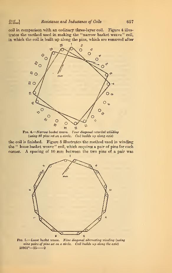
coil in comparison with an ordinary three-layer coil. Figure 4 illus-
trates the method used in making the "narrow basket weave" coil,
in which the coil is built up along the pins, which are removed after
O <*
O
Fig. 4.
—
Narrow basket weave. Four diagonal retarded winding
(using 25 pins set on a circle. Coil builds up along axis)
the coil is finished. Figure 5 illustrates the method used in winding
the " loose basket weave" coil, which requires a pair of pins for each
corner. A spacing of 10 mm between the two pins of a pair wast
p 9
Fig. 5.
—
Loose basket weave. Nine diagonal alternating winding (using
nine pairs of pins set on a circle. Coil builds up along the axis)
56961°—25 2

658 Technologic Papers of the Bureau of Standards r vol 19
used. Figure 6 shows the method used in making the "honeycomb '
'
coil. The zigzag winding is illustrated by the view of the entire
cylinder surface. The winding is built up along the radii of the coil.
IV. RESULTS
The results are exhibited in graphical form. Figure 7 gives
curves for the apparent self-inductance of the various test coils as a
function of frequency. As on all curve sheets, the dotted curves
indicate the different coils using No. 32-38 litz. It is seen that the
"loose basket weave" type of coil and the "single-layer" coils give
the lowest apparent inductance over the entire range of broadcast
frequencies (500 to 1,500 kc). This indicates that the coil capacity
is comparatively low, while the ordinary two-layer coil (E28) acts
more or less like a condenser, since the coil capacity is exceedingly
large.
3 » II 12 13 H 15 Kj 17 18 13 20 21 22 a 24 IS 1
2Ji;nME3 THLIN3J0L RA01W OT TWt OMU 1 — J
Fig. 6
Honeycomb coil. Four diagonal retarded winding Cross-section of winding(using 25 pins. Coil builds up along radius) frame with the 25 pins
Figure 8 gives the curves for the radio-frequency resistance. It is
seen again that the values of the resistance vary greatly. Naturally,
the ordinary two-layer coil (E28) has very large radio-frequency resist-
ance within the broadcasting range. Though its direct-current
resistance is only 2.75 ohms, the effective resistance at 500 kc is 162
ohms, at 580 kc it is 465 ohms, and at 748 kc it is 1,800 ohms. Theresistance increases very rapidly until it is mostly due to the dielectric
resistance across the insulation between the layers. A three-layer
coil wound in the ordinary way (ordinary multi-layer coil) and
adjusted, like all coils discussed in this paper, to 291 microhenries
at 1 kc has a radio-frequency resistance of several thousand ohms at
a frequency as low as 400 kc.
Figure 9 gives the curves for the ratio of the increase of the radio-
frequency resistance over its direct-current value to the direct-
current value. It is seen that the loose basket weave and the single-
layer coils have low values; next comes the radial basket weave coil,

/
520
510
500
490II
1
480
.470
'460
450
440
430
420
f\VI
_ ij
0>
ZT
410
400_
390
380
370
360
350
340_ *&/
3301
320
310
300
290
r8n_^^.
Mteis!f
Nil
280 I 1 1
CO 300 Aiso s DO
Fig. 7.
—
Apparent inductai


Zoo 300 Aoa soa 1200 1300 1400 woo£00 700 000 soo 1000 1100
KILOCYCLLS PER. SLCONDFig. 7.
—
Apparent inductance at (liferent frequencies (minimum inductance is 291 microhenries for all coils)
56901—25. (Face p. 658.) No. 1.


7o-
<0XI
- El,
20-
-28
2D0 joo 400 50O
Fig


aoo aoo 400 sea 600 700 aoo 900 1000 1100 1200 1300 noo I50O
KILOCYCLE.S PER SCCONDFia. 8.
—
Radio-frequency resistance at different frequencies
66961—23. (Face p. 658.) No. 2.


23
22
21
20
19
\&
P
16
T5
14
13
12
tl
10
6ELeb
2H
1 -
--'-'-T'
2tX> 300 -loo
Fig. 9.—Ratio of t


200'
300 «0O 500 600 ?«» *» *» 10CO "°°
KILOCYCLE.S PER. SECOND
Fig. 9.-fl««o of the increase of resistance over its direct^urrent value to the direct-current value
(too I3oo Moo isoo
56961—25. (Face p. 658.) No. 3


230r
Nl-A
DO.
-JftJ
30
- Lag
300 ,300 *?CO SOO


230
Fig. 10.
—
Ratio of inductance to resistance
66961—25. (Face p. 65S.) No. 4


Zoo 300 -4SJ© Soo
Fig. 11.
—
Percenta


ZOO 300 400 500 Goo 700 800 300 1000 1lOo 12oo 1300 I40O I.SX5
KILOCYCLES PER. SECONDFia. 11.
—
Percentage decrease in the ratio of inductance to resistance bi low the value at 1 kc
) Is'o. 5


Bund "1
Dt Grooti Resistance and Inductance of Coils 659
using hard rubber for the core, while the four-layer bank wound,
three-layer bank wound, and the honeyomb coils show considerable
percentage increases.
Figure 10 gives the curves for the ratio „• It is always smaller
than the ratio p2 at 1 kc. Since the apparent inductance and the
radio-frequency resistance increase with the frequency, this ratio in
certain cases has only small changes although both L and R are
changing rapidly. Nevertheless, these curves show about the samecomparisons as the resistance curves.
Figure 1 1 gives the curves for the percentage decrease in the ratio
o at different frequencies.
300
Fig. 12,
609 fa 8X> 300 fOoo Woo 12oo IJoo MOO 1500
KlUOCYCLflS PLR. SECOND—Radio-frequency resistance of single-layer coils

660 Technologic Papers of the Bureau of Standards [ Vol. 13
1. EFFECT OF THE KIND OF WIRE ON THE RESISTANCE OFA COIL
In order to show the effect of the size of the wire, curves for the
resistance for No. 28, No. 24, and No. 16 d. c. c. are plotted and
compared among themselves and against No. 32-38 litz.
These comparisons are shown in Figures 12 to 19.
ZOO 300 400 SCO 6oo 700 SCO S0O 1000 ]|00 1&0 1300 (*» I50O
KILOCYCLES- PER. SECOND
Fig. 13.
—
Radio-frequency resistance of loose basket-weave coils
It will be noted that in all cases litz, which corresponds roughly
to No.. 23 solid wire as regards its cross section, had the lowest
effective resistance. If solid wire is used, it appears unnecessary
to use wire larger than No. 24, although No. 16 gives, for the lower
frequencies, resistances which are slightly lower. Such a large
size of wire would, however, make the winding of certain types of
coils more difficult and the size of the finished coil too large for

Bund "I
De Qroot] Resistance and Inductance of Coils 661
convenient use in receiving sets. Figure 12 shows a single-layer
coil the turns of which are spaced by a distance equal to the diameter
of the wire. There seems to be no material reduction in resistance
except at the higher frequencies.
2» 300 400 500 600 -joo 800 300 100O tlOO 120O 1300 1400 tsoo
KltOCYCLE-S F£R. SECOND
Fig. 14.
—
Radio-frequency resistance of narrow basket-weave coils
2. EFFECT OF BROKEN STRANDS IN LITZ WIRE
The question is often asked concerning litz wire as to the effect
on the resistance of some of the strands being broken or not con-
nected at the respective ends.

662 Technologic Papers of the Bureau of Standards
Table 4.
—
Resistance of litz wire Nos. 32-88, at 750 kc
[Vol.18
Broken strandsResist-ance
Broken strandsResist-ance
Broken strandsResist-ance
Broken strandsResist-ance
o
Ohms3.13.23.23.33.33.33.43.5
8Ohms
3.63.83.84.24.44.44.44.7
16...
Ohms5.45.66.16.47.47.67.88.4
24
Ohmt9.5
9 17 25 10.8
2 10 18 26 13.5
3 11 19 27 14.4
4 12 20 28 16.5
5 13 . 21 29 21.7
g 14 22 30 42.4
7 15 23 31 51.6
Litz used is Nos. 32-38 and has 32 strands of No. 38 AWG enameled wire braided together.
19
1
5SffiS|Cr- '- 1;'-§'
^gj^p;||i
> elj|tip
nljljl""
4
"-"V$16BBS
15JJIJII
I4^Mc 55 SffifsssiiSSS'
telHIII
fh T| i
+
m[
y
ii
101
g^S|J±p
44tt TTTri!!
9J
^fffffff]Ifflj §11$1
J'|r ;f:
t|- j- TTmjrrrnt"
1 1 1 1 1 1
, jr-j/lf+tt-:"
rfipjjffiffl^
7|
;jg^Hv1 ! i E
\- ill VM $$&$ Hjl|}{
-SfajM ffOT
1:
: :
d-4-LL r-_ -j-.L
^T-.Biff 511
5
4;
::B||W|f i3: Lis',, Fdrfai *ia
uiniiiiiig
f§ '-rfyAc
1\
1 1 i ITT K<2»3»*»5»6«>7o9a»S0o iooo lloo ;a» 1300 Mao I5oo.
KILOCYCLES PER SECOND
Fig. 15.
—
Radio-frequency resistance of radial basket-weave coils

EundDe Groot
Resistance and Inductance of Coils 663
Table 4 shows that it is not so serious to have a few strands broken,
since the radio-frequency current apparently finds its way back
a» 300 400 5U> 603 700 sx> 300 1000 1100 1200 000 1400 UTOO
"KILOCYCLES PER SECOND
Fig. 16.
—
Radio-frequency resistance of honeycomb coils
across the strands. Even if, say, six strands are broken, the radio-
frequency resistance is 3.4 ohms as compared with 3.1 ohms for
perfect strands.

664 Technologic Papers of the Bureau of Standards [Voi.w
3. EFFECT OF BINDER ON THE EFFICIENCY OF COILS
The binders used in this test were each applied to a single-layer
coil, and just enough of it to cover the entire surface. The varying
nature of the different binders probably resulted in different thick-
2b030Q4O0 50O600'po$OO9OO 1000 1100 1200 1300 1400 1500
KILOCYCLXS PER, SECOND
Fig. 17.
—
Radio-frequency resistance of two-layer bank-wound coils
nesses. The coils in every case were dried thoroughly. The measure-
ments were a little difficult when a binder was used, even though
great care was taken to have the binder dried. For instance, in

Hand 1
De Groot] Resistance and Inductance of Coils 665
some cases the effective resistance of a coil using a binder came
out smaller by a fraction of an ohm than for the coil using no binder.
The binder seemed to make an accurate resistance adjustment more
difficult.
2)0 300 4C0 5£» 600 700 gfiO 900 1000 1I0O !200 1300 1400 1S00
KIU2CYCLE.S PEJZ SEjCONO
Fig. 18.
—
Radio-frequency resistance of three-layer bank-wound coils

666 Technologic Papers of the Bureav of Standards [Voi.is
Table 5.
—
Variation with frequency of radio-frequency resistance (in ohms) for
different binders
Frequency in kilocyclesAsb,
no binderQ28,
collodion
E28 f com-mercial
insulatingvarnish B
L/28, com-mercial
insulatingvarnish A
K28shellac
M28paraffin
300 - --- --- 3.94.45.15.9
ft 7
7.68.59.410.3
11.312.213.214.2
3.84.34.95.56.3
7.18.08.910.0
11.012.113.214.4
3.94.45.05.76.6
7.58.59.610.8
12.013.314.615.9
3.84.34.85.36.0
6.87.78.810.1
11.513.114.716.4
3.74.14.85.66.6
7.68.810.111.4
12.814.215.717.2
3.9
400 4.6
500 - -5.2
600 -6.0
700 - - 6.8
800 7.8
SOO _9.0
1,000 - - 10.3
1,100 11.8
1,200 - -- 13.3
1,300 - 15.0
1,400 16.7
1,600 18.5
Oolt+TTjf 1' : ±HHiH
SiJtjJi^iM ±S33jt : StJSSffiigjfftJHJ: ixtij
p§ffniTT[!Ii'HB+ft##
111
Stn ffittt1TT1 TO'WFpffljSQV-fttttltt-j
1.-jiijf! it;11H
T;-i
4-ffi|Jj^.#g
SWISlitS$i11|1<7 SfflS: !!
-
ipw/"
IIIIIIIH ] i'i rffrrn '|^J
filillill i M-\ fffffHt^if;iX|
!1 *i
!
:!' ; i'j
"H '
=Bi ¥ '
»
60 ISfaft r.
-\! :
'
'- ^S\i-'\
w,ffi ^^^B
gfigE: -- Ur-H '-' '~J\
"r"''
:;:\u.f£g|-jf
IlllllP;c ,
•
"TnTI : "Ht s£2 rtj: it 'Ah : mtt T 3
&IIIIJjiHk^H.mm 1
llllii : Si i iyffiBSSiplg|^S|l^pl§1IP
Bfrff H 1n H-lnft $\ irik.. i^w±S|p|S^
4>|||'£.' u
gpMpT&[i|||jlU.p:: -._
illiSMw 1MTI Off 1
. , 4 \\ raoffi^
$¥j |-
I::.'. :feS
"-,'
;
psfctj-iw1
'
ir|g*>i\ M1IIIIII S^r']'—co
1111111111£':'.
fftttitt
g^SP !1
!:,.[ '-1 '^j.
T T\ i\\V\\''r\^W\
lifcffi- # fffifff^^flrfff
10H
S» 300 400 506 600 700 Xoo 900 loco 110O 1200 1300 f4oo 1500
Fig. 19.
—
Radio-frequency resistance of four-layer bank-wound coils

J^gvoo*] Resistance and Inductance of Coils 667
V. SUMMARY
1. The various experimentally obtained curves given in this paper
can he used as design bases for comparing coils of six types for
any frequency in the broadcast range. For these data to apply it
is necessary that the coils be constructed in accordance with the
information given in Table 3. The coil dimensions are such that
the coils are applicable to modern broadcast reception. A statement
of the important characteristics of coils is given in the introduction.
2. The curves shown in Figures 9 and 11 give the changes of
resistance and of „ with frequency. High values of these ratios do
not in all cases correspond to high values of radio-frequency resistance.
In some cases, for instance, a particular coil has a relatively high
AT?value for -„-, although the actual radio-frequency resistance is not
large, because the direct current resistance is comparatively low.
3. The curves of Figures 8 and 10 give the actual radio-frequency
resistance and ratio of inductance to resistance at various frequencies.
4. Of the coils measured the loose basket weave coil and the
single-layer coil, and next to them the radial basket weave coil
wound on hard rubber, have the lowest radio-frequency resistance.
The four-layer bank-wound coil and the honeycomb winding havethe highest resistance. This can not, however, be generalized to
other frequency ranges. For instance, for low-frequency sets (20
to 100 kc) the multilayer bank-wound coil and the honeycomb coil
have relatively low resistance, and besides are good coils mechanically
while the loose basket weave coil has no special advantage and the
single-layer coil can not be used on account of excessive size.
5. There appears to be little reduction of resistance at the lower
frequencies in spacing the turns, so that the advantage of getting
a smaller resistance is small compared with the disadvantage of
requiring a coil twice as long.
6. The use of Nos. 32-38 litz gives coils of somewhat lower resist-
ance than coils wound with solid wire of the same cross section.
No. 24 AWG solid wire has less resistance than No. 28 wire, and No.
16 wire for a certain range has less resistance than Nos. 24 and 28
wire. If solid wire is used it does not appear necessary to use wire
larger than No. 24 AWG. This conclusion can not, of course, be
extended outside the broadcast frequency range; for instance, No.
16 solid wire would be better for frequencies above 5,000 kc.

668 Technologic Papers of the Bureau of Standards [Voi.19
7. All the insulating materials which were used as binders caused
very slight increases in the resistance of the coils. Collodion seems
best, and also has the inherent advantage of drying rapidly after
application to the coil. This is of especial advantage in the con-
struction of a bank-wound coil.
Washington, May 25, 1925.