comparison of american, british, and german...
TRANSCRIPT

DEPARTMENT OF COMMERCEBUREAU OF STANDARDSGeorge K- Burgess, Director
TECHNOLOGIC PAPERS OF THE BUREAU OF STANDARDS, No. 344
[Part of Vol.21]
COMPARISON OF AMERICAN, BRITISH,
AND GERMAN STANDARDS
FOR METAL FITS
BY
IRVIN H. FULLMER, Associate Physicist
Bureau of Standards
-
June 7, 1927
**'
:\W
PRICE 10 CENTS$1.25 Per Volume on Subscription
Sold only by the Superintendent of Documents, Government Printing Office
Washington, D. C.
UNITED STATESGOVERNMENT PRINTING OFFICE
WASHINGTON1927


T344
COMPARISON OF AMERICAN, BRITISH, AND GERMANSTANDARDS FOR METAL FITS
By Irvin H. Fullmer
ABSTRACT
A quantitative comparison is made among the tentative American, the British,
and the German national standards for metal fits. It is pointed out that the
American standard is a simplification of practice, by the selection of the practice
which meets the majority of requirements of interchangeable quantity produc-
tion. It is therefore much simpler than the European systems designed to cover
all types of machine construction. Each of the three national systems is briefly
described, and the basis upon which the comparison is made is outlined.
The fits of the American system are compared with fits of the Europeansystems having the basic hole and unilateral tolerances. Comparisons are madeby means of two diagrams. The first is a graph showing the relative positions
of the limiting dimensions of shafts and holes of the three systems for all diameters
from 0.2 inch to 10 inches. The second shows the tightest and loosest conditions
for each class of fit of the 1-inch and the 8-inch basic sizes. From these diagrams
a selection was made of the British and German fits corresponding most closely
to the American fits. A bibliography is appended covering recent literature
relating to metal fits.
CONTENTSPage
I. Introduction 401
II. Description of s}Tstems 402
1. American 403
2. British 403
3. German 404
III. Basis of comparison 404
IV. Corresponding fits in the American, British, and German systems 406
V. Bibliography 406
I. INTRODUCTION
This paper has for its purposes (1) the quantitative comparison, so
far as possible, of the tentative American with two outstanding
European national standards of tolerances and allowances for metal
fits—namely, the British and the German—selecting those types of
fits of the British and German systems which correspond in funda-
mentals to those of the American system, and by means of charts
showing the significance of the differences among them; and (2) to
select the particular fits of the British and German systems which
most nearly correspond to those of the American system. Other
comparisons among various national standards for fits, made from
somewhat different points of view, are cited in the appended
bibliography.
46919°—27 401

402 Technologic Papers of the Bureau oj Standards [ v& ti
In accord with present-day practices and tendencies in engineering
standardization and the elimination of waste in industry, the Ameri-
can standard tolerances and allowances for metal fits not only involve
the standardization of limits on dimensions of shafts and holes for
various classes of fit, but also a simplification of practice by the
selection of the one practice, out of several in use, which is based onthe needs of modern quantity production, which careful investigation
has shown to be the one most widely used, and the features of whichare such as to make for the greatest economy in production.
The practice selected as standard consequently has as its basis the
principles that (1) the tolerances on both shaft and hole shall be
unilateral; (2) the allowances necessary to secure various classes of
fit shall, whenever practicable, be applied to the shaft, and the
minimum hole shall be the basic size; and (3) the number of classes
of fit shall be the minimum number necessary to serve practical
purposes.
In the British standard, however, both unilateral and bilateral
tolerances and allowances on either or both shafts and holes are
provided, and the German system consists of two complete standards,
one on the hole basis and the other on the shaft basis, but in whichunilateral tolerances only are applied. Moreover, in both the
British and German standards a multiplicity of classes of fits is
provided.
These differences among the national standards here considered
arise from differences in prevailing practice. In England bilateral
tolerances are extensively used; however, the British Engineering
Standards Association recommends the use of unilateral tolerances
when such use does not conflict with predominating present practice.
Unilateral tolerances greatly predominate in the United States andare generally recognized as best suited for interchangeable quantity
production. The greater simplicity of the American standard is due
to the fact that it was drawn up specifically to meet most of the
requirements in interchangeable quantity production; whereas it is
recognized that there are cases, especially in other less preponderant
types of machine construction, in which the standard is not appli-
cable. On the other hand, the British and German systems are
intended to cover practically the entire field of machinery building,
less emphasis being placed on interchangeable quantity production,
which accounts for their greater complexity.
II. DESCRIPTION OF SYSTEMS
In order more clearly to understand the quantitative comparisons
among the three systems, the following brief descriptions are given:

Fullmer] Comparison oj Standards for Metal Fits 403
1. AMERICAN
Presented in report No. B4a-1925 of the American Engineering
Standards Committee, entitled " Tentative American Standard
Tolerances, Allowances, and Gages for Metal Fits." Eight classes
of fit are provided; namely, loose, free, medium, snug, wringing,
tight, medium force, and heavy force or shrink. Allowances are
applied on the shaft and for clearance fits are proportional to z^Jd
2, d
being the basic diameter. For interference fits the allowances are
such that the average interference 'of metal, by selective assembly,
is proportional to d. Tolerances on both shaft and hole are propor-
tional to 3V^ and the minimum hole is the basic size.
2. BRITISH
Presented in report No. 164-1924 of the British Engineering
Standards Association, entitled " Limits and Fits for Engineering/
'
No definite series of fits are specified, but series of hole and shaft
tolerances and allowances are given, leaving with the user the choice
of particular combinations of shafts and holes, of which there are
154 possible combinations, to produce desired qualities of fit. Toler-
ances and allowances are proportional to d 0Am (as nearly as could
be determined from the tabulated data on page 20 of the report)
and are determined by multiplying a range factor "r" and a size
multiplier "m," "r" being a constant for all diameters and "m" a
variable depending on the basic diameter. Range factors are
designated by capital letters; for example, unilateral holes desig-
nated as "B," "U," "V," and "W," have range factors of 0.0001,
0.0002, 0.0004, and 0.0008 inch, respectively. Bilateral holes are
designated as "K," "X," "Y," and "Z," and oversize holes, or
holes to which allowances are applied, as "A," "G," and "H."Shafts to which various allowances and tolerances are applied are
designated asaTT," "T," "S," "R," "Q," "P," "M," and "L,"
which He below the basic diameter; "B," "C," "D," "E," and "F,"which he above the basic diameter; and "K," which is bilateral in
relation to the basic diameter. Thus, a particular class of fit ob-
tained by combining some particular shaft and hole is designated bycombining the corresponding letters; for example, "UT." It is
recommended in the British report that such terms as "push fit,"
"close running fit," etc., should not be used, but that fits be specified
by the general names—"interference fit," "transition fit," or "clear-
ance fit." Also, although bilateral limits are given, the use of the
unilateral system as applied to cylindrical mating surfaces is recom-mended in cases where it does not conflict with predominating present
practice.

404 Technologic Papers of the Bureau oj Standards [Vol. ti
3. GERMAN
Summarized graphically in Dinormen 777 and 778, March, 1924,
of the Normenausschuss der Deutschen Industrie and for whichmaximum and minimum clearances and interferences are given in
Dinormen 152 and 153, July, 1925. There are two complete series
of fits, one on the hole basis and the other on the shaft basis. Also,
there are four general grades of fits, designated as Edelpassung,
Feinpassung, Schlichtpassung, and Grobpassung, corresponding, in
the hole-basis series, to hole tolerances of 1, lj^, 3, and 10 fit units
and in the shaft-basis series to shaft tolerances of 1, 1, 3, and 10 fit
units, respectively; one fit unit (Passeinheit) being equal to 0.005^5mm. By applying various allowances and tolerances to the matingmembers the following 22 classes of fit are obtained:
Edelpassung.
Feinpassung.
Edelfestsitz Excellent tight fit.
Edeltreibsitz Excellent drive fit.
Edelhaftsitz Excellent binding fit.
Edelscliiebesitz Excellent push fit.
Edelgleitsitz Excellent sliding fit.
Preszsitz Press fit.
Festsitz Tight fit.
Treibsitz Drive fit.
Haftsitz Binding fit.
Schiebesitz Push fit.
Gleitsitz Sliding fit.
Enger Laufsitz Close running fit.
Laufsitz Running fit.
Leichter Laufsitz Light running fit.
.Weiter Laufsitz Loose running fit.
!Schlichtgleitsitz Ordinary sliding fit.
Schlichtlaufsitz Ordinary running fit.
Weiter Schlichtlaufsitz Ordinary loose running fit.
(Grobsitz g x Coarse fit, g x .
HroS £::::::::::::::::: SEE It; tGrobsitz g t Coarse fit, g±.
Eleven additional classes of fit are obtained by cross combinations
of shafts and holes—as, for example, "Bohrungen der Feinpassungen
auf Schlichtwelle "—that is, fine fit holes on ordinary fit shafts.
III. BASIS OF COMPARISON
As the first step in making a quantitative comparison of the three
systems under consideration, bilateral tolerances and oversize holes
in the British system and the shaft basis in the German system have
been disregarded. This places all comparisons on the commonfoundation of the hole basis and unilateral tolerances, which are
fundamental in the American system. Having done so, there are
still two factors which complicate the making of comparisons, namely,
the large number of classes of fit in the foreign systems and the fact
that the allowances and tolerances in the three systems bear different
relations to the basic diameter. To attempt to superimpose on a


a.
m-30. Li
intpnrison <>j aft and hole di/iliusions


II
-wye-— .:y:
.;i'
Jg.UK '•{.•
ar;T^Hrr
J?SS^
PSLnufsitZ
fc"l a
H^ftfajjb
rW«^
.LN£%4hJiau5
=^^'iPW?ralbsJtt
^±~-nLJL_
/m:// 5/Z£-

Fullmer] Comparison of Standards for Metal Fits 405
single chart, with diameters as abscissas and deviations from basic
diameter as ordinates, the stepped lines representing variations in
fractions of an inch from the basic diameters, corresponding to the
allowances and tolerances, of all sizes of shafts and holes of the three
S3rstems would result in a hopelessly confused diagram, although
such a chart would present most completely the comparison desired.
Two distinct methods of plotting, therefore, were chosen, whichtogether appear to be adequate for making a satisfactory comparison
of the three systems, and the resulting diagrams are given herewith
as Figures 1 and 2.
As indicated in the above description of the systems, the tolerances
and allowances of each of the three systems are based on mathematical
formulas in which they are some function of the basic diameter.
This permits making a comparison on the basis of these formulas
rather than on the actual limiting dimensions for the various sizes.
Referring to Figure 1 : Inasmuch as all of the allowances and toler-
ances in the German system and the tolerances in the American
system are some function of the cube root of the basic diameter, it
was decided that the German fit unit, 0.005 y/d mm or 0.00057874
\/d inch, would be the most convenient unit for plotting. Accord-
ingly, the ordinates in Figure 1 are German fit units and the abscissas
are basic diameters in inches. Thus, all limiting dimensions which
are functions of \/d are represented by straight horizontal lines.
These include all of the German limiting dimensions, the limiting
dimensions of all holes in the American system, and the limiting
dimensions of shafts of classes 4 and 5 fits in the American system.
Those in the British system, being functions of d °-4375, are represented
by curves which throughout most of the range are nearly horizontal.
Limiting dimensions for classes 1, 2, and 3 shafts in the American
system, which are functions of d°-m7 , are represented by flatter
curves sloped at a somewhat steeper angle, and limiting dimensions
for classes 6, 7, and 8 shafts in the American system, which are
functions of d, are still flatter curves sloped at a still steeper angle.
In other respects Figure 1 is self-explanatory, but it should be men-
tioned that the "Preszsitz" (press fit) in the German system has
been omitted, for the reason that no mathematical basis for the
limiting dimensions of the shaft is given in the German standard
sheets available.
Figure 2 permits a more direct comparison of the actual quality
of fit as represented by the tightest and loosest conditions obtaining
for a given size for each class of fit. It is necessary merely to note
the various features of the chart without any preliminary analysis.
Comparison diagrams are given for two representative basic sizes;
namely, the 1-inch and the 8-inch. Plotted on a vertical scale for
each British combination of shaft and hole, for each American fit,

. JS. / __ ec/?.yf<American British rasi ??'r'^r WF-??.?.-,J.g!WLCAN BRITISH y_v. 8VT-SH wekican^gm*,™
„,
40919°—27. (Pncep.405.) No. 2
wmJJI -INCH SIZE Q-INCH SIZE
Fig. 2.—J idercumpurison of tightest and loosest conditions of fit

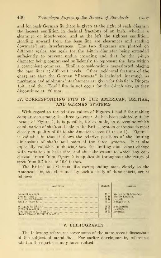
406 Technologic Papers oj the Bureau of Standards [ vol. tt
and for each German fit there is given at the right of each diagram
the loosest condition in decimal fractions of an inch, whether a
clearance or interference, and at the left the tightest condition.
Reading upward from the base line are clearances and reading
downward are interferences. The two diagrams are plotted on
different scales, the scale for the 1-inch diameter being extended
sufficiently to prevent undue crowding and that for the 8-inch
diameter being compressed sufficiently to represent the data within
a convenient compass. Similar considerations necessitated placing
the base lines at different levels. Other incidental features of the
chart are that the German "Preszsitz" is included, inasmuch as
maximum and minimum interferences are given for this fit in Dinorm152; and the "Edel" fits do not occur for the 8-inch size, as they
discontinue at 120 mm.
IV. CORRESPONDING FITS IN THE AMERICAN, BRITISH,AND GERMAN SYSTEMS
With regard to the relative values of Figures 1 and 2 for makingcomparisons among the three systems: As has been pointed out, bymeans of Figure 2, it is possible, for example, to determine which
combination of shaft and hole in the British system corresponds mostclosely in quality of fit to the American loose fit (class 1). Figure 1
is valuable in that it shows the relative positions of the limiting
dimensions of shafts and holes of the three systems. It is also
especially valuable in showing how the limiting dimensions change
with variation in basic size, and thus the extent to which any con-
clusion drawn from Figure 2 is applicable throughout the range of
sizes from 0.2 inch to 10.0 inches.
The British and German fits corresponding most closely to the
American fits, as determined by such a study of these charts, are as
follows
:
American British German
Loose fit (class 1) UTURBQB L
B BUEB E
Weiter Schlichtlaufsitz.Free fit (class 2) Weiter Laufsitz.Medium fit (class 3) Laufsitz.Snug fit (class 4).-. . Edelgleitsitz.
Wringing fit (class 5) . Edelhaftsitz.Tight fit (class 6) . Festsitz.Medium force fit (class 7) Preszsitz.Heavy force or shrink fit (class 81
V. BIBLIOGRAPHY
The following references cover some of the more recent discussions
of the subject of metal fits. For earlier developments, references
cited in these articles may be consulted.

FuUmer] Comparison of Standards for Metal Fits 407
"National standards for fits and gages," by John Gaillard. Machinery, 32,
August, 1926, pp. 927-932. Comparison of the standards established in the
United States, Great Britain, Holland, Sweden, Germany, Austria, andSwitzerland.
"Toleranser" (Tolerances), by H. Tornebohm. Teknisk Tidskrift, 54, October18 and November 15, 1924, pp. 109-113 and 121-125. Standard proposed bySwedish engineering standards committee for fits and tolerances of cylindrical
machine parts. Comparison with similar systems developed by other countries.
"Der Stand der Passungsfrage in Deutschland und im Auslande" (Status of the
fit problem in Germany and abroad), by K. Gramenz. Zeitschrift des Vereines
deutscher Ingenieure, 45, November 7, 1925, pp. 1411-1417. Compares stand-
ard fits of England, Italy, and Sweden with DIN fits.
"Engineering standards," by Earle Buckingham, and discussion. MechanicalEng., 47, July, 1925, pp. 555-559. Standardization in machine-shop practice
and conditions which a standard must meet; discussion of A. E. S. C. report
on " Tolerances, allowances, and gages for metal fits"; and discussion of stand-
ards for shafting, screw threads, etc.
"Requirements of a system of limits," by M. E. Steczynski. The Sibley J.
Eng., 38, June, 1924, pp. 139-146 and 155-156. A discussion of terminology
and of relative merits of the hole and shaft basis and of unilateral and bilateral
tolerances.
"A system of limits for different kinds of fits," by C. D. Albert. MechanicalEng., 47, November, 1925, pp. 901-903. Hole v. shaft as basis of fit system;best method of expressing tolerances; methods of expressing tolerances. Dis-
cussion by E. C. Peck, Mechanical Eng., 47, December, 1925, pp. 1165-1166.
"The advantages of unilateral tolerances," by E. C. Peck. American Machin-ist, 58, May 10, 1923, pp. 703-705. The economy of being able to use standardgauges; necessity of an unvarying zero point; comparison with the bilateral
system.
"Unilateral and bilateral tolerances as applied to interchangeable manufacture,"by H. W. Bearce. Mechanical Eng., 47, June, 1925, pp. 485-487. A discus-
sion of the two tolerance systems and their application to standard hole andstandard shaft practices; advantages of standard hole practice; specified
limits should not be exceeded.
"The unilateral system of tolerances," by Eugene C. Peck. Mechanical Eng.,
47, December, 1925, pp. 697-699. Need for national standard system of
dimensional tolerances; interchangeability defined; unilateral and bilateral
tolerance systems compared; basic hole or basic shaft.
"Limit gauging," by Sir Richard T. Glazebrook. Proc. Inst. Mechanical Eng.,
1920-2, pp. 1075-1124. A review of the development of limit systems in
Great Britain, followed b}* a discussion of the applications and measurementof gauges.
"Toleranzen" (Tolerances), by W. Kuhn. Veriag Verein deutscher Ingenieure,
Berlin, 1920. In two parts, the first being a general discussion of tolerances
and the second a discussion of screw-thread tolerances. In the first part a
hole basis system is proposed, based on a fit unit of qnnVd.
" Remarques sur le Systeme des Tolerances dans les Constructions MecaniqueA. C." (Remarks on the system of tolerances in mechanical construction). LeGenie Civil, 74, May 3, 1919, pp. 353-355. A discussion of theoretical toler-
ances based on the theory of probability, and of practical tolerances. Com-parison of s}7mmetrical and asymmetrical systems of tolerances. Abstractedin Mechanical Eng., 41, July, 1919, pp. 621-623.
Washington, February 5, 1927.