permeability of stone. -...
TRANSCRIPT

DEPARTMENT OF COMMERCEBUREAU OF STANDARDSGeorge K. Burgess, Director
TECHNOLOGIC PAPERS OF THE BUREAU OF STANDARDS, No. 305
Part of Vol. 20 ]
PERMEABILITY OF STONE
BY
D. W. KESSLER, Research Associate
Bureau of Standards
JANUARY 14, 1926
PRICE, 10 CENTS$1.25 PER VOLUME ON SUBSCRIPTION
Sold only by the Superintendent of Documents, Government Printing Office
Washington. D. C.
WASHINGTONGOVERNMENT PRINTING OFFICE
1926


T30S
PERMEABILITY OF STONE
By D. W. Kessler
ABSTRACT
The permeability of natural and artificial stone has been little studied in the
laboratory. Actual determinations of this property have been confined mainly
to concrete. The various means employed for this purpose have not been free
from criticism. This paper describes an apparatus which operates on somewhatdifferent principles than those heretofore employed and permits the use of a
considerable range in pressures. Since the permeability of the very dense ma-terials is small, it is desirable to use high pressures in experiments on such. Withthis object in view, some attention has been given to determining the variation
of the permeability of certain materials with the pressure. Since measurementsof this property have to be confined to relatively thin specimens it is of prime
importance to find out how the results of such tests apply to greater thicknesses
of the material. A limited number of tests have been made on a certain material
by varying the thickness of specimens. Six types of natural stone have been
tested for comparative data and to determine the adaptability of the apparatus
to a considerable range in textures.
CONTENTSPage
I. Introduction 155
II. Description of apparatus 156
III. Preparation of specimens 159
IV. Procedure 160
V. Results of tests 163
VI. Description of materials and individual tests 163
VII. Discussion of results 168
VIII. Suggestions for adapting the apparatus to various materials 169
IX. Application of results 170
X. Conclusions 172
I. INTRODUCTION
The permeability of a solid may be defined as that property which
permits any substance to penetrate or pass through it. In order to
compare the permeability of one porous material with that of another,
one may resort to measurements of the flow of some convenient fluid
through each under similar conditions. The permeability of stone
and similar building materials is usually conceived to be the rate at
which water will flow through. To accurately define this property
one may consider it as being the amount of water which will flow
155
Permeability, defined p.i 55lis elsewhere used inter-
changeably wit;, flow rate.
156 Technologic Papers of the Bureau of Standards [Voi.m
through a unit area of unit thickness in unit time under unit-pressure
difference between the two faces of the specimen. Due to the fact
that little work has been done to determine this property for stone
and that its accurate measurement is beset with several difficulties,
no attempt has been made in this study to establish a standard unit
of measurement. In order to establish a convenient unit that wouldbe applicable to a class of materials of such variable characteristics
it would be necessary to conduct an extended series of preliminary
experiments to determine the limiting values and eliminate some of
the uncertainties of the test. The data derived from the tests de-
scribed herein were obtained under various conditions for the purpose
of gaining some general information on this property.
The main purpose of this paper is to describe an apparatus whichhas been developed at the Bureau of Standards during the past year
for determining the water permeability of natural stone at various
pressures. Several tests have been made on various types of stone
in order to determine the adaptability of the apparatus to different
materials. Since very little information is available on the permea-
bility of stone, the determinations given herein may prove of interest
and serve to convey some idea of the variation of this property fromone type of stone to another.
Since the apparatus itself was an experiment, many of the parts
were adapted from stock materials in order to reduce the cost of
construction. Other laboratories have shown a desire to duplicate
this apparatus, hence a complete set of plans and description is in-
cluded in this paper as well as a detailed account of its manipulation.
As a permanent piece of laboratory equipment, certain improvements
could be made at a slight increase in cost which would simplify the
operation and give a more compact apparatus.
The writer wishes to express his appreciation to Dr. A. F. Melcher,
formerly of the United States Geological Survey, for valuable sug-
gestions concerning the design of the specimen holder.
II. DESCRIPTION OF APPARATUS
Since this apparatus may be found useful in the study of other
structural materials and various problems connected therewith,
a rather detailed description of its construction and operation will be
given.
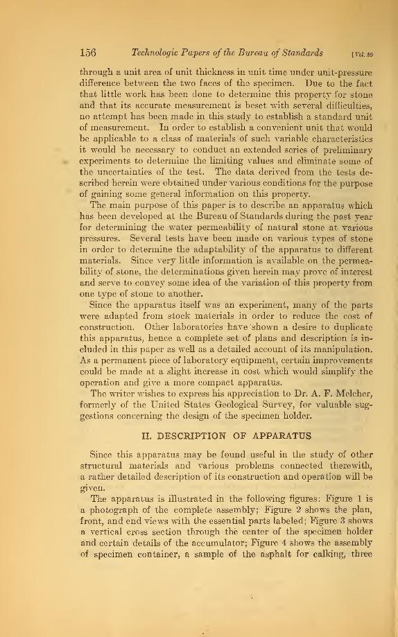
The apparatus is illustrated in the following figures: Figure 1 is
a photograph of the complete assembly; Figure 2 shows the plan,
front, and end views with the essential parts labeled; Figure 3 shows
a vertical cross section through the center of the specimen holder
and certain details of the accumulator; Figure 4 shows the assembly
of specimen container, a sample of the asphalt for calking, three

Technologic Papers of the Bureau of Standards. Vol. 20
Fig. 1.
—
Pholograph of permeability apparatus in operation

Kessler] Permeability of Stone 157
specimens broken under water pressure, and a collection of stone
specimens ready for testing.
The apparatus consists mainly of a heavy brass specimen holder
(D, fig. 2) and an accumulator for producing and maintaining the
A CHAR6IMS VESSEL- GALV. IRON
P VALVE - BRASSC Copper lead to specimen holderD Specimen holderE Pressure sage -5" DialF Bracket- 2 Read.6 8RASS KEV BLOCKH 1
" Pulley - Brass! Belt Iightener, 1 Jfe'DiA.. BrassJ PULLEV, 10'Di'A., WOOPK WEI6HT"C0NTAirlER-6AL</ (ROML Steel PlungerM Sturrng-box. brassN 1" Brass Pipe:
Pressure Pump!
J PistonR Copper lead from Accumulator to Prkj-
6 Pressure Line (ureLine7 Air- release ValveU Roller AxleV Va-" Round Leather Belt
5*- I3L75#Ckahnel, ZI'lohs
FRONT VJEW
Fig. 2.—PZcm, /ronZ and end views of apparatus with essential parts designated
desired water pressure. The specimen holder is made in three parts,
namely, the central part with a circular recess in which the specimenis placed, a cover plate which is clamped firmly to the central part,
and a cup-shaped vessel having a sharp-edged top of known diameterwhich can be screwed into the lower portion until the edge comesin contact with the specimen.

158 Technologic Papers of the Bureau of Standards [ Vol. so
The accumulator is connected to the specimen holder through
a pressure line, S (see fig. 2), by means of a strong, flexible copper
tube. A water-storage vessel, A, is placed at a high point for charg-
ing the system. Charging is accomplished by opening the valve
below this vessel and screwing back the pressure piston, P, to the
end of its cylinder. This draws a good portion of the system full of
water. The valve is then closed and the pressure piston screwed in
until a few pounds is registered on the gauge, E. Considerable air
will be trapped in the pipe which can now be discharged by means of
SEqiOMAL DETAIL of SPEC/MEtt HOLDER (D)
Note : All fwrrs to be made of brass
UMLZ55 OTHERWISE IHDICATECS
a^^DZ *- Leather Cup
DETAIL Qf PRESSURE PISTON (P)
.125" pitch Acme Threap
9-4IL.7-
DETAIL of FEED SCREW of PRESSURE PUMP(O)(Machime. Steel)
Fig. 3.
—
Transverse sections of specimen holder and parts of the accumulator
the valve, T. Alter this operation the system may be filled with
water by again opening the valve below the storage vessel and screw-
ing the pressure piston completely out.
Any desired pressure up to 300 lbs. /in. 2 can now be obtained by
placing the proper weight in the weight container, K. Shot is con-
venient for this purpose, and is easily distributed to prevent eccentric
loading.
No attempt was made in constructing this apparatus to obtain a
close-fitting plunger in the accumulator cylinder since this would
have required expensive machine work. The plunger, which is a
piece of cold-rolled steel, was turned and finished in the lathe to


Technologic Papers of the Bureau of Standards, Vol. 20
S9BHb ^^^r^l
Fig. 4.
—
Assembly of the specimen holder with a specimen calked in
place, a sample of asphalt used for calking, three specimens broken
by the water pressure, and a collection of stone specimens ready for
testing

Kesshr] Permeability of Stone 159
give a fairly snug fit. The water is held by means of a stuffing box,
M, which is packed with cotten wicking well lubricated with tallow.
This holds the water very effectively under the working pressures
with no appreciable leakage. However, the friction on the plunger
due to this packing is considerable, and in order to eliminate the
variation in pressure due to this a means is provided for revolving
the plunger while the test is in progress. This is accomplished by a
small motor and speed reducer which turns the large pulley, J. This
pulley revolves the weight container and plunger by means of the
vertical shaft which is rigidly fastened to these. This vertical
shaft was first grooved its entire length for a keyway, the key being
made rigid with the pulley, J. However, it was found that the
sliding friction on this key was so much that the pressures could not
be regulated and another means had to be adopted. This trouble
was overcome by mounting two brackets, FF, on tne pulley to form
runways for rollers on the roller axle, U, the latter being fastened to
the top of the shaft by means of the key block, G. While there is still
a small amount of friction due to this, it remains practically constant
and hence can be compensated for by a definite weight in the weight
container.
Another appreciable variation in pressure was found to occur if
the belt was placed around the pulley in the usual way due to pulliDg
this shaft to one side of the bearing. This was successfully over-
come by placing a small pulley, H, on the opposite side to the speed
reducer, as shown, to take the pull of the belt. A sliding pulley
opposite this, used as a belt tightener, gives a further equalizing
effect so that no appreciable variations were noted. In the operation
of the apparatus it was found that the pressures can usually be
depended upon to remain within 1 pound of that desired except whentests are being made on very porous materials. Under such con-
ditions the plunger has to drop rapidly due to loss of water through
the specimen and the pressure is apt to fall 3 or 4 pounds below that
desired. However, this could probably be overcome by increasing
the speed of rotation of the plunger. The speed used in these tests
was 10 revolutions per minute.
III. PREPARATION OF SPECIMENS
The type of specimen used in this apparatus is a disk 3 inches in
diameter which may be varied in thickness from three-quarter inch
downward to as thin as desired. These are prepared by cutting a
slab of stone of the required thickness and then cutting the disks fromthis by means of a 3-inch core drill. One face of the disk must be
finished by grinding to a smooth, plane surface.

160 Technologic Papers of the Bureau of Standards [Voi.m
IV. PROCEDURE
In preparation for the test the specimen is placed with the smoothface downward in the recess of the specimen holder. The clearance
of one-eighth inch between the edge of the specimen and the wall of
the holder is then filled with hot asphalt. It is best to bring the level
of the pitch one-eighth inch or more above the top of the specimenand when sufficiently cool press it against the wall of the holder,
forming a cove, as shown in Figure 4. An asphalt which gaveexcellent results for this purpose was an 83° C. melting point oil-
blown asphalt which is commonly used for roofing purposes. A lowermelting point pitch was tried and found unsatisfactory in warmweather, as it would sometimes flow under the higher pressures andpermit leakage. De Khotinsky cement was also tried with unfavor-
able results. It was found that the setting of the specimen could bedone more satisfactorily by heating both it and the container on a
hot plate for several minutes before pouring the bitumen.
When the specimen is calked in place and the pitch has cooled
this part of the apparatus is supported on a strong ring stand andclamped to the cover plate. The system is charged with water as
previously described and when a few pounds' pressure is brought
upon the specimen the cup-shaped part is screwed into the bottomuntil it makes a firm contact with the specimen. When the full
pressure is brought on the specimen the contact with the top of the
cup will be made firmer due to the deflection of the disk.
Most of the materials experimented with were found to be perme-
able enough so that the water could be measured with sufficient
accuracy in an ordinary graduate reading to 1 cc. Dense stones
like granite, slate, and some others showed such a small percolation
even at high pressures that more accurate measurements were
necessary. In such cases a small vessel fitting snugly into the cupwas filled with anhydrous calcium chloride to absorb the moisture as
it came through. By weighing the desiccant before and after the
test very small amounts of moisture could be measured.
In working on materials of rather coarse textures it was found
that the contact obtained by simply screwing the cup-shaped part
of the apparatus against the lower surface of the specimen was not
satisfactory, since the larger pores and cavities in the stone wouldallow water to flow past the edge of the cup and cause the readings
to be either too high or too low. This difficulty was overcome in
the following manner: After the specimen was calked in place for
the test a thin layer of graphite was rubbed on the sharp edge of
the cup, which was then screwed into its position until it made con-
tact with the specimen, then removed again. This marked a circle
on the specimen which indicated where the contact was made.

Kesshr] Permeability of Stone 161
A watch glass about one one-hundredth of an inch less in diameter
than the top of the cup was then centered in the circle with the con-
cave side next to the specimen. By means of a small bristle brush
a narrow rim of hot paraffin was painted on the specimen around
the edge of the glass. When cool, this was cut loose from the glass
with the point of a knife. This formed a narrow band of paraffin
which the sharp edge of the cup could be screwed into. The paraffin
served to fill the pores of the stone and prevent the flow of water
along the lower side of the specimen into or outside of the cup.
This means may introduce a slight error in determining the area
over which the flow is measured, but it is probably insignificant
compared with the natural variation in the stone itself from one
specimen to another.
The time interval for measuring the rate of flow was varied,
depending on the rate at which water penetrated. In the moreporous stones it was found necessary to take observations each minute,
while with the dense materials the interval was increased to two hours
or more. In the reduction of the data all values were computed for
the flow in cubic inches per hour for 1 square foot of stone surface.
70660°—26| 2

162 Technologic Papers of the Bureau of Standards f Vol. SO
I I
$5 ©
-a
O »<» u.
t 1S. 44
^ IS
42 s3 aCO
1 s|
aow1=1
a- aA< aH S.
o
as,
tOOO
8§888
:s
oooo©<O00<NrtNNN
gs;
III £o««« Stj-, . +a .COo o o ega£ H 53.5Mot bO coT3P C3 ce fl
PQ02PQ oqPh
S § £ cs ce
§.§§ §8Sfi>oS £>Q
o iws
a §
bbS3!
bs, , H
»'"'•"eB
© 05X3
^sagoo3*S'S o/o
3Mla-o o
a> 05 ot
®.2 ?>§a :So
03 03
«aDOS
pSS<i :§ ifiS
! el '
IC<tC0-*iO ©N00»O

Kessier) Permeability of Stone 163
V. RESULTS OF TESTS
Table 1 shows the results of permeability tests on six types of stone
expressed in cubic inches per minute for 1 square foot of area. Thespecimens were one-half inch thick except as otherwise noted in the
column under "Kemarks." The low pressure of 1.2 lbs./in.2 was
that due to the head of water above the specimen in the apparatus,
while the other pressures were chosen to suit each particular case.
Tests Nos. 17 and 19 were made at several pressures to determine the
variation of permeability with the pressure, and 17 and 18 were
made with a view of determining the variation with the thickness of
specimen.
An adequate description of the materials in the table was not
possible, so these notes, together with certain physical data of interest,
have been placed in the following section. Since it is desirable to
compare the permeability values with the results of absorption tests,
the ratio of water absorption to permeability at 100 lbs./in.2 has
been computed so far as the latter values are available and expressed
as " ratio a/p." These data are included with the physical data in
the following section.
VI. DESCRIPTION OF MATERIALS AND INDIVIDUALTESTS
Due to the fact that all of the descriptive data concerning the
materials tested could not be included in the table of results, this
section is added to include the notes of general interest. The serial
numbers used herein refer to the corresponding numbers in the first
column of the table.
The pressures used in the different tests were entirely arbitrary.
The lowest pressure used was that due to the head of water in the
pipes and charging bucket. The higher pressures were chosen to
give a convenient range as far as the nature of the different materials
would permit.
1. This is a biotite granite from the Colorado Canyon, Nevadaside. It has a large percentage of quartz which is interspersed with
fine flakes of mica.
Physical properties:
Water absorption (by weight) . per cent__ 0. 3
Ratio a/p 1. 07
Apparent specific gravity 2. 65
Compressive strength lbs./in.2__ 22, 000
Due to the density of this material, the rate of penetration wasvery slow, and the time between measurement was from two to three
hours for. all, except the low pressure, which was continued for 17
hours.

164 Technologic Payers of the Bureau of Standards [voi.go
2. The specimen was a dense dioritic granite from the Colorado
Canyon, Nevada side.
Physical properties:
Water absorption (by weight) per cent-. 0. 3
Apparent specific gravity 2. 77
Compressive strength lbs./m-2-- 28, 000
The very slow rate of penetration and the slight increase from 1.2
to 125 pounds renders the results rather uncertain as individual
values, but all testify to the fact that the material is only slightly
permeable.
3. A volcanic breccia from the Colorado Canyon, Arizona side.
This material consists of angular fragments from an inch in size to
very small pieces firmly embedded in a fine matrix.
Physical properties:
Water absorption (by weight) per cent__ 2. 6
Apparent specific gravity 2. 46
Compressive strength lbs./in. 2__ 14, 000
Considering the proportionally large absorption of this material
as compared with the granites, a higher rate of penetration might be
expected.
4. This is a mica slate from Granville, N. Y., of green color andfine crystalline texture, containing a high percentage of quartz.
Physical properties:
Absorption (by weight) per cent. _ 0. 2
Ratio ajp 1. 82
Apparent specific gravity 2. 76
Modulus of rupture lbs./in. 2__ 11, 000
The results indicate that this is the most nearly impermeable
material tested.
5. A dark-colored mica slate from Pen Argyl, Pa., containing a
rather high percentage of calcareous material.
Physical properties:
Absorption (by weight) per cent__ 0. 47
Apparent specific gravity 2. 78
Modulus of rupture lbs./in. 2__ 8, 000
The values obtained for this material compare very well with
those obtained for the other sample of slate.
6. A fine-grained, dense calcite marble from Gantts Quarry, Ala.
This specimen was prepared so that the penetration was parallel to
the natural bedding of the material. It was pure white and free
from veining effects.
Physical properties:
Absorption (by weight) per cent- _ 0. 08
Ratio ajp . 07
Apparent specific gravity 2. 72
Compressive strength lbs./m-2 -- 14, 000

Kessier] Permeability of Stone 165
At the low pressure this material appeared to be of the same order
of permeability as granite but considerably higher under greater
pressures.
7. This specimen was prepared from the same piece of marble as
that for test No. 6, but included a few green schistlike veins. Theobject of this test was to determine if the veined portion was morepermeable. The results indicate somewhat lower values than the
entirely white portion.
8. A slightly buff, dolomitic marble from Cockeysville, Md. Thespecimen was of uniform composition and medium texture.
Physical properties:
Absorption (by weight) per cent_ _ 0. 10
R,atio afp . 005
Apparent specific gravity 2. 86
Compressive strength lbs./in.2 _ _ 22, 000
The four determinations on this indicate approximately a straight-
line variation of the permeability with the pressure.
9. This test was made on a specimen of the same material as No.
8, which was treated with two coats of 45° C. melting point paraffin
dissolved in benzol. The strength of the solution was approximately
10 per cent by weight. The results indicate that the treatment
reduced the permeability approximately 81 per cent at the low
pressure and 99 per cent at 150 lbs. /in. 2
10. This is a coarse-grained calcite marble from Ball Ground, Ga.
The specimen was of uniform composition and texture.
Physical properties:
Absorption (by weight) per cent _ _ 0. 10
Ratio alp . 004
Apparent specific gravity 2. 72
Compressive strength lbs./in. 2__ 10, 000
In this test there appears to be an inconsistency, since there wasvery little increase in permeability indicated from 100 to 200 pounds.
11. A test on the same marble as No. 10 treated with two coats of
a 10 per cent solution of 45° C. melting point paraffin dissolved in
benzol. The waterproofing result was very good, since all tests
indicate a reduction of permeability of more than 98 per cent.
12. A very fine-grained, compact, dolomitic limestone from
Joliet, 111.
Physical properties:
Absorption (by weight) per cent__ 2.
Ratio alp 2. 1
Apparent specific gravity 2. 63
Compressive strength lbs./in.2-- 22, 000
It is worthy of note that the permeability of this limestone is less
at the higher pressures than two of the marbles and practically the
same as the least permeable one.

166 Technologic Papers of the Bureau of Standards [Voi.no
13. This is a light-colored oolitic limestone of uniform texture
from Russelville, Ala.
Physical properties:
Absorption (by weight) per cent__ 4. 9
Ratio a/p . 31
Apparent specific gravity 2. 34Compressive strength lbs./in. 2__ 7, 300
The results approximate a straight-line variation of the permea-bility with the pressure. This limestone has a very low resistance
to frost action, and hence it is a matter of interest to compare the
permeability and other physical properties of this with the samevalues of other materials which are more resistant. The permea-
bility of this material is less than the marble used in test No. 10, yet
the absorption of the marble is only one-fiftieth of that of the limestone.
This seems to be a logical explanation of the poor frost resistance of
this limestone; that is, a high absorption and relatively low permea-
bility. An analogy of common occurrence is the freezing of a bottle
of milk in winter. The stopper offers little resistance to the expan-
sion when freezing occurs so the frozen milk forces its way out andstands an inch or more above the top of the bottle. On the other
hand, if a' water pipe with closed valves freezes the pipe is sure to
burst.
14. A bluish-gray, fine-grained dolomite from Mantorville, Minn.
This limestone has frequent large pores and occasionally cavities an
inch or more in size. The specimen was prepared to include only the
material which was practically free from these large void spaces.
Physical properties:
Absorption (by weight) per cent. _ 4. 5
Ratio a/p . 28
Apparent specific gravity 2. 40
Compressive strength lbs./in.2__ 12, 000
The tests indicated that some of the larger pores conducted water
very freely, and three specimens were tried before one was found
which was free from large continuous pores.
15. This is a yellow arenaceous dolomite from Kasota, Minn.
Physical properties:
Absorption (by weight) per cent__ 3. 2
Ratio a/p . 37
Apparent specific gravity 2. 53
Compressive strength lbs./in.2__ 20, 000
The specimen was prepared so as to indicate the permeability
perpendicular to the direction of the bedding.
16. A dolomite limestone from the same locality as that used in
test No. 15 and differing from it mainly in color. This was of the
pink variety.

Kessier] Permeability of Stone 167
Physical properties:
Absorption (by weight) per cent__ 3. 3
Ratio a/p . .03
Apparent specific gravity. 2. 53
Compressive strength lbs./in. 2 _ _ 20, 000
The specimen was prepared so as to indicate the permeability
parallel to the bedding.
17. This was a specimen of medium-texture Indiana limestone
from the vicinity of Bedford.
Physical properties:
Absorption (by weight) per cent_ _ 4. 1
Ratio a/p . 002
Apparent specific gravity 2. 34
Compressive strength lbs./m. 2_ _ 7, 000
Measurements were made at several pressures to determine the
law of variation. Figure 5 shows the curve obtained which is ap-
proximately a straight line.
18. A specimen of the same limestone used in test No. 17. Thepiece was made just twice as thick as the former in order to indicate
the variation in permeability with the thickness. The results in-
dicate that by doubling the thickness the permeability is reduced byabout one-third.
19. A very fine-grained compact sandstone from McDermott,Ohio.
Physical properties:
Absorption (by weight) per cent__ 6. 5
Ratio a/p .03
Apparent specific gravity 2. 21
Compressive strength lbs./in. 2__ 9, 000
Measurements were made at several pressures in order to deter-
mine the law of variation. The results are shown in Figure 5. Withthe exception of the determinations at the lower pressures the varia-
tion approximates a straight line. Further discussion of this test is
made in the section relating to the general discussion of results.
20. This was a sample of medium-texture sandstone from Amherst,
Ohio. This sandstone consists mainly of a compacted sand which is
relatively free from cementing material.
Physical properties:
Absorption (by weight) per cent__ 6. 5
Apparent specific gravity 2. 16
Compressive strength lbs./in. 2__ 8, 000
The specimen was prepared to indicate the permeability perpen-
dicular to the bedding. The flow was so rapid that no saitsfactory
measurements could be made under pressures greater than 25 pounds.
This was by far the most permeable material experimented with in

168 Technologic Papers of the Bureau of Standards [Vol so
this group. This stone has been extensively used in building con-
struction for many years and has shown unusually good weathering
qualities. It also indicates a high degree of resistance to frost
action in the laboratory tests, which fact adds to the evidence pre-
viously obtained that a durable stone must have a permeability
commensurate with its absorption.
VII. DISCUSSION OF RESULTS
6000
5000
4000
3000
^2000
£ 1000
\
f1
•i
600
500
400\-
300
1 1 1 1
Bedford Limestome_ Specimen % "thick
(£achpo/nton the curve_ is averaae of3 tests)
^wCurve for SiSne/s^om, f//o»vnfrvbh
aratvrr ¥o /his jaa/e fbrcompar/serr'y^
The actual permeability under high pressures seldom comes into
consideration in the use of stone. When stone is used in high damsof the arch type, which
design permits the use
of relatively thin walls,
the question of actual
water penetration maybe an important one.
With this in view, someattention was given to
determining the rela-
tion between the per-
meabilities of thick andthin specimens. Test
No. 18 in the " table of
results " gives values
obtained on a specimen
of limestone three-
fourths inch thick, and
test No. 19 gives the
values for the samematerial prepared into
a specimen three-
eighths inch thick. Acomparison of the de-
terminations indicates
that by doubling the
ZOO
100
01
1 1 1 1 1
McDERMOTT,OH(0, SflNPSTOnE- dpec/mens '/z" thick
(tact? point on the curye is
_ averaae offrom 2to3 tests. )
Z5 50 15 100 125 150 175 200 225
Water-pressure, Jb. perse/: in.
Fig. 5.
—
Variation of permeability with the pressure
thickness of stone the permeability is reduced by approximately one-
third. This ratio is based on a limited number of determinations
and should not be given too much weight, but it is believed to be
of some value in the absence of other data on the subject.
The main reason for determining the permeability under pressure
is to secure values which are of greater magnitude. This enables
one to secure measureable quantities in a shorter period of time, but,
since the values of most interest are those for low pressures, it be-
comes necessary to determine the law of variation of water flow
under different pressures. While measurements were made on a

zessJer] Permeability of Stone 169
number of specimens for three or more pressures only two were de-
termined for a sufficient number of pressures to justify the plotting
of curves. Tests 18 and 19 were made for several pressures and the
curves for these are shown in Figure 5. The test on Indiana lime-
stone indicates a linear variation. That part of the curve for the
sandstone which deals with the higher pressures also indicates the
same variation, but the first part indicates a retarded flow. This is
believed to be due to the fact that in the first few measurements all
of the pores had not come into action, and the values obtained were
only for the larger pores. This is a very fine-grained, dense stone,
and it seems probable that the finer pores would be slow in becoming
filled. There is evidence of this in some tests which were repeated
a number of times at the same pressure. The values increased for a
time after the water started to flow, then after reaching a maximumthere was a slight decrease in the rate. A test on limestone repeated
for 30-minute intervals at the same pressure gave the following
results
:
cc
First 30 minutes 5.
Second 30 minutes 5. 2
Third 30 minutes 5. 7
Fourth 30 minutes 5. 6
These figures indicate an increase in the rate up to one and one-
half hours, after which a slight drop was noted. The decrease in
rate is probably due to stopping of the pores either with loose parti-
cles of the stone or with suspended particles of solid matter or organ-
isms in the water. On this account it appears desirable to use
distilled or filtered water in making such tests when more precision
is required. However, when the natural variation in the stone is
taken into account it is doubtful if this would be justified if it is only
desired to compare the permeability values of different materials.
Since there appears to be an increase in the rate of flow of water
through a material for several minutes after the test is started, it
seems advisable to adopt a standard procedure governing the time
of measurements. No attempt was made in this study to determine
the variations in permeability with the time for all the materials. It
seems likely that the denser materials like granite and slate wouldshow an increase in permeability over a longer period than the moreporous materials due to the fact that the minute pores would becomerilled very slowly.
VIII. SUGGESTIONS FOR ADAPTING THE APPARATUS TOVARIOUS MATERIALS
In designing this apparatus one objective was to eliminate some of
the uncertainties which exist in other types due to the use of gaskets.
The scheme devised for calking the specimen into a suitable holder
and then measuring the flow through a definite area at the center

170 Technologic Papers of the Bureau of Standards [ vol. to
appears to attain this object satisfactorily for use on several types of
material. However a slight modification of the means for deter-
mining the amount of water in case of some materials is necessary.
The densest materials allow such a small amount to pass throughthat it can be absorbed in a desiccant placed near the specimen in
the measuring cup. Somewhat less dense materials are too perme-able to permit all the moisture to be absorbed in this way, but still
the amount may be too small to measure by volumetric means.For such materials a drying system can be attached to the measur-
ing cup by making two vents for tube connections. Such a system
is frequently used in various laboratory processes and consists of a
means for drawing a stream of air, first through a desiccant to dry
the air, then through the chamber or material of unknown moisture
content, and finally through a series of tubes containing a desiccant.
The latter series of tubes is so arranged that it can be readily re-
moved and weighed to determine the increase or amount of moisture
in question.
Some of the tests made with this apparatus on thin pieces of slate
and some dense marbles were found unsatisfactory because the
means used did not absorb all the moisture. The drying system
described above is suggested for use on such materials. With this
addition and the use of the scheme previously suggested for very
porous materials the apparatus can be used satisfactorily on the
entire range of textures found in natural stone or similar materials.
Due to the need of a satisfactory means for testing the permeability
of concrete, brick, terra cotta, etc., and the effect of waterproofings,
some thought has been given to the use of this type of apparatus on
such materials. Since the range in textures covered by the experi-
ments reported herein corresponds very well with the usual range in
artificial materials, it seems likely that the apparatus can be readily
adapted for any of these. However, for some materials it may be
desirable to enlarge the dimensions of the specimen holder in order
to use larger specimens. For use on concretes with various aggre-
gates a specimen holder has been constructed at this bureau. This
utilizes a specimen 6 inches in diameter, which can be made in
various thicknesses up to 2 inches.
IX. APPLICATION OF RESULTS
Absorption and porosity determinations are frequently made on
stone and are considered of importance in connection with other
laboratory tests. Permeability determinations are believed to afford
information of value in connection with many of the uses of stone.
In the case of a stone wall in a building the amount of moisture
which can pass through to the interior is of more immediate impor-
tance than the amount the wall will absorb. Several problems in
connection with masonry structures are concerned more or less

Kesshr] Permeability of Stone 171
directly with permeability, and hence a brief discussion of these
problems may be justified.
1. Efflorescence on masonry is in most cases caused by water
leaching through, dissolving water-soluble constituents and carry-
ing them to the surface where they crystallize, with many ill effects.
Due to the fact that a portion of the crystallization takes place in
the pores of the stone near the surface, an action similar to that of
frost occurs. This action is so severe that disintegration of the
stonework frequently results. The leaching water may originate
from rains or thawing snow which percolates downward through
the coping, cornice, sills, etc., or it may proceed upward from the
ground by means of capillarity, in which case it shows its effects on
a few courses of stone above grade. Frequently a denser stone is
used below grade and carried somewhat above grade to overcome
this trouble. It appears that efflorescence could be overcome
almost entirely by using dense stones in the coping and other parts
where water readily finds its way into the walls.
2. Weathering of stone is usually considered to be due to frost
action or the chemical action of the elements. If water did not find
admittance to the interior of the stone the effect of freezing tempera-
tures would be almost negligible. An examination of old stone
buildings will usually show the greatest weathering effect where
water has had the best chance to penetrate. Projecting courses of
porous stone as, for instance, the cornice and coping, take up water
which soaks downward through several courses of stone below.
Such parts of a building suffer severely, not alone from frost action
but also from the more severe disintegration effects of efflorescence.
Bridge piers of porous stone standing in water are subjected to
severe weathering for several courses above the water line, due to the
fact that moisture is continually creeping upward by capillarity.
Probably the best way to avoid such a condition would be to use a few
courses of dense material from the low-water level to slightly above
the high-water level.
3. In studying the weather-resisting qualities of stone it is prob-
ably more important to determine the nature of the pores than the
actual amount of pore space. It has long been the hope of investiga-
tors working along the line of weather-resisting qualities of stone to
discover some simple but reliable means which can be used to deter-
mine the difference between a stone of enduring properties and one of
poor quality. Actual weathering tests are expensive and few labora-
tories are equipped for making them. It has been suggested that
a study of permeability might lead to a better understanding of the
structure which determines the weathering qualities. This idea has
probably never been given a fair test, but evidence exists in some of
the permeability results herein that the ratio between the total
absorption of a stone and its permeability may have some significance

172 Technologic Papers of the Bureau of Standards [voito
in this respect. The ratio between the absorption value and the
permeability at 100 lbs./in. 2 has been computed for several materials
and included with the other physical data in Section V. An examina-
tion of these values for comparison with the available data on weather-
ing qualities indicates that no definite limit for this ratio could beestablished which would apply to all types of stone. For instance,
the ratio is relatively high for granite and slate, which materials are
the most resistant to weathering. However, on comparison of the
ratios for materials of similar properties, as Nos. 10, 13, 14, 17, and
19, it will be seen that the second two of these show relatively high
ratios while the others are low. The resistance of materials Nos. 13
and 14 to frost action has been found to be low, while that for the
other three is high. The resistance of samples Nos. 12 and 15 has not
been established, but the high strengths of these materials would be in
favor of greater resistance.
4. Waterproofing is frequently resorted to as a means of preventing
dampness and also as a means of overcoming frost action, discolora-
tion, etc. Numerous materials have come on the market and are
extensively sold for the purposes mentioned. Little information is
available concerning the relative merits of different types of surface
applications, and such materials are usually purchased on the recom-
mendation of the producer. There is an urgent need for moreinformation on the merits of such products. Evidently the real test
of any waterproofing is its effect in permanently sealing the pores.
X. CONCLUSIONS
1. The apparatus described has been experimented with upona range of materials varying from very dense to very porous and found
to give satisfactory results.
2. Tests have been made on specimens of six types of natural stone
which serve to indicate the relative permeability of these types.
3. A limited amount of work was done in determining the value of
a penetrating waterproofing material on marble which indicated that
the permeability can be reduced 98 per cent by this means.
4. The tests, in general, indicate that the relation of permeability
to the pressure is approximately a straight-line ratio.
5. A limited number of tests were made to compare the permeability
of specimens of different thicknesses. These indicated that by dou-
bling the thickness the permeability was reduced by approximately
one-third.
6. A discussion is made of the applicability of permeability tests to
certain problems arising from the use of stone under various condi-
tions.
Washington, July 29, 1925.