quantum chemical simulations of hole self-trapping in semi
TRANSCRIPT

INTERNATIONAL JOURNAL OF QUANTUM CHEMISTRY, VOL. 52, 1177- 1198 (1994)
Quantum Chemical Simulations of Hole Self-Trapping in Semi-Ionic Crystals
L. KANTOROVICH* Departamento Quimica Fisica y Analitica, Universidad de Oviedo, 33006-Oviedo, Spain
A. STASHANS AND E. KOTOMIN The Institute of Solid State Physics, The University of Latvia, Rainis Blvd. 19, Riga, LV-1050, Latvia
P. W. M. JACOBS Chemistry Department, The University of Western Ontario, London, Canada N6A 5B7
Abstract
A novel formalism is presented for reliable calculations of the energetics of hole self-trapping in semi-ionic solids with mixed valence bands. Unlike previous model-Hamiltonian-type approaches, it is based on self-consistent quantum chemical INDO simulations of the atomistic and electronic structure of a self-trapped hole, making no a priori assumptions about a particular form of its localization (if any). This formalism is applied to the problem of hole self-trapping in corundum crystals ( a -A1203). The hole self-trapping is found to be energetically favorable in the form of a diatomic 0 2 molecule with strong covalent bonding quite similar to the self-trapped hole (VK-center) in alkali halides. The so-called localization energy (i.e., the energy that is required to localize the Bloch-like wave packet of the free hole on the molecule, as the first stage of further trapping) is essentially less than one-half of the upper valence hand width, which is the estimate commonly used for ionic solids. 0 i994 John Wiley & Sons, Inc.
1. Introduction
Since 1933, when Landau predicted theoretically the self-trapping of charge carriers in perfect ionic crystals, considerable effort has been devoted to confirming this experimentally [I-71. For holes in alkali halides, it was found in 1955 by Kanzig [8] by means af EPR that the self-trapped (ST) holes (STH) have the structure of X , quasi-molecules oriented along the (1 10) axis of the crystal ( X - denotes a halogen ion). In the case of pure oxide crystals, the hole is believed to be trapped by one or several oxygen atoms. Use of EPR here is complicated by the zero nuclear spin on regular 0 atoms. At present, the existence of hole centers has been established in a set of oxide crystals only near a cation vacancy or impurity [6].
Nevertheless, an experimental technique developed in the 1970s [9] has been used to detect reactions controlled by small-polaron motion and their subsequent tunneling recombination with electron centers by monitoring the transient kinetics of the decay of recombination luminescence in irradiated insulating solids. This method indicated the existence of small polarons in a number of materials, including pure a-Al2O3 (corundum crystals) [lo, 111. However, the
*On leave from The Latvian Medical Academy, Dzirciema 16, Riga, LV-1007, Latvia.
0 1994 John Wiley & Sons, Inc. CCC 0020-7608/94/051177-22
1178 KANTOROVlCH ET A L
interpretation made in [ 10, 111 did not find universal acceptance [12]. Therefore, the problem of whether the STH exists in pure oxide crystals or not has for many years remained an open question [12,13].
To decide whether the STH is energetically preferred to a free-hole state in a given material, it is necessary to calculate the so-called self-trapping energy [14-201, i.e., the difference
where EST is the hole energy for the fully relaxed ST state, while EF) is the energy of the free-hole state at the bottom of the free hole band. If AEsT is positive, the self-trapping does not occur, but if it is negative, the hole can be trapped spontaneously, forming a hole defect, since this is the energetically more favorable state. The larger the absolute value of the negative ST energy, the larger the lifetime of the hole in the ST state rather in a free-band state. Considering different possible (stable) ST states (if any), a number of different ST energies could be calculated, and therefore their comparative trapping probabilities could also be estimated.
Though the physical grounds for a conclusion concerning the ST state are clear enough, there is a practical difficulty in calculating the ST energy [15,20]. Indeed, the localized (ST) and the delocalized (free) states cannot be considered in practice by means of the sanze method of calculation, allowing us to take carefully into account both the short-range chernicul structure of the ST hole and long-range effects characterizing the free hole.
A candidate for that universal method would be the model Hamiltonian (MH) method based on the pioneering ideas of Toyozawa [I91 and applied to the study of ST holes in alkali halides in [21-231. However, at present, such a method does not allow us to take into account the microscopic structure of the STH, though, as is known from detailed quantum chemical calculations of the STH in alkali halides (VK-centers) [17,24], that significant redistribution of the electronic density and pronounced displacements of ions in the local defect region occur where the hole is localized. The problem becomes even more complicated if the structure of the STH (whether it is 1-, 2-, or 3-site, etc.) is not known experimentally. Therefore, the actual charge distribution of the STH over the lattice sites in the local region must be predicted from the real calculations only.
Recently, in a series of papers [15-181, a novel approach has been proposed for the calculation of the ST energy of the hole in arbitrary crystals. It is based on the combination of the MH technique, which is good for studying delocalized states, and of the embedded-molecular- cluster quantum chemical method, which is a reliable method for describing local chemical-type interactions. With some important modifications, this method realizes, in practice, the very old idea by Gilbert [25-271 who considered the hole self-trapping actually as a hypothetical two-stage procedure [15]: localization of a free hole in a local perfect crystal region in the first stage, and the subsequent relaxation of the lattice with accompanying electronic redistribution in a local region-in the second stage, until the ST state is formed. In the first stage, the hole acquires a large positive contribution to its energy due to the loss of kinetic energy in the local state. In the second stage, however, the hole acquires a negative energy due to the crystal relaxation around the localized hole and (possibly) the gain in the energy caused by the formation of chemical bonds in the local region. A competition between the positive localization energy, El,,, , associated with the first stage, and the negative relaxation energy, Ere,, acquired in the second one, results in the actual sign of the ST

HOLE SELF-TRAPPING IN SEMI-IONIC CRYSTALS 1179
energy,
and leads to a final conclusion about the possibility of finding stable STHS in a crystal.
The usual estimate of Eloc as half the upper valence band width [25-271 leads to very large values for the localization energy (of several eV) because of the wide valence bands that exist in many oxide crystals (SiOz, corundum) [ 12,27-301. As a consequence, AEST becomes almost always positive, therefore suggesting that the creation of STH in the majority of oxide crystals is not possible. However, more careful estimates that take account of the p-like character of the upper halide valence bands have been attempted [16-181 for KCl, MgO, and AgC1. In a previous article [13], the first preliminary attempt was made to estimate the hole ST energy in corundum. It was found there that self-trapping is favored in this crystal with respect to a free-hole state with the ST energy close to -2.7 eV.
The purpose of the present article was to develop a more detailed study of the energetics of ST holes in semicovalent crystals and to implement this approach using corundum. The general method is considered in Section 2. In Section 3, we pay special attention to the calculation of the localization energy of the hole, demonstrating its substantial deviation from the simplest Fowler estimate [26] of “half the upper valence band width,” which is valid only for a symmetric and smooth enough crystal density of states. Our actual calculations for corundum are described in Section 4. In comparison with the method developed in [13], we have undertaken a more sophisticated quantum chemical approach and consider here substantially larger molecular clusters (MC) containing up to 65 atoms. (In [13], an MC comprising 35 atoms was considered.) Lastly, we present here (in the Appendix) in sufficient detail a general method of calculating the electronic (inertialless) polarization energy of a free hole at the point of the Brillouin zone (BZ), which is needed for the localization energy calculation. For this purpose, the electronic polaron model [ 15,3 1-36] was used.
2. Basic Theory of Self-trapping
In a number of recent articles [15-181, the general theory of hole self-trapping (ST) has been proposed. For the reader’s convenience, in this section, a brief description of the method suggested will be summarized. It will be used in the next section for the calculation of the ST energy of a hole in a corundum crystal. The method is based on the following stages:
(i) Using the molecular cluster (MC) method (which takes into consideration both the chemical structure of the localized hole and the crystal polarization produced by the hole net charge), the STH electronic and spatial structures as well as its total energy EST are calculated self-consistently including the electronic and ionic polarization contributions from the rest of the crystal. We denote by QsT the obtained atomic optimized geometry of the hole in the ST state. In addition, the density matrix of the STH must be stored for further use.
(ii) The hole wave function @h is extracted from the set of the cluster molecular orbitals (MOS) obtained for the STH. To do this, the spin density matrix of the STH is considered and the hole localization is determined. Then, a function @h is chosen that gives the same
1180 KANTOROVICH ET AL.
hole spin density matrix. In the general case, the function $h is a many-particle one (and so a linear combination of Slater determinants made from a subset of both occupied and unoccupied STH MOS) and can be considered as the wave function of the hole. In fact, for a set of ionic and semi-ionic crystals considered so far [15-181, a unique iinoccupied MO obtained for the STH was found to be sufficient to reproduce correctly the STH spin density in every case, and, therefore, only a one-particle hole wave function, $h , was considered. If there is no unique MO that enables us to construct in this way a one-particle hole wave function $h , a linear combination of (likely unoccupied) MOs of the cluster with STH can be fitted to reproduce the STH spin density. Of course, the latter case needs a more complicated analysis. Fortunately, in the case of corundum considered here, it is also possible to find a unique unoccupied MO that produces practically the same hole localization as that given by the spin density matrix. Thus, we restrict ourselves here to the simplest case and suppose that $h is a one-particle wave function c$h that can be chosen directly from the set of unoccupied cluster MOs.
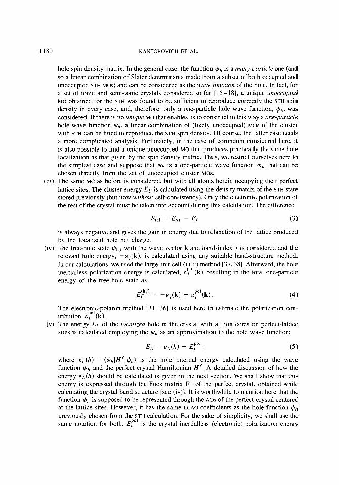
(iii) The same MC as before is considered, but with all atoms herein occupying their perfect lattice sites. The cluster energy EL is calculated using the density matrix of the STH state stored previously (but now without self-consistency). Only the electronic polarization of the rest of the crystal must be taken into account during this calculation. The difference
Ere1 = EST - EL ( 3 )
is always negative and gives the gain in energy due to relaxation of the lattice produced by the localized hole net charge.
(iv) The free-hole state & j with the wave vector k and band-index j is considered and the relevant hole energy, - .sj(k), is calculated using any suitable band-structure method. In our calculations, we used the large unit cell (LUC) method [37,38]. Afterward, the hole inertialless polarization energy is calculated, E:” (k), resulting in the total one-particle energy of the free-hole state as
The electronic-polaron method [31-361 is used here to estimate the polarization con- tribution .sYl(k).
(v) The energy EL of the localized hole in the crystal with all ion cores on perfect-lattice sites is calculated employing the $h as an approximation to the hole wave lunction:
where EL(^) = ($h I f f f l $ h ) is the hole internal energy calculated using the wave function $h and the perfect crystal Hamiltonian Hf. A detailed discussion of how the energy EL(^) should be calculated is given in the next section. We shall show that this energy is expressed through the Fock matrix Ff of the perfect crystal, obtained while calculating the crystal band structure [see (iv)]. It is worthwhile to mention here that the function $h is supposed to be represented through the AOS of the perfect crystal centered at the lattice sites. However, it has the same LCAO coefficients as the hole function $h
previously chosen from the STH calculation. For the sake of simplicity, we shall use the same notation for both. E;” is the crystal inertialless (electronic) polarization energy

HOLE SELF-TRAPPING IN SEMI-IONIC CRYSTALS 1181
resulting from the hole net charge. The difference
is usually positive and gives an estimate for the hole localization energy from the free state (kj) into the self-trapped state. Note that the difference EL(^) - (-Ej(k)) is definitely positive (due to the gain of the hole kinetic energy acquired in the state L), but the difference E F ’ - E$’(k) is not necessarily positive [I51 and its sign depends upon the particular material under consideration.
(vi) Lastly, the ST energy [Eq. (2)] is calculated as the sum of the two contributions obtained above [Eqs. (3) and (6)]. Since Erel < 0 and usually Eloc > 0, the net ST effect (the sign of AEsT) is not known a priori but must be obtained in careful calculations following the above given general scheme.
The method discussed here is represented schematically in Figure 1. Since the difference EST - EF cannot be calculated directly, we calculate it as the sum of two other differences, EF=L = Eloc and EL-ST = E,1. Both energies on the path F * L * ST could be calculated independently by means of any quantum chemical method that is suitable for each case. It is worthwhile mentioning here that the MH method can also be used for the path F * L [15- 181. However, from a practical point of view, it is more convenient to utilize the appropriate elements of the Fock matrix of the perfect crystal while constructing the corresponding MH [16,39] (see also the next section) rather than to calculate them from the band energies cj(k) as was done earlier [15,17, 181.
Therefore, the general idea of our method is to introduce an intermediate state L on the ST path F 3 ST considering this state L as the ST hole state in the unreluxed crystal. It gives us an opportunity to consider both states F and L using the perfect crystal Hamiltonian. At the same time, the states L and ST can be considered by means of any quantum chemical method using the same molecular cluster. It is believed that the energy differences EF-L and EL=,ST can be reproduced reliably by each of the methods used for the steps F =$ L and L * ST on the path.
The application of the method described above for the calculation of the ST energy in corundum is considered in Section 4. In the next section, we discuss the method of calculating the hole localization energy.
(k)
3. Calculation of the Hole Localization Energy
In this section, we discuss several important issues concerning the calculation of the localization energy of the hole. For the sake of simplicity, we ignore here the corresponding polarization correction that is applied separately [see Eqs. (3) and (4) above]. As is clear from the previous section, in order to calculate the localization energy of the hole, Eloc [Eq. (6)], the energy EL of the localized hole in the perfect crystal lattice has to be carefully calculated. The following estimate for the energy EL seems to have become generally accepted [25-271; namely, that the energy EL is assumed to coincide with the “center of gravity” of the band. Assuming again (as is usually done) that EL is the exact middle of the band, which is only true if the density of states is symmetrical about the middle of the band, we arrive at the Fowler conclusion that Eloc is the half the valence band width (a free-hole state [k,] is considered as lying at the bottom of the hole band). As was already mentioned earlier, in the majority of

1182 KANTOROVICH ET AL.
oxide crystals, this estimate appears to be too crude and leads to substantial overestimates of the localization energy due to the wide valence bands in these crystals.
Let us now consider the issue of how the energy EL should be calculated more thoroughly. The principal physical assumption allowing us to undertake the present derivation is that the localized hole can be described by some (possibly many-particle) wave function $ h , and, at the same time, the residual crystalline electronic orbitals can be equally considered as frozen in a form of perfect crystal orbitals. In the case of the one-particle spin-down hole state considered here, it means that $h is constructed from the perfect crystal Slater determinant, lo), by simply removing a one-electron state using the recipe:
where C k j l is the electron annihilation operator for the state (kjl), the fg) being appropriate coefficients.
Using the well-known expression for the perfect crystal Hamiltonian, Hf [27,35], it is easy to show without any additional approximations that the appropriate hole energy ~ ( h ) in the state $h is
&(h) = (@hlHfl@h) = ELF - ( b h l F f l b h ) > (8)
Q’
J ST
Figure 1. The hypothetical path of the hole self-trapping, as explained in the text. E is the total energy of the crystal, and Q , a generalized coordinate representing the positions of the crystal atoms. The following notations are used for different states of the hole: F , a free hole; L , a localized hole in the otherwise perfect crystal; ST, a stable self-trapped hole; and ST’, an unstable one. Qdef = Qval represents the coordinates of the atom(s) on which the hole is trapped, and Q’, the coordinates of the remaining atoms in the cluster. Thus, EF and EL include the inertialless polarization of the crystal.
HOLE SELF-TRAPPING IN SEMI-IONIC CRYSTALS 1183
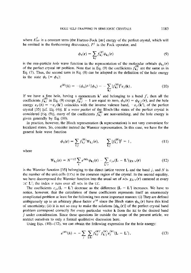
where ELF is a constant term (the Hartree-Fock [HF] energy of the perfect crystal, which will be omitted in the forthcoming discussion), F f is the Fock operator, and
k j
is the one-particle hole wave function in the representation of the molecular orbitals Gkj(r)
of the perfect crystal HF problem. Note that in Eq. (9) the coefficients f,$) are the same as in Eq. (7). Thus, the second term in Eq. (8) can be adopted as the definition of the hole energy in the state @h (= C$h):
k j
If we have a free hole, having a momentum k’ and belonging to a band j’, then all the coefficients fg) in Eq. (9) except fcj, = 1 are equal to zero, C$h(r) = $kljl(r), and the hole energy E F ( ~ ) = --&;/(k’) coincides with the inverse valence band, -Ej,(k’), of the perfect crystal [35] [cf. Eq. (4)]. If a wave packet of the Bloch-like states of the perfect crystal is considered [Eq. (9)], many of the coefficients f,$) are nonvanishing, and the hole energy is given generally by Eq. (10).
In practice, however, the Bloch representation (k-representation) is not very convenient for localized states. So, consider instead the Wannier representation. In this case, we have for the general hole wave function
where
is the Wannier function [35] belonging to the direct lattice vector L and the band j , and N is the number of the unit cells (UCS) in the common region of the crystal. In the second equality, we have decomposed the Wannier function into the usual set of AOS , y ~ / ~ ( r ) centered at every UC L’; the index Y runs over all AOS in the uc.
The coefficients cjP(L - L’) decrease as the difference IL - L’I increases. We have to notice, however, that the calculation of these coefficients represents itself an enormously complicated problem at least for the following two most important reasons: (i) They are defined ambiguously up to an arbitrary phase factor ei@ since the Bloch states $ k j ( r ) have this kind of uncertainty; (ii) it is not so easy to make the solutions {@k,(r)} of the perfect crystal band problem correspond correctly for every particular vector k from the BZ to the desired band j under consideration. Since these questions lie outside the scope of the present article, we restrict ourselves to only a formal qualitative discussion here.
Using Eqs. (10)-(12), we can obtain the following expression for the hole energy:
j LL’
1184 KANTOROVICH ET AL.
where
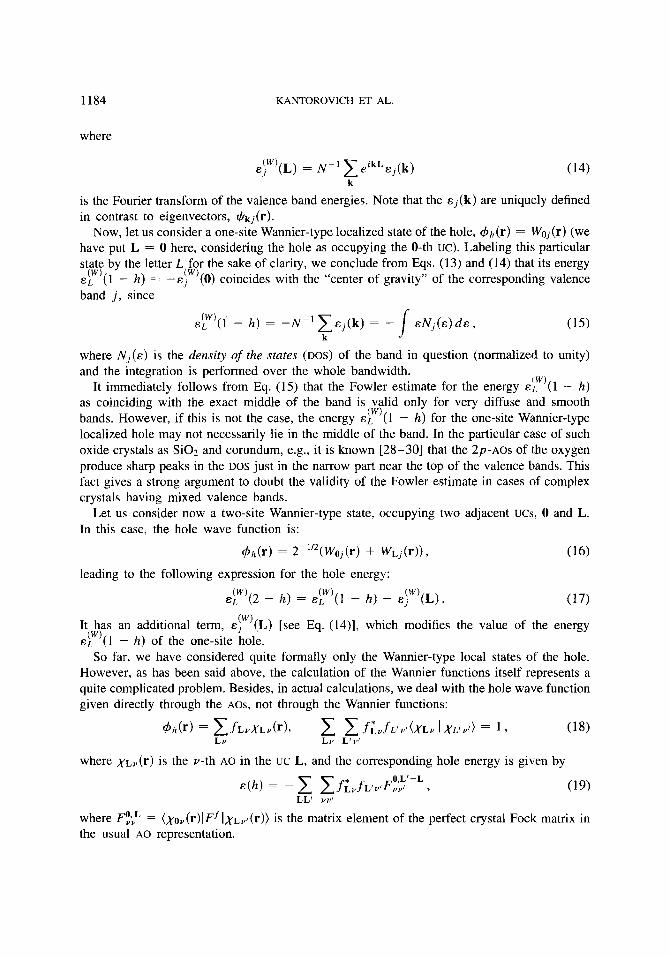
eIw’(L) = N-’ eikLe,(k) k
is the Fourier transform of the valence band energies. Note that the Ej(k) are uniquely defined in contrast to eigenvectors, J/kj(r).
Now, let us consider a one-site Wannier-type localized state of the hole, $h(r) = W,,(r) (we have put L = 0 here, considering the hole as occupying the 0-th UC). Labeling this particular state by the letter L for the sake of clarity, we conclude from Eqs. (13) and (14) that its energy e L ( 1 - h ) = - eiw’(0) coincides with the “center of gravity” of the corresponding valence band j , since
( W )
h ) = -N-‘ CEj(k) = - k
E N ~ ( E ) ~ E , (15) I where N , ( E ) is the density of the states (DOS) of the band in question (normalized to unity) and the integration is performed over the whole bandwidth.
It immediately follows from Eq. (15) that the Fowler estimate for the energy E/ , (1 - h ) as coinciding with the exact middle of the band is valid only for very diffuse and smooth bands. However, if this is not the case, the energy eL (1 - h) for the one-site Wannier-type localized hole may not necessarily lie in the middle of the band. In the particular case of such oxide crystals as SiOz and corundum, e.g., it is known [28-301 that the 2p-AOs of the oxygen produce sharp peaks in the DOS just in the narrow part near the top of the valence bands. This fact gives a strong argument to doubt the validity of the Fowler estimate in cases of complex crystals having mixed valence bands.
Let us consider now a two-site Wannier-type state, occupying two adjacent ucs, 0 and L. In this case, the hole wave function is:
1 W )
( W i
= 2 - ’ ’ 2 ( ~ ~ , ( r ) + W L ~ ( ~ ) ) ? (16) leading to the following expression for the hole energy:
(17) ( W ) ( W )
EL (2 - h) = E L ( 1 - h ) - &j”’(L).
It has an additional term, E(Iw’(L) [see Eq. (14)], which modifies the value of the energy eLw)(1 - h) of the one-site hole.
So far, we have considered quite formally only the Wannier-type local states of the hole. However, as has been said above, the calculation of the Wannier functions itself represents a quite complicated problem. Besides, in actual calculations, we deal with the hole wave function given directly through the AOS, not through the Wannier functions:
where ,yLV(r) is the v-th AO in the uc L, and the corresponding hole energy is given by
where FO,;” = (,yov(r)IFfIXLu/(r)) is the matrix element of the perfect crystal Fock matrix in the usual A 0 representation.
HOLE SELF-TRAPPING IN SEMI-TONIC CRYSTALS 1185
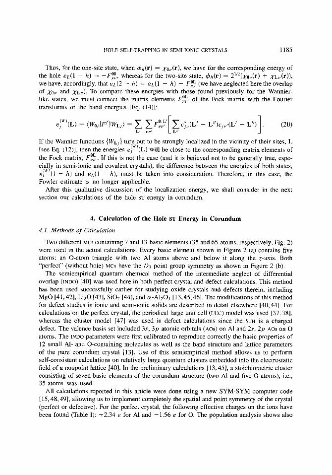
Thus, for the one-site state, when &(r) = ,yoY(r), we have for the corresponding energy of the hole ~ ~ ( 1 - h) = -FE, whereas for the two-site state, c$h(r) = 21’2(x~v(r) + ,yLY(r)), we have, accordingly, that E L (2 - h ) = E L ( 1 - h ) - F!f; (we have neglected here the overlap of ,yov and , y ~ ~ ) . To compare these energies with those found previously for the Wannier- like states, we must connect the matrix elements F::, of the Fock matrix with the Fourier transforms of the band energies [Eq. (14)]:
If the Wannier functions {WL]} turn out to be strongly localized in the vicinity of their sites, L [see Eq. (12)], then the energies e j (L) will be close to the corresponding matrix elements of the Fock matrix, F:;,. If this is not the case (and it is believed not to be generally true, espe- cially in semi-ionic and covalent crystals), the difference between the energies of both states, E L (1 - h ) and EL(^ - h) , must be taken into consideration. Therefore, in this case, the Fowler estimate is no longer applicable.
After this qualitative discussion of the localization energy, we shall consider in the next section our calculations of the hole ST energy in corundum.
( W )
( W )
4. Calculation of the Hole ST Energy in Corundum
4.1. Methods of Calculation
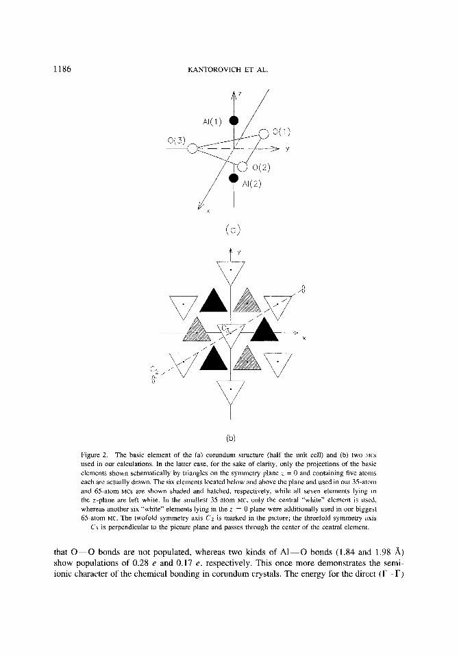
Two different MCS containing 7 and 13 basic elements (35 and 65 atoms, respectively, Fig. 2) were used in the actual calculations. Every basic element shown in Figure 2 (a) contains five atoms: an 0-atom triangle with two A1 atoms above and below it along the z-axis. Both “perfect” (without hole) MCS have the 0 3 point group symmetry as shown in Figure 2 (b).
The semiempirical quantum chemical method of the intermediate neglect of differential overlap (INDO) 1401 was used here in both perfect crystal and defect calculations. This method has been used successfully earlier for studying oxide crystals and defects therein, including MgO 141,421, Liz0 1431, Si02 [44], and a-A1203 [13,45,46]. The modifications of this method for defect studies in ionic and semi-ionic solids are described in detail elsewhere 140,441. For calculations on the perfect crystal, the periodical large unit cell (LUC) model was used [37,38], whereas the cluster model [47] was used in defect calculations since the STH is a charged defect. The valence basis set included 3s, 3p atomic orbitals (Am) on A1 and 2s, 2p AOS on 0 atoms. The INDO parameters were first calibrated to reproduce correctly the basic properties of 12 small Al- and 0-containing molecules as well as. the band structure and lattice parameters of the pure corundum crystal [13]. Use of this semiempirical method allows us to perform self-consistent calculations on relatively large quantum clusters embedded into the electrostatic field of a nonpoint lattice [40]. In the preliminary calculations [13,45], a stoichiometric cluster consisting of seven basic elements of the corundum structure (two A1 and five 0 atoms), i.e., 35 atoms was used.
All calculations reported in this article were done using a new SYM-SYM computer code [ 15,48,49], allowing us to implement completely the spatial and point symmetry of the crystal (perfect or defective). For the perfect crystal, the following effective charges on the ions have been found (Table I): +2.34 e for A1 and -1.56 e for 0. The population analysis shows also
1186 KANTOROVICH ET AL.
X
(b)
Figure 2. The basic element of the (a) corundum structure (half the unit cell) and (b) two M C ~
used in our calculations. In the latter case, for the sake of clarity, only the projections of the basic elements shown schematically by triangles on the symmetry plane z = 0 and containing five atoms each are actually drawn. The six elements located below and above the plane and used in our 35-atom and 65-atom MCS are shown shaded and hatched, respectively, while all seven elements lying in the z-plane are left white. In the smallest 35-atom MC, only the central “white” element is used, whereas another six “white” elements lying in the z = 0 plane were additionally used in our biggest 65-atom MC. The twofold symmetry axis C2 is marked in the picture; the threefold symmetry axis
C3 is perpendicular to the picture plane and passes through the center of the central element.
that 0-0 bonds are not populated, whereas two kinds of A1-0 bonds (1.84 and 1.98 A) show populations of 0.28 e and 0.17 e , respectively. This once more demonstrates the semi- ionic character of the chemical bonding in corundum crystals. The energy for the direct (T-T)
HOLE SELF-TRAPPING IN SEMI-IONIC CRYSTALS 1187
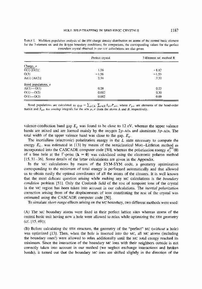
TABLE I. Mulliken population analysis of the STH charge density distribution on atoms of the central basic element for the 7-element MC and the B-type boundary conditions; for comparison, the corresponding values for the perfect
corundum crystal obtained in our LUC calculations are also given.
Perfect crystal 7-Element MC method B
Charge, e O(1) [0(2)1 - 1.56 -1.12 o(3) -1.56 - 1.53 AK1) [ A W I 2.34 2.32
Bond oooulations. e 0.28 0.002 0.002
0.23 0.30 0.00
Bond populations are calculated as ~ A B = EPLE* Z v E ~ S,,P,,, where P, , are elements of the bond-order matrix and S,, are overlap integrals for the AOS p, v from the atoms A and B , respectively.
valence-conduction band gap E, was found to be close to 12 eV, whereas the upper valence bands are mixed and are formed mainly by the oxygen 2p-AOs and aluminum 3p-AOs. The total width of the upper valence band was close to the gap, E,.
The inertialless (electronic) polarization energy in the L state necessary to compute the energy E L . was estimated in [13] by means of the semiclassical Mott-Littleton method as incorporated into the CASCADE computer code [50], whereas the polarization energy E T ’ ( O ) of a free hole at the r-point (k = 0) was calculated using the electronic polaron method [lS, 31-36]. Some details of the latter calculations are given in the Appendix.
In the MC calculations by means of the SYM-SYM code, a geometry optimization corresponding to the minimum of total energy is performed automatically and that allowed us to obtain easily the optimal coordinates of all the atoms of the clusters. It is well known that the most delicate question arising while making any MC calculations is the boundary condition problem [Sl]. Only the Coulomb field of the rest of nonpoint ions of the crystal in the MC region has been taken into account in our calculations. The inertial polarization correction arising from of the displacements of ions constituting the rest of the crystal was estimated using the CASCADE computer code [50].
To simulate short-range effects arising on the MC boundary, two different methods were used:
(A) The MC boundary atoms were fixed in their perfect lattice sites whereas atoms of the central basic unit having now a hole were allowed to relax while optimizing the STH geometry (cf. [15,49]);
(B) Before calculating the STH structure, the geometry of the “perfect” MC (without a hole) was optimized 1131. Then, when the hole is inserted into the MC, all MC atoms (including the boundary ones!) were allowed to relax additionally until the MC total energy reached its minimum. Since the interaction of the boundary MC ions with their neighbors outside is not correctly taken into account in our method (we neglect exchange interactions and broken bonds), it turned out that the boundary MC ions are shifted slightly in the direction of the
1188 KANTOROVICH ET AL.
MC center. It is believed that these displacements of the ions of the “perfect” MC are able to compensate for the incorrect boundary conditions and that they create some perturbation equivalent to that arising from the missed interactions with the outside region.
We shall return to the discussion of the boundary conditions in Section 6 while considering the results of our calculations. In the following two subsections, method A will be considered, whereas method B is considered in Subsection 4.4.
4.2. Determination of the STH State: Method A
To check the validity of the boundary conditions of type A (see the end of Section 2), we have fixed the positions of all atoms of the basic elements surrounding the central element in the “perfect” MCS and optimized the geometry of the atoms of the central fragments only. The atomic displacements found are quite small (about 0.2% of the atom-atom distance for the 7-basic-element MC and near 0.1% for the 13-basic-elements one), thus confirming the adequacy of those boundary conditions at least for the geometry optimization (cf. [ 491).
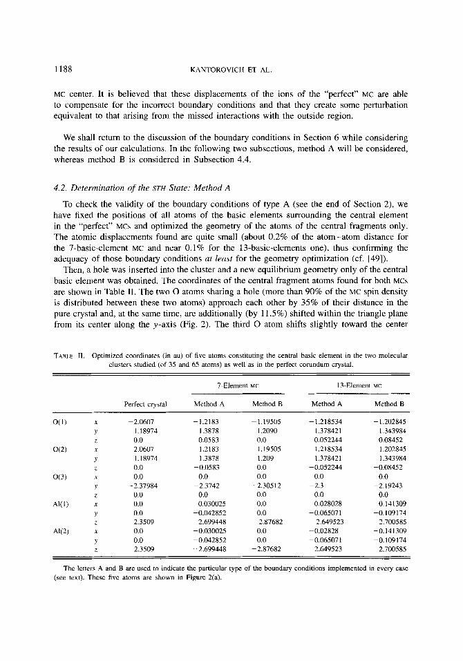
Then, a hole was inserted into the cluster and a new equilibrium geometry only of the central basic element was obtained. The coordinates of the central fragment atoms found for both MCs are shown in Table 11. The two 0 atoms sharing a hole (more than 90% of the MC spin density is distributed between these two atoms) approach each other by 35% of their distance in the pure crystal and, at the same time, are additionally (by 11.5%) shifted within the triangle plane from its center along the y-axis (Fig. 2 ) . The third 0 atom shifts slightly toward the center
TABLE 11. Optimized coordinates (in au) of five atoms constituting the central basic element in the two molecular clusters studied (of 35 and 65 atoms) as well as in the perfect corundum crystal.
7-Element MC 13-EIemen1 MC
Perfect crystal Method A Method B Method A Method B
O(1) X -2.0607 -1.2183 - 1.19505 - 1.218534 - 1.202845 Y 1.18974 1.3878 1.2090 1.378421 1.343984 Z 0.0 0.0583 0.0 0.052244 0.08452
4’ 1.18974 1.3878 1.209 1.378421 1.343984 Z 0.0 -0.0583 0.0 - 0.052244 -0.08452
o(3) X 0.0 0.0 0.0 0.0 0.0 Y -2.37984 -2.3742 -2.30512 -2.3 -2.19243 2 0.0 0.0 0.0 0.0 0.0
0.141 309 Y 0.0 -0.042852 0.0 -0.065071 -0. I09 I74 Z 2.3509 2.699448 2.87682 2.649523 2.700585
AK2) X 0.0 -0.030025 0.0 -0.02828 -0.141 309 Y 0.0 -0.042852 0.0 -0.065071 -0.1091 74 2 -2.3509 -2.699448 -2.87682 -2.649523 -2.700585
om X 2.0607 1.2183 1.19505 1.218534 1.202845
X AK1) 0.0 0.030025 0.0 0.028028
The letters A and B are used to indicate the particular type of the boundary conditions implemented in every case (see text). These five atoms are shown in Figure 2(a).
HOLE SELF-TRAPPING IN SEMI-IONIC CRYSTALS 1189
of the triangle (by nearly 8% of the distance to the center in the perfect basic element). In addition, the two A1 atoms are displaced symmetrically from the triangle plane (by 11%) and slightly from the z-axis.
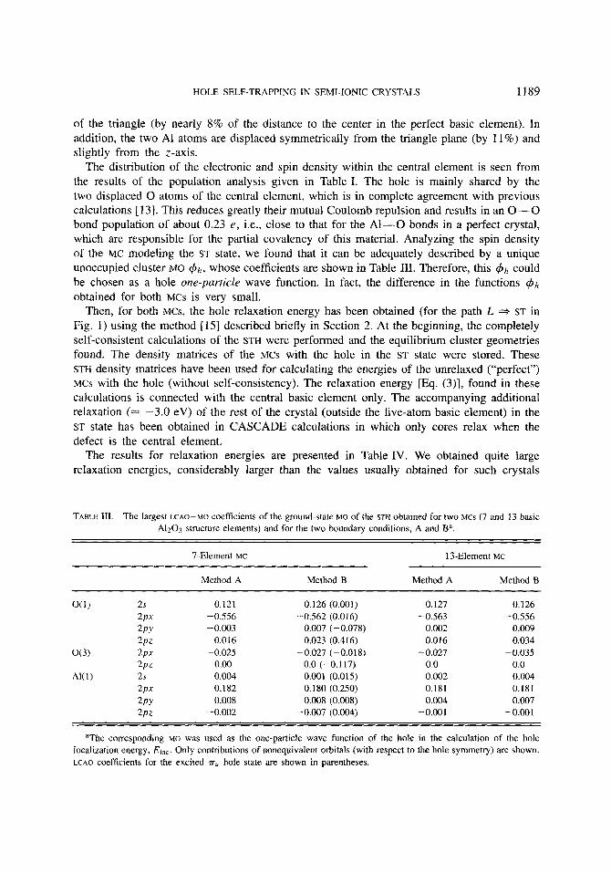
The distribution of the electronic and spin density within the central element is seen from the results of the population analysis given in Table I. The hole is mainly shared by the two displaced 0 atoms of the central element, which is in complete agreement with previous calculations [13]. This reduces greatly their mutual Coulomb repulsion and results in an 0-0 bond population of about 0.23 e , i.e., close to that for the A1-0 bonds in a perfect crystal, which are responsible for the partial covalency of this material. Analyzing the spin density of the MC modeling the ST state, we found that it can be adequately described by a unique unoccupied cluster MO $ h , whose coefficients are shown in Table 111. Therefore, this $h could be chosen as a hole one-particle wave function. In fact, the difference in the functions $Ih
obtained for both MCs is very small. ST in
Fig. 1) using the method [15] described briefly in Section 2. At the beginning, the completely self-consistent calculations of the STH were performed and the equilibrium cluster geometries found. The density matrices of the MCS with the hole in the ST state were stored. These STH density matrices have been used for calculating the energies of the unrelaxed (“perfect”) MCS with the hole (without self-consistency). The relaxation energy [Eq. (3)], found in these calculations is connected with the central basic element only. The accompanying additional relaxation (2 -3.0 eV) of the rest of the crystal (outside the five-atom basic element) in the ST state has been obtained in CASCADE calculations in which only cores relax when the defect is the central element.
The results for relaxation energies are presented in Table IV. We obtained quite large relaxation energies, considerably larger than the values usually obtained for such crystals
Then, for both MCS, the hole relaxation energy has been obtained (for the path L
TABLE 111. The largest LCAO-MO coefficients of the ground-state MO of the STH obtained for two MCS (7 and 13 basic A1203 structure elements) and for the two boundary conditions, A and Ba.
7-Element MC 13-Element MC
Method A Method B Method A Method B
O(1) 2s 0.121 0. I26 (0,001) 0.127 0.126 2PX -0.556 -0.562 (0.016) -0.563 -0.556 2PY -0.003 0.007 (-0.078) 0.002 0.009 2PZ 0.016 0.023 (0.416) 0.016 0.034
o(3) 2PX -0.025 -0.027 (-0.018) -0.027 -0.035
AK 1) 2s 0.004 0.001 (0.015) 0.002 0.004
2PY 0.008 0.008 (0.008) 0.004 0.007
2PZ 0.00 0.0 (-0,117) 0.0 0.0
2PX 0.182 0.180 (0.250) 0.181 0.181
2PZ -0.002 -0.007 (0.004) -0.001 -0.001
aThe corresponding MO was used as the one-particle wave function of the hole in the calculation of the hole localization energy, Eloc. Only contributions of nonequivalent orbitals (with respect to the hole symmetry) are shown. LCAO coefficients for the excited rU hole state are shown in parentheses.

1190 KANTOROVICH ET AL.
as alkali halides [15]. Note that we can reasonably neglect the electronic polarization when calculating the relaxation energy, since in both states (L and ST), practically the same electronic density distributions were chosen.
4.3. Calculation of the ST Energy: Method A
Using the hole wave function 4 h [Eq. (18)], found for the fully relaxed ST state (see above), the hole localization energy El,,, [Eq. (6)] was calculated ( F * L path in Fig. 1). The energy .sL(h) of the localized hole corresponding to the point L has been calculated using Eq. (19). Appropriate matrix elements of the Fock matrix for the perfect corundum crystal have been obtained by means of the LUC method with the same set of parameters [13]. A comparatively large LUC [A140618 (Le., 80 atoms) has been used for these calculations, providing us with a good enough estimate of the needed elements of the Fock matrix.
For both MCS, the results are similar and are given in Table IV. The “pure” localization energy, E (h ) + Ej(k = 0) [Eqs. (4) and (5)] [without the electronic “repolarization” contribu- tion, @ O f - eyo’(k = O ) ] is found to range between 0.31 and 0.75 eV depending on the MC and the hole wave function 4 h chosen. We have used two kinds of wave function for the latter: the full $h (as in Table 111) spread over the whole central element and obtained in the STH calculations and a simplified + h distributed equally over the two 0 atoms only.
Then, the inertialless polarization energy of a free hole (point F in Fig. 1) at the top of the upper valence band (T-point) was found to be e,P”’(O) = -3.12 eV. The corresponding method based on the electronic polaron model [15] as well as the parameters used in the calculations are described in the Appendix in greater detail. The inertialless polarization energy in the localized state of the unrelaxed crystal (point L ) was estimated to be Erl = -2.0 eV in earlier CASCADE calculations [13]. Thus, the repolarization energy in the stage F * L turns out to be 1.12 eV and positive.
All these findings allow us to calculate finally the hole ST energy. Results are given in Table IV. We obtained quite large negative values for the hole ST energies for both MCs studied for type A boundary conditions.
TABLE IV. Different contributions to the hole ST energy (in eV) for the two MCS studied (containing 35 and 65 atoms, respectively) and for the two kinds of boundary conditions, A and B, used.
7-Element MC 13-Element MC
Method A Method B Method A Method B ~ ~ ~ ~ ~
Ere1 a -9.8 -5.5 -9.2 -5.5 Elocb 0.37 (0.74) 0.49 (0.74) 0.48 (0.74) 0.45 (0.75) Eloc‘ 0.22 (0.59) 0.34 (0.59) 0.33 (0.59) 0.30 (0.6) AEST -12.58 (-12.21) -8.16 (-7.91) -11.87 (-11.61) -8.0 (-7.7)
Energies in parentheses correspond to the case when the hole wave function, &(r), is equally shared by the two
aWithout the inertial polarization energy around the central basic element (= -3.0 eV). bWithout the repolarization energy (see text). ‘With the incorporation of the repolarization energy.
oxygen atoms O(1) and O(2) only, shown in Figure 1.
HOLE SELF-TRAPPING IN SEMI-IONIC CRYSTALS 1191
4.4. Calculation of the SC Energy: Method B
Let us consider now results of another set of calculations in which all atoms of the MCS were allowed to relax (B-type boundary conditions). In this case for both MCS under study, the large amount of the MC relaxation energies have been obtained already at the stage of the “perfect” MCs relaxation (without a hole). For example, for the 13-element MC, the “perfect” cluster relaxation energy is about - 15 eV. As a result, the additional relaxation arising after the hole is inserted is -5.3 eV only, i.e., a much smaller value than that obtained above in the case A (see Table IV). Besides, we obtained slightly different results for atomic displacements and the hole wave function +h, listed in the Tables I and 111, respectively. Corresponding localization and ST energies were calculated in the same way as described above and are given in Table IV.
5. Calculation of the Hole Absorption Energy
As was said above, the wave function of the ground state of the STH in corundum, +h ,
is formed mainly by two inward relaxed 0 atoms responsible for a strong covalent g -
bonding-quite similar to that well known for the STHS in alkali halides (VK-centers) [27]. The contribution of the two A1 atoms lying symmetrically below and above the oxygen triangle is less than 10%.
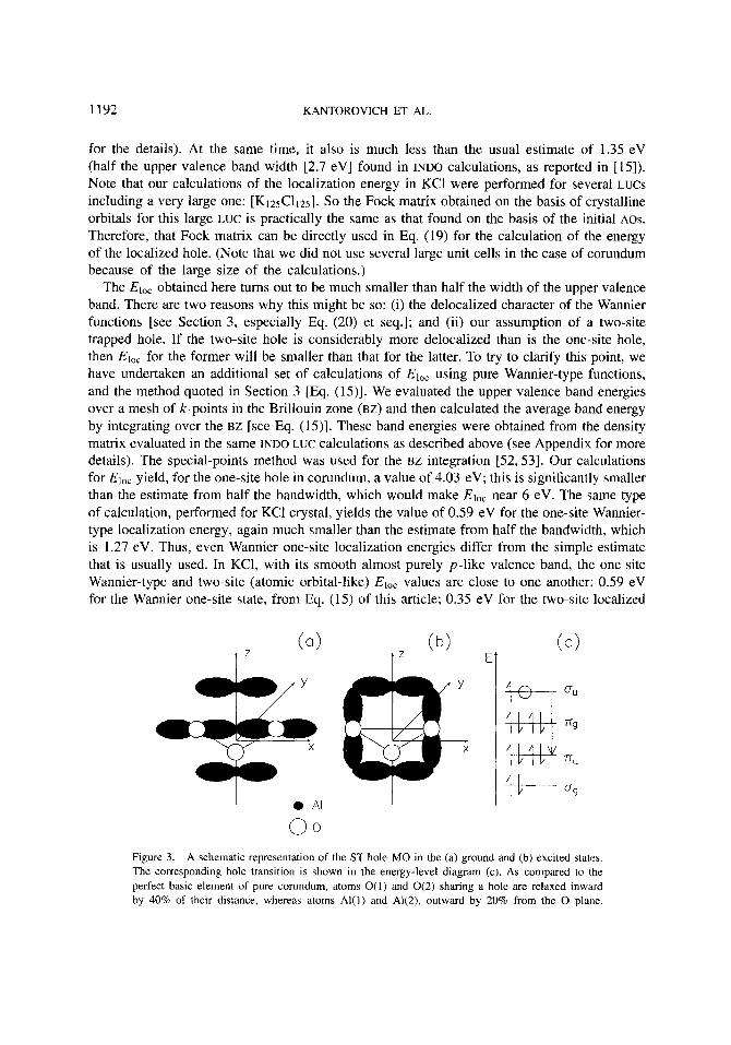
Using the 7-element MC, an excited state of the STH was studied using the ASCF method (i.e., the excited state has been obtained in the following way: We take an electron from one of occupied states of the cluster and put it to an unoccupied one while preparing the density matrix for the initial guess; then, a complete HF self-consistent solution is obtained). We found that the hole wave function 4; in the excited state consists mainly of 2pz-oxygen AOs strongly overlapping with 3s, 3 p AOS of A1 as is shown in Table I11 and Figure 3. Their contribution into the 4; orbital increases by a factor of 18, compared with the ground-state wave function +A. It is more delocalized now over the third 0 atom of the 0 triangle and the two A1 atoms above and below this 0 plane. The relevant absorption energy [shown by an arrow in Fig. 3(c)] is predicted to be around 3 eV, which is close to that of the absorption bands observed experimentally for the defect-induced hole centers in corundum [ 121.
6. Discussion and Conclusions
The results of our quantum chemical calculations by the INDO method have demonstrated that it is a powerful tool for predicting the geometry and the energetics of carrier ST even in materials with mixed valence bands and with a complicated structure, like the corundum crystal with 10 atoms per unit cell. Our theoretical analysis confirms the interpretation of experimental data [ 10,111 arguing for the existence of ST holes in corundum crystals. The somewhat surprising conclusion has also been drawn that the “pure” contribution to the hole localization energy Eloc (without the polarization term) in crystals with mixed bands can turn out to be much less than 0.3-0.5 of the width of the upper valence band, as was found earlier for purely ionic solids [15, 17,181. This is an additional factor favoring hole ST in oxide crystals with wide valence bands, but well-pronounced narrow oxygen subbands near the top of the valence band.
For comparison, use of the same procedure for the KCl (ionic) crystal yields for the “pure” part of the localization energy the value 0.35 eV. This is close to the value of 0.47 eV found in [I51 using another MH (the latter was fitted directly to a set of band energies, see [I51
1192 KANTOKOVICH ET AL.
for the details). At the same time, it also is much less than the usual estimate of 1.35 eV (half the upper valence band width [2.7 eV] found in INDO calculations, as reported in [15]). Note that our calculations of the localization energy in KCl were performed for several LUCS including a very large one: [K125C1125]. So the Fock matrix obtained on the basis of crystalline orbitals for this large LUC is practically the same as that found on the basis of the initial AOS.
Therefore, that Fock matrix can be directly used in Eq. (19) for the calculation of the energy of the localized hole. (Note that we did not use several large unit cells in the case of corundum because of the large size of the calculations.)
The Eloc obtained here turns out to be much smaller than half the width of the upper valence band. There are two reasons why this might be so: (i) the delocalized character of the Wannier functions [see Section 3, especially Eq. (20) et seq.]; and (ii) our assumption of a two-site trapped hole. If the two-site hole is considerably more delocalized than is the one-site hole, then Eloc for the former will be smaller than that for the latter. To try to clarify this point, we have undertaken an additional set of calculations of Eloc using pure Wannier-type functions, and the method quoted in Section 3 [Eq. (15)]. We evaluated the upper valence band energies over a mesh of k-points in the Brillouin zone (BZ) and then calculated the average band energy by integrating over the BZ [see Eq. (15)]. These band energies were obtained from the density matrix evaluated in the same INDO LUC calculations as described above (see Appendix for more details). The special-points method was used for the BZ integration [52,53]. Our calculations for Eloc yield, for the one-site hole in corundum, a value of 4.03 eV; this is significantly smaller than the estimate from half the bandwidth, which would make Eloc near 6 eV. The same type of calculation, performed for KCl crystal, yields the value of 0.59 eV for the one-site Wannier- type localization energy, again much smaller than the estimate from half the bandwidth, which is 1.27 eV. Thus, even Wannier one-site localization energies differ from the simple estimate that is usually used. In KC1, with its smooth almost purely p-like valence band, the one-site Wannier-type and two-site (atomic orbital-like) Eloc values are close to one another: 0.59 eV for the Wannier one-site state, from Eq. (15) of this article; 0.35 eV for the two-site localized
Figure 3. A schematic representation of the ST hole MO in the (a) ground and (b) excited states. The corresponding hole transition is shown in the energy-level diagram (c). As compared to the perfect basic element of pure corundum, atoms O(1) and O(2) sharing a hole are relaxed inward by 40% of their distance, whereas atoms Al(1) and A1(2), outward by 20% from the 0 plane.
HOLE SELF-TRAPPING IN SEMI-IONIC CRYSTALS 1193
state, from Eq. (19) of this article; and 0.47 eV for the two-site state from the MH method [47]. But, apparently, this is not the case in corundum, which has a much more complicated valence band structure. Nevertheless, in both materials, the localization energy Eloc even for the hole trapped on one site is considerably less than half the bandwidth. Our calculations therefore predict that ST holes in corundum will indeed be stable.
Apart from the usual approximations made in our quantum chemical study (semiempirical INDO method, the MC approach with not quite perfect boundary conditions, limited basis set, etc.), there are some important points that relate directly to the simulation of the intermediate state L on the path F * L =+ ST (Fig. 1). We shall now discuss these in more detail.
In calculating the energy ofthe MC at the L point [energy EL, see Eq. (3)], the first-order reduced density matrix for the spin a (up and down),
found previously for the STH must be used, where { x P ( r ) } are the AOs centered on the displaced afornic positions in the MC. However, in real calculations of the MC energy EL at the point L , the bond-order matrix P" = llPzPl 11 is used only, but the atomic orbitals, xf(r), are centered at the lattice sites (which is indicated by the superscript f):
It might seem that this contradiction results in an additional error, especially if the displacements of the ions in the defect region are large. (It gives the correct charge in the defect region, but incorrect dipole and higher moments there.) However, this is not the case because the only thing that we must take care of is the one-to-one correspondence between density matrices used during the calculations of the hole energy at the L point. Indeed, while calculating the energy .sL(h) [see Eq. (5)] of the hole in the same state L but using the perfect-crystal Fock matrix [Eq. (18)], all AOs are centered at the lattice sites as well.
However, in calculating the energy EL(h), all crystal orbitals except +h were assumed frozen. This is actually an approximation and it corresponds to the following components of the reduced density matrix when the localized hole occupies a spin down state:
where pf(r,r') is the corresponding density matrix of the perfect crystal, and +h(r), the hole one-particle wave function. Of course, this simplified (reduced) density matrix is not the same as that given by Eq. (22), and this discrepancy leads to some error in the calculated localization energy, Eloc.
To avoid this approximation, the same density [Eq. (23)], would have to be used in the calculation of the MC energy EL at the point L. However, quite large LUCS are necessary to obtain the bond-order matrix Pf = I ~ P E L , , 11 of the perfect crystal on all atoms of the MC. Indeed, it is known [37,40] that only such elements P E ) of the bond-order matrix are reproduced
1194 KANTOROVICH ET AL.
correctly in the LUC method that refer to the direct lattice vectors L provided that ILI is less than half the LUC length. Therefore, these calculations were not done because of the large MCS
used in the present study. We plan to check the magnitude of the error introduced in this way in the nearest future.
A comparison of the two kinds of the boundary conditions imposed on the quantum clusters shows clearly that a reasonable relaxation energy of several eV for a crystal with a defect (hole) is obtained only in method B where all atoms of the “perfect” cluster are allowed first to relax to their equilibrium geometry, thus simulating the boundary effects of the broken bonds and neglected exchange interaction in semi-ionic solids. This conclusion would seem a little bit unexpected from the viewpoint of the limit achieved as the MC increases infinitely, thus simulating a crystal, when method A is expected to be preferable and should display a better convergence. Nevertheless, our results show clearly that the sizes of the MCS (up to 65 atoms) used in the present calculations are insuficient to achieve this convergence and thus make reliable predictions of the relaxation energies using type A boundary conditions. Indeed, detailed investigations of the VK-center relaxation energies made in [49] for the KC1 crystal show that actually very large MCS containing hundreds of atoms are needed to approach the infinite-crystal limiting value for such a crystal, even if the polarization energy is included properly. Therefore, substantially larger MCS should be used in the case of corundum. which is a partly covalent crystal. However, these calculations appear to be very time-consuming and expensive because of the large number of atoms in the unit cell in corundum.
Despite the fact that our calculations support arguments in favor of the existence of small polarons in corundum, as deduced from experimental studies [ 10,111, additional experimental and theoretical investigations are necessary to conclude whether the one-site or two-site polaron is energetically more favorable. Of the available experimental methods, Raman spectroscopy appears to be the most promising. An excellent example is provided by recent studies of the structure of self-trapped excitons in alkali halides [54]. Of the possible theoretical approaches, careful ah initio studies are necessary in order to check whether the INDO semi-empirical method used here overestimates the chemical bonding in the 0;- molecular polaron suggested by us. Indeed, electron correlation (which is basically neglected at the INDO level) is known to make a considerable contribution to bonding in a free oxygen molecule [55 ] , but whether this is also true for our 0;- is not clear at present. The fact that our calculations show preference for the molecular (two-site) polaron (see also [46]) does not contradict the experimental observation of a one-site hole trapped by an A1 vacancy or a Mg impurity [56]. In these cases, the hole is localized by the Coulomb field of the defect and the whole energy balance has therefore to be revised. Recently [57], semiempirical and ab initio molecular orbital calculations have demonstrated the stability of the STH in a-SiO2, which is another semi-ionic oxide. In this material, the calculations predict strong localization of the hole on one oxygen atom. It is quite possible that both forms of small polaron coexist in corundum, the two stable states being separated by an energy barrier. We plan to investigate this and to estimate the height of this barrier in the next paper.
Acknowledgments
The authors would like to express their gratitude to A.L. Shluger and E.N. Heifets for their interest in this work and to A.I. Livshicz for useful discussions and computational
HOLE SELF-TRAPPING IN SEMI-IONIC CRYSTALS 1195
assistance. Financial support provided by the Direccion General de Investigacion Cientifica y Technica of the Ministerio de Educacion y Ciencia (Spain) under Grant SAB92-0226 is also gratefully acknowledged by L. K.; A. S. and E. K. thank the International Science Foundation for financial support.
Appendix
The inertialless polarization energy of a free hole in the band j and with a wave vector k = 0 (the top of the upper valence band of corundum) is calculated using arguments based on the electronic-polaron model [15]:
where
ljjf(q> = (OjIe’q’Iqj’) = x uj*,(o)J,,f(q)ujiCLi(q)
Jfip!(q) = (OpIeiqrIqp’) = ~e-’qL(Xofi le iqrIXLCL,) .
(A.3) Pfi’
and
(A.4) L
Here, ,yLP(r) is the Slater-type A 0 located in the L-th unit cell (UC), L being the relevant lattice vector; the vector q runs over the whole Brillouin zone (BZ), j ’ runs over all valence bands, and is the high-frequency dielectric constant; uc, the uc volume, E,, the band gap; and N , the number of ucs in the crystal. Lastly, Ej(q) and Uj(q) = IlUj,(q)ll are the eigenvalues and the eigenvectors of the Fock matrix of the perfect crystal, i.e., crystal orbitals $kj(r) are expressed over the crystalline basis orbitals (lattice sums)
(A.5a)
in the following way:
$kJ(r) = h j ) = 1 u,p(q)lqp). (ASbj
The eigenvalues and eigenvectors have been taken from the perfect crystal LUC calculations done by means of the SYM-SYM package. It permits us to calculate post factum both values of c,(q) and U,(q) for any q E BZ using the LUC density matrix (see, e.g., [%I).
The integration over the BZ (i.e., q) in Eq. (A.l) is performed using the special-points method [52] ; in addition, the singularity l / q 2 (when q approaches the BZ center, q 3 0) is avoided using the method suggested in [59]. Thus, instead of Eq. (A.l), we get
P
1196 KANTOROVICH ET AL.
where G = { g } is the point group of a crystal, IGI = dim(G), (qh, W A ) represent the set of special points qA with the corresponding weights W A , and y is a parameter allowing us to avoid the singularity at q = 0 [59].
Using the point symmetry of the crystal, it is possible to simplify considerably the calculation of the eip"'(0). Indeed, let us consider the factor Fj(gq) for any symmetry operation g E G. First of all, we notice that only special points lying inside the BZ need be chosen. This means that the vector gq never lies on the BZ surface and, thus, additional problems can be avoided. Then, we have E,(gq) = ej(q) and
Uj(gq) = Q(q)(g)Uj(qI> if Sq # 9 (A.7a)
Uj(gq) = Uj(q), if Sq = 9 , (A.7b)
where @(q)(g) represents the corresponding rotational unitary matrix for the crystal basis orbitals Iqp) [Eq. (ASa)]. It is given by
Q,/,(q) (8) = Q/lIp(g)ei(~q'L(f i~g)) , (A&
where L ( p , g ) = (g 1 T~)& - RCLg is a direct lattice translation, rg being the fractional translation of the crystal space group corresponding to the rotation g, whereas R, is the radius-vector of the A 0 ,yop in the 0-th uC. Lastly,
@,&) = D:L(dS(l, 1W(RpG R/1J 64.9)
is the rotational matrix for the AOS {,yoCL(r)}, where 1, m are their angular quantum numbers, D(')(g) is the rotational matrix for the real spherical functions [60], and S is the Kroneker delta symbol. Besides, R,U = Rpp is the radius-vector of the orbital I,yop/,) in the 0-th uc obtained after the symmetry operation (g I T ~ ) is applied to the vector R, and a proper direct lattice translation L(p, g ) is applied to return it back to the 0-th uC. Note that for symmorphic crystals the property ps = p is always valid, whereas for nonsymmorphic crystals, an atom R p g is equivalent to the atom R, (they are of the same chemical type), but pug may not be equal to p (i.e., the AOS may not be located on the same atom).
By the way, the following identities are proved for the crystal MOS Iqj) [Eq. (ASb)] expanded over the basis orbitals Iqp) [Eq. (ASa)] by means of the coefficients Uj,(q) (cf. [61]):
i lqj) = ISq,j) if f q , (A.lOa)
Slqj) = 2 A:;(g)lqj), if s q = 9 , (A. lob) i'
where
A$i(g) = Uj/(q)+@(q)(g)Uj(q). (A.lOc)
Note that these formulas should be additionally modified if the q-vector lies on the BZ surjiuce. Lastly, the following identity can be proved for the integrals J,,>(q) in Eq. (A.4) if the
above-discussed rotational properties of the crystalline basis orbitals Iqp) are used:
J(g-'q) = e-iqT8@(o)(g)+ J(q)@(d(g-')+ . (A. 11)
Substituting Eqs. (A.7) and (A. 11) into Eq. (A.4), we get the final expression for the Zj,,(g-'qA) containing both the integrals J(qA) and the eigenvectors U,(qA) taken only at the point qA for
HOLE SELF-TRAPPING IN SEMI-IONIC CRYSTALS 1197
any g E G and (likely) some additional factors in the form of products of the rotation matrices @(qA)(g). Note also that Eq. (A.6) can be further simplified by substituting for G the set of generators g a of the right coset decomposition of the group G over the local group H of the wave vector qA (G = U,g,H), and, correspondingly, lGl/lHl appears instead of IGl in Eq. (A.6).
We have calculated the polarization energies E Y ' ( O ) for a number of the upper valence bands of corundum, using coo = 3.1 [62] and E , = 12 eV from our LUC calculations. It turns out that the value y = 1.8(c2 + 2 ~ ~ ) " ~ (a and c are the usual parameters of the trigonal corundum lattice) guarantees the complete avoidance of the above-mentioned l/q2-singularity, since small variations of y do not affect the total polarization energy. The plane-wave integrals in Eq. (AS) were calculated by expanding Slater-type orbitals over the Gaussian-type orbitals [63]. Three terms in the decomposition turned out to be sufficient in order to get an acceptable precision (= 0.01 eV). The Monkhorst-Pack (MP) method [53] has been used to generate the special points sets, and a value of 4 for the MP parameter appeared to give already satisfactory results for the energy.
Bibliography
[I] J. M. Vail, J . Phys. Chem. Solids 51, 589 (1990). [2] M. N. Kabler, Point Defects in Solids (Plenum, New York, 1972), p. 327. [3] D. Shoemaker, Phys. Rev. B 7, 786 (1973). [4] D. Shoemaker and F. Waldner, Helv. Phys. Acta 44, 560 (1971). [5] M. Islam, Philos. Mag. A 64, 1119 (1991). [6] J.-M. Spaeth and F.K. Koschick, J . Phys. Chem. Solids 52, 1 (1991). [7] D.L. Griscom, Phys. Rev. B 40, 4224 (1989). [8] W. Unzig, Phys. Rev. 99, 1890 (1955). [9] I. Tale and A. Gailitis, Bull. Sov. Acad. Sci. 35, 1336 (1971).
[lo] E. A. Kotomin, I. Tale, V. Tale, P. Butlers, and P. Kulis, J . Phys.: Cond. Matter 1, 6777 (1989), [ I I] P. Kulis, Z . Rachko, M. Springis, I . Tale, and J. Janson, Radiat. Eff. Defects Solids 119-121, 963 (1991). [I21 J. Valbis and N. Itoh, Radiat. Eff. Defects Solids 116, 171 (1991). [I31 P. W.M. Jacobs, E.A. Kotomin, A. Stashans, E. Stefanovich, and I . Tale, J . Phys.: Cond. Matter 4, 7531 (1992). [I41 Y. Toyozawa, in Excitonic Processes in Solids, M. Ueta, H. Kanzaki, K. Kobayashi, Y. Toyozawa, and E.
11.51 L. Kantorovich, E. Heifets, A. Livshicz, M. Kuklja, and P. Zapol, Phys. Rev. B 47, 14875 (1993). [I61 E. Heifets and A. Shluger, J. Phys.: Cond. Matter 4, 831 1 (1992). [I71 A. Shluger, L. Kantorovich, E. Heifets, E. Shidlovskaya, and R. Grimes, J. Phys.: Cond. Matter 4, 7417 (1992). [I81 A. L. Shluger, E. N. Heifets, J. D. Gale, and C. R. A. Catlow, J. Phys.: Cond. Matter 4, 571 1 (1992). [I91 Y. Toyozawa, Progr. Theor. Phys. 26, 29 (1961). [20] A.L. Shluger and A.M. Stoneham, J. Phys.: Cond. Matter 5, 3049 (1993). [21] T. Higashimura, Y. Nakaoka, and T. Iida, J. Phys. C: Solid State Phys. 17, 4127 (1984). [22] Y. Nakaoka, Phys. Stat. Sol. (b) 127, 327 (1985). [23] T. Iida and R. Monnier, Phys. Stat. Sol. (b) 74, 91 (1976). [24] W. Hayes and A.M. Stoneham, Defects and Defect Process in Non-Metallic Solids (Wiley, New York, 1985). [25] T. L. Gilbert, Lecture Notes for the NATO Summer School (Ghent, 1966). [26] W. B. Fowler, Physics of Colour Centers (Academic Press, New York, 1968), Chap. 2. [27] A.M. Stoneham, Theory of Defects in Solids (Oxford University Press, London, 1975), Chap. 18. [28] M. Causa, R. Dovesi, C. Roetti, A. Kotomin, and V. Saunders, Chem Phys. Lett. 140, 120 (1987). [29] L. Salasco, R. Dovesi, R. Orlando, M. Causa, and V. Saunders, Mol. Phys. 72, 267 (1991). [30] Y.-N. Xu and W.Y. Ching, Phys. Rev. B 43, 4461 (1991). [31] S. Wang, C. K. Mahutte, and M. Matsuura, Phys. Stat. Sol. (b) 51, 1 1 (1972).
Hanamura, Eds. (Berlin, Heidelberg, New York, Springer-Verlag, 1986).
1198 KANTOROVICH ET AL.
[32] A.B. Kunz, Phys. Rev. B 6, 606 (1972). [33] A.B, Kunz and D. J. Mickish, Phys. Rev. B 8, 779 (1973). [34] S.T. Pantelides, D. J. Mickish, and A. B. Kunz, Phys, Rev. B 10, 5203 (1974). [35] E. Haken, in Polarons and Excitons, C. G. Kuper and G. D. Whitfield, Eds. (1963); E. Haken, Quantenfeld-theorie
[36] L.N. Kantorovich, Izv. Acad. Nauk Latv SSR N5, 18 (1987). [37] R. A. Evarestov, Quantum-Chemical Methods in Solid State Theory (Leningrad State University, Leningrad, 1982) [38] R. A. Evarestov and V. A. Lovchikov, Phys. Stat. Sol. (b) 93, 469 (1979); h i d . 97, 743 (1979). [39] L.N. Kantorovich and P.B. Zapol, Phys. Stat. Sol. (b) 1994, in press. [40] E. Stefanovich, E. Shidlovskaya, A. Shluger, and M. Zaharov, Phys. Stat. Sol. (b) 160, 529 (1990). [41] A.L. Shluger, R. W. Grimes, C.R.A. Catlow, and N. Itoh, J . Phys.: Cond. Matter 3, 8027 (1991). 1421 A. L. Shluger, E. A. Kotomin, and L. N. Kantorovich, J . Phys. C: Solid State Phys. 19, 4183 (1986). [43] A.L. Shluger, N. Itoh, and K. Noda, J. Phys.: Cond. Matter 3, 9895 (1991). [44] A. L. Shluger and E. A. Stefanovich, Phys. Rev. B 42, 9646 (1990). [45] P. W. M. Jacobs and E. A. Kotomin, Phys. Rev. Lett. 69, 141 1 (1992). [46] P. W. M. Jacobs, E. A. Kotomin, A. Stashans, and 1. Tale, Philos. Mag. B 67, 557 (1993). [47] R. W. Grimes, C. R. A. Catlow, and A.L. Shluger, Eds., Quantum Mechanical Cluster Calculations in Solid State
[48] L.N. Kantorovich and A.I. Livshicz, Phys. Stat. Sol. (h) 174, 79 (1992). [491 L.N. Kantorovich and A.I. Livshicz, Phys. Stat. Sol. (b), 1994, in press. [50] M. Leslie, Physica B 131, 145 (1985); Ibid., Solid State Ionics 8, 243 (1983). [51] L. Kantorovich, E. Kotomin, V. Kuzovkov, I. Tale, A. Shluger, and Y. Zakis, Models ofprocesses in Wide-Cap
[52] R. A. Evarestov and V. P. Smirnov, Phys. Stat. Sol. (b) 119, 9 (1983). [53] H.I. Monkhorst and J.D. Pack, Phys. Rev. B 13, 5188 (1976). [54] K. Tanimura, T. Suzuki, and N. Itoh, Phys. Rev. Lett. 68, 635 (1992). [55] J.C. Slater, Quantum Theory of Molecules and Solids (McGraw Hill, New York, 1963), Vol. 1, pp. 117-127
[56] F. J . Adrian, A. N. Jette, and J.-M. Spaeth, Phys. Rev. B 31, 3923 (1985). [57] A.H. Edwards, Phys. Rev. Lett. 71, 3190 (1993). [58] R. Evarestov, V. Veryazov, and A. Leko, Proc. Leningrad State Univ. 7, 130 (1986). [59] L. K. Rozarenova, V.A. Telezhkin, and K.B. Tolpygo, Fiz. Tverd. Tela. 20, 1836 (1978). [601 M. Hammermesh, Croup Theory and Its Application to Phy.sicn1 Problems (Addison-Wesley, London, 1964). [61] C. Pisani, R. Dovesi, and C. Roetti, Hartree-Fock A b Znitio Treatment of Crystalline Systems, Lecture Notes in
[62] C. R.A. Catlow, R. James, W. C. Mackrodt, and R. F. Stewart, Phys. Rev. B 25, 1006 (1982). [63] M. G. Veselov, Ed., Methods of Electronic Structure Calculations of Atoms and Molecules (Leningrad State
des fest!&irpers (B. G. Teubner, Stuttgart, 1973).
Studies (World Scientific, Singapore, 1992).
Solids with Defects (Zinatne, Riga, 1991) (in Russian).
and App. 11.
Chemistry, Vol. 48, (Springer-Verlag. Berlin, Heidelberg, New York, London, 1988).
University, Leningrad, 1975) (in Russian).
Received September 3, 1993 Revised manuscript received December 8, 1993 Accepted for publication January 31, 1994