pubtex output 2001.03.05:1357 - combat index, llc 6 — direct support maintenance instructions for...
TRANSCRIPT
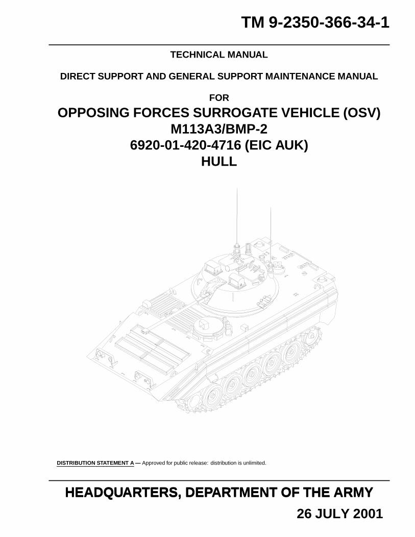
TM 9-2350-366-34-1
TECHNICAL MANUAL
DIRECT SUPPORT AND GENERAL SUPPORT MAINTENANCE MANUAL
FOR
OPPOSING FORCES SURROGATE VEHICLE (OSV)M113A3/BMP-2
6920-01-420-4716 (EIC AUK)HULL
DISTRIBUTION STATEMENT A — Approved for public release: distribution is unlimited.
HEADQUARTERS, DEPARTMENT OF THE ARMYHEADQUARTERS, DEPARTMENT OF THE ARMY
26 JULY 2001

TM 9-2350-366-34-1
HEADQUARTERSDEPARTMENT OF THE ARMY
WASHINGTON, D.C., 26 JULY 2001
TECHNICAL MANUAL
DIRECT SUPPORT AND GENERAL SUPPORT MAINTENANCE MANUAL
OPPOSING FORCES SURROGATE VEHICLE (OSV) M113A3/BMP-2NSN 6920-01-420-4716
(EIC AUK)HULL
REPORTING ERRORS AND RECOMMENDING IMPROVEMENTS
You can help improve this publication. If you find any mistakes or if you know of a way to improve theprocedures, please let us know. Submit your DA Form 2028 (Recommended Changes to Publications and BlankForms), through the Internet, on the Army Electronic Product Support (AEPS) website. The Internet address ishttp://aeps.ria.army.mil. If you need a password, scroll down and click on “ACCESS REQUEST FORM”. TheDA Form 2028 is located in the ONLINE FORMS PROCESSING section of the AEPS. Fill out the form andclick on SUBMIT. Using this form on the AEPS will enable us to respond quicker to your comments and bettermanage the DA Form 2028 program. You may also mail, fax, or E-mail your letter or DA Form 2028 directly to:AMSTA-LC-CI/TECH PUBS, TACOM-RI, 1 Rock Island Arsenal, Rock Island, IL 61299-7630. The E-mailaddress is [email protected]. The fax number is DSN 793-0726 or Commercial (309)782-0762.
DISTRIBUTION STATEMENT A — Approved for public release: distribution is unlimited.
TABLE OF CONTENTS
WP Sequence No.
WARNING SUMMARY
HOW TO USE THIS MANUAL
CHAPTER 1 — INTRODUCTORY INFORMATION WITH THEORY OF OPERATION
GENERAL INFORMATION..............................................................................................................................0001 00
EQUIPMENT DESCRIPTION AND DATA.......................................................................................................0002 00
THEORY OF OPERATION................................................................................................................................0003 00
REPAIR PARTS, SPECIAL TOOLS, TMDE, AND SUPPORT EQUIPMENT................................................0004 00
CHAPTER 2 — DIRECT SUPPORT MAINTENANCE INSTRUCTIONS FOR VEHICLE HULL— GENERAL
SERVICE UPON RECEIPT................................................................................................................................0005 00
PREVENTIVE MAINTENANCE CHECKS AND SERVICES (PMCS), INCLUDINGLUBRICATION INSTRUCTIONS............................................................................................................0006 00
i

TM 9-2350-366-34-1
TABLE OF CONTENTS (cont)WP Sequence No.
CHAPTER 3 — DIRECT SUPPORT MAINTENANCE INSTRUCTIONS FOR ENGINE
REPLACE ENGINE............................................................................................................................................0007 00
REPLACE VARIABLE SPEED DRIVE ASSEMBLY ADAPTER....................................................................0008 00
CHAPTER 4 — DIRECT SUPPORT MAINTENANCE INSTRUCTIONS FOR FUEL SYSTEM
REPAIR/REPLACE ACCELERATOR STOP SUPPORT ASSEMBLY.............................................................0009 00
CHAPTER 5 — DIRECT SUPPORT MAINTENANCE INSTRUCTIONS FOR COOLINGSYSTEM
REPAIR RADIATOR..........................................................................................................................................0010 00
REPAIR RADIATOR AUXILIARY TANK........................................................................................................0011 00
REPAIR FAN AND GENERATOR VARIABLE SPEED DRIVE.....................................................................0012 00
REPAIR VENTILATING FAN ASSEMBLY......................................................................................................0013 00
REPAIR FAN DRIVE SHAFT AND BEARING HOUSING.............................................................................0014 00
CHAPTER 6 — DIRECT SUPPORT MAINTENANCE INSTRUCTIONS FOR ELECTRICALSYSTEM
REPAIR GENERATOR.......................................................................................................................................0015 00
REPLACE WARNING LIGHT PANEL MOUNTING BRACKET...................................................................0016 00
REPAIR BATTERY.............................................................................................................................................0017 00
REPAIR MULTIPIN CONNECTORS................................................................................................................0018 00
REPAIR ENGINE WIRING HARNESS.............................................................................................................0019 00
REPAIR TRANSMISSION WIRING HARNESS..............................................................................................0020 00
REPAIR TRANSMISSION CONTROL WIRING HARNESS..........................................................................0021 00
REPLACE FRONT MAIN WIRING HARNESS...............................................................................................0022 00
REPAIR FRONT MAIN WIRING HARNESS...................................................................................................0023 00
CHAPTER 7 — DIRECT SUPPORT MAINTENANCE INSTRUCTIONS FORTRANSMISSION
REPLACE TRANSMISSION.............................................................................................................................0024 00
CHAPTER 8 — DIRECT SUPPORT MAINTENANCE INSTRUCTIONS FOR FINAL DRIVEASSEMBLIES
REPAIR/OVERHAUL FINAL DRIVE ASSEMBLY.........................................................................................0025 00
CHAPTER 9 — DIRECT SUPPORT MAINTENANCE INSTRUCTIONS FOR WHEELS ANDTRACKS
REPAIR TRACK IDLER ARM..........................................................................................................................0026 00
REPAIR TRACK TENSION ADJUSTER..........................................................................................................0027 00
CHAPTER 10 — DIRECT SUPPORT MAINTENANCE INSTRUCTIONS FOR STEERING
REPAIR STEERING BRACKET AND SHAFT HOUSING BEARINGS........................................................0028 00
CHAPTER 11 — DIRECT SUPPORT MAINTENANCE INSTRUCTIONS FOR SHOCKABSORBERS
REPAIR SHOCK ABSORBER...........................................................................................................................0029 00
ii

TM 9-2350-366-34-1
TABLE OF CONTENTS (cont)WP Sequence No.
CHAPTER 12 — DIRECT SUPPORT MAINTENANCE INSTRUCTIONS FOR HULL
REPLACE SERRATED LOCK RING SCREW INSERTS................................................................................0030 00
REPLACE SERRATED LOCK RING SCREW INSERT WITH PACKING.....................................................0031 00
REPLACE OVERSIZE SCREW INSERTS WITH LOCK RING......................................................................0032 00
REPLACE KEY-LOCKED SCREW INSERTS.................................................................................................0033 00
REPLACE PRESSNUT.......................................................................................................................................0034 00
CHAPTER 13 — DIRECT SUPPORT MAINTENANCE INSTRUCTIONS FOR TOOLS ANDTEST EQUIPMENT
TEST LOAD POWER PLANT SLING...............................................................................................................0035 00
REPAIR POWER PLANT SLING......................................................................................................................0036 00
ADJUST ENGINE AND TRANSMISSION STAND.........................................................................................0037 00
SERVICE ENGINE AND TRANSMISSION STAND.......................................................................................0038 00
REPAIR ENGINE AND TRANSMISSION STAND..........................................................................................0039 00
CHAPTER 14 — DIRECT SUPPORT MAINTENANCE INSTRUCTIONS FOR SPECIALPURPOSE KITS
INSTALL PERSONNEL HEATER KIT.............................................................................................................0040 00
REPAIR PERSONNEL HEATER ASSEMBLY.................................................................................................0041 00
CHAPTER 15 — DIRECT SUPPORT MAINTENANCE INSTRUCTIONS FOR PRECISIONINSTRUMENTS AND SYSTEMS
REPAIR STE/ICE DISTRIBUTION BOX..........................................................................................................0042 00
REPAIR STE/ICE WIRING HARNESS.............................................................................................................0043 00
CHAPTER 16 — DIRECT SUPPORT MAINTENANCE INSTRUCTIONS FOR FIREFIGHTING EQUIPMENT
SERVICE FIRE EXTINGUISHER CYLINDER AND SAFETY DISC............................................................0044 00
CHAPTER 17 — SUPPORTING INFORMATION
REFERENCES....................................................................................................................................................0045 00
COMMON TOOLS AND SUPPLEMENTS AND SPECIAL TOOLS/FIXTURES LIST................................0046 00
FABRICATED TOOLS.......................................................................................................................................0047 00
EXPENDABLE/DURABLE SUPPLIES AND MATERIALS LIST..................................................................0048 00
GENERAL MAINTENANCE INSTRUCTIONS...............................................................................................0049 00
iii/iv blank

TM 9-2350-366-34-1
HOW TO USE THIS MANUAL
HOW TO USE THIS MANUAL
The safest, easiest, and best way to maintain the OSV hull is to use this manual. Learning to use this manual is as easy asreading it. Knowing what is in this manual and how to use it will save you time. Becoming familiar with the work,procedures, and cautions will help you in your job and reduce your exposure to unnecessary hazards.
WHERE DO YOU START
This TM is divided into chapters and front and rear matter. The chapters are further divided into Work Packages (WPs) forease of use. Go to the area within the manual that covers what you are to do and follow the instructions. Be sure to read andfollow the Warnings, Cautions, and Notes.
HOW THIS MANUAL IS ORGANIZED
The WARNING SUMMARY section provides safety and first aid information. This section includes general warnings notfound in the TM text and a list of the most important detailed warnings extracted from the WPs. All of these warnings coverhazards that could kill or injure personnel.
The TABLE OF CONTENTS lists the WPs in each chapter.
CHAPTER 1 covers General Information, Equipment Description and Data, and Theory of Operation. The EquipmentDescription WP gives a brief description of major parts and features of the OSV hull. The Theory of Operation WP providesinformation that will help you understand how the hull components work.
CHAPTERS 2 through 16 include all Direct Support Maintenance WPs for the OSV hull. [At this time, there are no GeneralSupport Maintenance WPs in this document.]
CHAPTER 17 contains supporting information, such as lists of references, tools, expendable/durable items, etc.
The INDEX is an alphabetical listing of all the WPs in this manual. Each entry is cross-referenced to the WP number andpage number.
DA FORM 2028 is used to report errors and to recommend improvements for procedures in this manual. Three blank DAForms 2028 are in the back of this manual.
The back cover includes a METRIC CONVERSION CHART that can be used to convert U.S. customary measurements totheir metric equivalents. Measurements in this manual are given in U.S. customary unit with metric units in parentheses.
HOW TO USE THE WORK PACKAGES
Pick a key word from the hull part or system to be repaired. Look in the INDEX for this key word or the name of the actionyou will perform. Turn to the WP and page indicated.
How to read the WP
WPs provide either descriptive/supporting information or detailed procedures for maintaining/repairing the equipment.
Pay attention to all warnings, cautions and notes. These can appear in all types of procedures. They help you avoid harm toyourself, other personnel, and equipment. They also tell you things you should know about the procedure.
Before you start a procedure, get all the tools, supplies, and personnel you need to do the procedure. These items will belisted in the INITIAL SETUP of the WP.
Start with step 1 and do each step in the order given. Numbered primary steps tell you WHAT to do. Alpha substeps tell youHOW to do it.
Look at the illustrations. Locators show you where the parts are located on the hull or assembly. Close-up illustrations showthe details you need to do the procedure.
The words END OF TASK will tell you when you have finished the procedure.
v

TM 9-2350-366-34-1
HOW TO USE THIS MANUAL (cont)
DEFINITION OF WP TERMS
Warnings, Cautions, And Notes
Pay attention to all warnings and cautions within the WP. Ignoring a warning could cause death or injury to yourself or otherpersonnel. Ignoring a caution could cause damage to equipment. Notes contain facts to make the procedure easier. Warnings,cautions, and notes always appear just above the step to which they apply.
WARNINGS Call attention to things that could kill or injure personnel. Warnings are also listedin the Warning Summary section (page a).
CAUTIONS Call attention to actions or materials that could damage equipment.
NOTES Contain important facts to make the procedure easier.
Helper
Helpers are needed in procedures that require more than one person. A helper may be needed to help lift objects or act as anoutside observer.
If a helper is needed to perform a procedure, the INITIAL SETUP will list “Helper (H)” under the PERSONNELREQUIRED heading.
If a helper assists with a step, the step will include: “Have helper assist”.
If a helper performs the action alone, the step will start with “(H):”.
Location Terms
The terms “front”, “rear”, “left”, and “right” are used to indicate where items are located on the vehicle, turret, and power unit.
THE POINT OF REFERENCE IS DIFFERENT FOR VEHICLE ITEMS AND POWER UNIT ITEMS. Vehicle items areitems not on the power unit. Power unit items are items on the engine or transmission.
If you are working with vehicle items, think of the locations as if you were standing on the ramp facing the inside of thevehicle or sitting in the turret facing the 30mm gun.
RIGHT
REAR
FRONT LEFT
vi

TM 9-2350-366-34-1
HOW TO USE THIS MANUAL (cont)
If you are working with power unit items, think of the locations as if you were standing at the transmission end of the powerunit and facing the flywheel. This rule applies whether the power unit is IN or OUT of the vehicle.
LEFT
FRONT
REAR
RIGHT
vii/viii blank

TM 9-2350-366-34-1
CHAPTER 1
INTRODUCTORY INFORMATION WITH THEORY OF OPERATION
WORK PACKAGE INDEX
Title Sequence No.
GENERAL INFORMATION.............................................................................................................................................0001 00
EQUIPMENT DESCRIPTION AND DATA.....................................................................................................................0002 00
THEORY OF OPERATION...............................................................................................................................................0003 00
REPAIR PARTS, SPECIAL TOOLS, TMDE, AND SUPPORT EQUIPMENT...............................................................0004 00

TM 9-2350-366-34-1
GENERAL INFORMATION 0001 00
SCOPE
This manual tells you how to perform Direct Support and General Support Maintenance on the automotive/hull parts of theOSV M113A3/BMP-2. It contains information you need to know in order to maintain and repair the hull and hull systems. Ittells you what to do and what not to do, and how to protect the safety of yourself and others. TM 9-2350-366-34-2 tells howto maintain/repair the turret parts of the M113A3/BMP-2.
Type of Manual: Direct Support and General SupportEquipment Name: Opposing Forces Surrogate Vehicle M113A3/BMP-2 — HullPurpose of Equipment: Visually and tactically represent the Soviet BMP-2 Infantry Fighting Vehicle
MAINTENANCE FORMS, RECORDS, AND REPORTS
Department of the Army forms and procedures used for equipment maintenance will be those prescribed by DA PAM738-750, The Army Maintenance Management System (TAMMS).
REPORTING EQUIPMENT IMPROVEMENT RECOMMENDATIONS (EIR)
If your M113A3/BMP-2 needs improvement, let us know. Send us an EIR. You, the user, are the only one who can tell uswhat you don’t like about your equipment. Let us know why you don’t like the design or performance. Put it on an SF 368(Product Quality Deficiency Report). Mail it to us: Director, U.S. Army Armament Research, Development, and EngineeringCenter, ATTN: AMSTA-AR-QAW-A (R), Rock Island, IL 61299-7300. We will send you a reply.
CORROSION PREVENTION AND CONTROL (CPC)
Corrosion Prevention and Control (CPC) of Army materiel is a continuing concern. It is important that any corrosionproblems with this item be reported so that the problem can be corrected and improvements can be made to prevent theproblem in future items.
While corrosion is typically associated with rusting of metals, it can also include deterioration of other materials such asrubber and plastic. Unusual cracking, softening, swelling, or breaking of these materials may be a corrosion problem.
If a corrosion problem is identified, it can be reported using Standard Form 368 (Quality Deficiency Report). Use of keywords such as “corrosion”, “rust”, “deterioration” or “cracking” will assure that the information is identified as a CPCproblem. The form should be submitted to: Commander, US Army Tank-automotive and Armaments Command, ATTN:AMSTA-TR-E, Warren, MI 48397-5000.
DESTRUCTION OF ARMY MATERIEL TO PREVENT ENEMY USE
The following manuals tell you how and when to destroy Army materiel to prevent enemy use:TM 43-0002-33TM 750-244-2TM 750-244-6TM 750-244-7
PREPARATION FOR STORAGE OR SHIPMENT
See DA PAM 738-750 for information about administrative storage of the IFV, CFV, and components. SeeTM 55-2350-252-14 for information about transportability of the vehicles.
0001 00-1

TM 9-2350-366-34-1
GENERAL INFORMATION — Continued 0001 00
NOMENCLATURE CROSS-REFERENCE
The following list provides nomenclature cross-references for common terms used in this manual.
Common Name Official Nomenclature
Bilge pump Rotary pump unit
Cleaning solvent Cleaning compound solvent
Dipstick with tube Rod gauge with tube
Dust cap Connector plug
Fan control box Vent van controller
Hydroelectric power unit Ramp power unit
Jack Receptacle
Lead Terminal
Lock screw Self-locking bolt
Lock wire Nonelectrical wire
Locknut Self-locking nut
O-ring Preformed packing
Personnel heater Compartment vehicle heater
Plastic face hammer Inserted hammer face
Plug Connector
Prussian blue dye Prussian blue paste
Pulsation damper Inertia damper
Push rod cover Push tube cover
Snap ring pliers External retaining ring pliers
Sealing washer Packing with retainer
Transmission coupling Vibration damper
SAFETY, CARE, AND HANDLING
Read warnings in Warning Summary (page a) and within the WPs.
0001 00-2

TM 9-2350-366-34-1
EQUIPMENT DESCRIPTION AND DATA 0002 00
EQUIPMENT CHARACTERISTICS, CAPABILITIES, AND FEATURES
For equipment characteristics, capabilities, and features, see TM 9-2350-366-10-1.
LOCATION AND DESCRIPTIONS OF MAJOR COMPONENTS
FINALDRIVE
TRANSMISSION
ENGINE
ENGINE, MECHANICAL:
The turbocharged diesel engine is the primary power source for the vehicle. It is located in the power plant compartment.
TRANSMISSION:
An automotive transmission connects to the engine and powers the final drive.
FINAL DRIVE:
Final drives attach to the transmission by propellor shafts. They deliver power to drive sprockets at the front of the vehicle.
0002 00-1

TM 9-2350-366-34-1
EQUIPMENT DESCRIPTION AND DATA — Continued 0002 00
TRACK AND SUSPENSION:
Drive sprockets at the front of the vehicle drive track. Torsion bars and shock absorbers attach to road wheels and providesuspension.
IDLER WHEEL
ROAD WHEELTRACK
SHOCKABSORBER
SPROCKET
TRACKADJUSTER
ROAD WHEELARM
TORSIONBAR
ELECTRICAL:
Four batteries, connected in a parallel series arrangement, supply electricity through the distribution box to the vehicle. Onthe OSV, the four batteries are located on the right sponson.
0002 00-2

TM 9-2350-366-34-1
EQUIPMENT DESCRIPTION AND DATA — Continued 0002 00
FUEL SYSTEM:
The OSV vehicles have two external fuel tanks located at the rear of the vehicle on each side of the ramp. Total capacity is 95gallons.
FUEL TANKS
EXHAUST SYSTEM:
The exhaust system drives the turbocharger and carries exhaust gases through manifolds and the muffler.
EXHAUSTEXTENSION
EQUIPMENT DATA
For equipment data, see TM 9-2350-366-10-1.
0002 00-3/4 blank

TM 9-2350-366-34-1
THEORY OF OPERATION 0003 00
SCOPE
This section describes the functions of the M113A3/BMP-2 hull systems, including the power unit, auxiliary automotivesystems, suspension system, and electrical system.
POWER PLANT
The OSV power unit includes the engine, transmission, DC generator, exhaust system, cooling system, and air intake system.
Engine, Diesel:
The diesel engine is the primary power source for the vehicle. The engine changes air and diesel fuel into energy and deliversthis power to the transmission. The diesel engine consists of three major systems: fuel, oil, and starting.
In the fuel system, diesel fuel is stored in the fuel tanks. The fuel is drawn through one filter and pumped through the otherfilter to the engine. The injectors force fuel into combustion cylinders where it is mixed with air and changed into energy.
The oil system provides lubrication for the engine. Oil is cycled throughout the engine by a pump. The pump is located at thelower front of the engine. An oil filter cleans the oil, and an oil cooler reduces oil temperature.
The engine is equipped with a heavy-duty starter. The starter, with built-in solenoid, is used to crank the engine for starting.
Transmission:
The vehicle uses a hydromechanical transmission with hydrostatic steering. The transmission has its own oil system withfilter and separately mounted oil cooler. This transmission oil system is separate from the engine oil system.
The transmission delivers power from the engine to the left and right final drives. The left and right final drives are driven bypropeller shafts. The final drives deliver power to drive sprockets in the suspension system.
DC Generator:
The DC generator is part of the vehicle electrical system. It is driven directly by engine power. The generator charges thebatteries in the vehicle when the engine is running. A regulator mounted near the driver keeps the voltages at the correct level.
Exhaust System:
Major exhaust system parts are the turbocharger, exhaust manifolds, and muffler.
The turbocharger is driven by exhaust gases from the engine. The turbocharger helps the engine develop more power andoperate more efficiently. The exhaust manifolds carry the exhaust gases to the turbocharger from the engine. The muffler cutsdown engine nose and allows exhaust to escape outside the vehicle.
Cooling System:
The cooling system cools the engine and transmission. It consists of a fan, fan drive, fan speed control assembly, radiator,coolant pump, auxiliary tank, transmission oil cooler, and thermostats. The cooling system contains approximately 53 quartsof liquid coolant. The liquid coolant is cycled through the engine and transmission oil cooler by the coolant pump. Thisprocess keeps the engine and transmission temperature in a safe operation range.
As coolant flows through the engine, it absorbs heat from the engine and transmission oil coolers. The heated coolant thenflows to the radiator to remove coolant heat. The coolant fan pull outside air in and through the radiator to remove heat. Thefan is powered by the engine through a fan drive.
The variable-speed fan drive system is designed to modulate the cooling fan speed to maintain relatively constant coolanttemperatures despite vehicle load or ambient temperature. The cooling fan speed is controlled by the fan drive assembly. Thefan drive assembly is driven by the engine crankshaft through a splined coupling. The fan drive assembly contains amultiplate clutch pack that regulates the fan drive output speed. The thermostatic control valve senses engine coolant
0003 00-1

TM 9-2350-366-34-1
THEORY OF OPERATION — Continued 0003 00
temperature and regulates the hydraulic pressure to the fan drive assembly clutch pack. The higher the coolant temperature,the higher the hydraulic pressure, which results in less clutch slip and higher fan speed.
The surge tank acts as an overflow tank to keep the cooling system from overpressuring. It also removes air from the enginecoolant. There is a low coolant level transmitter to signal the operator if more coolant is needed.
Air Intake System:
The engine air intake system allows air to enter the engine. The air cleaner cleans air that enters the engine. Dust is drawn outthrough a scavenge outlet. Air is filtered through a reusable filter element before delivery to the engine. An air filter indicatorshows when the element is clogged and needs cleaning or replacing. After being filtered, the air moves through theturbocharger and into the engine cylinders.
AUXILIARY AUTOMOTIVE SYSTEMS
The auxiliary automotive systems includes driver controls, fuel tanks, personnel heater, bilge pumps, and fire extinguishersystem.
Driver Controls:
The driver controls regulate the engine, transmission, steering, and braking systems of the vehicle.
The fuel shut-off control is used to stop the supply of fuel to the fuel pump. To start the engine, the driver must open thevalve. The throttle linkages are used to control the engine speed. The gear selector allows the driver to choose the proper gearfor the vehicle. The steering system controls the vehicle direction. The steering control consists of a steering yoke andlinkage connected to the transmission.
The brake system allows the driver to stop a moving vehicle and hold the vehicle in position. The braking system consists ofthe service brake and the parking brake. The service brakes are hydraulic and are applied by pedal. The parking brakemechanically locks the transmission to prevent vehicle movement. Also, the system has levers, rods, shafts, and linkagesconnecting to the transmission’s brake shaft.
Fuel Tanks:
Diesel fuel is stored in two separate fuel tanks. They are located on the back of the vehicle hull. The fuel is drawn from thefuel tanks through the primary fuel filter by the fuel pump. The fuel then flows through the secondary fuel filter to theinjectors. The injectors regulate the amount of fuel which enters the engine.
Personnel Heater:
The personnel heater system provides heat inside the vehicle. Major parts are the combination combustion chamber/heatexchanger, blowers, a fuel pump, and an electric control and safety system. The heater is operated by diesel fuel drawn fromthe fuel tanks. Fuel is delivered to the combustion chamber from the fuel pump. Outside air is drawn into the combustionchamber by one of the blowers. A blower draws air from the crew compartment into the combustion chamber. The air iswarmed by heat from the combustion process and then returned to the crew compartment.
Bilge Pumps:
One electrically driven bilge pump removes water and other liquids from the hull. Water enters the pump through a screenedinlet. The pump forces water out of the vehicle through an outlet tube. The bilge pump is controlled by a switch on thedriver’s instrument panel.
Fire Extinguisher System:
The fire extinguisher system will detect and put out fires in the vehicle. It consists of two Carbon Dioxide (CO2) cylinders.CO2 can put out fires quickly and effectively. The cylinders are operated manually by pulling cables located in the hull.
0003 00-2

TM 9-2350-366-34-1
THEORY OF OPERATION — Continued 0003 00
There is a fire extinguisher located in the driver’s compartment that is manually discharged into the engine compartment.Another extinguisher is located in the personnel compartment.
SUSPENSION SYSTEM
The suspension system supports the vehicle and delivers engine power to the road. It allows the vehicle to maneuver and bestable. Suspension system parts are the drive sprockets, tracks, idler wheels, track adjuster, road wheels, and road wheelsupport arms. Also, there are torsion bars and shock absorbers.
The drive sprockets drive the tracks. They are powered by left and right final drives from the transmission. The tracks consistof two flexible chains of track shoes. The tracks ride on the drive sprockets and are guided by idler wheels. The idler wheelscan be adjusted to maintain correct track tension.
There are five pairs of road wheels per side. Track guides fit between each pair of road wheels. All road wheels are connectedto road wheel support arms.
ELECTRICAL SYSTEM
The electrical system provides power for the vehicle. The system operates on wet cell batteries and includes charging,regulating, and monitoring equipment. The batteries provide a normal operating 24 volts with an amperage capability of 200amps per hour.
The batteries supply the vehicle with electricity when the engine is off. All electrical power is delivered through thedistribution box, except for the engine coolant heater and personnel heater, which are directly powered from the batteries.Electrical power flows from the batteries through the distribution box, cables, and wiring assemblies to the hull. The hull is aground for the electrical system.
The DC generator recharges the batteries and supplies electricity while the engine is running. The DC generator has 200 ampsper hour capability.
There are several electrical subsystems within the hull. Each subsystem contains at least one wiring assembly. Majorelectrical subsystems and assemblies include the interior and exterior lights, fuel supply, starting and charging systems,ventilation, heating, and bilge pump.
0003 00-3/4 blank