public version of emergency plan implementing procedure
TRANSCRIPT
.-. . .
a . 1- .
4- c,-
,y '
< f
- GEDRGIA POWER COMPANY'>,
f
. #
t HATCH NUCLEAR PLANTi
| PROCEDURE i
t
! !
.| GUANTITATTVE FIT TFSTTNG..
-PROCEDUR!:. TITLE--
,
!
HNP-RO77a-
PROCEDURE NUMBER,.|
1. ARI
RESPONGIDLE SECTION,
6.
.s*
f SAFETY RELATED ( ) NON-SAFETY RELATED ( X )f
.f
.,
IJ
6,
APPROVED API'RDVED.
!
j REV. DESCRIPTION DEPT. PLANT DATEHEAD MANAGER'
... . - - - - - - - - - - - - - - - - - - - - .-------.. ------ --- - -- ya---- p -------
[ gy [< g,hk-. ----.
0 New Procedure /,
7------
---------------------------- . - - - - - - - . --- -----.. --- ----
.:.-
.
------..--.-----------------.. --------------- ---------------.. y - - - - - -...:....
y--------.; ------.. . - - - - - - - - - . - - - - - - - . . . ..---------------- .----------------
.N
F-_----__0- .-_----_-_---_---.----- .----_--_--.----_---_.. - _ _ - - - _ - - - - - - - _ - .
,
% F-------.. - - _ _ - - - - - - - - - _ - - - -------_---_----p---_----___-_--_____.. ------
.
g--_--_---_--_--------_--_---------- . - - - - - - - - - - - - - - - - .._---------_---__,
' y-------.------.----------------------.----------------..-----. -----------
y--------. ---------------..---------- -----------.----------------------
- - - - - - .---------------------..---------------- .----------------.---------
.---------------- .-------- - - . ------ -------.. - - - - - - - - - - - - - - - - - - - .
.t* |* ------ , . - - - - - - - -y.----- .--.. ----------------..------------
.--_-- - - - _ - _ _ - - _ _ - - _ _ _ - - _ ..- _ - - - _ _.. - - _ - - -- .- ----- ___-__---
1.
------ --------------------..---------------- .- ------------ --------
---- - ----------.---------.. - - - - - - - - - - - - - - . . . . - - - - - - - - - - - - - - - - -----.--
------.. ------------------- .---------------- ----------------- --------
't
8206020081 820525 HNP-9PDR ADOCK 05000321 -
F PDR .
9 - mee
manual set..w.
.
& 6.N. [///[[?'
-: , .
, . PRDCFDt 'RE RFVTrH. RFor tF9T=-- p---------. - - - - -.
. . ,'
FOR NEW PROCEDttRE,
!
.fj PROCEOLtRE t:0. HNo _ fjf/0-(0[ 5 .
_., _
SAFETY RrlATFD ( ) NON-SAFETY RFLATFD-
,
FCUUSED RY DFP ARTMENT F_-tFAD __ AEP500AL__~~~~ -
3
Niw.o : Date: Signature: Date:.
?3 - 2 V~- A|, /|,)-[ V/
;
":
~
.
. .,
.
f Attach marked up copy of procedure to this form.
f,_ $thREASON FOR REGUE.ST__ [ l ' g:&t e 4_rans,x'2dts
f C| c~
|8i
~m#{ _ )f,| | -
*
. 'hi .
';
::
_
. ...
s .
> .
<
,
~,
9?
-.
i
,
_-off
D~= g ,-
A4M'
--- ypk u
_
.
-
__ _
.
PRD RECOM. MENDS APPPOVAL: (-tTN ( )No ,,y _-~
mA_ _ , ' PRG secretary.
i
- ..
,f? _ T Y / 8 '[_L .,,
PRO t1umbe r ' D#.t e ..,
' *
HNP-94 - .
.
. . . _ ..... 4~
manual set.
.
. .: . - ... . -; .
:<; .
*:- .- .q.
,. 5 . w tuvat w
E. l. HATCH NUCLEAR PLANT HNP-8033. t ,,n -
See Title Pace A Ooa's
GeorgiaPower nA~~
1 of 14Soo Title Paqe
..
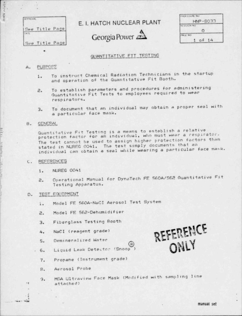
GlfANTITATIVE FIT TFSTING.
A. PURPDFE7
1. To instruct Chemical Radiation Technicians in the startupand operation of the Guantitative Fit Booth.
.
I 2. To establish parameters and procedures for administeringGuantitative Fit Tests to employees required to wear'
respirators.,
To document that an individual may obtain a proper seal with~
3.I a particular face mask.!
8. G_ENERAL
Guantitative Fit Testing is a means to establish a relative' protection factor for an individual, who must wear a respirator,''
The test cannot be used to assign higher protection factors than?
-
[ stated in NUREG 0041. The test simply documents tha t an
findividual can obtain a seal while wearing a particular face mask.
C. REFFRENCESg
E 1. NUREG 0041A for DynaTech FE 560A/562 Guantitative Fit2. Operational Manualj Testing Apparatus.
3 D. TEST FOUIPMENT.
I 1. Model FE 560A-NaCI Aerosol Test System
2. Model FE 562-Debumidifier
3. Fiberglass Testing Booth
Os.p. 5R* F_h$4. NaCI (reagent grade) -
beAs5. Demineralized Water
6. Liquid Leak Detector (Snoop ).
7. Propane (Instrument grade)
8. Aerosol Probe
9. MSA Ultraview Face Mask (Modified with sampling line?' attached)
.
t'
.
_ . .u. 4manual set-
_
li l'
-
;. -
5 , mm e,r -
E.1. HATCH NUCLEAR PLANT HNP-803''.i-tw e e uoSee Title Page
4 0' ' ' '
Georgia Power an ~~
2 of 14See Title Page
, ..
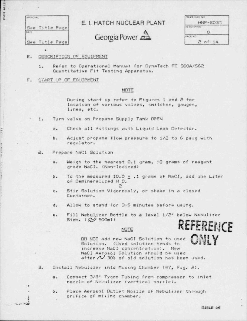
E. DESCRIPTION _OF FOUIPMENT*
. 1. Refer to Operational' Manual for DynaTech FE 560A/5624 Ouantitative Fit Testing Apparatus.
F. START ltP OF EGUIPMENT
. ..
NOTE,
i During start up refer to Figures 1 and 2 forlocation of various valves, switches, gauges,
I.lines, etc.'
| 1. Turn valve on Propane Supply Tank OPEN-
g; a. Check all fittings with Liquid Leak Detector.T-
b. Adjust propane flow pressure to 1/2 to 6 psig withe - regulator.8
h 2. Prepare NaCI Solution:
a. Weigh to the nearest 0.1 gram, 20 grams of reagent7 grade NaCI. (Non-Iodized)g . . ~
j b. To the measured 10.0 i .1 grams of NaCI, add one Literof Demineralized H O.
2.
!.c. Stir Solution Vigorously, or shake in a closed
Container.f.j d. Allow to stand for 3-5 minutes before using.
e. Fill Nebulizer Bottle to a level 1/2" below NebulizerM
. Stem. ( n,/ SOOml )
__NOTE
-
IyDO NOT add new NaCI Solution to used5cluIion. (Used solution tends to w sh $. I <
iincrease NaCI concentration). NewNaCI Aerosol Solution should be used-
af ter /t/ 30% of old solution has been used.
3. Install Nebulizer into Mixing Chamber (#7, Fig. 2).|
|
| a. Connect 3/8" Tygon Tubing from compressor to inlet| nozzle of Nebulizer (vertical nozzle).
8
: .b . Place Aerosol Outlet Nozzle of Nebulizer through
. $orifice of mixing chamber.
.,
I ., ''bO-,
! manual set
'{ . .
-
2
{ m+Decs MLousa w
* E. l. HATCH NUCLEAR PLANT HNP-8033'
See Title Page * * * * *
ua'e A O.
Georria Power dA ~~dSee Title Pace 3 of 14
..'
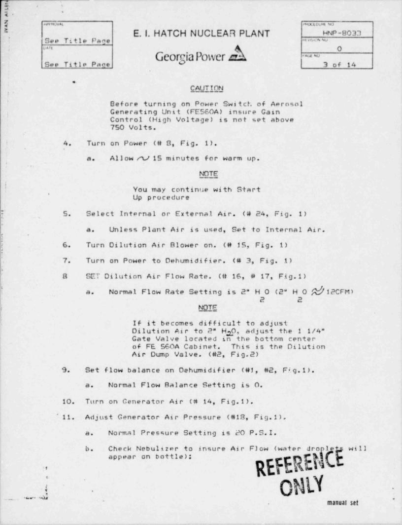
CAUTTONp. - - -
'Before turning.on Power Switch of AerosolGenerating Unit (FE560A) insure Gain,
'Control (High Voltage) is not set above750 Volts.
t 4. Turn on Power (# 8, Fig. 1).,
a. Allow et/15 minutes for warm up.
NOTE
You may continue with Start'
Up procedure
[ ,5. Select Internal or External Air. (# 24, Fig. 1)
.
Unless Plant Air is used, Set to Internal Air.a.!
*
i . 6. Turn Dilution Air Blower on. (# 15, Fig. 1)
7. Turn on Power to Dehumidifier. (# 3, Fig. 1).
.
8 SET Dilution Air Flow Rate. (# 16, # 17, Fig.1)
! Normal Flow Rate Setting is 2" H O (2" H O $b'12CFM)a. /2 2
i NOTE
If it becomes difficult to adjustDilution Air to 2" H 0, adjust the 1 1/4"3Gate Valve located in the bottom centerof FE 560A Cabinet. This is the Dilution
| Air Dump Valve. (#2, Fig.2)i
9. . Set flow balance on Debumidifier (#1, #2, Fi. g .1 ) .
a. Normal Flow Balance Setting is O.
10. Turn on Generator Air (# 14, Fig.1).
l' 11. Adjust Generator Air Pressure (#18, Fig.1).
a. Normal Pressure Setting is 20 P.S.I.
b. Check Nebulizer to insure Air Flow (water dro)1 will
REFEREN1appear on bottle):
.
j ORY~
-.
- . . --
manual set.
.
-
r=' :: -
. .q.=g as m et *mapuut av
~'
E. l. HATCH NUCLEAR PLANT HNP-8037.See Title Page at u-m ~u
h 0sast
Georgia Power cA m-See Title Paqe 4 op 14
...
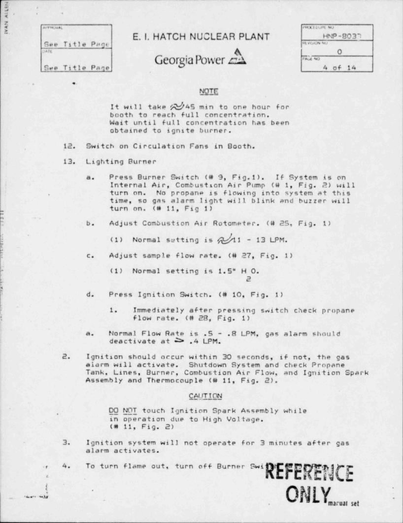
NOTE
It will take yhd45 min to one hour forbooth to reach full concentration.Wait until full concentration has beenobtained to ignite burner.
12. Switch on Circulation Fans'in Booth.,
13. Lighting Burner
a. Press Burner Switch (# 9, Fig.1). If System is oni Internal Air, Combustson Air Pump (# 1, Fig. 2) will
turn on. No propane is flowing into system at thisi.
time, so gas alarm light will blink and^ buzzer willturn on. (# 11, Fig 1)
: b. Adjust Combustion Air Rotometer. (# 25, Fig. 1)
settingis(bhti - 13 LPM.(1) Normal
~
c. Adjust sample flow rate. (# 27, Fig. 1):
i (1) Normal setting in 1.5" H 0.
hd. Press Ignition Switch. (# 10, Fig. 1)
!-
1. Immediately after pressing switch check propanei flow rate. (# 28, Fig. 1)
'
Normal Flow Rate is .5 .8 LPM, gas alarm shoulda.deactivate at 2> .4 LPM.
2. Ignition should occur within 30 seconds, if not, the gasalarm will activate. Shutdown System and check PropaneTank. Lines, Burner, Combustion Air Flow, and Ignition SparkAssembly and Thermocouple (# 11, Fig. 2).
CAUTION
- DO NOT touch Ignition Spark Assembly whilein operation due to High Voltage.(# 11, Fig. 2)
3. Ignition system will not operate for 3 minutes after gasalarm activates.
turn off Burner SwiREFEEqu Cr:;r 4. To turn flame out, p
ix.
- .-. J ONLY'
-
-.
marual set.
<
|9 '
.-2-
7 swAtfut wh mwv4
E. l. HATCH NUCLEAR PLANT HNP-8077* * * * *
See Title Pace ,
GeorgiaPower Aouun
~~ ,
5 nf 14Ree Title Paae
..
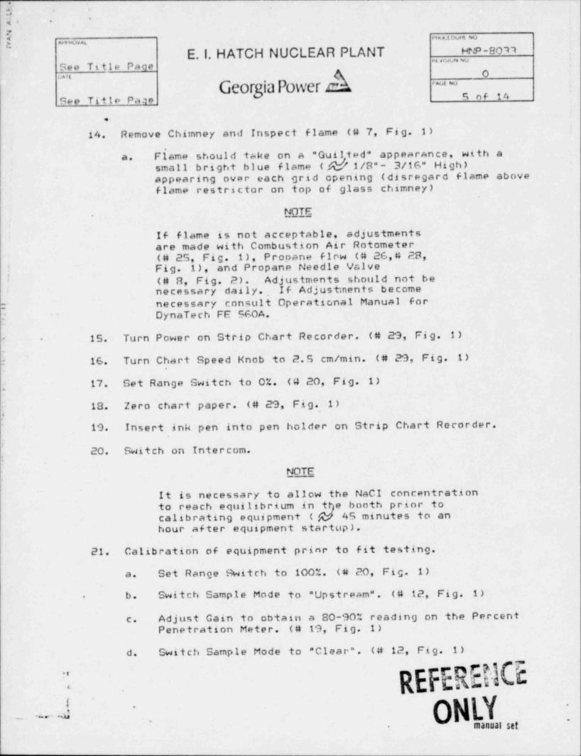
14. Remove Chimney and Inspect flame ( # 7, Fig. 1)
Fiame should take on a "Guilted" appearance, with aa. M( /u/ 1/8"- 3/16" High )small bright blue flame^ appearing over each grid opening (disregard flame above
flame restrictor on top of glass chimney)
NOTE.
If flame is not acceptable, adjustments-
are made with Combustion Air Rotometer(# 25, Fig. 1), Propane f1rw (# 26,4 28,
i Fig. 1), and Propane Needle ValveI (# 8, Fig. 2). Adjustments should not be
necessary daily., If Adjustments become
r necessary consult Operational Manual forDynaTech FE 560A.'
15. Turn Power on Strio Chart Recorder. (# 29, Fig. 1)- -
E 16. Turn Chart Speed Knob to 2.5 cm/ min. (# 29, Fig. 1),
f 17. Set Range Switch to 0%. (# 20, Fig. 1)
: 18. Zero chart paper. (# 29, Fig. 1)i
19. Insert ink pen into pen holder on Strip Chart Recorder.i
20. Switch on Intercom.g
NOTE'
|
It is necessary to allow the NaCI concentrationto reach equilibrium in ttje booth prior tocalibrating equipment ( @ 45 minutes to anhour after equipment startup).
21. Calibration of equipment prinr to fit testing.
a. Set Range 9 witch to 100%. (# 20, Fig. 1)
b. Switch Sample Mode to " Upstream". (# 12, Fig. 1).
Adjust Gain to obtain a 80-90% reading on the Percentc.Penetration Meter. (# 19, Fig. 1)
d. Switch Sample Mode to " Clear". (# 12, Fig. 1)
REFERENG".
.
J. ONI.Y
-~
_. .
manual set.
. - _.
:E -. ,
y ~..
#a... . .m.i ov.a w
E.1. HATCH NUCLEAR PLANT HNP-8033.
See Title Page * " ^ * **
GeorgiaPower AOunt
~~
See Title Page 6 of 14
.
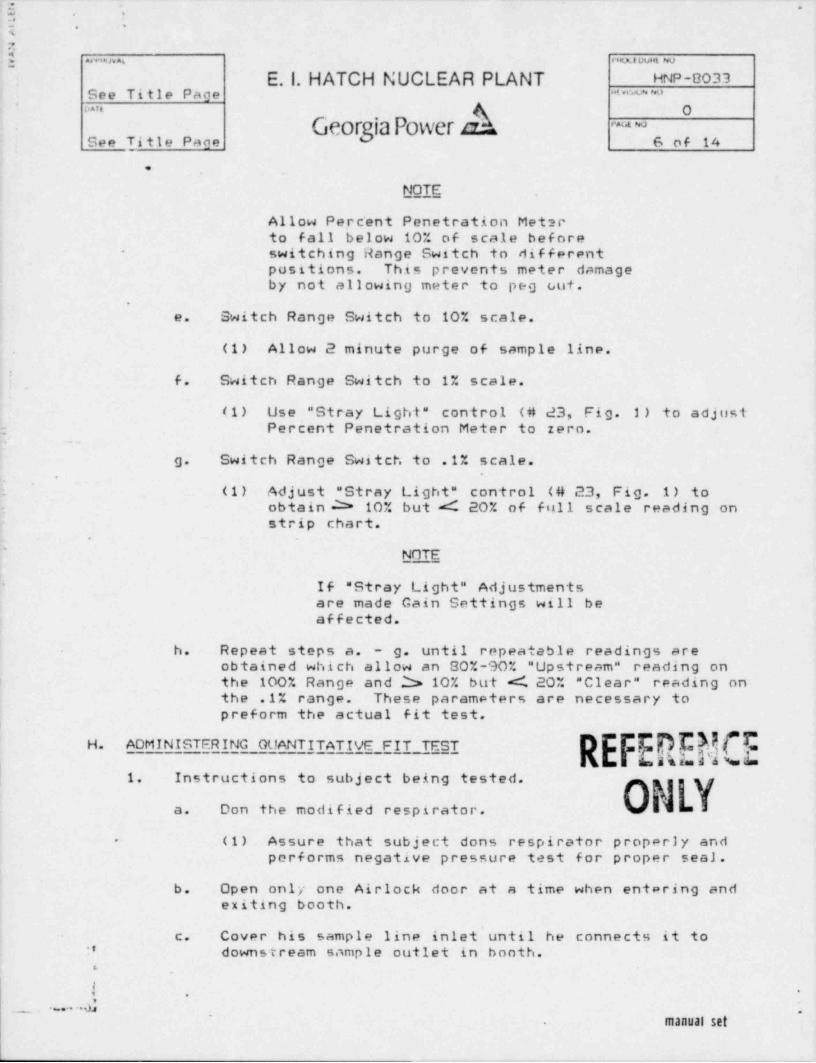
NOTE
Allow Pe.rcent Penetration Meterto fall below 10% of scale beforeswitching Range Switch to different-
~
positions. This prevents meter damageby not allowing meter to peg out.
.
e. Switch Range Switch to 10% scale.
(1) Allow 2 minute purge of sample line.
!, f. Switch Range Switch to 1% scale.
(1) Use " Stray Light" control (# d3, Fig. 1) to adjust: Percent Penetration Meter to zero,
g. Switch Range Switch to .1% scale.
; (1) Adjust " Stray Light" control (# 23, Fig. 1) to- obtain 25 10% but ed 20% of figli scale reading on
strip chart..
'
NOTE
If " Stray Light" Adjustments'
are made Gain Settings will beaffected.
h. Repeat steps a. - g. until repeatable readings areobtained which allow an 80%-90% " Upstream" reading onthe 100% Range and 2> 10% but <C 20% " Clear" reading onthe .1% range. These parameters are necessary topreform the actual fit test.
H. ADMINISTERING GUANTITATIVE FIT TEST (hh5. 5 6m a s na d 4 V==
| 1. Instructions to subject being tested.
a. Don the modified respirator. W =3
(1) Assure that subject dons respirator properly and-
performs negative pressure test for proper sea).
b. Open only one Airlock door at a time when entering andexiting booth.
c. Cover his sample line inlet'until he connects it to:' downstream sample outlet in booth..
! ..
_ . a d5~
manual set-
.
'_ _ _ _ _ _ _ _ _ _
,.
n -
-;. .
'] |. mun .xa vue. o- E. l. HATCH NUCLEAR PLANT HNP-803"t I
See Title Pace " " * * *
'~
Georgia Power ah ~~
7 of 14See Title Pace
..
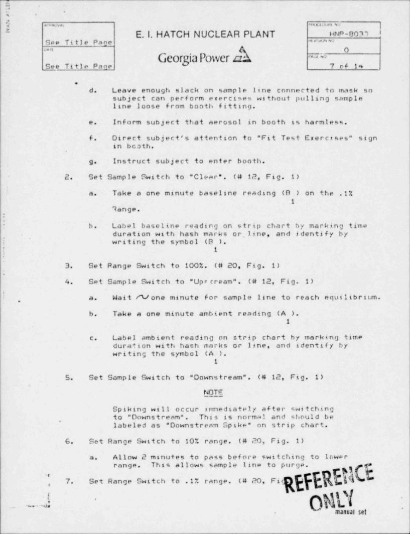
d. Leave enough slack on sample line connected to mask sosubject can perform exercises without pulling sampleline loose from booth fitting.
e. Inform subject that aerosol in booth is harmless.
f. Direct subject's attention to " Fit Test Exercises" signin bcath.
.
g. Instruct subject to enter booth.
2. Set Sample Switch to " Clear". (# 12, Fig. 1).
a. Take a one minute baseline reading (9 ) on the .1%1
7ange.,
Ib. Label baseline reading on strip chart by marking time-
duration with hash marks or line, and identify by., ,
.writing the symbol (8 ).
5 1
'
3. Set Range Switch to 100%. (# 20, Fig. 1).
4. Set Sample Switch to "Upr cream". (# 12, Fig. 1)
! Wait rt/ one minute for sample line to reach equilibrium.a.,
b. Take a one minute ambient reading (A ).1
c. Label ambient reading on strip chart by marking timeduration with hash marks or line, and identify bywriting the symbol (A ).
1
5. Set Sample Switch to " Downstream". (# 12, Fig. 1)a
NOTE
Spiking will occur immediately after switchingto " Downstream". This is normal and should be
,
labeled as " Downstream Spike" on strip chart.
6. Set Range Switch to 10% range. (# 20, Fig. 1)
a. Allow 2 minutes to pass before switching to lowerrange. This allows sample line to purge. =
7. Set Range Switch to .1% range. (# 20, Fi<,
fk i_. . .. ..b*
manual set.
r .
-
:; *
.
;. ..,4m a .w u vum o
5 E. l. HATCH NUCLEAR PLANT HNP-8033,
See Title Page "* '*u
Georgia Power nkOomit
' ~~
See Title Pagel 8 of 14
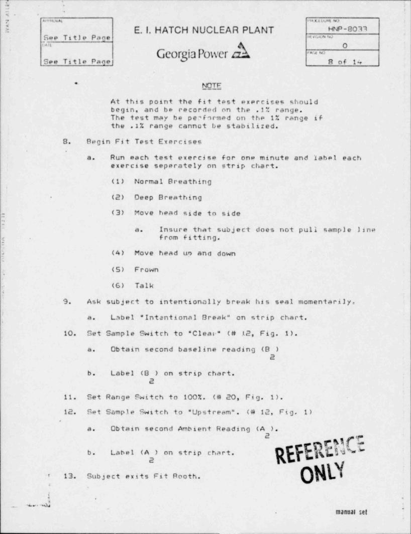
* NOTF
At this point the fit test exercises shouldbegin, and be recorded on the .1% range.The test may be performed on the 1% range ifthe .1% range cannot be stabilized.
8. Begin Fit Test Exercises.
a. Run each test exercise for one minute and label eachexercise seperately on strip chart.
(1) Normal Breathing.
(2) Deep Breathing-
- (3) Move head side to side2-
a. Insure that subject does not pull sample linee from fitting.:
2 (4) Move head up and down:
(5) Frown,
(6) Talk4
9. Ask subject to intentionally break his seal momentarily,
a. Label " Intentional Break" on strip chart.
10. Set Sample Switch to " Clean" (# .t 2, Fig. 1).
a. Obtain second baseline reading (B )2
b. Label (9 ) on strip chart.2
,
11. Set Range Switch to 100%. (# 20, Fig. 1).
12. Set Sample Switch to " Upstream". (# 12, Fig. 1).
a. Obtain second Ambient Reading (A ).& h,
hSNb. Label (A ) on strip chart.
: 13. Subject exits Fit Rooth.
! ..
_ .u . . A_
manual set_
.
E-.a. .
2 .wu oveo w ,
[ '**'*4 '
E. l. HATCH NUCLEAR PLANT HNP-BOM~
*ve wSee Title Page
Geor iaPower A~
~~
See Title Pane 9 of 14
..
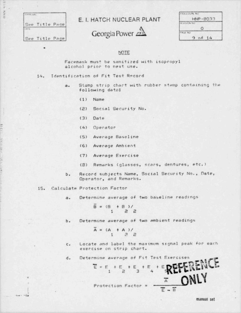
NOTE
Facemask must be sanitized with isopropylalcohol prior to next use.
14. Identification of Fit Test Record
a. Stamp strip chart with rubber stamp containing the, ,
following dato:
(1) Name
! (2) Social Security No.! .
(3) Date
E ~ (4) Operator
(S) Average Baseliney .
=
3 (6) Average Ambient1
(7) Average Exercise1J
(8) Remarks (glasses, scars, dentures, etc.)
Sb. Record subjects Name, Social Security No., Date,'
Operator, and Remarks.
15. Calculate Protection Factor
a. Determine average of two baseline readings
B= (B +B )/1 2 2
~
1. b. Determine average of two ambient readings
A= (A + A )/1 2 2
c. Locate and label the maximum signal peak for each.
exercise on strip chart.
d. Determine average of Fit Test Exercises
E=E +E tE +E tE
o%\XxProtection Factor = _ _
E-8 ,
-. n. 4manual set
*.
_
5 .
5. -
.
y .m,,= mw- w.
* E. l. HATCH NUCLEAR PLANT HNP-8033See Title Page ""'x^*
Georgia Power AOan
~~
10 of 14See Title Page
..
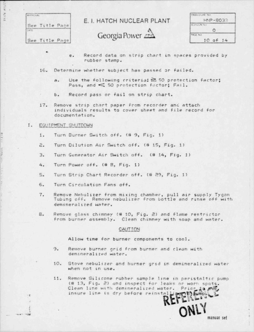
e. Record data on strip chart in spaces provided byrubber stamp.>
16. Determine whether subject has passed or failed.
a. Use the following criteria: $1 50 protection factor;'
Pass, and << 50 p rote ction factor; Fail.
b. Record pass or fail on strip chart.-
17. Remove strip chart paper from recorder and attachindividuals results to cover sheet and file record fordocumentation.;
:
I. EGUIPMENT SHUTDOWN<
{ 1. Turn Durner Switch off. (# 9, Fig. 1):
2. Turn Dilution Air Switch off. (# 15, Fig. 1)i
~
f . 3. Turn Generator Air Switch off. (# 14, Fig. 2) '
E4. Turn Power off. (# 8, Fig. 1)
1
5. Turn Strip Chart Recorder off. (# 29, Fig. 1)i
! 6. Turn Circulation Fans off. i
~
: 7. Remove Nebulizer from mixing chamber, pull air supply Tygon .
Tubing off. Remove nebulizer from bott1e and rinse off with.
L demineralized water.|H
8. Remove glass chimney (# 10, Fig. 2) and flame restrictorfrom burner assembly. Clean chimney with soap and water.
P
CAUTION
Allow time for burner components to cool. .
-1
| 9. Remove burner grid from burner and clean with :demineralized water. |
''
10. Stove nebulizer and burner grid in demineralized waterwhen not in use.
11. Remove Silicone rubber sample line in peristaltic pump(# 13, Fig. 2) and inspect for leaks or worn spots.Clean line with demineralized water. Prio a p1Fj
,
insure line is dry before reinst ps '@
_ ...--.~
ogDf'
:.
.
manual set.
il,
_.
~3 ..
t .
4 .
muta pu*< wN 64
E. l. HATCH NUCLEAR PLANT HNP-8033*m vum wSee Title Page
.GeorgiaPower A
O''"~~
11 of 14See Title Pagel
~
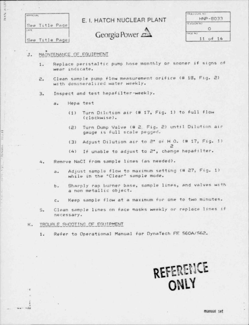
J. MAfMTENANC,E_OF FGUIPMFNT,
1. Replace peristaltic pump hose monthly or sooner if signs ofwear indicate.
2. Clean sample pump flow measurement orifice (# 18, Fig. 2)with domineralized water weekly.
3. Inspect and test hepafilter-weekly.
'a. Hepa test
(1) Turn Dilution air (# 17, Fig. 1) to full flow.
! (clockwise).
(2) Turn Dump Valve ( # 2. Fig. 2) until Dilution airgauge is full scale pegged.
~
2(3) Adjust Dilution air to 2" of H O. (# 17, Fig. 1)
j 2"
(4) If unable to adjust to 2", change hepafilter.j
4. Remove NaCI from sample lines (as needed).:-
a. Adjust sample flow to maximum setting (# 27, Fig. 1)'
while in the " Clear" sample mode.}
b. Sharply rap burner base, sample lines, and valves with2 a non metallic object,
c. Keep sample flow at a maximum for one to two minutes.
5. Clean sample lines on face masks weekly or replace lines ifnecessary.
K. TROURIE SHOOTTNG CF FOUTPMENT
1. Refer to Operational Manual for DynaTech FE 560A/562.
.
REFEREMGOMLY..
4
i .
.. . . . . ,a~
manual set-
~5 ,
M .
s . .
U11F;v AL PHOL 4 UUML NO
8 E. I. HATCH NUCLEAR PLANT HNP-8037See Title Page ""'e
Georgia Power eQO='t
A ~~
12 of 14See Title Page
..
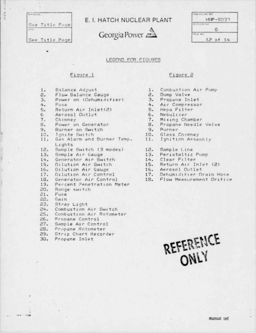
LEGFND FOR FIGilRFS.
Fiqure 1 Eigure 2
1. Balance Adjust 1. Combustion Air Pump2. Flow Dalance Gauge 2. Dump Valve3. Power on (Dehumidifier) 3. Propsne Inlet4. Fuse 4. Air Compressor5. Return Air Inlet (2) 5. Hepa Filter6 Aerosol Outlet 6. Nebulizar7. Chimney 7. Mixing Chamber8. Power on Generator 8. Propane Needle Valve
.9. Burner on Switch 9. Purner2 10. Ignite Switch 10. Glass Chimney? 11. Gas Alarm and Burner Temp. 11. Ignition Assembly
Lightsj 12. Sample Switch (3 modes) 12. Sample Line: 13. Sample Air Gauge 13. Peristaltic Pump$ 14. Generator Air Switch 14. Clear Filter
'
15. Dilution Air Switch 15. Return Air Inlet (2)16. Dilution Air Gauge 16. Aerosol Outlet.
17. Dilution Air Control 17. Dehumidifier Drain Hose18. Generator Air Control 18. Flow Measurement Orifi ce
5 19. Percent Penetration Meter| 20. Range switch|i 21. Fuse!. 22. Gain; 23. Stray Light
24. Combustion Air Switch25. Combustion Air Rotometer26. Propane Control27. Sample Air Control
| 28. Propane Rotometer29. Strip Chart Recorder30. Propane Inlet *h *
WBJOM| .
t
=.
ad-
manual set... ~a.
~
.. .
[- -
5 m~~ ., mum o
* E.1. HATCH NUCLEAR PLANT HNP-8033" ~ "vGee Title Pace
k O::ue
Georgia Power as ~ ~o
See Titla Pace 13 of 14
..
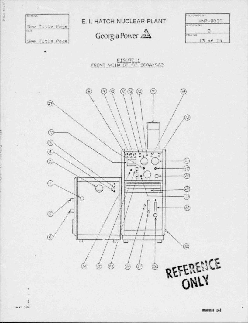
FICItRF 1
EBONT__VEIW CF FF SG.OA/Ff.2
'l (/d) // /3 /2 @ @~
. .
/5v-
| |
@ . @
, . & '
j ,
.' _ .
sqq :' a 7 2
Q4 . @'
2. .=: x1
, g'+. @.=
/ 9. 1 0 c = e' N NN
h) / \ e
['t / @\
/ 6~
,c | : @g,. O| a.
/i // /,
6 / | t | j j |u u u a
30
.
oW.
.
~l -.
. .. . .a .
manual set
m. .
: .
. ...
a w. ,_ , u um ~
* E. l. HATCH NUCLEAR PLANT HNP-8037See Title Pane -t v.u w
GeorgiaPower ob" ' ' ' O
~~
See Title Pane 14 op 34
..
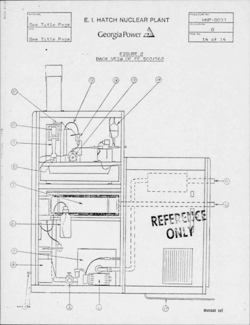
FIGt18E 2.i
BACH VEIW OF FF_5GO/GF.A>
I
/2 /B /3 /4
II -
V -'' ' N / / /wy* W
7 F .
=
3- I -. A- Te..
, w =
-g,- ,2- 2-: -- ,
=** CA _ % -,
\k a/ _r v/---
~
\~,
,_ _ _ _ _ _ _ _It,
( ,. b !_ .. h'
L__ o
|| t_______!o'
~ ~
% . - _. .. ,i.
._ 'N_ _ ' _ _ _ _ _ _ _ _ . _ _ _ _ _ _ _ .._g-g
-- .
,, .
t.
,' REFEqLmg- ,i i7pm ,, _ _ . - - - _ _ . . m ,
g(/ || OMd
-
-g
'(. s
b ,li
@ ~1 " li_
N m |I *'
.w
,N . ' >@ ~
( G_._s
,\ m '-
' i \ XU = 2-
X' iO t. I= = ]
s = r_,
' _
.' 4
~ ~ $j !. .
b & 0 /7 manual set *