emergency procedure final-1
DESCRIPTION
emTRANSCRIPT
1. Drum level dropping fast
Likely causes One of the running BFP might have tripped Sudden tripping of one or more Mills/feeder. FW control valve/scoop might have closed/stuck. Malfunction of auto control/scoop regulation. BFP recirculation valve suddenly opened or valve passing Sudden reduction of load. Tube failure in water walls. HPBP in open position for long time under full load condition Inadvertent opening of EBD & low point drains. Drum pressure very high Drum level transmitters faulty.
Plant response Drum level LOW alarm appears. BFP's scoop rises to maximum. FCV opens to 100% Boiler will trip if drum level becomes very low
Parameters of concern / Adverse Effects Drum level very low may affect natural circulation in water wall panel and if drum is empty tubes will melt in no time Deaerator level Hot well level Feed water flow Steam flow SH/RH temp
Immediate expected or desirable operator action. See that standby BFP starts on tripping of running BFP or else Manually start standby BFP when level drops to -100 mm & load the pump immediately.
Check for any malfunction of auto control like scoop/FCV not raising or recirculation open in auto, take control in to manual & regulate it
Close CBD if it is open. Close BFP RC valve MIV if heavy passing is noticed Close HPBP slowly if it is open. Reduce boiler firing when level is about -100 mm
Final Corrective Activity. Check drum level is getting stabilised. Ensure drum level controls are in auto. Check feed water flows matches with steam flow for full load, if deviation is more then check for any leak in boiler area. Ensure for the availability of standby BFP as early as possible. Check for local level gauge & transmitters. Check boiler low point drains & EBD. Check for scoop controls for any linkage failures.
2. Drum level shooting up fast
Likely causes Malfunction of feed control valve or BFP scoop. Scoop /Flow control valve might have stuck. Sudden increase of load Drum level transmitters may be faulty. Sudden increase of firing rate. Sudden opening of HPBP.
Plant response Drum level high alarm will appear. If drum level reaches very high level boiler will trip BFP scoop & FCV position reduces BFP RC valves may open
Parameters of concern / Adverse Effects Drum level very high may cause priming foaming & carry over. If Water is discharged to super heater header hammering may occur
& wet steam may enter MS line Deaerator level Hot well level Feed water flow Steam flow SH/RH temp
Immediate expected or desirable operator action. Open emergency blow down –EBD-valve Reduce HPBP valve position if it is open Reduce boiler firing If drum level is approaching trip value take drum level control on manual & regulate Reduce load for a momentso as to control the water level (if water level is due to upward load surge).
Final correction activity Check drum level is getting stabilised. Ensure drum level controls are in auto. Check feed water flow matches with steam flow. Check for stuck of feed control valves & scoop. Check the level at local, hydrostep and transmitters are matching.
3. Rapid Boiler steam pressure rise
Likely causes Corex calorific value increased drastically. Sudden loading of mill. High firing rate. Feeder hunting. Malfunction of CMC. Sudden dropping of generator load & HPBP not opened
Plant response Throttle pressure high alarm will come HP/LP bypass opens on auto. APH FG I/L O2 low alarm will appears Boiler safety valve may float. Drum level will vary.
Parameters of concern/Adverse effects. Drum pressure sudden raise may cause safety valve lifting Tube leak may start Unit load MS /RH temperature Drum level APH inlet O2 HP/LP bypass
Immediate expected or desirable operator action Take the fuel control into manual mode if it is in CMC & reduce the fuel firing. Trip the malfunctioning feeder/mill & reduce PA airflow through that mill. Check for pressure drop & if it is not holding remove the corex burners. Start standby BFP if drum level is dropping
Final correction activity Check for reseating of safety valve As soon as the pressure starts dropping, restore the correct fuel input. Stop the third running BFP and keep it in standby. Ensure drum level got stabilised. Check for closure of HP bypass. Ensure pressure is stable.
4. Rapid Boiler steam pressure decrease
Likely causes Sudden drop in corex pressure or Calorific value Tripping of mill or feeder or oil elevation Mill getting unloaded HPBP got opened Sudden rise in load. Boiler tube leakage Safety valve not closing after floating
Plant response O2 at APH inlet high alarm MS pressure will drop. Generator load will come down. Drum level will drop.
Parameters of concern/Adverse effects Drum level generator load MS pressure MS/RH temperatures APH FG inlet O2 If rate of pressure drop is more than the given saturation temp. curve boiler drum will subjected to severe thermal shock
Immediate expected or desirable operator action. Check for any mill unloading/ tripping Reduce load set point to hold the MS pressure around 110 kg/cm2. Close HPBP if it is opened Check for safety valve floating Raise boiler firing in case of mill tripping. Take oil elevation in to service if required Check boiler flame Monitor drums levels during this disturbance, if it is dropping very fast, start standby BFP.
Final correction activity. Ensure drum level is stable. If mill is unloaded stop the mill & take other mill into service. Increase to full load based on the fuel. Remove oil if it is introduced if furnace conditions are good or bright.
5. EMRV floating and resetting in succession
Likely causes Improper blow down setting for EMRV/ pressure switch malfunction Fuel in put to boiler varying continuously. Turbine control valve/HPBP valve hunting MS pressure fluctuation
Plant response Drum level will vary. EMRV open/close indication in Control room Drum pressure fluctuation Ms temp and RH temp variation. Turbine control valve may hunt due to varying throttle pressure
Parameters of concern/Adverse effects Drum level MS pressure. Ms temp and RH temp Shock to boiler component Valve may get damaged.
Immediate expected or desirable operator action Reduce the fuel firing if pressure is really high. If MS pressure is less, still EMRV is operating, keep selection switch to "OFF" so that the EMRV will not operate.
Even by putting "off ", valve is still in open condition, its manual isolation valve can be closed.
Final correction activity Ensure for proper re-seating of the valve & put back in auto.
6. RH SV floating and resetting in succession
Likely causes HP bypass opened & valve hunting LP bypass opened & valve hunting HPBP opened & LPBP not opened Improper blow down setting of Safety valve
Plant response HRH steam pressure high alarm will appear. MS and RH temp variation HRH/MS pressure variation Generator load may vary due to turbine control valve hunting
Parameters of concern/Adverse effects Drum level MS and RH pressure HRH temp Shock to boiler component
Immediate expected or desirable operator action If LP bypass not opened even with pressure more than sliding setpoint, reset LPBP trip & see LPBP is opened Take HP/LP bypass valve on manual if it is hunting in auto Reduce MS pressure, if actually high, so that HP bypass will close in auto. Reduce the turbine load until the valve resets
Final correction activity If Blowdown adjustment is required do it in the nearest available opportunity If any control is malfunctioning attend to it
7. MS temperature rising fast
Likely causes Inadequate spray due to malfunctioning of spray control valves. Excess airflow. Burner tilt stuck in up position Leakage in the spray line. Low feed water temperature. Boiler firing raised in top elevation Heavy furnace slagging Spray isolation valve in close condition
Plant response MS temperature high alarm will appear. Spray control valves will go for further opening. If temperature is very high, turbine will trip.
Parameters of concern/Adverse effects MS/RH temperatures MS temp at turbine inlet
HP exhaust temperature. Spray quantity/ FCV differential pressure. Tilt position Metal temp. raise above design value will reduce tube life drastically
Immediate expected or desirable operator action Make burner tilt fully down Take MS spray control to manual & raise spray quantity (stage -1 o/l temp should be around 450°C & stage -2 o/l temp around
505°C) Reduce firing in top elevation If rate of pressure rise is more, then pick up load if margin is there. Reduce airflow based on the O2 percentage. Check spray station is properly lined up
Final correction activity
Start soot blowing, if slagging is more Restore back the temp controls in auto if it has been taken in manual Check for any malfunction of spray control valves & isolate such type of valve. Burner tilt can be kept horizontal.
8. RH temperature rising fast
Likely causes Inadequate spray due to malfunctioning of spray control valves. Excess airflow. Burner tilt stuck in up position Leakage in the spray line. Low feed water temperature. Boiler firing raised in top elevation Heavy furnace slagging HP exhaust temp is high Spray isolation valve in close condition
Plant response RH temperature high alarm will appear. Amount of spray will rise. Turbine will trip if RH temp reaches very high
Parameters of concern/Adverse effects RH temperatures RH temp at turbine inlet HP exhaust temperature. Spray quantity/ FCV differential pressure. Tilt position Metal temp raise above design value will reduce tube life drastically
Immediate expected or desirable operator action Make burner tilt fully down Take RH spray control to manual & raise spray quantity Reduce firing in top elevation
If rate of pressure rise is more, then pick up load if margin is there. Reduce airflow based on the O2 percentage. Check spray station is properly lined up Check HP exhaust temp is normal
Final correction activity Start soot blowing if furnace slagging is there. Keep the burner tilt in horizontal condition. Restore back the control in auto if it has been taken in manual.
9. MS temperature falling fast
Likely causes Tripping of mill Sudden boiler pressure drop Malfunctioning of spray control valves. Spray station passing Less air flow Burner tilt fully down High feed water temperature Soot deposits on SH tubes
Plant response MS temperature low alarm will appear. Turbine will trip if MS temp goes very low.
Parameters of concern/Adverse effects Ms temp Spray quantity Burner tilt
Immediate expected or desirable operator action Close the spray control valves by taking it into manual. Make burner tilt upward. Check airflow &Rise if necessary. Increase firing in top elevation Reduce turbine load if pressure is dropping Close spray station Block valve/ isolation valve if control valve is passing.
Final correction activity Start LRSB operation Observe for improvement in temperature. Restore back the controls in auto (spray control) Check for any malfunction of control valve & isolate it.
10. RH temperature falling fast
Likely causes Tripping of mill Sudden boiler pressure drop Malfunctioning of spray control valves. Spray station passing Less air flow Burner tilt fully down High feed water temperature Soot deposits on RH tubes
Plant response RH temperature low alarm will appear. Turbine will trip if RH temp goes very low 450°C
Parameters of concern/Adverse effects RH temp Spray quantity Burner tilt Load
Immediate expected or desirable operator action Close the spray control valves by taking it into manual Make burner tilt upward Check airflow &Rise if necessary Increase firing in top elevation Reduce turbine load if pressure is dropping Close spray station Block valve/ isolation valve if control valve is passing.
Final correction activity
Start LRSB operation Observe for improvement in temperature. Restore back the controls in auto (spray control) Check for any malfunction of control valve & isolate it.
11. COREX VENT VALVE FAIL TO CLOSE.
(A) INDIVIDUAL CORNER VENT NOT CLOSING
LIKELY CAUSES Inadequate Air supply to the valves Command from DCS to field not extended Feedback problems in nozzle valves
PLANT RESPONSE Down stream pressure will come down as compared with the corresponding valve position.
PARAMETERS OF CONCERN Corex header pressure. CO ppm in the atmosphere.
OPERATOR ACTION Check the valve position at local. Take out pair of corresponding burners.
FINAL CORRECTIVE ACTION Remove pair of corresponding burner & rectify the problem with help of C&I.
(B) COREX C- HEADER VENT VALVE OPENED
LIKELY CAUSES
Inadequate air supply to the valves Command from DCS to field not extended
PLANT RESPONSE Corex pressure will come down at faster rate Corex leak alarm may come
PARAMETERS OF CONCERN Corex header pressure. CO ppm in the atmosphere.
OPERATOR ACTION Take out burners in pairs. Close trip valve
FINAL CORRECTIVE ACTION Find out the root cause & rectify the problem with help of maintenance.
12. COREX TRIP VALVE FAILS TO CLOSE.
LIKELY CAUSES Inst. air supply failure Mechanical failure. Command from DCS to field not extended.
PLANT RESPONSE If the trip valve has failed to close during boiler trip, the corex will vent out from the C hdr vents & chances of increase in CO
PPM will be there. Corex may also enter in the boiler if there is passing in any of the corner nozzle valves.
PARAMETER OF CONCERN CO ppm in atmosphere. Furnace draft. (If the corex trip valve has failed to close during boiler trip accompanied with the failure of closing of any corner
nozzle valves). MS pressure. (If the corex trip valve has failed to close during boiler trip accompanied with the failure of closing of any corner nozzle
valves). Furnace flame. (If the corex trip valve has failed to close during boiler trip accompanied with the failure of closing of any corner
nozzle valves).
OPERATOR ACTION Close UNIT supply goggle valve & Ensure that the C header pressure reduces to atmospheric pressure. Ensure the furnace purge cycle completion.
FINAL CORRECTIVE ACTION Find out the root cause & rectify the problem with help of maintenance.
13. HEAVY ASH BUILD UP IN ONE OF THE HOPPERS.
LIKELY CAUSES Failure to carry out ash evacuation in time. Problems with electronic controller and transformer rectifier of the fields in service. Under voltage tripping of the fields in service. Transformer protection acted of the fields in service. Choked ash lines preventing hopper from being evacuated Moist ash. Rat hole in hopper Struck up of foreign material in the conveying system Failure of heating element-ash may stick to the hopper Insufficient vacuum developed by blower.
Problem with air intake valve Insufficient loading of succeeding fields.
PLANT RESPONSE EP fields trip on low voltage. Build up to high tension emitting system, causing short circuit Buckling of collecting electrode/Dislocation Ash level high alarm will come, will trip the field Dust carry over from chimney. CEMS will indicate high SPM.
OPERATOR ACTION Check ash-handling system. Switch off the field Try to charge possible fields as early as possible Switch over to corex fuel. (If it is going to take longer period to rectify the problem). Reduce coal firing. Manual poking of hopper to be done (ensure that particular field is off) If vacuum is not developing change the blower. Switch on heaters. Check rapping frequency The ash evacuation should be continued due to gravity settlement
PARAMETERS OF CONCERN Stack emission. Tripping of field
FINAL CORRECTIVE ACTION Arrange for ash evacuation. After evacuation charge the field.

14. OIL LEVEL LOSS IN APH BEARINGS
LIKELY CAUSES Leakage in piping Leakage in drain plug, instruments, connections Leakage in threaded joints Leakage through filter vent plug Oil seal damage
PLANT RESPONSE Rapid rise in oil temperature Noise may come if bearing is damaged Bearing temp will raise. If leakage is there near the hot end, may cause fire break-out.
OPERATOR ACTION Find out the leakage point. Stop the oil pump to avoid further loss of oil. Make up the oil level in the bearing housing. Run the stand by oil pump only if the leakage point is not from the common piping. In case of any fire, extinguish it with the help of proper extinguisher at the earliest possible.
PARAMETERS OF CONCERN Oil level Oil temperature Bearing temperature.
FINAL CORRECTIVE ACTION Add oil through the dip stick hole until max oil level mark . Leakage to be arrested. Put the oil system back in to service.
15. AIR-PREHEATER MOTOR TRIPS/ AIR MOTOR DOES NOT START
A. ONE APH MOTOR TRIPS/AIR MOTOR DOES NOT START.
LIKELY CAUSES Motor may trip on overload. Power supply to the motor failed. Air motor failure or solenoid failure No compressed air available. Lube oil system fail. Some foreign material fallen on the APH & got stuck. Seal of the APH has got disturbed.
PLANT RESPONSE Rapid fall of hot air temperature on one side.
Rapid rise of gas temperature of stopped APH. Possibility of deformation of APH. Alarm at ECP/ DCS electrical motor stop- appears. Furnace draft will fluctuate due to ingress of cold FD air. Mill temp will drop as a result of drop in hot PA temperature.
OPERATOR ACTIONS Reduce boiler/generator load to 60% MCR gradually. Attempt for starting the electric motor, if the power has resumed or after resetting the over load. If the air motor has not started because of air solenoid problem open the bypass valve of the solenoid. Isolate affected air heater on the gas side first if all the attempts of starting the air motor or electric motor has failed. (Keep watch on
draft) Isolate the affected APH at airside (keep watch on total airflow) Try to rotate air heater manually. Maintain generator load depending upon the parameters of the running AH. Watch hot air temperatures to mills Cut in oil burners, when load is reduced. Reduce corex to minimum. Checks lube oil system & restore lubrication.
PARAMETERS OF CONCERN Flue gas temp at APH I/L & O/L. Furnace draft. Mill o/l temp / hot PA temperature Secondary air temperature.
FINAL CORRECTIVE ACTION After rectifying the problem of electric motor / air motor, start air / electric motor before normalizing the dampers on air/gas side. If the problem is due to stucking of foreign material, then outage may be required to remove the same.
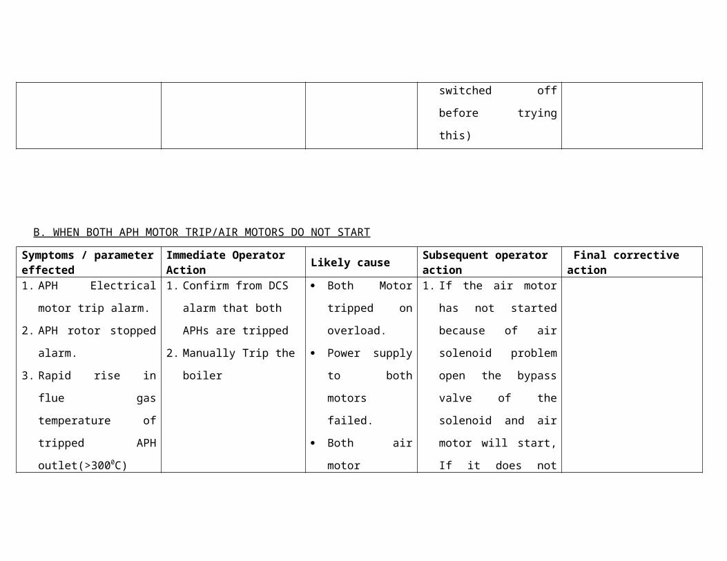
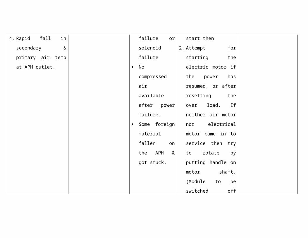
B. WHEN BOTH APH MOTOR TRIP/AIR MOTORS DO NOT START
LIKELY CAUSES Power supply failure/ motor failure. Compressed air failure
PLANT RESPONSE Rapid fall of hot air temperature Rapid increase in flue gas temperature Possible distortion in air heater rotor Air heaters A/B electrical motor stop & APH rotor stop alarm at ECP/DCS.
OPERATOR ACTION Reduce the fuel firing drastically as early as possible. Parallel attempts to be made for electric/air motor If failed to restore APH rotation within ten minutes, shut down the boiler. Manually rotate APH till alternate arrangement is made.
PARAMETERS OF CONCERN Flue gas temp at APH I/L & O/L. Furnace draft. Mill o/l temp / hot PA ,SA temperatures. Secondary air temperature
FINAL CORRECTIVE ACTION After rectifying the problem of electric motor / air motor, start air / electric motor before normalizing the dampers on air/gas side.
16. SUDDEN INCREASE IN STEAM SILICA
LIKELY CAUSES DM make water silica may be high. Condenser tube leakage. System taken into service after major over haul & maintenance.
OPERATOR ACTION Ask chemist to confirm panel instrument readings of silica by actual analysis. Increase the drum blow down. Reduce drum pressure as per the curve “ silica in boiler water/boiler pressure" taking into account solubility of silica in steam at
elevated pressures. Maintain phosphate concentration in Drum around 5ppm. If the steam quality is affected by the process within the system, shutdown the turbine & start dumping through bypass to improve
the steam quality before rolling the turbine. If steam quality cannot be improved because of the make up water faulty/ condenser tube leakage, shutdown the unit.
PARAMETERS OF CONCERN Silica concentration in drum, steam. Phosphate concentration. Drum pressure.
PLANT RESPONSE Drum silica & steam silica high alarms will appear. Silica carry over in steam>0.02ppm leads to deposits on turbine blades.
FINAL CORRECTIVE ACTION Check &Correct DM make up quality. If condenser tube leakage is there after attending only, boiler to be lighted up.
Hot blowdown is to be given to displace impure water & level to be made up with fresh DM water. After restart of the boiler, don't take condensate into the system into service until quality of condensate is satisfactory.
17. BOILER WATER pH IS FALLING FAST
LIKELY CAUSE Improper phosphate dosing make up water faulty Due to continuous passing in IBD/CBD.
PLANT RESPONSE pH low alarm will appear Leads to accelerated corrosion of boiler tubes and consequent tube failure conductivity of boiler drum also comes down
PARAMETERS OF CONCERN pH of the drum water pH of condensate. Conductivity
OPERATOR ACTIONS Increase phosphate dosing. Check for passing in CBD/IBD. Consult the chemist. Check whole regime of the system.
FINAL CORRECTIVE ACTION Find the root cause of the problem; if it is due to faulty dosing then check concentration of the dose. If it is due to passing get it
arrested. ask chemist to check DM water quality.
18. REPEATED TRIPPING OF COLLECTING RAPPING MOTORS OF ESP
LIKELY CAUSE High ash level in hoppers. Improper setting of motor overload relay
PLANT RESPONSE Inefficient ash collection in ESP. Stack SPM may increase
PARAMETERS OF CONCERN Ash level, field current,SPM
OPERATOR ACTIONS Switch off the motor supply Switch off the fields if tripping on ash level high and empty the hopper. Switch on available /stand by field in the same pass.
FINAL CORRECTIVE ACTION Switch on the field and take rapping motor into service Get over load setting checked rectify the problem.
19. AC Scanner fan tripped & DC failed to pickup
Likely causes DC fan fails to start after AC fan trip Both fan getting over load/electrical fault
Plant response Scanner air to furnace DP low alarm Scanner air fan tripped alarm Inadequate cooling of scanners may cause damage to scanner sensing element
Parameters of concern/Adverse effects
Scanner air to furnace DP low Flame scanner cooling is not taking place
Operator action Try to start fan by resetting overload relay Increase FD fan discharge pressure so that some air will always available for scanner If not happening reduce load to minimum & get the fan started at the earliest. If Scanner air fan could not be restarted even after reasonable time delay trip the boiler
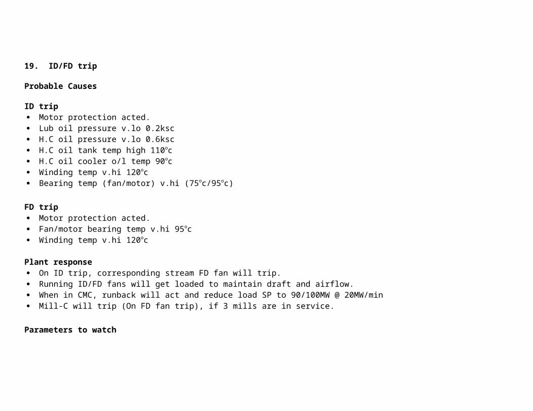
19. ID/FD trip
Probable Causes
ID trip Motor protection acted. Lub oil pressure v.lo 0.2ksc H.C oil pressure v.lo 0.6ksc H.C oil tank temp high 110oc H.C oil cooler o/l temp 90oc Winding temp v.hi 120oc Bearing temp (fan/motor) v.hi (75oc/95oc)
FD trip Motor protection acted. Fan/motor bearing temp v.hi 95oc Winding temp v.hi 120oc
Plant response On ID trip, corresponding stream FD fan will trip. Running ID/FD fans will get loaded to maintain draft and airflow. When in CMC, runback will act and reduce load SP to 90/100MW @ 20MW/min Mill-C will trip (On FD fan trip), if 3 mills are in service.
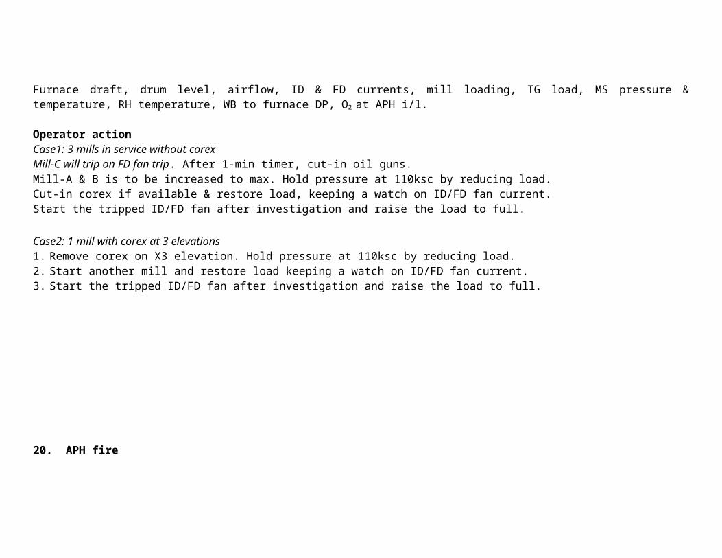
Parameters to watchFurnace draft, drum level, airflow, ID & FD currents, mill loading, TG load, MS pressure & temperature, RH temperature, WB to furnace DP, O2 at APH i/l.
Operator actionCase1: 3 mills in service without corexMill-C will trip on FD fan trip. After 1-min timer, cut-in oil guns.

Mill-A & B is to be increased to max. Hold pressure at 110ksc by reducing load.Cut-in corex if available & restore load, keeping a watch on ID/FD fan current.Start the tripped ID/FD fan after investigation and raise the load to full.
Case2: 1 mill with corex at 3 elevations1. Remove corex on X3 elevation. Hold pressure at 110ksc by reducing load.2. Start another mill and restore load keeping a watch on ID/FD fan current.3. Start the tripped ID/FD fan after investigation and raise the load to full.
20. APH fire
Likely causes Defective oil burner, leading to deposition of un burnt oil particles on APH heating elements. Soot deposit on APH heating element In effective APH soot blowing. Guide bearing oil leakage in to APH.
Plant response Flue gas/ secondary air temp high alarm should come(presently not commissioned) Flue gas temp after Air heater rises sharply Sec air and primary air temp after APH rises sharply. At worst case APH may get damaged

Parameters of concern. Flue gas temp after Air heater Sec air and primary air temp after APH Damage to APH
Immediate expected or desirable operator action. Reduce boiler load Close Flue gas inlet damper Close PA &Secondary air side inlet & outlet dampers Open APH hopper drain plug Open cold end side & hot end side hydrant valve and quench fire
Final correction activity. Stop the oil guns with smoky flame if they are in service. Isolate APH and open for inspection if fire is extensive
21. FIRE NEAR MILL AREA
LIKELY CAUSES High mill outlet temp. Running mill with less air flow for long time can cause coal accumulation in mill discharge pipe & cause fire High % of volatile mater in coal If mill rejects are more & not removed regularly may cause fire in rejects chamber. Tramp Iron Gate stuck in close position, causing fire in rejects chamber. Coal accumulation in hot air duct Fire conveyed from bunker coal
PLANT RESPONSE : Mill out let temp. high alarm Mill DP & air flow , current variation. Fire coming from reject hopper Red hot mill body/ reject chamber
Parameters of concern Mill puffing Mill o/l temp. Air i/l temp. Mill airflow. Mill DP Mill rejects.
Immediate /expected or desirable operator action Reduce hot air flow to mill & continue to run with more coal. Mill rejects hopper to be cleared If fire is not reduced stop feeder & open Mill inheriting steam valve & Hydrant water valve Stop Mill & release for clearing after fire is quenched
Final correction activity Inspect mill internals and feeder for healthiness.
22. LRSB NOT RETRACTED
LIKELY CAUSES Forward/Reverse motor trip Lance jammed after advancing LRSB clutch de coupled after advancing Electrical supply failure during operation Chain broken.
PLANT RESPONSE
Soot blower not retracted alarm Soot blower overload acted alarm
Parameters of concern Steam jet hitting boiler tubes LRSB getting damaged
Immediate /expected or desirable operator action Reset the module & give retract command from local push button. If it fails to retract even after module is reset, switch-off the
module. Reduce soot blower header pressure to 3- 4Ksc. Disengage the clutch and try to retract manually from handle. If it is retracting do not release handle in the middle ( If handle is to be
released in the middle, first engage the clutch & then only release) . Inform maintenance if it is not retracting manually also. Try retracting with additional assistance for max. one hour. If it could not be retracted within 1hour, reduce pressure to “0” ksc & try again. Still if it is not retracting ask maintenance to insert dummy in steam supply line flange so that other blower operation can be carried
out.
Final correction activity If the lance is deformed change with new one
23. FIRE IN ESP
LIKELY CAUSES OIL/soot deposit on ESP fields Very high un burnt in fly ash & hopper heating element Not switching off ESP transformer fire
PLANT RESPONSE ESP transformer trip. Furnace Draft variation
Parameters of concern ESP O/L temperature ID fan loading Furnace Draft Damage to ESP
Immediate /expected or desirable operator action Trip ESP field Isolate the power supply of all related ESP pass/field. If fire is outside ESP, use extinguisher & douse the fire. If it is inside ESP reduce unit load & close ESP inlet & outlet gate. Inform fire man

Open ESP man holes Open ESP ash hopper drain plugs/man hole Quench the fire with fire hydrant water
Final correction activity Identify the reason and rectify it.
26. ONE OF THE TURBINE CONTROL VALVE FAIL TO CLOSE
A. Symptom /parameter effected
While reducing load, it will not reduce below certain MW even if load set point is less.
Stuck Valve position feed back will show open position control room whereas other valve will go for close.
High speed control acting.
B. Likely cause
Valve mechanically stuck.
Trip mechanism not working.
Oil not getting drained from actuator.
C. Operator action
Immediate action
Reduce turbine load to 100MW if unit is in service.
If turbine has tripped. close MS1.2.3 &4 & depressurise MS & RH line.
Open corresponding MAL drain before & after control valve(Partially).
Subsequent action If valve has stuck. Reduce boiler pressure & shut down the unit for attending the problem.
Final corrective action
Start turbine only after valve problem is attended.
27. ONE PHASE OF THE GT POLES FAIL TO OPEN AFTER UNIT TRIP
A. Symptom /parameter effected
Pole Discrepancy alarm will come.
LBB protection will trip all the breaker connected to that bus.
TG speed does not drop after trip.
TG draws current from grid (reverse power).
Negative sequence current in Generator.
LP exhaust temperature may shoot up.
B. Likely cause
Breaker contact mechanically stuck.
C. Operator action
Immediate action
Trip all the 220 kV breaker connected to the particular bus including bus coupler.(If LBB not acted).
Trip field breaker manually. If it did not opened.
Open isolators of GT breaker.
Subsequent action
Normalise supply by charging Lines .STs and Bus coupler.
Final corrective action
Attend GT breaker before restarting Turbine.
28. SCANNER FAN TRIPPED & DC FAN FAIL TO START
A. Symptom /parameter effected
Scanner air to furnace DP low alarm. Scanner air fans tripped alarm.
B. Likely cause
Dc fan fails to start after AC fan trips. Both fan getting over load/electrical fault.
C. Operator action
Immediate action
Trip the boiler
+
Subsequent action
Try to start fan by resetting overload relay. Increase FD fan discharge pressure so that some air will always available for scanner. If not happening reduce load to minimum & get the fan started at the earliest. If Scanner air fan could not be restarted even after reasonable time delay trip the boiler.
Final corrective action
Lightup boiler only after starting scanner air fan.
29. HIGH DIFFERENTIAL EXPANSION IN TURBINE
A. Symptom /parameter effected
Difference between shaft & casing expansion more than normal.
Change in axial shift.
High turbine vibration.
B. Likely cause
Positive differential expansion.
More than rated steam pressure & temp. for rolling.
Inadequate soaking during rolling.
Too fast load pickup of load.
Sudden raise in MS/RH temp.
Casing not moving freely over its slide/ restriction for casing expansion.
High gland steam temperature.
Improper drain operation.
Negative differential expansion
Less than rated steam pressure & temperature for rolling.
Sudden drop in MS /RH temperature.
Improper drain operation.
Wet steam entry in to turbine.
C. Operator action
Immediate action
Positive differential expansion
Reduce steam temp if it is more.
Bring machine to soaking speed if it is during rolling.
Reduce turbine loading if it is after synchronisation.
Check and control gland steam temperature.
Check MAL drains are operating properly.
Negative differential expansion
Increase steam temperature if it is less.
increase turbine load if it is after synchronisation.
Check MAL drains are working properly.
Check gland steam temperature.
Check MAL drains are operating properly.
Subsequent action
Maintain steam temperature steady.
Final corrective action
30. TURBINE BEARING TEMPERATURE RAISING FAST
A. Symptom /parameter effected
Turbine/generator bearing temp. high alarm.
Lub oil return line oil temp. gauge showing more than normal.
Turbine oil cooler inlet/outlet temp. more than normal.
Change in turbine vibration pattern.
B. Likely cause
ACW pump tripped or ACW to lub oil cooler not charged after synchronisation.

High lube oil inlet temperature.
Bearing failure.
Thermostatic valve failure.
Inadequate lub oil flow or pressure.
Excessive bearing vibration.
High axial thrust.
Lub oil cooler not vented properly.
C. Operator action
Immediate action
Trip the turbine if bearing temp reaches 1200C(atleast 2 indications in metal temp overview screen).
If temp is with in 1200C then try the Subsequent action.
Subsequent action
Check lube oil flow & pressure to bearing.
Check Lub oil cooler is charged on ACW side & ACW flow is adequate.
Check return oil temp from each bearing.
Verify babit temperature by other means (to rule out faulty measurement)
If thrust bearing temperature is increasing check for axial shift.
Start Standby AOP if oil pressure is low.
Vent lub oil cooler properly.
Final corrective action
Find out reason for bearing temp raise.
31. TURBINE VIBRATION SHOOTS UP
A. Symptom /parameter effected
Turbine bearing/shaft vibration high alarm.
Turbine will trip if shaft vibration reaches trip value.
B. Likely cause
Turbine bearing damage.
Rotor eccentricity high/ Shaft distortion.
Turbine blade damage.
Turbine glands rubbing.
Sudden change in steam inlet temperature.
Lube oil temperature too low.
Uneven cylinder expansion/restriction for expansion.
Foundation bolts loose.
Alignment/centering problems.
Change in axial shift.
Sudden MVAR load change.
Improper drain Operation
High grid frequency
Machine coasting down rate too slow after trip.
C. Operator action
Immediate action
Reduce turbine load by load limiter and trip the machine if bearing vibration is >11mm/sec(for Brg No. 6 >18mm/sec.
Subsequent action.
Check locally whether vibration is actually high.
Listen to bearing sounds using a vibration sensing stick.
Maintain steam parameters normal.
Check lube oil pressure and after cooler temperature.
Check any sudden MVR change is there.
Wait for frequency change.
Trip the machine if it does not trip on high vibration.
Final corrective action
32. TURBINE STARTS ROLLING ON ESV OPENING
A. Symptom /parameter effected
Turbine speed may rise without giving command for rolling.
B. Likely cause

Control valve passing.
Control valve stuck in open position.
C. Operator action
Immediate action
Close ESV by tripping turbine.
Check whether control valves are fully closed (in DCS as well as local).
Check for the EHTC output (has to be zero).
Subsequent action
If all rolling criteria are ok and if only minor passing only is there and speed is reaching to say 800rpm roll to 3000rpm if it is a
hot startup.
Final corrective action
Attend valve problem in nearest shut down.
33. HPBP OIL LINE LEAK
A. Symptom /parameter effected
Oil leak noticed by personnel. HPBP oil pump continuously running. HPBP oil pressure low alarm. HPBP valve creep opening without open signal.
B. Likely cause
Oil leaking from ferules. Servo valves leaking. Flexible hoses bursting out.
C. Operator action
Immediate action
Isolate leaking oil line/valve.
Switch off HPBP oil pump supply.
Isolate spray line MIV if leak is in spray line.
Subsequent action
If main valve creeping is started due to loss of oil pressure then reduce turbine load slowly to 60 MW.
Bring down boiler pressure to 85Ksc. and get the leak attended.
Trip boiler if HPBP downstream steam temp. could not be maintained.
Close MS-1.2.3 & 4 and depressurise MS line in that case.
Final corrective action
If leak is attended charge the line slowly and raise the load
If leak could not be attended trip the boiler after reducing load.
34. CONTROL OIL LINE LEAK
A. Symptom /parameter effected
Oil leak noticed by personnel. Control oil tank level low alarm. Control oil pressure dip. Oil leak detected from LPBP/IPSV tray switch. Oil leak detected from Control oil skid tray switch.
B. Likely cause
Oil leaking due to O ring failure. Servo valves leaking. Joint leak/welding failure. Excessive control oil pressure.
C. Operator action
Immediate action
Close isolation valve (at control oil skid) of leaking line if leak is in individual lines.
Reduce turbine load to 100MW.if any turbine valve has closed.
Open corresponding MAL valve partially.
Change over to standby pump if leak is in pumping unit.
If leak is in common block & leak does not stop after change over, reduce turbine load & trip Control oil Pumps immediately.
Subsequent action
Inform fireman and keep fire extinguisher ready if oil is spilled over valve body or steam line.
After attending leaky point charge line very slowly.
Final corrective action
Arrange to clean leaked out oil.
35. WATER/OIL DETECTED IN GENERATOR CASING.
A. Symptom /parameter effected
Liquid in Generator casing alarm. TG trip on LLD sensing level in Generator bushing top.
B. Likely cause
H2 cooler leakage. DPRV malfunctioning and maintaining higher DP. Defective seals component and oil entering generator casing.
C. Operator action
Immediate action
Open LLD drains after isolation and empty it. See whether oil or water is coming. After draining, normalise and wait for further liquid level sensing. If water is coming reduce generator load & isolate one hydrogen cooler & find out leaky cooler . If oil is coming see seal oil to H2 DP is normal.
Subsequent action
If liquid from drain is continuos plan for unit shut down. If liquid is because of DPR malfunctioning get it attended.
Final corrective action
Find out reason for liquid entry in casing and rectify it.
36. WATER HAMMER IN PIPELINE
B. Symptom /parameter effected
Abnormal / intermittent sound in pipe line. Pipeline. Hanger or supporting structure damages. To & pro movement of pipeline.
B. Likely cause
Proper charging procedure not followed.
Sudden entry of steam into water lines.
Sudden entry of steam into improperly drained pipelines.
Improper warm up during charging steam lines.
Faulty drain traps or ill designed drain valves.
Sudden opening of high pressure valves.
C. Operator action
Immediate action
Cut off steam supply to the line in which hammering is occurring.
Subsequent action
Open drains & trap bypass valves of that line.
Wait for full draining/proper warm up.
Slowly open valve and allow steam to come out of drains.
Allow system pressure to build up.
Close drains & put trap in to service.
If it is a water line ensure no steam is entering pipe line.
Final corrective action
Follow proper charging procedure.
37. COREX GAS LEAK
Symptom /parameter effected
Alarm at local / DCS will come depending upon location of leak.( 08 static CO detector in blower area, 8 CO detector & 8 H 2 detector
in different elevation on both the boiler & 01 detector in control room AC duct are connected to DCS system in Control room).
Lamp indication with hooter near DM plant water tanks
For > 50 ppm - orangeFor > 100 ppm - red
In addition Siren will be activated from control room for corex leak emergency.
B. Likely cause
Corex leak due to seal pot water seal breaking
Flange. valve gland leakage.
Passing of valves.
Explosion in pipe line.
Leakage from adjacent steel plant process
Major leakage can occur in the unlikely event of natural calamities such as earthquake etc.
C. Operator action
Check CO concentration with portable detectors and confirm with that of control room indications.
If the CO-detected by permanent / portable detectors is reading 200ppm and above, effect local area evacuation and parallel
start reduction of corex in the corresponding unit (if the leakage is sensed in blower area reduction to be done in both the
units). If greater than 400ppm for 15 min, stop A/C plant and remove corex elevation of the corresponding unit. (if the
leakage is sensed in blower area remove the corex completely in both the unit & close the bypass goggle valve and JVSL
double gate valve). And if greater than 500ppm for 30 min, declare emergency by actuating siren for totally evacuation of the
personnel.
Inform safety officer / fire control room in any of the above case.
Check for leakage, all the source of ignition should be kept away, Self-contained breathing apparatus (SCBA) to be used
while checking and attending leak.
In case fire takes place during leak, first the pressure in the supply line should be reduced to shorten the flame & then the fire
should be extinguished. Only after the fire is extinguished, the main gas should be closed completely. Never close the main
valve, when the fire is still there and the pressure in the gas main should not be reduced below 100mmwc.
In case anyone notices an emergency type situation, shift-in-charge should immediately reach the location of emergency with
necessary safety gadgets and assess the situation. He will declare the emergency by informing control room to send coded
siren (15 seconds on & off for 3 minutes). At the same time he will decide about the emergency shut down of the plant
Perform the head count at the assembly point (Old admin. Bldg).
All clear signals (2 min- continuous) siren to be raised if the declarer of emergency clears the emergency after attending the
leakage.
Subsequent action
Purge the corex system with nitrogen & achieve the co ppm less than allowable range of 50 ppm
Find out the exact location of the leakage.
Arrest the leakage point & check for leakage
Final corrective action
Take corex in to service only after clearance from safety dept.
38. COREX VENT VALVE FAIL TO CLOSE
A. Symptom /parameter effected
Valve fail to close alarm Corex leak alarm Valve close indication not coming in DCS
B. Likely cause
No or inadequate air supply to the valve actuator.
Command from DCS to field not extended.
Valve mechanically stuck in open condition.
C. Operator action
Immediate action
If C- header vent valve fails to close. then remove corex totally from that unit.
Ensure Nitrogen purge valve is open.
If it is corner vent valve. remove that corex pair from service.
Subsequent action
Check instrument air supply is normal to valve actuator.
Arrange to get vent valve closed from maintenance.
Final corrective action
Take corex in to service only after the satisfactory valve stroking
39. COREX TRIP VALVE FAILS TO CLOSE.
A. Symptom /parameter effected
Valve fail to close alarm. Corex leak alarm. Valve close indication not coming in DCS.
B. Likely cause
Valve Mechanically stuck.
Command from DCS to field not extended.
C. Operator action
Immediate action
Ensure all corner nozzle valves are closed.
Close corex control valve.
Close UNIT supply goggle valve and purge supply line & C header with N2.
Subsequent action
Final corrective action
Take corex in to service only after the valve is made operational.
Emergency Procedure
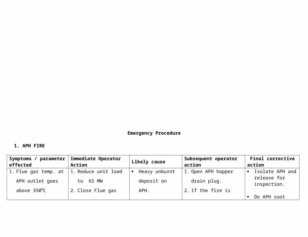
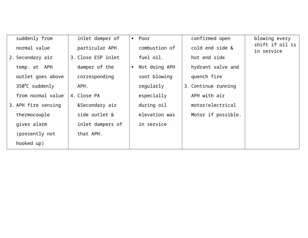
1. APH FIRE
Symptoms / parameter effected
Immediate Operator Action
Likely causeSubsequent operator action
Final corrective action
1. Flue gas temp. at APH
outlet goes above
3500C suddenly from
normal value
2. Secondary air temp. at
APH outlet goes above
3500C suddenly from
normal value
3. APH fire sensing
thermocouple gives
alarm (presently not
hooked up)
1. Reduce unit load to 65
MW
2. Close Flue gas inlet
damper of particular
APH.
3. Close ESP inlet damper
of the corresponding
APH.
4. Close PA &Secondary
air side outlet & inlet
dampers of that APH.
Heavy unburnt
deposit on APH.
Poor combustion of
fuel oil.
Not doing APH soot
blowing regularly
especially during oil
elevation was in
service
1. Open APH hopper drain
plug.
2. If the fire is confirmed
open cold end side & hot
end side hydrant valve
and quench fire
3. Continue running APH
with air motor/electrical
Motor if possible.
Isolate APH and release for inspection.
Do APH soot blowing every shift if oil is in service
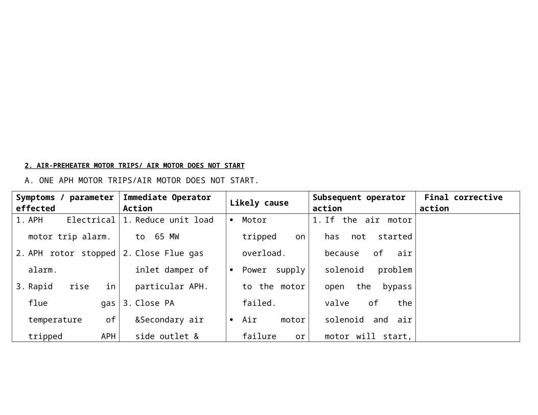
2. AIR-PREHEATER MOTOR TRIPS/ AIR MOTOR DOES NOT START
A. ONE APH MOTOR TRIPS/AIR MOTOR DOES NOT START.
Symptoms / parameter effected
Immediate Operator Action
Likely causeSubsequent operator action
Final corrective action
1. APH Electrical motor
trip alarm.
2. APH rotor stopped
alarm.
3. Rapid rise in flue gas
temperature of tripped
1. Reduce unit load to 65
MW
2. Close Flue gas inlet
damper of particular
APH.
3. Close PA &Secondary
air side outlet & inlet
Motor tripped on
overload.
Power supply to
the motor failed.
Air motor failure
or solenoid
1. If the air motor has not
started because of air
solenoid problem open
the bypass valve of the
solenoid and air motor
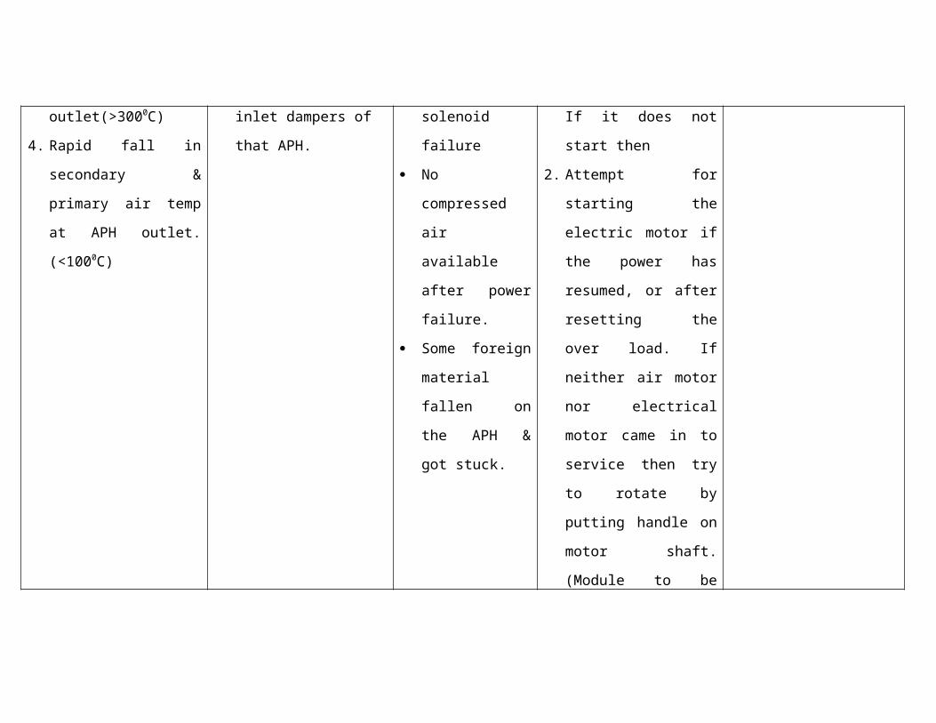
will start, If it does not
APH outlet(>3000C)
4. Rapid fall in secondary
& primary air temp at
APH outlet.(<1000C)
dampers of that APH. failure
No compressed
air available after
power failure.
Some foreign
material fallen on
the APH & got
stuck.
start then
2. Attempt for starting the
electric motor if the
power has resumed, or
after resetting the over
load. If neither air motor
nor electrical motor
came in to service then
try to rotate by putting
handle on motor shaft.
(Module to be switched
off before trying this)
B. WHEN BOTH APH MOTOR TRIP/AIR MOTORS DO NOT START
Symptoms / parameter effected
Immediate Operator Action
Likely causeSubsequent operator action
Final corrective action
1. APH Electrical motor
trip alarm.
2. APH rotor stopped
1. Confirm from DCS
alarm that both APHs
are tripped
Both Motor
tripped on
overload.
1. If the air motor has not
started because of air
solenoid problem open
alarm.
3. Rapid rise in flue gas
temperature of tripped
APH outlet(>3000C)
4. Rapid fall in secondary
& primary air temp at
APH outlet.
2. Manually Trip the boiler Power supply to
both motors
failed.
Both air motor
failure or
solenoid failure
No compressed
air available after
power failure.
Some foreign
material fallen on
the APH & got
stuck.
the bypass valve of the
solenoid and air motor
will start, If it does not
start then
2. Attempt for starting the
electric motor if the
power has resumed, or
after resetting the over
load. If neither air motor
nor electrical motor
came in to service then
try to rotate by putting
handle on motor shaft.
(Module to be switched
off before trying this)
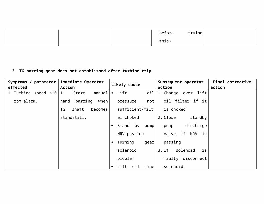
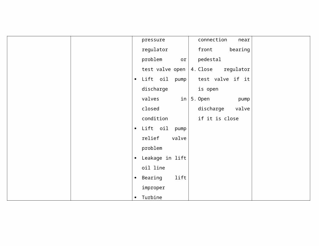
3. TG barring gear does not established after turbine trip
Symptoms / parameter effected
Immediate Operator Action
Likely causeSubsequent operator action
Final corrective action
1. Turbine speed <10 rpm
alarm.
1. Start manual hand
barring when TG shaft
becomes standstill.
Lift oil pressure not
sufficient/filter
choked
Stand by pump NRV
passing
Turning gear
solenoid problem
Lift oil line pressure
regulator problem or
test valve open
Lift oil pump
discharge valves in
closed condition
Lift oil pump relief
valve problem
Leakage in lift oil
line
Bearing lift improper
Turbine internals
rubbing
1. Change over lift oil filter
if it is choked
2. Close standby pump
discharge valve if NRV
is passing
3. If solenoid is faulty
disconnect solenoid
connection near front
bearing pedestal
4. Close regulator test
valve if it is open
5. Open pump discharge
valve if it is close
Hydro motor
problem
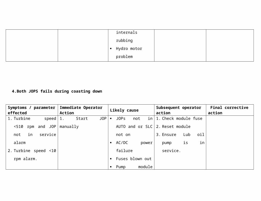
4.Both JOPS fails during coasting down
Symptoms / parameter effected
Immediate Operator Action
Likely causeSubsequent operator action
Final corrective action
1. Turbine speed <510
rpm and JOP not in
service alarm
2. Turbine speed <10 rpm
alarm.
1. Start JOP manually JOPs not in AUTO
and or SLC not on
AC/DC power failure
Fuses blown out
Pump module
problem
Module tripping on
overload
Pump mechanical
damage
1. Check module fuse
2. Reset module
3. Ensure Lub oil pump is
in service.

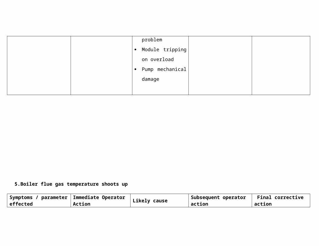
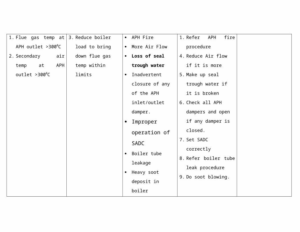
5.Boiler flue gas temperature shoots up
Symptoms / parameter effected
Immediate Operator Action
Likely causeSubsequent operator action
Final corrective action
1. Flue gas temp at APH
outlet >3000C
2. Secondary air temp at
APH outlet >3000C
3. Reduce boiler load to
bring down flue gas
temp within limits
APH Fire
More Air Flow
Loss of seal trough
water
Inadvertent closure
of any of the APH
inlet/outlet damper.
Improper
operation of
1. Refer APH fire
procedure
4. Reduce Air flow if it is
more
5. Make up seal trough
water if it is broken
6. Check all APH dampers
and open if any damper
is closed.
7. Set SADC correctly
SADC
Boiler tube leakage
Heavy soot deposit in
boiler
8. Refer boiler tube leak
procedure
9. Do soot blowing.
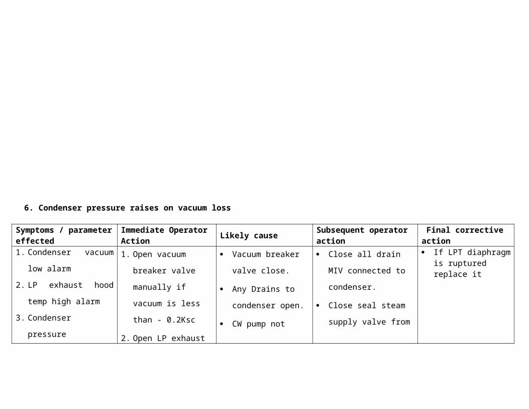
6. Condenser pressure raises on vacuum loss
Symptoms / parameter effected
Immediate Operator Action
Likely causeSubsequent operator action
Final corrective action
1. Condenser vacuum low
alarm
2. LP exhaust hood temp
high alarm
3. Condenser pressure
1. Open vacuum breaker
valve manually if
vacuum is less than -
0.2Ksc
2. Open LP exhaust
Vacuum breaker
valve close.
Any Drains to
condenser open.
CW pump not
Close all drain MIV
connected to
condenser.
Close seal steam
supply valve from
If LPT diaphragm is ruptured replace it
Transmitter showing
+ve value
hood spray main/
bypass valve if
exhaust hot temp is
>900C
running.
Seal steam supply
not cut off.
LPBP valve drift
open.
PRDS
Depressurise MS &
HRH lines by opening
MS drain to atmosphere
& HRH vent
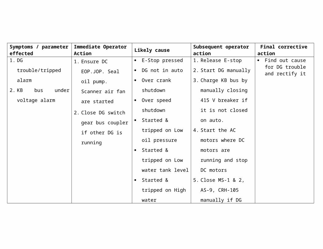
7. Emergency DG not starting after Blackout
Symptoms / parameter effected
Immediate Operator Action
Likely causeSubsequent operator action
Final corrective action
1. DG trouble/tripped
alarm
1. Ensure DC EOP.JOP.
Seal oil pump.
E-Stop pressed
DG not in auto
1. Release E-stop
2. Start DG manually
Find out cause for DG trouble and rectify it
2. KB bus under voltage
alarm
Scanner air fan are
started
2. Close DG switch gear
bus coupler if other
DG is running
Over crank shutdown
Over speed
shutdown
Started & tripped on
Low oil pressure
Started & tripped on
Low water tank level
Started & tripped on
High water
temperature
3. Charge KB bus by
manually closing 415 V
breaker if it is not
closed on auto.
4. Start the AC motors
where DC motors are
running and stop DC
motors
5. Close MS-1 & 2, AS-9,
CRH-105 manually if
DG supply is not
available
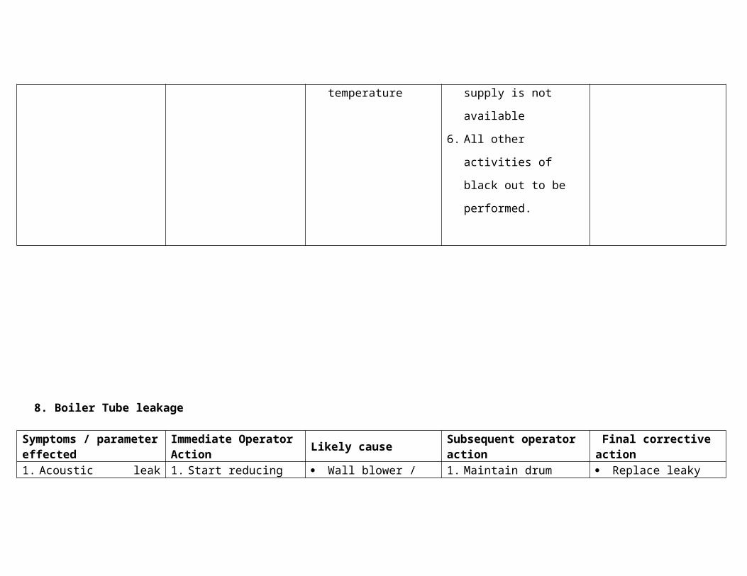
6. All other activities of
black out to be
performed.
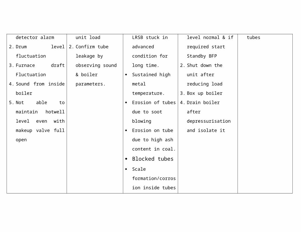
8. Boiler Tube leakage
Symptoms / parameter effected
Immediate Operator Action
Likely causeSubsequent operator action
Final corrective action
1. Acoustic leak detector
alarm
2. Drum level fluctuation
3. Furnace draft
Fluctuation
4. Sound from inside
boiler
5. Not able to maintain
hotwell level even with
makeup valve full open
1. Start reducing unit
load
2. Confirm tube leakage
by observing sound &
boiler parameters.
Wall blower / LRSB
stuck in advanced
condition for long
time.
Sustained high metal
temperature.
Erosion of tubes due
to soot blowing
Erosion on tube due
to high ash content in
coal.
Blocked tubes
Scale
formation/corrosion
inside tubes
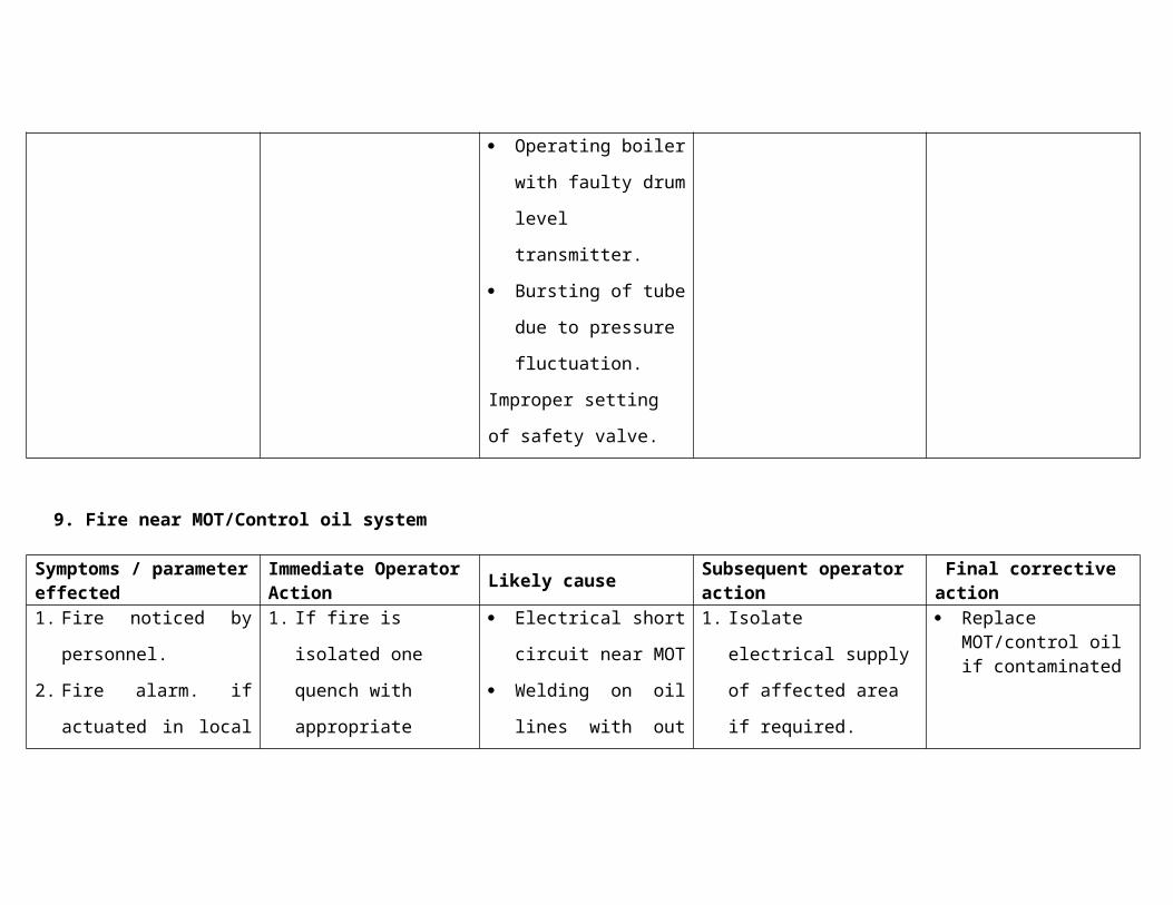
Operating boiler with
1. Maintain drum level
normal & if required
start Standby BFP
2. Shut down the unit after
reducing load
3. Box up boiler
4. Drain boiler after
depressurisation and
isolate it
Replace leaky tubes
faulty drum level
transmitter.
Bursting of tube due
to pressure
fluctuation.
Improper setting of
safety valve.
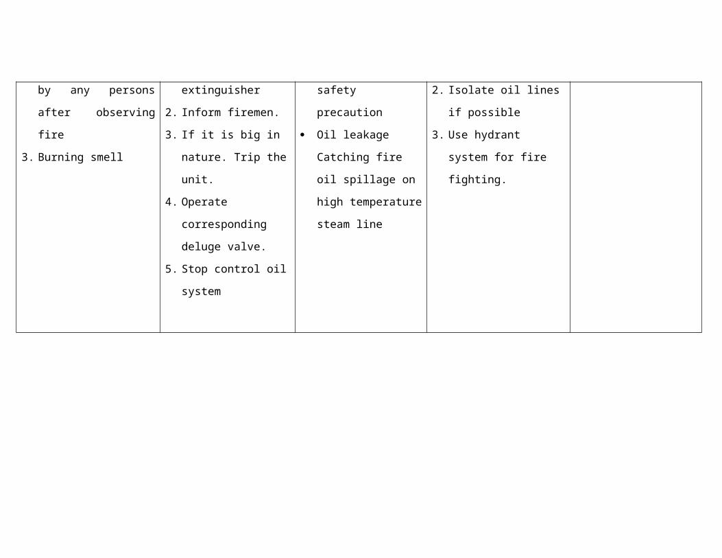
9. Fire near MOT/Control oil system
Symptoms / parameter effected
Immediate Operator Action
Likely causeSubsequent operator action
Final corrective action
1. Fire noticed by
personnel.
2. Fire alarm. if actuated
in local by any persons
after observing fire
3. Burning smell
1. If fire is isolated one
quench with
appropriate
extinguisher
2. Inform firemen.
3. If it is big in nature.
Trip the unit.
4. Operate
corresponding deluge
valve.
Electrical short circuit
near MOT
Welding on oil lines
with out safety
precaution
Oil leakage Catching
fire oil spillage on
high temperature
steam line
1. Isolate electrical supply
of affected area if
required.
2. Isolate oil lines if
possible
3. Use hydrant system for
fire fighting.
Replace MOT/control oil if contaminated
5. Stop control oil
system
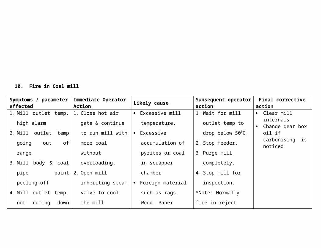
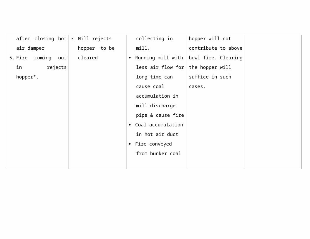
10.Fire in Coal mill
Symptoms / parameter effected
Immediate Operator Action
Likely causeSubsequent operator action
Final corrective action
1. Mill outlet temp. high
alarm
2. Mill outlet temp going
out of range.
1. Close hot air gate &
continue to run mill
with more coal without
overloading.
Excessive mill
temperature.
Excessive
accumulation of pyrites
1. Wait for mill outlet
temp to drop below
500C.
2. Stop feeder.
Clear mill internals Change gear box oil
if carbonising is noticed
3. Mill body & coal pipe
paint peeling off
4. Mill outlet temp. not
coming down after
closing hot air damper
5. Fire coming out in
rejects hopper*.
2. Open mill inheriting
steam valve to cool
the mill
3. Mill rejects hopper to
be cleared
or coal in scrapper
chamber
Foreign material such
as rags. Wood. Paper
collecting in mill.
Running mill with less
air flow for long time
can cause coal
accumulation in mill
discharge pipe &
cause fire
Coal accumulation in
hot air duct
Fire conveyed from
bunker coal
3. Purge mill completely.
4. Stop mill for
inspection.
*Note: Normally fire in
reject hopper will not
contribute to above bowl
fire. Clearing the hopper
will suffice in such cases.
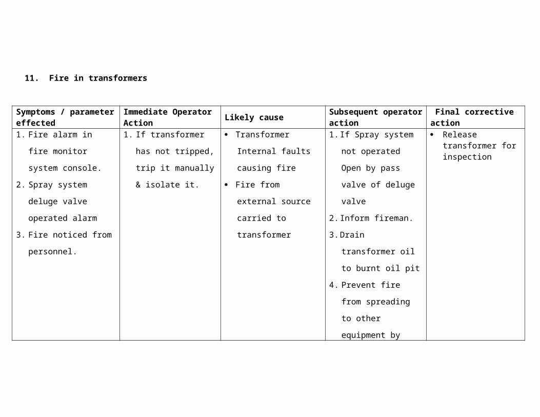
11.Fire in transformers
Symptoms / parameter effected
Immediate Operator Action
Likely causeSubsequent operator action
Final corrective action
1. Fire alarm in fire
monitor system
console.
2. Spray system deluge
valve operated alarm
3. Fire noticed from
personnel.
1. If transformer has not
tripped, trip it
manually & isolate it.
Transformer Internal
faults causing fire
Fire from external
source carried to
transformer
1. If Spray system not
operated Open by
pass valve of deluge
valve
2. Inform fireman.
3. Drain transformer oil
to burnt oil pit
4. Prevent fire from
spreading to other
equipment by fire
fighting measures
Release transformer for inspection
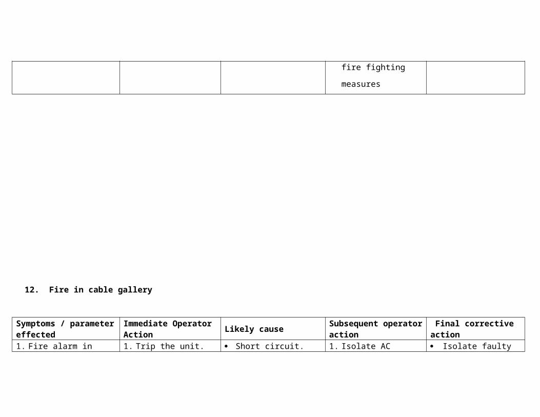
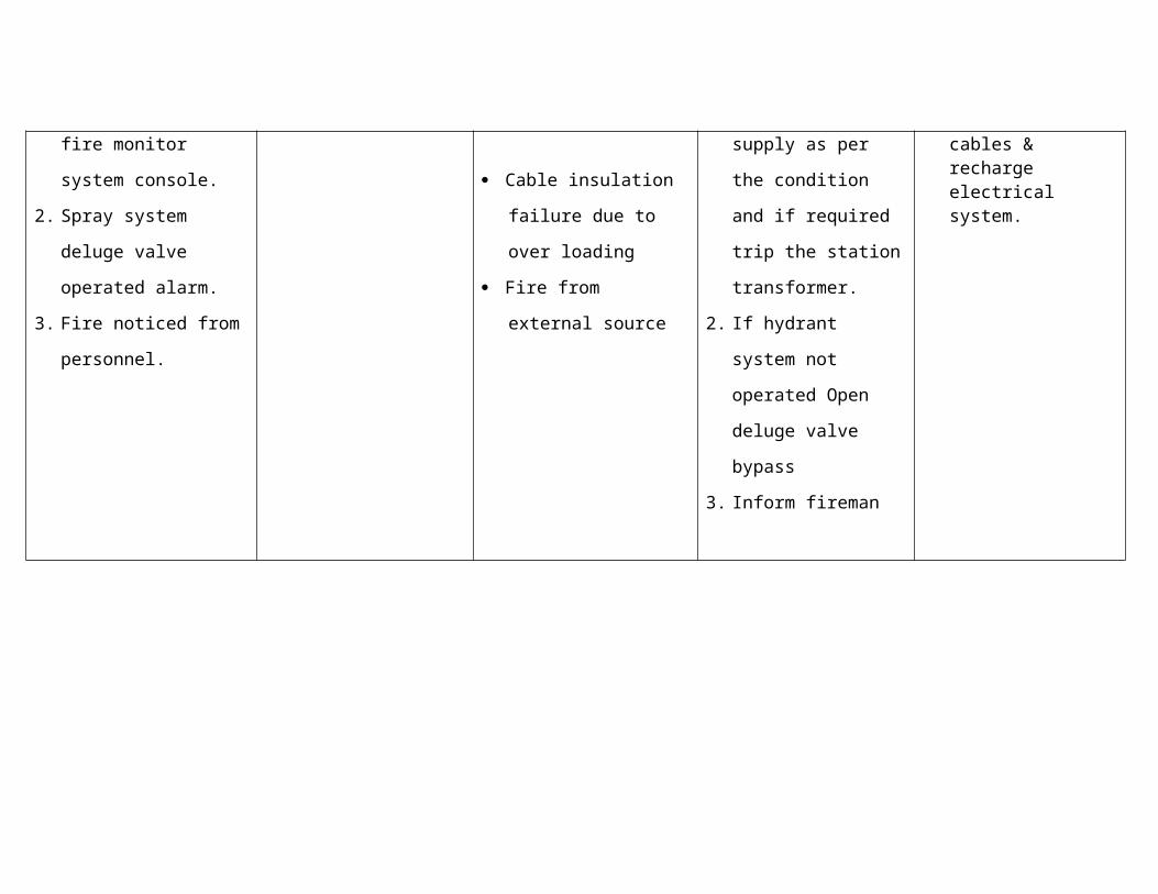
12.Fire in cable gallery
Symptoms / parameter effected
Immediate Operator Action
Likely causeSubsequent operator action
Final corrective action
1. Fire alarm in fire
monitor system
console.
2. Spray system deluge
valve operated alarm.
3. Fire noticed from
personnel.
1. Trip the unit. Short circuit.
Cable insulation failure
due to over loading
Fire from external
source
1. Isolate AC supply as
per the condition and
if required trip the
station transformer.
2. If hydrant system not
operated Open deluge
valve bypass
3. Inform fireman
Isolate faulty cables & recharge electrical system.
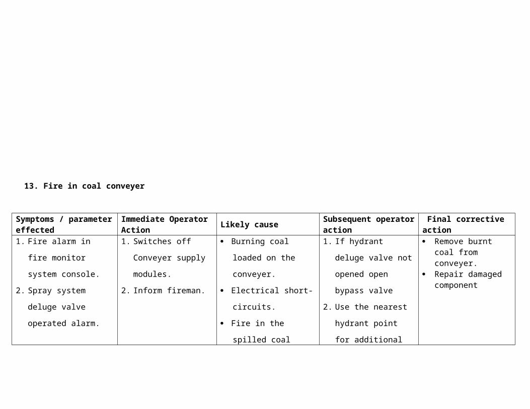
13. Fire in coal conveyer
Symptoms / parameter effected
Immediate Operator Action
Likely causeSubsequent operator action
Final corrective action
1. Fire alarm in fire
monitor system
console.
2. Spray system deluge
valve operated alarm.
3. Fire noticed from
personnel
1. Switches off Conveyer
supply modules.
2. Inform fireman.
Burning coal loaded on
the conveyer.
Electrical short-circuits.
Fire in the spilled coal
around conveyer.
1. If hydrant deluge
valve not opened
open bypass valve
2. Use the nearest
hydrant point for
additional spray
Remove burnt coal from conveyer.
Repair damaged component
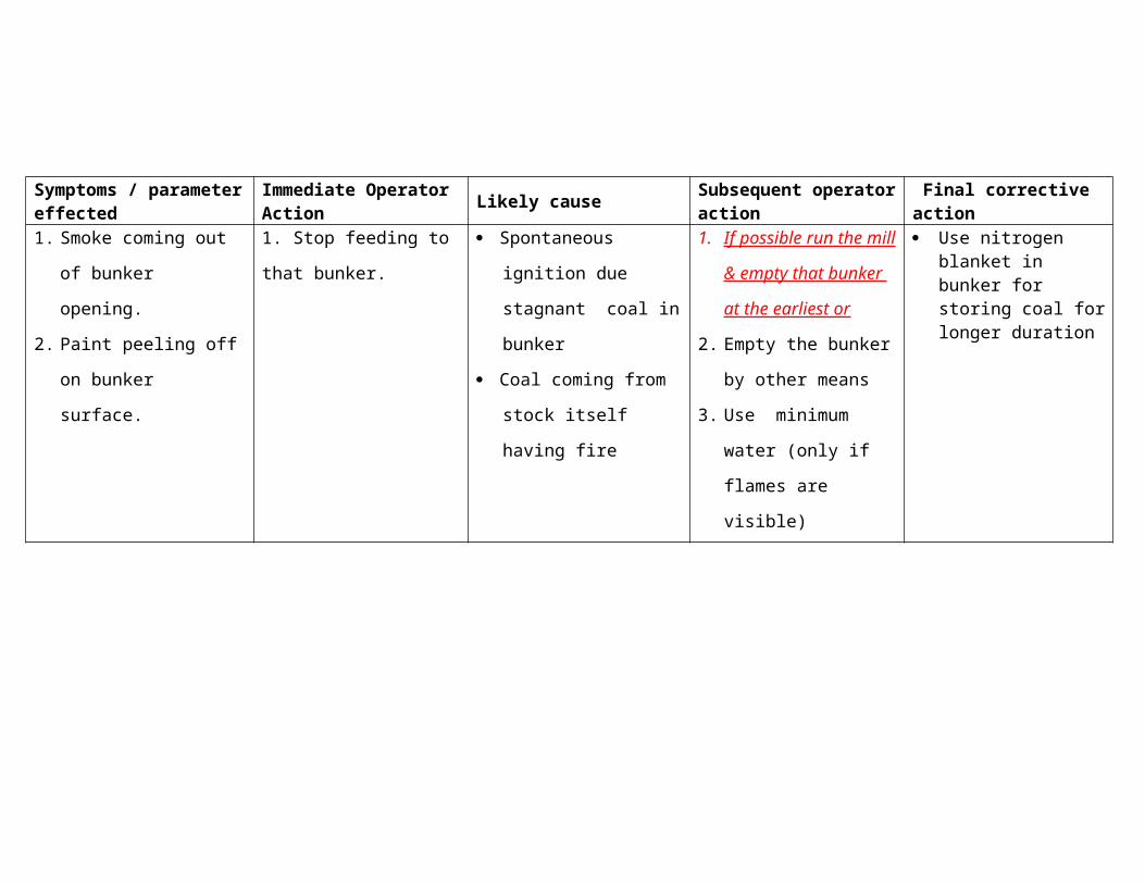
14. Fire in coal bunker
Symptoms / parameter effected
Immediate Operator Action
Likely causeSubsequent operator action
Final corrective action
1. Smoke coming out of
bunker opening.
2. Paint peeling off on
1. Stop feeding to that
bunker.
Spontaneous ignition
due stagnant coal in
bunker
1. If possible run the mill
& empty that bunker
at the earliest or
Use nitrogen blanket in bunker for storing coal for longer duration
bunker surface. Coal coming from stock
itself having fire
2. Empty the bunker by
other means
3. Use minimum water
(only if flames are
visible)
15. Fire in ESP
Symptoms / parameter effected
Immediate Operator Action
Likely causeSubsequent operator action
Final corrective action
1. Flue gas temp at ESP
outlet is much higher
than ESP inlet temp.
2. Outside fire noticed by
personnel
3. ESP insulation showing
signs of internal fire
1. Reduce unit load to
65MW if fire is inside
ESP
2. Trip ESP field
3. Isolate the power
supply of particular
pass/field.
4. Close particular ESP
inlet & outlet gate
Oil/soot deposit on
ESP fields
Very high unburnt in fly
ash & hopper heating
element Not switching
off
ESP transformer fire
1. If fire is outside ESP,
use extinguisher &
douse the fire.
2. Inform fire man
3. Open ESP man holes
4. Open ESP ash
hopper drain
plugs/man hole
5. Quench the fire with
fire hydrant water
16. Fire in fuel oil storage
Symptoms / parameter effected
Immediate Operator Action
Likely causeSubsequent operator action
Final corrective action
1. Fire noticed by
personnel.
2. Fire alarm. if actuated
in local by any persons
after observing fire
3. Burning smell
1. Stop HFO /LFO
pumps
2. Isolate electrical
supply for all related
equipments.
Electrical short circuit
Very high Oil
temperature.
External fire conveyed
to oil tank
Improper earthling
causing spark due to
static current
1. Inform fireman
2. Put hydrant system
with foam into service
& quench fire
3. If it is local fire douse
with extinguisher.
Emergency Procedure
17. Fuel oil leakage
Symptoms / parameter Immediate Operator Action Likely cause Subsequent operator Final corrective
effected action action
1. Oil leak noticed by
personnel
2. Oil pressure low alarm
1. Stop corresponding oil
pump. If leak is in pump
discharge line.
Fuel oil pipe
puncture by any
means.
Any control valve,
isolation valve,
pump gland/flange
leak
Gun leak due to
washer damaged.
1. Isolate leaking point
2. Inform fireman
3. Arrange to clean
leaked oil
Attend leaking
point
18. Generator winding temp raising fast
Symptoms / parameter
effectedImmediate Operator Action Likely cause
Subsequent operator
action
Final corrective
action
1. Generator winding
temp. high alarm.
2. Generator hot gas
temp>600C.
1. Reduce generator MVAR
loading to zero.
2. Reduce generator load
gradually till winding temp.
Raising trend reverses.
High MVAR loading
Overloading of
generator
ACW flow to
hydrogen cooler
low
Hydrogen cooler air
locked
1. Check ACW pressure
at Hydrogen cooler. If
required start standby
ACW pump.
2. Vent hydrogen cooler.
3. Fill hydrogen if
pressure is low.
19. Flash over
Symptoms / parameter
effectedImmediate Operator Action Likely cause
Subsequent operator
action
Final corrective
action
1. Observed by personnel
2. Fire alarm
1. Trip the switch gear in
which flash over has
occurred
Loose contacts
Short-circuits
Over load
If flashover is observed in
an equipment, then isolate
that equipment electrically
Insulation failure
Switching/lightning
voltage surges
20. Heater level going high
Symptoms / parameter
effectedImmediate Operator Action Likely cause
Subsequent operator
action
Final corrective
action
1. Heater level high alarm 1. If heater is not bypassed in
auto, bypass it on feed
water/condensate side.
2. Take heater level controls
in to manual and open it
fully
Drip control valve
failure.
Failure of drip auto
control due to
wrong level sensing
Heater Tube
leakage/failure
1. Check level locally and
confirm level
transmitter is reading
correct.
2. Open feed water side
IBV /condensate side
valve partially to
confirm whether
heater tube is leaking
If tube leak is
confirmed
isolate heater
totally and
release for
maintenance.

21. High axial shift
Symptoms / parameter
effectedImmediate Operator Action Likely cause
Subsequent operator
action
Final corrective
action
1. Axial shift high alarm
2. Turbine will trip at axial
shift very high limit of
0.5mm
3. Overloading of thrust
pads & thrust bearing
1. Reduce load to reduce
axial shift
2. Check all stop valves /
governing valves are
uniformly open
Abrupt change in
load
Sudden drop of
steam temperature
Sudden closure of
1. Maintain steam
parameter steady
2. If turbine has tripped
check vacuum breaker
has opened
3. Check vibrations
/return oil temp raise extraction valves
Too fast pick up of
load
Turbine overload
Silica deposits on
turbine blades
Turbine internal
damaged
GSC fan not
functioning
during coasting down
4. Note coasting down
time
5. If salting is suspected
arrange for early steam
washing of turbine or
other methods of
cleaning
22. Hydrogen leak from generator
Symptoms / parameter
effectedImmediate Operator Action Likely cause
Subsequent operator
action
Final corrective
action
1. H2 pressure in
generator casing low
alarm
2. Seal oil system fault
alarm
3. If seal oil pressure is
low standby oil pump
will start.
4. Winding temperature
may increase
5. Hot Gas temperature
may increase
1. If hydrogen pressure
reaches <1 ksc trip
generator & purge
generator with CO2
Seal oil running
pump trips &
standby AC & DC
pump fails to start
Seal oil pressure to
seal is low
DPR malfunction
Hydrogen leakage
developed in
generator system
Seal oil leakage
from
piping/valve/flanges
2. Try to establish seal oil
pressure by starting
stand by pump or by
closing DPRV inlet MIV
if seal oil pressure is
low.
3. If leaking point is
identified, try to isolate
it. If not possible,
23. LRSB not retracting
Symptoms / parameter
effectedImmediate Operator Action Likely cause Subsequent operator action
Final
corrective
action
1. LRSB not retracted
alarm
2. Observed from local
1. Reset the module & give
retract command from
local push button. If it
fails to retract even after
module is reset, switch-
off the module.
Forward motor trip
after advancing
Lance jammed after
advancing
LRSB clutch de
coupled after
advancing
Electrical supply
failure during
operation
Chain broken.
1. Reduce soot blower
header pressure to 3-
4Ksc.
2. Disengage the clutch and
try to retract manually from
handle. If it is retracting do
not release handle in the
middle ( If handle is to be
released in the middle, first
engage the clutch & then
only release) .
3. Inform maintenance if it is
not retracting manually
also.
4. Try retracting with
additional assistance for
If LRSB could
not retracted,
ask
maintenance to
insert dummy
in steam supply
line flange so
that other
blower
operation can
be carried out.
max. one hour.
5. If it could not be retracted
within one hour, reduce
pressure to zero ksc & try
again.
24. Lube oil leak/MOT level going low
Symptoms / parameter
effectedImmediate Operator Action Likely cause
Subsequent operator
action
Final corrective
action
1. MOT level low alarm
2. Oil pressure low alarm
if oil leak is from oil
supply line to bearing.
3. Oil leak observed from
local
1. If leak is more and could
not be isolated, reduce
load & trip the unit.
2. If leak is less and
confinable. Top up MOT
and inform firemen.
MOT drain is
opened
Lube oil cooler tube
leakage
Lube oil line/ flange
/filter leakage
Leakage from TG
1. Check any drain in
MOT area is open, if
open close it
2. If leakage is before
lube oil pump NRV
change over the pump
(change over will
Stop turbine
lube oil pump
after turbine
comes to
barring gear
and arrange
for attending
4. Oil collected in drain oil
tank/CEP pit
bearings
Seal oil system oil
leakage/seal oil
cooler tube leakage
Charging of
standby oil cooler
Oil entering
generator casing
from seals
Oil draining out
through centrifuge.
happen in auto on lube
oil pressure low)
3. Check centrifuge for
seal break and oil
draining out
4. Check oil channel
5. Check lube oil cooler
water side drain/vent
for presence of oil
6. Check seal oil cooler
water side drain/vent
for presence of oil
7. If any cooler leak is
noticed change over
that cooler.
leak.
Clean oil
leaked out to
avoid fire
hazard
25. Oil spill noticed in bottom ash hopper
Symptoms / parameter
effectedImmediate Operator Action Likely cause
Subsequent operator
action
Final corrective
action
1. Oil traces noticed in
bottom ash hopper from
local
2. Oil burner flame not
visible from peep hole
1. If any burner is in service
without flame, trip that
corner immediately
Burner in service
without flame
Oil nozzle valve
passing
Atomising steam/air
pressure very low
Oil specification
different from
designed one.
1. Check for the passing
oil gun & isolate it
2. Check for atomising
steam / air pressure
and adjust it
26. One of the turbine control valve fail to close
Symptoms / parameter
effectedImmediate Operator Action Likely cause
Subsequent operator
action
Final corrective
action
1. While reducing load, it
will not reduce below
certain MW even if load
set point is less
2. Stuck Valve position
feed back will show
open position control
room whereas other
valve will go for close.
3. High speed control will
act
1. Reduce turbine load to
100MW(if unit is in
service). If turbine has
tripped. close MS1.2.3 &4
& depressurise MS & RH
line
2. Open corresponding MAL
drain before & after control
valve(Partially)
Valve mechanically
stuck
Trip mechanism not
working
Oil not getting
drained from
actuator
1. If valve has stuck.
Reduce boiler pressure
& shut down unit.
27. One phase of the GT poles fail to open after unit trip
Symptoms / parameter
effectedImmediate Operator Action Likely cause
Subsequent operator
action
Final corrective
action
1. Pole Discrepancy alarm
will come
2. LBB protection will trip
all the breaker
connected to that bus
3. TG speed does not
drop after trip
4. TG draws current from
grid (reverse power)
5. Negative sequence
1. Trip all the 220 kV breaker
connected to the particular
bus including bus coupler.
(If LBB not acted)
2. Trip field breaker manually.
if it did not opened.
3. Open isolators of GT
breaker
Breaker contact
mechanically stuck
1. Normalise supply by
charging Line .ST and
Bus coupler.
Attend GT
breaker before
restarting
Turbine
current in Generator
6. LP exhaust temperature
going high
28. scanner fan tripped & DC fan fail to start
Symptoms / parameter
effectedImmediate Operator Action Likely cause
Subsequent operator
action
Final corrective
action
Scanner air to furnace DP low alarm
Scanner air fans tripped alarm
1. Trip the boiler Dc fan fails to start after AC fan trips
Both fan getting
over load/electrical
fault
1. Try to start fan by resetting overload relay
2. Increase FD fan discharge pressure so that some air will always available for scanner
3. If not happening reduce load to
Lightup boiler
only after
starting
scanner air
fam
minimum & get the fan started at the earliest.
4. If Scanner air fan could not be restarted even after reasonable time delay trip the boiler
29. seal oil pressure going low
Symptoms / parameter
effectedImmediate Operator Action Likely cause
Subsequent operator
action
Final corrective
action
1 Drum level dropping fasta Likely causes
One of the running BFP might have trippedSudden tripping of one or more Mills.Feeder might have tripped.FW control valve might have closed/stucked.Malfunction of auto control/scoop regulation.BFP recirculation might have opened of the running pump.Sudden reduction of load because of malfunction of EHTC.Sudden tube failure in water walls.HPBP might have opened.Inadvertent opening of EBD & low point drains.Drum pressure may be high.Drum level transmitters may be faulty.
b Plant responseDrum level LOW alarm appears.BFP's scoop rises to meet the demand if it is in auto.Boiler will trip on drum level very low.

In extreme case, if water level falls below visible range of gauge glass, may affect the flow through downcomers & may lead to tube failure.
c Parameters of concern.Main steam /reheater temperatures ,drum level,dearator level
d Immediate expected or desirable operator action.See that standby BFP starts on tripping of running BFP or manually start when level drops to -100 mmwc & load the pump to the running pumps scoop.Check for any malfunction of auto control like scoop not raising or recirculation open in auto, take control into manual & make up drum level.Close CBD if it is open.Close HPBP if it is open.Remove corex burners (when level is above (-100 mmwc)).Caution: Do not do any major removal of fuel at drum level (-100 mm & above., like mill tripping, burner removal)
e Final correction activity.Check drum level is getting stabilised.Ensure drum level controls are in auto.Check feedwater flows matches with steam flow for full load, if deviation is more then check for any leak in boiler area.Ensure for the availability of standby BFP as early as possible.Check for local level gauge & transmitters.Check boiler low point drains & EBD.Check for scoop controls for any linkage failures.
2 Drum level shooting up fasta Likely causes
Malfunction of feed controls.Sudden increase of load (due to malfunction of EHTC)Drum level transmitters may be faulty.Sudden increase of firing rate.Scoop /control valves might have stucked.Sudden opening of HPBP.
b Plant response
Drum level high alarm will appears.On drum level high high, boiler will trip.
c Parameters of concern.SH/RH temperatures drum level.
d Immediate expected or desirable operator action.Check the hydrostep level, if it is high take drum level control to manual & match feedwater flow with steam flow.Open emergency drain/CBD drain.Open MS strainer drains.Try to reduce the load so as to control the water level (if water level is due to upward load surge).
e Final correction activity.Check drum level is getting stabilised.Ensure drum level controls are in auto.Check feedwater flow matches with steam flow.Check for stuck of feed control valves & scoop.Check the level at local, hydrostep and transmitters are matching.
3 Rapid Boiler steam pressure risea Likely causes
Corex calorific value might have changed drastically.Sudden loading of mill.High firing rate.Feeder hunting.Malfunction of CMC.Sudden dropping of generator load.
b Plant responseHPBP will open if it is in auto.Reheater safety valve will popup first & then on high steam pressure, reaching in stages may blow EMRV & superheater SV & drum safety valves.Throttle pressure high alarm will appearsAPH FG I/L O2 low alarm will appearsDrum level will vary.

Generator will get more loaded because of pressure correction of EHTC.c Parameters of concern.
MS /RH temperature, Drum level, APH inlet O2, HP/LP bypass,d Immediate expected or desirable operator action.
Take the unit into manual mode if it is in CMC & reduce the fuel firing.For momentary action additional load can be taken Trip the malbehaving feeder/mill & reduce PA airflow through that mill.Check for pressure drop & if it is not holding remove the corex burners.Caution:Donot reduce the fuel when the drum level is around -100mmStart standby BFP when drum level reaches -100mm & rise the scoop to running BFP scoop.
e Final correction activity.Check for reseating of safety valveAs soon as the pressure starts dropping, restore the correct fuel input.Stop the third running BFP and keep it in standby.Ensure drum level got stabilised. Check for closure of HP bypass.Ensure pressure is stable.Bring back the unit load to normal.
4 EMRV floating and reseating in successiona Likely causes
Maloperation of valve.High fuel firing rate.MS pressure fluctuation.Maloperation of turbine control valve.
b Plant responseDrum level will vary.Generator load will vary.Hp bypass will open if it is in auto & may hunt.Ms temp and RH temp variation.
c Parameters of concern.Drum level, Ms temp and RH temp, MS pressure.
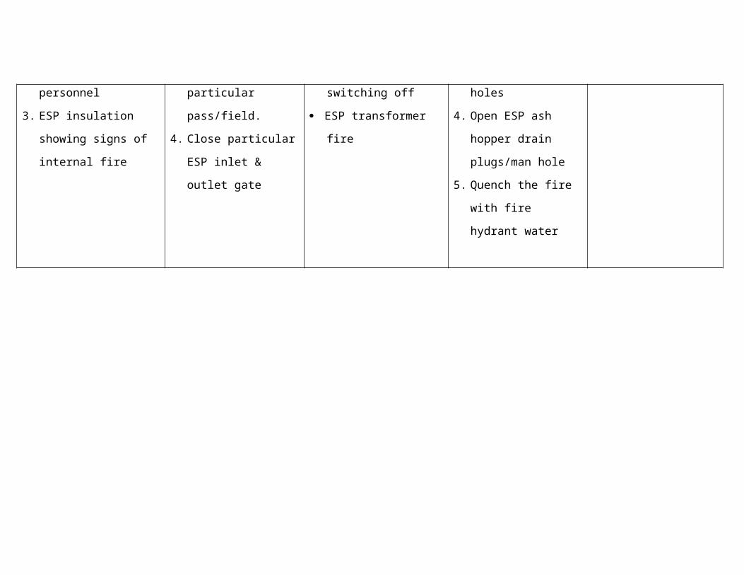
d Immediate expected or desirable operator action.Reduce the fuel firing if pressure is really high. If MS pressure is less, still EMRV is operating, keep selection switch to "OFF" so that the EMRV will not operate.Even by putting "off ", valve is still in open condition, its manual isolation valve can be closed.
e Final correction activity.Ensure for proper re-seating of the valve & put back in auto.
5 RH SV floating and reseating in successiona Likely causes
HP bypass might have opened in auto & LP bypass has not opened.Maloperation of valve.Opening /hunting of HP bypass.
b Plant responseHRH steam pressure high alarm will appear.MS and RH temp variationGenerator load will rise.Drum level will vary.
c Parameters of concern.Drum level, MS and RH temperature
d Immediate expected or desirable operator action.If LP bypass not opened, trip reset & open the valve by around 10% & put back in auto.Reduce the MS pressure, if it is actually high, so that HP bypass will close in auto.Reduce the load until the valve re-seat
e Final correction activity.Check for proper seating of the valve.Inform to maintenance isf & it is not re-seating at lower pressure also.
6 Corex CV decreasea Likely causes
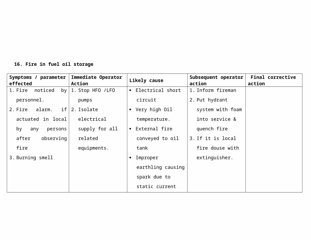
Malfunction of COREX process. Variation in corex constituents %.
b Plant responseMs pressure will drop fastGenerator Load will drop.O2 at APH FG inlet will rise & high alarm may appears.
c Parameters of concern.MS pressure, load, APH flue gas inlet oxygen.
d Immediate expected or desirable operator action.Reduce load set point inorder to hold the boiler pressureEnquire EMD Dept about CV variation & if corex is stable then raise the feeding on running mills.
e Final correction activity.Ensure O2 at APH i/t is normalRestore the fuel input to boiler once the CV of corex stabilises.
7 Rapid Boiler steam pressure decreasea Likely causes
Sudden drop in Calorific value or pressure of corex.Tripping of mill or feeder.Sudden rise in load.Disturbed combustion conditions in furnace.Mill might have got unloaded.
b Plant responseMS pressure will drop.Generator load will come down.Drum level will drop.O2 at APH FG inlet will rise.
c Parameters of concern.Drum level, generator load, MS/RH temperatures, APH FG inlet O2.
d Immediate expected or desirable operator action.Check for any mill unloading.
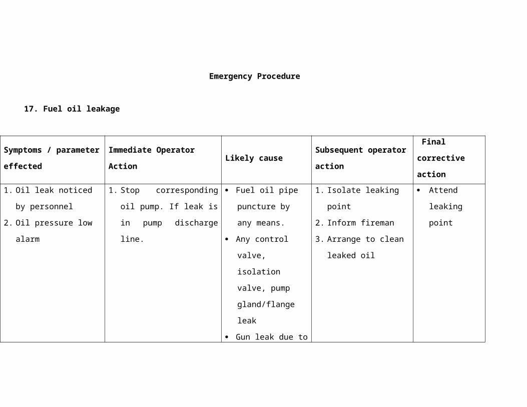
Reduce load set point to hold the MS pressure around 110 kg/cm2.Check boiler flame, take oil elevation into service.(don't take oil when combustion conditions are very poor)Monitor drum levels during this disturbance, if it is dropping very fast, start standby BFP & load the scoop equal to running pump scoops.
e Final correction activity.Ensure drum level is stable.If mill is unloaded stop the mill & take other mill into service.Increase load set point to full load based on the fuel.Remove oil if it is introduced if furnace conditions are good or bright.
8 MS temperature rising fasta Likely causes
Inadequate spray due to malfunctions of spray control valves.Excess airflow.Instrument air pressure may not be adequate.Burner tilt Maloperation.Leakage in the spray line.Low feed water temperature.Ms pressure may be high.Heavy furnace slagging
b Plant responseMS/RH temperature high alarm will appear.Spray control valves will go for further opening.Load will rise for the same pressure.If temperature is very high ,turbine will trip."Positive" turbine expansion
c Parameters of concern.MS/RH temperatures, feedwater flow, drum level, HP exhaust temperature.
d Immediate expected or desirable operator action.Tilt burner down.Control the spray flow in manual so that stage -1 o/l temp will be around 450 deg.C &
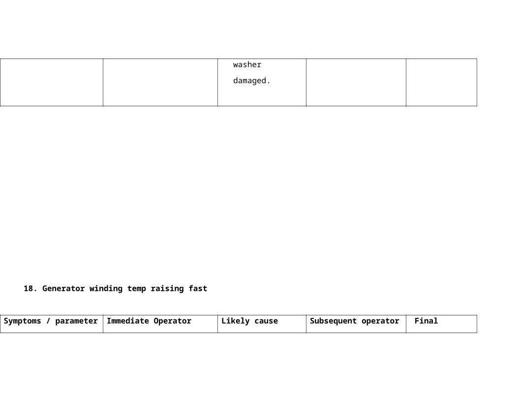
stage -2 o/l temp around 505 deg.C, if temp control response is poor in autoIf rate of pressure rise is more, then pick up load if margin is there.Reduce firing rate (preferably top elevation).Reduce airflow based on the O2 percentage.
e Final correction activity.Introduce soot blowing if MS/RH temperatures are still maintaining high & spray quantity is more..Restore back the temp controls in auto if it has been taken in manualCheck for any malfunction of spray control valves & isolate such type of valve.Burner tilt can be kept horizontal.
9 RH temperature rising fasta Likely causes
Inadequate spray due to malfunctions of spray control valves.Cutting in of Top mill into service.Instrument air pressure may not be adequate.Cutting in corex in quick succession.Excess airflow.MS temperature may be high.MS pressure may be high.Leakage in the spray line.Heavy furnace slagging.Burner tilt Maloperation.
b Plant responseRH temperature high alarm will appear.RH metal temperatures high alarm will appear.Amount of spray will rise.Load will rise for the same pressure."Positive" turbine expansion.
c Parameters of concern.RH temp, drum level, feed water flow, feedwater differential pressure.
d Immediate expected or desirable operator action.
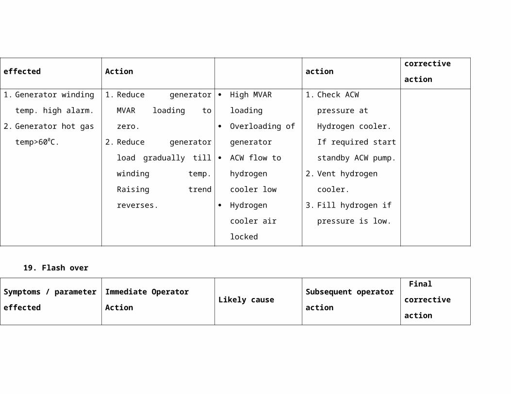
Control the spray flow manually at RH inlet around 250 deg.C, if temp control response is poor in auto.Tilt burner down. Check for MIV's open before & after spray control valvesReduce air flow if its more.If rate of pressure rise is more, then pick up load if margin is there.Reduce firing rate.
e Final correction activity.Introduce soot blowing if temperature is maintaining high & spray is high.Keep the burner tilt in horizontal condition.Restore back the control in auto if it has been taken in manual.
10 MS temperature falling fasta Likely causes
Tripping of top elevation millMalfunctioning of spray control valves.Less air flowInstrument air pressure may not be adequate.Low burner tiltMore sprayHigh feed water temperature
b Plant responseMS temperature low alarm will appear.Unit may trip on MS temp very low.Turbine expansion may become Negative.
c Parameters of concern.Ms temp, drum level, feed water flow.
d Immediate expected or desirable operator action.Close the spray control valves by taking into manual.Tilt burner upward.Check airflow &Rise if necessary.Top elevation mill can be taken into service /firing can be raised
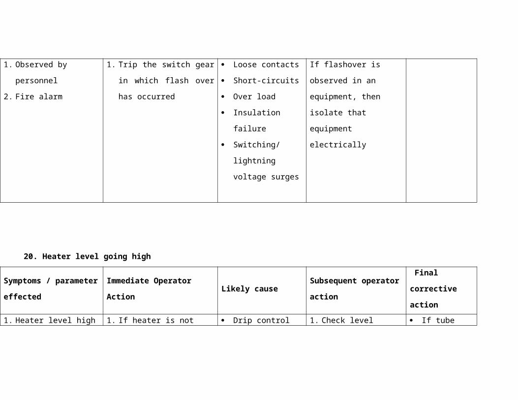
Check for MIV open before & after control valves.e Final correction activity.
Initiate LRSB soot blowing if temperatures are maintaining still less.Observe for improvement in temperature.Restore back the controls in auto (spray control)Check for any malfunction of control valve & isolate it.
11 RH temperature falling fasta Likely causes
Less air flowTripping of top elevation millInstrument air pressure may not be adequate.Low burner tilt.More spray.Malfunctioning of spray control valves.
b Plant responseRH temperature low alarm will appear.Negative expansion of turbineUnit may trip on RH temp very low.
c Parameters of concern.MS/RH temp, drum level, feed water flow.
d Immediate expected or desirable operator action.Close the spray control valves by taking in manual.Tilt burner upward.Rise the Airflow.Top elevation mill can be taken into service /firing can be raised.
e Final correction activity.Initiate LRSB soot blowing if temperatures are maintaining still less.Observe for improvement in temperature.Restore back the controls in auto (spray control)Check for any malfunction of control valve & isolate it.
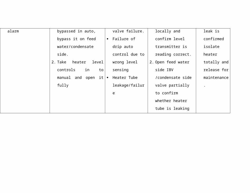
12 One of the Turbine control valve fails to closea Likely causes
Trip SOV may be problem.Trip coil faultyChoking in servo valve portsProblem in control valve linkage.Airlock in control oil systemMechanical problem
b Plant responseLoad huntingLoad cannot be varied as per requirementEHTC controller O/P will reduce very much to maintain same load .Speed fluctuation will occur during synchronising time.
c Parameters of concern.Speeds, Load, pressure, control oil pressure, and drum level, HP exhaust temperature.
d Immediate expected or desirable operator action.Inform immediately to Maintenance dept.Trip the unit ,if there is no any ready solutionCheck control oil pressure.
e Final correction activity.Ensure proper functioning of control valves
13 Control oil circulation pump faileda Likely causes
Pump may be tripped on any electrical protectionsb Plant response
Control oil tank temperature will rise.Control oil pressure may drop because of viscosity reduction.HSU Tank temperature high alarm will appear.
c Parameters of concern.Control oil temperature, HSU header pressure,
d Immediate expected or desirable operator action.
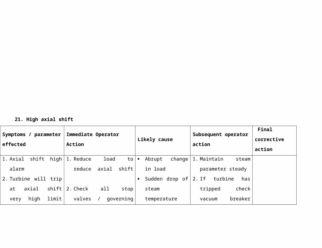
Check pump module along with electrical maintenance.Try to restart the pump as early as possible.
e Final correction activity.Ensure continuous running of the pump.
14 Control oil leakagea Likely causes
Damage in pipe line/pin hole puncture.N2 accumulator diaphragm might have punctured.Control oil pressure may be very high.
b Plant responseStandby pump will pick up on header pressure lowBecause of low pressure ,control valves may go for closeMS pressure may rise.LP bypass malfunction.Unit may trip.
c Parameters of concern.Unit load ,pressure, HSU pressure.
d Immediate expected or desirable operator action.If leakage is heavy, turbine to be tripped on fire protection channel.
If leakage is heavy personal safety to be ensured and fire fighting dept to be informed.
Locate point of leakage.e Final correction activity.
Stop S/B pumpEnsure leakage has been arrested fullyEnsure all the parameters are restored backEnsure control oil pressure is normal.
15 One of the Turbine control valve closesa Likely causes
Trip drain SOV may be problem.Trip coil faulty
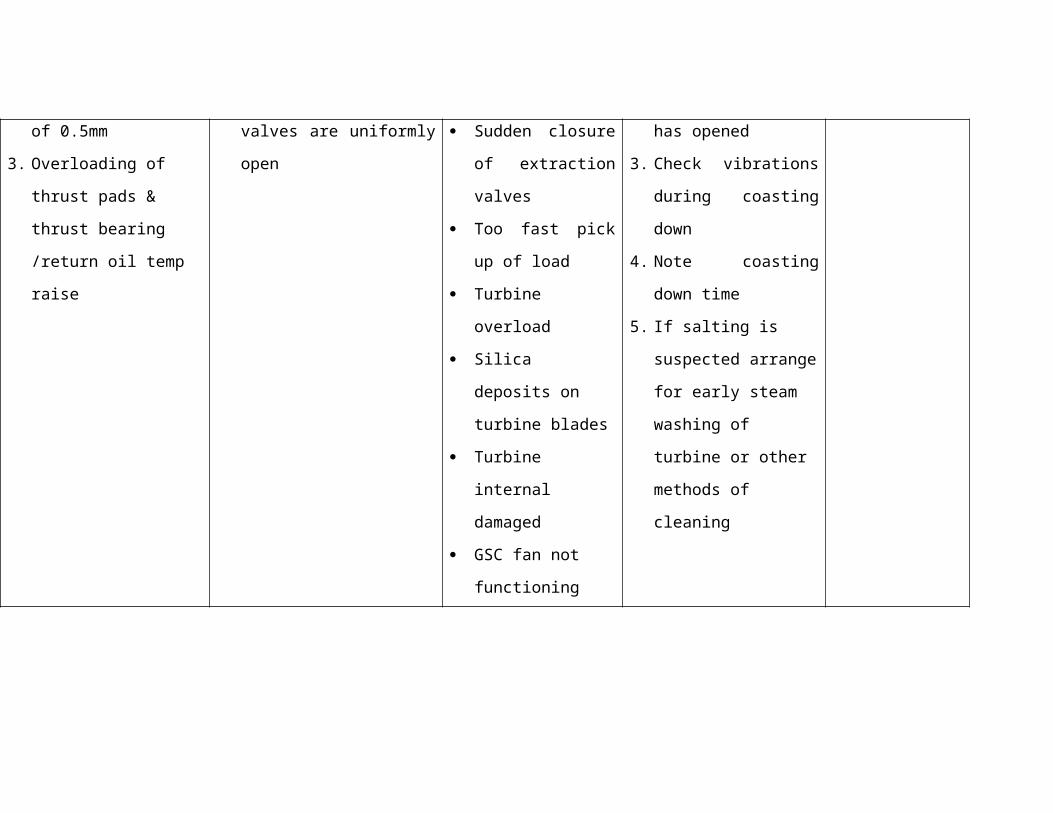
Problem in control valve linkage.Mechanical problem.Airlock in control oil systemChoking in servo valve ports.
b Plant responseFirst stage pressure will rise than the normal value, if at all problem is there with IP control valve.HP exhaust temperature will rise.RH pressure will rise than the normal.RH Safety valves may pop.Thrust loading/axial shift may varyLoad huntingLoad cannot be varied as per requirementSpeed fluctuation will occur during synchronising time
c Parameters of concern.Load, pressure, control oil pressure, drum level, HP exhaust temperature, axial shift.
d Immediate expected or desirable operator action.Maintenance dept., to be informed immediatelyCheck for control oil pressureKeep standby pump running in manual mode.If possible reduces load and pressure.Control boiler firing.Control SH & RH temperature.
e Final correction activity.Ensure proper functioning of control valves.Restore back all the parameters.