public building commission of chicago chicago...public building commission of chicago mayor richard...
TRANSCRIPT

PUBLIC BUILDING COMMISSION OF CHICAGO
Mayor Richard M. Daley, Chairman Erin Lavin Cabonargi, Executive Director ADDENDUM NO. 1 1 DATE: 10/20/2009
ADDENDUM NO. 1 TO CONTRACT NO. 1497 FOR
40th Street Beach Comfort Station And
Osterman Beach Comfort Station For
New Construction
DATE: October 20, 2009 NOTICE OF CHANGES IN CONTRACT DOCUMENTS The following changes are hereby made in the Contract Documents. CHANGES TO BOOK 1‐ Project Information, Instructions To Bidders, And Execution Documents Change 1: Section IIB ‐ delete “(180) Days after the Notice to Proceed.” Add “May 21, 2010.” CHANGES TO BOOK 3 ‐ TECHNICAL SPECIFICATIONS: Change 2: Cover sheet:
A. Omit contract number 1498 for Osterman. Both 40th Street and Osterman are under contract number 1497.
Change 3: Table of contents: A. Revise page count for Section 13461 – Rainwater Harvesting System from 3 to 4.
Change 4: 01524‐5 3.6 A. delete "landfill or incinerator acceptable to authorities having jurisdiction" and add "Contractor shall comply with all applicable regulatory requirements and other federal, state or local laws, codes and ordinances that govern or regulate the handling, transportation and disposal of waste from this site. The Contractor shall mark, label, placard, package and manifest waste as necessary in accordance with all applicable state, federal and local regulations. “
Change 5: 02220‐2 1.6 Hazardous Materials A. delete "U.S. EPA" add "defined as a waste pursuant to 40 CFR Part 261; Illinois Administrative Code Title 35, Section 721.103 (35 IAC 721.103) or Section 3001 of the Resource Conservation and Recovery Act of 1976, P.L. 94‐580 during the demolition process…
Change 6: 02220 1.6 B. Delete ‐ “Owner will employ a Contractor experienced and certified…” and replace with Contractor shall retain a Contractor experienced and certified …to perform removal and disposal work.” ADD ‐ “This work shall be considered incidental to the scope of work in these bid documents.”
Change 7: 02240 ADD “1.3 B. Follow Metropolitan Water Reclamation District permitting process as required for discharging into city of Chicago sewer systems. Provide all testing results and required forms to the Owner once approval is granted.”

PUBLIC BUILDING COMMISSION OF CHICAGO
Mayor Richard M. Daley, Chairman Erin Lavin Cabonargi, Executive Director ADDENDUM NO. 1 2 DATE: 10/20/2009
Change 8: 02300: 1.5 D.2. ‐ Delete “1,000 tons of material” and add “2,500 tons of material” 3.17B. ‐ Add after “property” >>>”to an open and active permitted Subtitle D landfill. 3.17 –Delete C and D this is not a remediation site.
Change 9: 02900: 1 add to 1.1 Related Documents a B. 02300 Earthwork Add to 1.3 “E. All top soil shall not exceed Title 35: Environmental Protection Subtitle G: Waste Disposal Chapter I: Pollution Control Board Subchapter F: Risk Based Cleanup Objectives, Part 742, Tiered Approach To Corrective Action Objectives, Appendix B, Table A values for 35 ILL. ADM CODE 740 APPENDIX A Target Compound List (TCL) parameters. A copy of these results shall be provided to the Owner within 45 days of topsoil import to the site. Specific testing requirements are covered in section 02300. Material shall be approved by owner prior to delivery to site.”
Change 10: 13461 – Rainwater Harvesting System Revise section 13461 as follows: Add the following to Article 2.2 SYSTEM DESCRIPTION after the last paragraph in the Article: Water Harvesting System with 3 Digital Displays for the Atlantis underground storage tank, the day tank, and municipal water supply shall be programmable and mounted in a NEMA 4X Fiberglass enclosure in the location as indicated on the drawings.
Add subparagraph 7 to 2.3,A as follows: 7. Signet Model 2537 Paddlewheel Flow Sensor (for municipal water supply) 8. Water Harvesting System Digital Display a. Display: Precision Digital Model PD683 with back lit display or approved equal. 1) Quantity: 3 digital displays 2) Displays shall be loop powered. b. Enclosure: Vinckier Model VJ1210HW or approved equal. 1) NEMA 4X Fiberglass 12" x 10" with stainless steel hinge and latch.
Change 11: 15410 ‐ Plumbing Fixtures A. Changed drinking fountain manufacturer to Haws Corp.
Change 12: 16118 ‐ DUCTBANKS A. Paragraph 3.1,E ‐ remove reference to “Commonwealth Edison Company”
and replace with “Chicago Park District”. Change 13: 16421 ‐ UTILITY SERVICE ENTRANCE
A. Delete specification section in its entirety. Change 14: 16124 ‐ MEDIUM‐VOLTAGE CABLES
A. Insert specification section. See attached. Change 15: 16271 ‐ MEDIUM‐VOLTAGE TRANFORMERS
A. Insert specification section. See attached. Change 16: 16341 ‐ MEDIUM‐VOLTAGE SWITCH
A. Insert specification section. See attached. CHANGES TO DRAWINGS: Change 17: Sheet G0.0, Cover Sheet
A. (Osterman Only) Change PBC Contract number from 1498 to 1497. Both 40th Street and Osterman Comfort Stations are bid under one contract (number

PUBLIC BUILDING COMMISSION OF CHICAGO
Mayor Richard M. Daley, Chairman Erin Lavin Cabonargi, Executive Director ADDENDUM NO. 1 3 DATE: 10/20/2009
1497) Change 18: Sheet C2.1, Site Plan (40th Street and Osterman Beach Houses)
A. Added Permeable Pavement along Lake Side of the Building.(40th Street Only) B. Added outdoor drinking fountain. C. Added Infiltration Tank to Atlantis Underground system. D. Added new catch basin.
Change 19: Sheet C3.1,Grading Plan (40th Street and Osterman Beach Houses) A. Added Elevation shot to new catch basin in conjunction with Atlantis System. B. Added berming to site. (Osterman Only) C. Adjust rim elevation of existing manhole near westerly berm (Osterman Only)
Change 20: Sheet C0.3, Erosion Control Plan (Osterman Beach House Only) A. Moved Construction fence and silt fence per addition of berms B. Added note for erosion control blanket.
Change 21: Sheet C0.4, Erosion Control Notes (Osterman Beach House Only) A. Added detail for erosion control blanket
Change 22: Sheet C1.1, Site Demolition Plan (Osterman Beach House Only) A. Remove existing bush affected by the addition of berms B. Remove existing electrical stub‐out that will not be used, that will be affected by the berms.
Change 23: Sheet C4.1, Utility Plan (40th Street and Osterman Beach Houses) A. Added new catch basin in conjunction with Atlantis System. See C4.1 B. Added water line and sanitary sewer to/from outdoor drinking fountain. See C4.1.
Change 24: Sheet C5.2, Details (40th Street and Osterman Beach Houses) A. Revised trench drain detail per additional sewer line inflow. See C5.2.
Change 25: Sheet C5.3, Details (40th Street Beach House Only) A. Added Permeable Pavement Detail. See C5.3.
Change 26: Landscape A. All landscaping work and tree protection to conform to CPD standard tree
protection details per attached sheet ST‐872‐L1. Change 27: Sheet L‐1, Landscape Plan (Osterman Beach only)
A. Engineer’s berming was added to plan. See L‐1 B. Planting layout has been modified to work with proposed berming. See L‐1 C. Approximate limit of sod line has been adjusted to meet proposed berms. See L‐1 D. Perennial plantings have been added to plan per CPD request. See L‐1 E. Plant List has been modified to include perennials and new plant counts. See L‐1
Change 28: Sheet A1.1, Architectural Site Plan A. (40th Street only) Drawing 1: Permeable pavement has been added in front of
the building. See ASK‐01 B. (Osterman only) Drawing 2: Railing spacing dimensions have been adjusted.
See ASK‐07. C. (40th Street and Osterman) Drawing 1: Add outdoor drinking fountain as
located and noted on ASK‐05 and ASK‐06. Omit the two building‐mounted drinking fountains and associated plumbing from the Colonnade.
Change 29: Sheet A1.2, Architectural Site Details (40th Street only) A. Add details of Reserved Parking signs. See ASK‐02
Change 30: Sheet A2.1, Floor Plan

PUBLIC BUILDING COMMISSION OF CHICAGO
Mayor Richard M. Daley, Chairman Erin Lavin Cabonargi, Executive Director ADDENDUM NO. 1 4 DATE: 10/20/2009
A. General notes, add note #5, “where interior masonry walls meet exterior masonry walls, provide a masonry control joint, typical.”
B. Drawing 1: Life Guard Office 107, wall adjacent to Family Rest Room 106, add wall mounted digital display box for water harvesting system, mounted 5’‐0” AFF. See ASK‐04 for location.
Change 31: Sheet A4.1, Building Sections (Osterman only) A. Drawing 2: Dimensional width of Atlantis underground storage to be 6’‐8”, not 9’‐0”.
See ASK‐03 Change 32: Sheet P1.01, Plumbing Suspended Floor Plan
A. Relocated domestic water heaters. Deleted drinking fountains. Revised vent thru roof size. See PSK‐01.
B. Relocated domestic water heaters. Deleted drinking fountains. Revised vent thru roof size. See PSK‐02.
C. Revised vent thru roof size. See PSK‐03. Change 33: Sheet P1.00, Plumbing Underground Floor Plan
A. Coordinated water services to outdoor shower and drinking fountain. Deleted drinking fountain at building. See PSK‐04.
Change 34: Sheet P0.01, Plumbing General Notes, Abbreviations, and Symbols A. Changed drinking fountain to Haws Model 3500D. See PSK‐05.
Change 35: Sheet ES.00, Electrical Site Plan A. Revised site plan to clarify utilities scope of work (e.g. AT&T conduits,
Medium‐Voltage scope of work). See ES.00. B. Inserted new details (40th Street Beach Only) See ES.00.
a. Enlarged Electrical Site Plan b. Switchgear Ground Grid Detail
C. Revised site plan to clarify contractor‐provided AT&T conduits. See ES.00. Change 36: Sheet ES.01, Electrical Enlarged Site Plan
A. Clarified Utilities scope of work. See ES.01 B. Revised Keyed Notes. See ES.01
a. Keyed Note 5 for contractor‐provided AT&T conduits. (40th Street Beach only)
b. Keyed Note 7, formerly referencing CCTV poles, to say “NOT USED”. C. Removed all references to future CCTV pole including wiring, conduits, and
pole itself from electrical drawings. See ES.01 D. Revised details. See ES.01
Change 37: Sheet E1.01, Electrical First‐Floor Plan A. Revised Sheet Notes and Keyed Notes. See E1.01. B. Inserted power‐packs accessory for Occupancy Sensors. See E1.01. C. Inserted J‐box for digital display panel for the Atlantis Water Harvesting
system. See E1.01. D. Relocated power and disconnect switch for WH‐1 and WH‐3. See E1.01. E. Replaced Distribution Panel DP‐1 with Metering Cabinet. See E1.01.
Change 38: Sheet E2.01, Electrical Single‐Line Diagram A. Revised and updated single‐line diagram to reflect Medium‐Voltage power
distribution. See E2.01. B. Revised Sheet Notes. See E2.01.
Change 39: Sheet E3.01, Electrical Schedules A. Revised Panel board Schedule “CP‐1” and “HP‐1”. See E3.01.

PUBLIC BUILDING COMMISSION OF CHICAGO
Mayor Richard M. Daley, Chairman Erin Lavin Cabonargi, Executive Director ADDENDUM NO. 1 5 DATE: 10/20/2009
B. Revised Occupancy Sensor Specifications. See E3.01. C. Inserted Occupancy Sensor Wiring Diagram. See E3.01.
ATTACHMENTS: Drawings C0.3, 1 page (22”x34” format) C0.4, 1 page (22”x34” format) C1.1, 1 page (22”x34” format) C2.1 ‐ OSTERMAN, 1 page (22”x34” format) C2.1 – 40TH STEET, 1 page (22”x34” format) C3.1 ‐ OSTERMAN, 1 page (22”x34” format) C3.1 – 40TH STREET, 1 page (22”x34” format) C4.1 ‐ OSTERMAN, 1 page (22”x34” format) C4.1 – 40TH STREET, 1 page (22”x34” format) C4.3 – 40TH STREET, 1 page (22”x34” format) C5.2 – 40TH STREET, 1 page (22”x34” format) C5.2 ‐ OSTERMAN, 1 page (22”x34” format) C5.3 – 40TH STREET, 1 page (22”x34” format) L‐1 ‐ OSTERMAN, 1 page (22”x34” format) ST‐872‐L1, 1 page (22”x34” format) ASK‐01, 1 page (8.5”x11” format) ASK‐02, 1 page (8.5”x11” format) ASK‐03, 1 page (8.5”x11” format) ASK‐04, 1 page (8.5”x11” format) ASK‐05, 1 page (8.5”x11” format) ASK‐06, 1 page (8.5”x11” format) ASK‐07, 1 page (8.5”x11” format) PSK‐01, 1 page (8.5”x11” format) PSK‐02, 1 page (8.5”x11” format) PSK‐03, 1 page (8.5”x11” format) PSK‐04, 1 page (8.5”x11” format) PSK‐05, 1 page (8.5”x11” format) ES.00 (Osterman Beach), 1 page (22”x34” format) ES.01 (Osterman Beach), 1 page (22”x34” format) E1.01 (Osterman Beach), 1 page (22”x34” format) E2.01 (Osterman Beach), 1 page (22”x34” format) E3.01 (Osterman Beach), 1 page (22”x34” format) ES.00 (40th Street Beach), 1 page (22”x34” format) ES.01 (40th Street Beach), 1 page (22”x34” format) E1.01 (40th Street Beach), 1 page (22”x34” format) E2.01 (40th Street Beach), 1 page (22”x34” format) E3.01 (40th Street Beach), 1 page (22”x34” format) Specifications Section 15410 Section 16124 Section 16271 Section 16341
END OF ADDENDUM NO.1


SECTION 15410 - PLUMBING FIXTURES
PART 1 - GENERAL
1.1 WORK INCLUDED
A. Plumbing Fixtures & Trim.
1.2 RELATED DOCUMENTS
A. Section 15140 – Domestic Water Piping.
B. Section 15145 – Domestic Water Piping Specialties.
C. Section 15150 – Sanitary Waste and Vent Piping.
D. Section 15155 – Sanitary Waste Piping Specialties.
1.3 QUALITY ASSURANCE
A. Codes and Standards:
1. No plumbing fixture, special equipment, device or piping shall be installed which will provide cross-connection or interconnection between drinking water and non-potable water supply.
2. Where possibility of back-siphonage exists, water supplied to fixtures shall be introduced through vacuum breakers.
3. Plumbing fixtures reference standards:
a. Vitreous fixtures: NBS-CS. b. Enameled cast iron: NBS-CS. c. Plumbing Fixtures (land use): FS-WW-P-54l-b(2).
1.4 SUBMITTALS
A. Refer to Section 01330 – Submittal Requirements.
1. Product Data.
a. Fixtures b. Faucets and valves. c. Fixture supports.
PART 2 - PRODUCTS
2.1 ACCEPTABLE MANUFACTURERS
A. The following is a list of manufacturers' names of material and equipment that are acceptable.
PLUMBING FIXTURES 15410 - 1
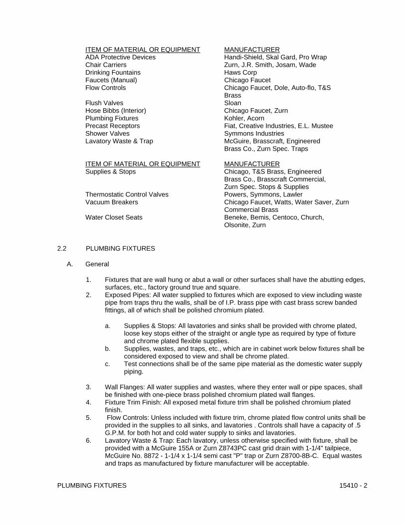
ITEM OF MATERIAL OR EQUIPMENT MANUFACTURER ADA Protective Devices Handi-Shield, Skal Gard, Pro Wrap Chair Carriers Zurn, J.R. Smith, Josam, Wade Drinking Fountains Haws Corp Faucets (Manual) Chicago Faucet Flow Controls Chicago Faucet, Dole, Auto-flo, T&S Brass Flush Valves Sloan Hose Bibbs (Interior) Chicago Faucet, Zurn Plumbing Fixtures Kohler, Acorn Precast Receptors Fiat, Creative Industries, E.L. Mustee Shower Valves Symmons Industries Lavatory Waste & Trap McGuire, Brasscraft, Engineered Brass Co., Zurn Spec. Traps
ITEM OF MATERIAL OR EQUIPMENT MANUFACTURER Supplies & Stops Chicago, T&S Brass, Engineered Brass Co., Brasscraft Commercial, Zurn Spec. Stops & Supplies Thermostatic Control Valves Powers, Symmons, Lawler Vacuum Breakers Chicago Faucet, Watts, Water Saver, Zurn Commercial Brass Water Closet Seats Beneke, Bemis, Centoco, Church,
Olsonite, Zurn
2.2 PLUMBING FIXTURES
A. General
1. Fixtures that are wall hung or abut a wall or other surfaces shall have the abutting edges, surfaces, etc., factory ground true and square.
2. Exposed Pipes: All water supplied to fixtures which are exposed to view including waste pipe from traps thru the walls, shall be of I.P. brass pipe with cast brass screw banded fittings, all of which shall be polished chromium plated.
a. Supplies & Stops: All lavatories and sinks shall be provided with chrome plated, loose key stops either of the straight or angle type as required by type of fixture and chrome plated flexible supplies.
b. Supplies, wastes, and traps, etc., which are in cabinet work below fixtures shall be considered exposed to view and shall be chrome plated.
c. Test connections shall be of the same pipe material as the domestic water supply piping.
3. Wall Flanges: All water supplies and wastes, where they enter wall or pipe spaces, shall be finished with one-piece brass polished chromium plated wall flanges.
4. Fixture Trim Finish: All exposed metal fixture trim shall be polished chromium plated finish.
5. Flow Controls: Unless included with fixture trim, chrome plated flow control units shall be provided in the supplies to all sinks, and lavatories . Controls shall have a capacity of .5 G.P.M. for both hot and cold water supply to sinks and lavatories.
6. Lavatory Waste & Trap: Each lavatory, unless otherwise specified with fixture, shall be provided with a McGuire 155A or Zurn Z8743PC cast grid drain with 1-1/4" tailpiece, McGuire No. 8872 - 1-1/4 x 1-1/4 semi cast "P" trap or Zurn Z8700-8B-C. Equal wastes and traps as manufactured by fixture manufacturer will be acceptable.
PLUMBING FIXTURES 15410 - 2

7. Lavatories & Sinks: Designated as ADA compliance shall have ADA protective devices on the traps and supplies to prevent burning and to cushion impact.
8. A thermostatic or pressure balance mixing valve shall be installed on all public lavatories. 9. Water Closet Seats: Each water closet, unless otherwise specified, shall be provided with
a anti-microbial, plastic, white, elongated open front seat, with combination self-sustaining and check hinge equal to Beneke #527-SS.
10. Fixture Supports: All wall hung fixtures shall be supported by means of chair carriers as hereinafter specified.
a. Water Closets: All wall hung water closets shall be supported by means of a chair carrier with reinforced studs and auxiliary foot support system for bearing weights to 750 pounds.
b. Urinals, Lavatories and Drinking Fountains: All wall hung urinals, lavatories and drinking fountains shall be supported by means of a chair carrier with stub feet equal to Zurn ZX extruded system for thin wall construction.
11. Plumbing fixtures selected shall meet a minimum of 30% water savings (total for project) according to LEED criteria.
B. Fixture List:
1. The fixture list, in general, specifies the plumbing ware and supply fixture only; however, unless otherwise specified, all fixtures shall be provided with applicable accessories such as supplies and stops, waste and traps, water closet seats, fixture supports as hereinbefore specified under the heading of GENERAL, paragraph A.
2. Refer to the drawings for fixture schedule.
PART 3 - EXECUTION
3.1 PLUMBING FIXTURES
A. All fixtures herein specified and shown on the Drawings shall be furnished and set in a neat, finished and uniform manner, making connections with all supply, waste, soil and vent piping, as hereinbefore specified or as may be directed. All fixtures shall be white, unless otherwise specified, and of the best of their respective kinds. All vitreous ware shall be impervious throughout. All porcelain ware shall be well glazed and of such thickness and strength as to prevent all liability of breaking from the usual service which it will have to sustain. All enameled iron ware shall be of the best grade of acid resisting enameled iron ware and shall be perfect in every respect. All stainless steel ware shall be 14 gage, type 304 seamless welded construction, with exterior polished to a satin finish.
B. Caulking Compound: All space between fixtures and finished wall or other surfaces, shall be caulked and pointed square (not coved) with an approved tub and tile caulking compound. Note that use of caulking compound shall not prevent rejection of fixtures with abnormal irregularities.
C. Air Chambers: Provide air chambers in the water supplies to all fixtures throughout the entire project. All air chambers except for flush valves shall be of 1/2" pipe x 12" long. The excepted air chambers shall be of 1" pipe by 18" long.
D. Height of Fixtures: The following, unless otherwise shown or detailed on architectural detail documents, shall govern the mounting height of all fixtures:
1. All lavatories and sinks shall be set with rim height 34" above finished floors.
PLUMBING FIXTURES 15410 - 3

PLUMBING FIXTURES 15410 - 4
a. Lavatories for the handicapped shall be set to provide a minimum of 27" clear space below bottom of fixture for a depth of 8" from the face of the fixture and a maximum of 34" to top of bowl.
b. Lavatories for the handicapped shall have exposed water pipe valves and drain insulated to meet ADA requirements.
2. All water closets shall be set with rim height 15" above finished floor.
a. Handicapped water closets shall be set with rim height 18" above finished floor.
3. All drinking water coolers shall be set with bubbler 42" from finished floor.
a. Drinking water coolers, for the handicap shall be set 36" from finished floor to top of bubbler.
b. Juvenile drinking water coolers shall be set 31" from finished floor to top of bubbler.
4. All urinals shall be set with lip of rim 24" above finished floor.
a. Handicapped urinals shall be set with lip of rim 17" above finished floor.
5. All elevated vacuum breakers shall be mounted 7'-6" above finished floor.
3.2 TRAPS
A. Provide a trap for each fixture or piece of equipment not having a trap or seal as an integral part of same.
3.3 VACUUM BREAKERS
A. Provide vacuum breaker for each water connection to plumbing fixture or item of equipment having submerged inlet or hose end.
END OF SECTION 15410

SECTION 16124 – MEDIUM-VOLTAGE CABLES
PART 1 - GENERAL
1.1 RELATED DOCUMENTS
A. Drawings and general provisions of the Contract, including General and Supplementary Conditions and Division 1 Specification Sections, apply to this Section.
1.2 SUMMARY
A. This Section includes cables and related splices, terminations, and accessories for medium-voltage electrical distribution systems.
1.3 SUBMITTALS
A. Product Data: For each type of cable indicated. Include splices and terminations for cables and cable accessories.
B. Samples: 16-inch lengths of each type of cable indicated.
C. Material Certificates: For each cable and accessory type, signed by manufacturers, certifying that cables comply with requirements specified in Part 2 Article "Source Quality Control."
D. Field quality-control test reports.
1.4 QUALITY ASSURANCE
A. Installer: Engage a cable splicer, trained and certified by splice material manufacturer, to install, splice, and terminate medium-voltage cable.
B. Source Limitations: Obtain cables and accessories through one source from a single manufacturer.
C. Electrical Components, Devices, and Accessories: Listed and labeled as defined in Chicago Building Code, Article 100, by a testing agency acceptable to authorities having jurisdiction, and marked for intended use.
D. Comply with IEEE C2, UL 1072, NEMA Pub. No. WC74, ICEA S-93-639, AEIC CS8 and Chicago Building Code.
1.5 PROJECT CONDITIONS
A. Existing Utilities: Do not interrupt utilities serving facilities occupied by Owner or others unless permitted under the following conditions and then only after arranging to provide temporary utility services according to requirements indicated:
1. Notify Architect at least ten working days in advance of proposed utility interruptions.
MEDIUM-VOLTAGE CABLES 16124 - 1

2. Do not proceed with utility interruptions without Architect's written permission.
PART 2 - PRODUCTS
2.1 MANUFACTURERS
A. Manufacturers: Subject to compliance with requirements, provide products by one of the following:
1. Cables:
a. General Cable Corporation b. Kerite Co. (The); Hubbell Incorporated. c. Okonite Company (The). d. Southwire Company.
2. Cable Splicing and Terminating Products and Accessories:
a. Raychem Corp.; Telephone Energy and Industrial Division. b. Thomas & Betts Corporation. c. 3M Company; Electrical Products Division.
2.2 CABLES
A. Cable Types
1. Osterman Beach: Single conductor, shielded, 5kV, 133% insulation level MV-105 with EPR insulation.
2. 40th Street Beach: Single conductor, 15kV, 133% insulation level MV-105 with EPR insulation.
B. Conductors:
1. Class B stranded annealed uncoated copper per Part 2 of ICEA.
C. Conductor Shielding:
1. Layer of extruded conducting thermosetting compound with thickness in accordance with Table 3-1 of ICEA S-97-682. The extruded layer shall be compatible with and firmly bonded to the cable insulation and shall be in accordance with Par.3.1 and meet the resistivity requirements of Par.3.6.1 of ICEA S-97-682.
D. Insulation:
1. Homogeneous wall of EPR insulation. The nominal insulation thickness shall be 115 mils and the minimum point-maximum point thickness shall be in accordance with ICEA and UL Standards. Physical and electrical properties of the insulation shall be in accordance with Part 4 of ICEA S-97-682 for a Class II insulation.
E. Shielding:
MEDIUM-VOLTAGE CABLES 16124 - 2
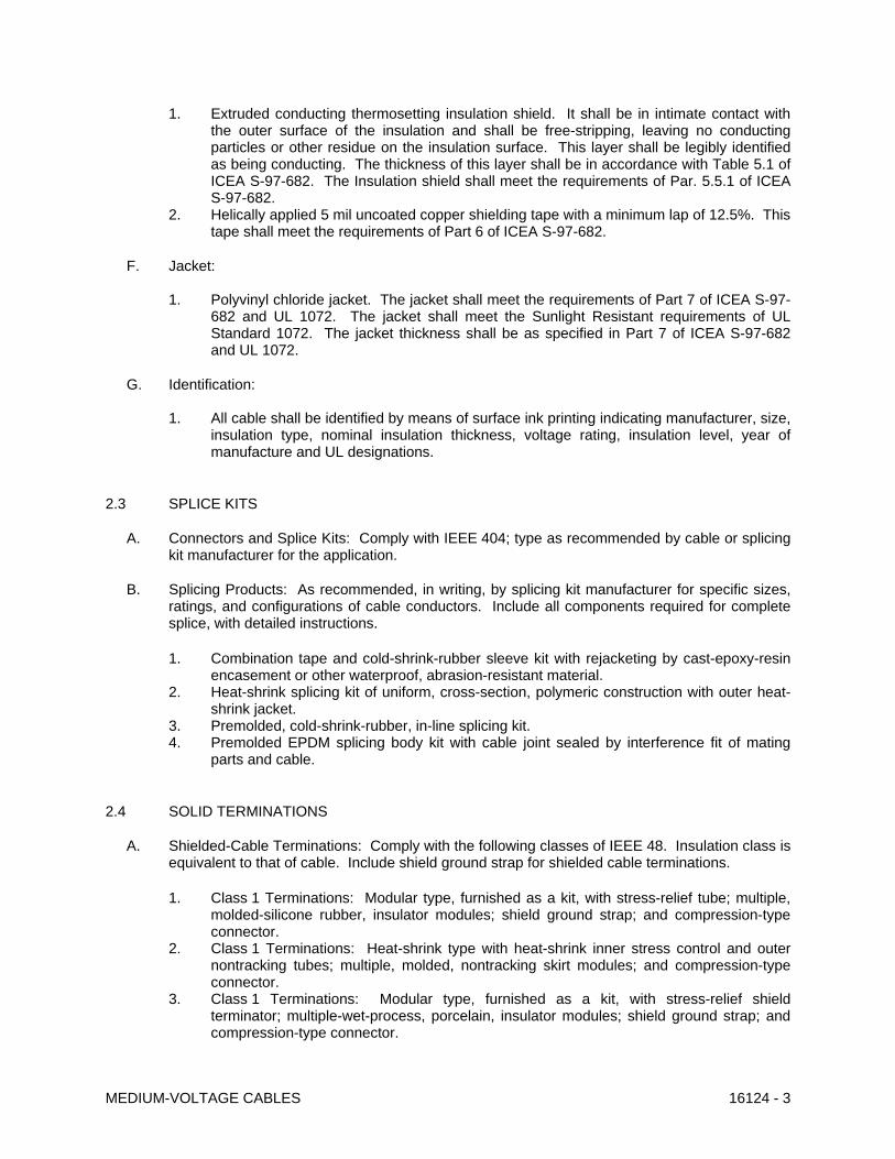
1. Extruded conducting thermosetting insulation shield. It shall be in intimate contact with the outer surface of the insulation and shall be free-stripping, leaving no conducting particles or other residue on the insulation surface. This layer shall be legibly identified as being conducting. The thickness of this layer shall be in accordance with Table 5.1 of ICEA S-97-682. The Insulation shield shall meet the requirements of Par. 5.5.1 of ICEA S-97-682.
2. Helically applied 5 mil uncoated copper shielding tape with a minimum lap of 12.5%. This tape shall meet the requirements of Part 6 of ICEA S-97-682.
F. Jacket:
1. Polyvinyl chloride jacket. The jacket shall meet the requirements of Part 7 of ICEA S-97-682 and UL 1072. The jacket shall meet the Sunlight Resistant requirements of UL Standard 1072. The jacket thickness shall be as specified in Part 7 of ICEA S-97-682 and UL 1072.
G. Identification:
1. All cable shall be identified by means of surface ink printing indicating manufacturer, size, insulation type, nominal insulation thickness, voltage rating, insulation level, year of manufacture and UL designations.
2.3 SPLICE KITS
A. Connectors and Splice Kits: Comply with IEEE 404; type as recommended by cable or splicing kit manufacturer for the application.
B. Splicing Products: As recommended, in writing, by splicing kit manufacturer for specific sizes, ratings, and configurations of cable conductors. Include all components required for complete splice, with detailed instructions.
1. Combination tape and cold-shrink-rubber sleeve kit with rejacketing by cast-epoxy-resin
encasement or other waterproof, abrasion-resistant material. 2. Heat-shrink splicing kit of uniform, cross-section, polymeric construction with outer heat-
shrink jacket. 3. Premolded, cold-shrink-rubber, in-line splicing kit. 4. Premolded EPDM splicing body kit with cable joint sealed by interference fit of mating
parts and cable.
2.4 SOLID TERMINATIONS
A. Shielded-Cable Terminations: Comply with the following classes of IEEE 48. Insulation class is equivalent to that of cable. Include shield ground strap for shielded cable terminations.
1. Class 1 Terminations: Modular type, furnished as a kit, with stress-relief tube; multiple,
molded-silicone rubber, insulator modules; shield ground strap; and compression-type connector.
2. Class 1 Terminations: Heat-shrink type with heat-shrink inner stress control and outer nontracking tubes; multiple, molded, nontracking skirt modules; and compression-type connector.
3. Class 1 Terminations: Modular type, furnished as a kit, with stress-relief shield terminator; multiple-wet-process, porcelain, insulator modules; shield ground strap; and compression-type connector.
MEDIUM-VOLTAGE CABLES 16124 - 3

4. Class 1 Terminations, Indoors: Kit with stress-relief tube, nontracking insulator tube, shield ground strap, compression-type connector, and end seal.
5. Class 2 Terminations, Indoors: Kit with stress-relief tube, nontracking insulator tube, shield ground strap, and compression-type connector. Include silicone-rubber tape, cold-shrink-rubber sleeve, or heat-shrink plastic-sleeve moisture seal for end of insulation whether or not supplied with kits.
6. Class 3 Terminations: Kit with stress cone and compression-type connector.
2.5 ARC-PROOFING MATERIALS
A. Tape for First Course on Metal Objects: 10-mil- thick, corrosion-protective, moisture-resistant, PVC pipe-wrapping tape.
B. Arc-Proofing Tape: Fireproof tape, flexible, conformable, intumescent to 0.3 inch thick, compatible with cable jacket.
C. Glass-Cloth Tape: Pressure-sensitive adhesive type, 1/2 inch wide.
2.6 FAULT INDICATORS
A. Indicators: Manual-reset fault indicator, arranged to clamp to cable sheath and provide a display after a fault has occurred in cable. Instrument shall not be affected by heat, moisture, and corrosive conditions and shall be recommended by manufacturer for installation conditions.
B. Resetting Tool: Designed for use with fault indicators, with moisture-resistant storage and carrying case.
2.7 SOURCE QUALITY CONTROL
A. Test and inspect cables according to NEMA WC 7, UL 1072, AEIC C58 and ICEA S-97-682 before shipping.
B. Test strand-filled cables for water-penetration resistance according to ICEA T-31-610, using a test pressure of 5 psig (35 kPa).
PART 3 - EXECUTION
3.1 INSTALLATION
A. Install cables according to IEEE 576.
B. Pull Conductors: Do not exceed manufacturer's recommended maximum pulling tensions and sidewall pressure values.
1. Where necessary, use manufacturer-approved pulling compound or lubricant that will not deteriorate conductor or insulation.
2. Use pulling means, including fish tape, cable, rope, and basket-weave cable grips that will not damage cables and raceways. Do not use rope hitches for pulling attachment to cable.
MEDIUM-VOLTAGE CABLES 16124 - 4
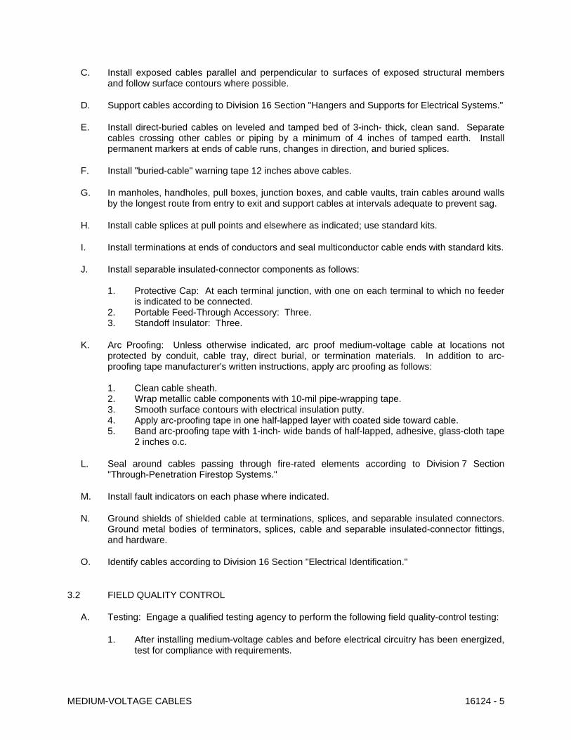
C. Install exposed cables parallel and perpendicular to surfaces of exposed structural members and follow surface contours where possible.
D. Support cables according to Division 16 Section "Hangers and Supports for Electrical Systems."
E. Install direct-buried cables on leveled and tamped bed of 3-inch- thick, clean sand. Separate cables crossing other cables or piping by a minimum of 4 inches of tamped earth. Install permanent markers at ends of cable runs, changes in direction, and buried splices.
F. Install "buried-cable" warning tape 12 inches above cables.
G. In manholes, handholes, pull boxes, junction boxes, and cable vaults, train cables around walls by the longest route from entry to exit and support cables at intervals adequate to prevent sag.
H. Install cable splices at pull points and elsewhere as indicated; use standard kits.
I. Install terminations at ends of conductors and seal multiconductor cable ends with standard kits.
J. Install separable insulated-connector components as follows: 1. Protective Cap: At each terminal junction, with one on each terminal to which no feeder
is indicated to be connected. 2. Portable Feed-Through Accessory: Three. 3. Standoff Insulator: Three.
K. Arc Proofing: Unless otherwise indicated, arc proof medium-voltage cable at locations not protected by conduit, cable tray, direct burial, or termination materials. In addition to arc-proofing tape manufacturer's written instructions, apply arc proofing as follows:
1. Clean cable sheath. 2. Wrap metallic cable components with 10-mil pipe-wrapping tape. 3. Smooth surface contours with electrical insulation putty. 4. Apply arc-proofing tape in one half-lapped layer with coated side toward cable. 5. Band arc-proofing tape with 1-inch- wide bands of half-lapped, adhesive, glass-cloth tape
2 inches o.c.
L. Seal around cables passing through fire-rated elements according to Division 7 Section "Through-Penetration Firestop Systems."
M. Install fault indicators on each phase where indicated.
N. Ground shields of shielded cable at terminations, splices, and separable insulated connectors. Ground metal bodies of terminators, splices, cable and separable insulated-connector fittings, and hardware.
O. Identify cables according to Division 16 Section "Electrical Identification."
3.2 FIELD QUALITY CONTROL
A. Testing: Engage a qualified testing agency to perform the following field quality-control testing:
1. After installing medium-voltage cables and before electrical circuitry has been energized, test for compliance with requirements.
MEDIUM-VOLTAGE CABLES 16124 - 5

MEDIUM-VOLTAGE CABLES 16124 - 6
2. Perform each electrical test and visual and mechanical inspection stated in NETA ATS, Section 7.3.2. Certify compliance with test parameters.
B. Remove malfunctioning cables, replace with new, and retest as specified above.
END OF SECTION 16124

SECTION 16271 – MEDIUM VOLTAGE TRANSFORMERS
PART 1 - GENERAL
1.1 RELATED DOCUMENTS
A. Drawings and general provisions of the Contract, including General and Supplementary Conditions and Division 1 Specification Sections, apply to this Section.
1.2 SUMMARY
A. This Section includes the following types of transformers with medium-voltage primaries: 1. Pad-mounted, liquid-filled transformers.
1.3 SUBMITTALS
A. Product Data: Include rated nameplate data, capacities, weights, dimensions, minimum clearances, installed devices and features, location of each field connection, and performance for each type and size of transformer indicated.
B. Shop Drawings: Wiring and connection diagrams including power signal and control wiring.
C. Qualification Data: For testing agency.
D. Source quality-control test reports.
E. Field quality-control test reports.
F. Follow-up service reports.
G. Operation and Maintenance Data: For transformer and accessories to include in emergency, operation, and maintenance manuals.
1.4 QUALITY ASSURANCE
A. Product Options: Drawings indicate size, profiles, and dimensional requirements of transformers and are based on the specific system indicated. Refer to Division 1 Section "Product Requirements."
B. Electrical Components, Devices, and Accessories: Listed and labeled as defined in Chicago Building Code, Article 100, by a testing agency acceptable to authorities having jurisdiction, and marked for intended use.
C. Comply with IEEE C2.
D. Comply with ANSI C57.12.28, IEEE C57.12.10, IEEE C57.12.70, and IEEE C57.12.80.
E. Comply with City of Chicago Building Code.
MEDIUM-VOLTAGE TRANSFORMERS 16271 - 1

1.5 PROJECT CONDITIONS
A. Service Conditions: IEEE C37.121, usual service conditions except for the following:
1. Exposure to significant solar radiation. 2. Exposure to hot and humid climate or to excessive moisture, including steam, salt spray,
and dripping water. 3. Exposure to excessively high or low temperatures.
1.6 COORDINATION
A. Coordinate size and location of concrete bases. Cast anchor-bolt inserts into bases. Concrete, reinforcement, and formwork requirements are specified in Division 3.
B. Coordinate installation of louvers, doors, spill retention areas, and sumps. Coordinate installation so no piping or conduits are installed in space allocated for medium-voltage transformers except those directly associated with transformers.
PART 2 - PRODUCTS
2.1 MANUFACTURERS
A. Manufacturers: Subject to compliance with requirements, provide products by one of the following: 1. Cutler-Hammer. 2. GE Electrical Distribution & Control. 3. Square D/Groupe Schneider NA.
2.2 PAD-MOUNTED, LIQUID-FILLED TRANSFORMERS
A. Description: ANSI C57.12.13, IEEE C57.12.00, IEEE C57.12.26, pad-mounted, 2-winding transformers. Stainless-steel tank base, cabinet, and sills.
B. Insulating Liquid: Mineral oil, complying with ASTM D 3487, Type II, and tested according to ASTM D 117.
C. Insulation Temperature Rise: 65 deg C when operated at rated kVA output in a 40 deg C ambient temperature. Transformer shall be rated to operate at rated kilovolt ampere in an average ambient temperature of 30 deg C over 24 hours with a maximum ambient temperature of 40 deg C without loss of service life expectancy.
D. Basic Impulse Level: 60kV.
E. Full-Capacity Voltage Taps: Four 2.5 percent taps, 2 above and 2 below rated high voltage; with externally operable tap changer for de-energized use and with position indicator and padlock hasp.
F. High Voltage Switch: 200A, make and latch rating of 10KA RMS, symmetrical, with 3 phase 2 position gang operated, load break switch that is oil immersed in transformer tank with hook stick operating handle in primary compartment.
MEDIUM-VOLTAGE TRANSFORMERS 16271 - 2

G. Primary Fuses: 150-kV fuse assembly with fuses complying with IEEE C37.47. Rating of current-limiting fuses shall be 50-kA RMS at specified system voltage. 1. Bay-O-Net liquid-immersed current-limiting fuses those are externally replaceable without
opening transformer tank.
H. High-Voltage Terminations and Equipment: Dead front with universal-type bushing wells for dead-front bushing-well inserts, complying with IEEE 386 and including the following: 1. Bushing-Well Inserts: One for each high-voltage bushing well. 2. Surge Arresters: Dead-front, elbow-type, metal-oxide-varistor units. 3. Parking Stands: One for each high-voltage bushing well. 4. Portable Insulated Bushings: Arranged for parking insulated, high-voltage, load-break
cable terminators; one for each primary feeder conductor terminating at transformer.
I. Accessories:
1. Drain Valve: 1 inch (25 mm), with sampling device. 2. Dial-type thermometer. 3. Liquid-level gage. 4. Pressure-vacuum gage. 5. Pressure Relief Device: Self-sealing with an indicator.
2.3 IDENTIFICATION DEVICES
A. Nameplates: Engraved, laminated-plastic or metal nameplate for each transformer, mounted with corrosion-resistant screws. Nameplates and label products are specified in Division 16 Section "Electrical Identification."
2.4 SOURCE QUALITY CONTROL
A. Factory Tests: Perform design and routine tests according to standards specified for components. Conduct transformer tests according to IEEE C57.12.90.
B. Factory Tests: Perform the following factory-certified tests on each transformer: 1. Resistance measurements of all windings on rated-voltage connection and on tap
extreme connections. 2. Ratios on rated-voltage connection and on tap extreme connections. 3. Polarity and phase relation on rated-voltage connection. 4. No-load loss at rated voltage on rated-voltage connection. 5. Excitation current at rated voltage on rated-voltage connection. 6. Impedance and load loss at rated current on rated-voltage connection and on tap
extreme connections. 7. Applied potential. 8. Induced potential. 9. Owner will witness all required factory tests. Notify Architect at least 14 days before date
of tests and indicate their approximate duration.
PART 3 - EXECUTION
MEDIUM-VOLTAGE TRANSFORMERS 16271 - 3

3.1 EXAMINATION
A. Examine areas and conditions for compliance with requirements for medium-voltage transformers.
B. Examine roughing-in of conduits and grounding systems to verify the following: 1. Wiring entries comply with layout requirements. 2. Entries are within conduit-entry tolerances specified by manufacturer and no feeders will
have to cross section barriers to reach load or line lugs.
C. Examine walls, floors, roofs, and concrete bases for suitable mounting conditions where transformers will be installed.
D. Verify that ground connections are in place and that requirements in Division 16 Section "Grounding and Bonding" have been met. Maximum ground resistance shall be 5 ohms at location of transformer.
E. Proceed with installation only after unsatisfactory conditions have been corrected.
3.2 INSTALLATION
A. Install transformers on concrete bases.
1. Construct concrete bases of dimensions indicated, but not less than 4 inches larger in both directions than supported unit and 4 inches high.
2. Use 3000-psi, 28-day compressive-strength concrete and reinforcement as specified in Division 3 Section "Cast-in-Place Concrete."
3. Install dowel rods to connect concrete bases to concrete floor. Unless otherwise indicated, install dowel rods on 18-inch centers around full perimeter of base.
4. Install epoxy-coated anchor bolts, for supported equipment, that extend through concrete base and anchor into structural concrete floor.
5. Place and secure anchorage devices. Use supported equipment manufacturer's setting drawings, templates, diagrams, instructions, and directions furnished with items to be embedded.
6. Tack-weld or bolt transformers to channel-iron sills embedded in concrete bases. Install sills level and grout flush with floor or base.
B. Maintain minimum clearances and workspace at equipment according to manufacturer's written instructions and Chicago Building Code.
3.3 IDENTIFICATION
A. Identify field-installed wiring and components and provide warning signs as specified in Division 16 Section "Electrical Identification."
3.4 CONNECTIONS
A. Ground equipment according to Division 16 Section "Grounding and Bonding."
B. Connect wiring according to Division 16 Section "Conductors and Cables."
MEDIUM-VOLTAGE TRANSFORMERS 16271 - 4
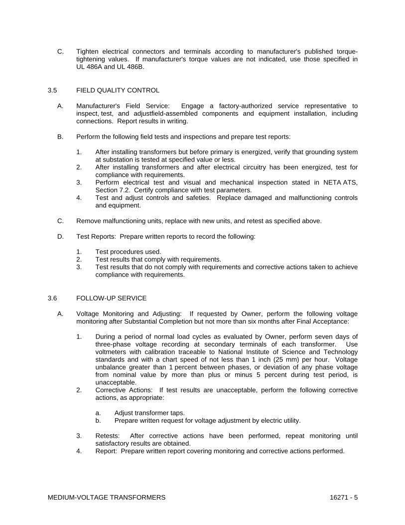
C. Tighten electrical connectors and terminals according to manufacturer's published torque-tightening values. If manufacturer's torque values are not indicated, use those specified in UL 486A and UL 486B.
3.5 FIELD QUALITY CONTROL
A. Manufacturer's Field Service: Engage a factory-authorized service representative to inspect, test, and adjustfield-assembled components and equipment installation, including connections. Report results in writing.
B. Perform the following field tests and inspections and prepare test reports:
1. After installing transformers but before primary is energized, verify that grounding system at substation is tested at specified value or less.
2. After installing transformers and after electrical circuitry has been energized, test for compliance with requirements.
3. Perform electrical test and visual and mechanical inspection stated in NETA ATS, Section 7.2. Certify compliance with test parameters.
4. Test and adjust controls and safeties. Replace damaged and malfunctioning controls and equipment.
C. Remove malfunctioning units, replace with new units, and retest as specified above.
D. Test Reports: Prepare written reports to record the following: 1. Test procedures used. 2. Test results that comply with requirements. 3. Test results that do not comply with requirements and corrective actions taken to achieve
compliance with requirements.
3.6 FOLLOW-UP SERVICE
A. Voltage Monitoring and Adjusting: If requested by Owner, perform the following voltage monitoring after Substantial Completion but not more than six months after Final Acceptance: 1. During a period of normal load cycles as evaluated by Owner, perform seven days of
three-phase voltage recording at secondary terminals of each transformer. Use voltmeters with calibration traceable to National Institute of Science and Technology standards and with a chart speed of not less than 1 inch (25 mm) per hour. Voltage unbalance greater than 1 percent between phases, or deviation of any phase voltage from nominal value by more than plus or minus 5 percent during test period, is unacceptable.
2. Corrective Actions: If test results are unacceptable, perform the following corrective actions, as appropriate: a. Adjust transformer taps. b. Prepare written request for voltage adjustment by electric utility.
3. Retests: After corrective actions have been performed, repeat monitoring until
satisfactory results are obtained. 4. Report: Prepare written report covering monitoring and corrective actions performed.
MEDIUM-VOLTAGE TRANSFORMERS 16271 - 5

MEDIUM-VOLTAGE TRANSFORMERS 16271 - 6
END OF SECTION 16271

SECTION 16341 - MEDIUM-VOLTAGE SWITCHGEAR
PART 1 - GENERAL
1.1 RELATED DOCUMENTS
A. Drawings and general provisions of the Contract, including General and Supplementary Conditions and Division 1 Specification Sections, apply to this Section.
1.2 SUMMARY
A. This Section includes metal-enclosed interrupter switchgear with the following optional components, features, and accessories:
1. Copper, tin-plated main bus. 2. Analog instruments. 3. Surge arresters.
1.3 DEFINITIONS
A. ATS: Acceptance Testing Specifications.
B. GFCI: Ground-Fault Circuit Interrupter.
1.4 SUBMITTALS
A. Product Data: For each type of switchgear and related equipment, include the following:
1. Rated capacities, operating characteristics, furnished specialties, and accessories for individual interrupter switches
2. Time-current characteristic curves for overcurrent protective devices, including fusible devices.
B. Shop Drawings: For each type of switchgear and related equipment, include the following:
1. Dimensioned plans, elevations, sections, and details, including required clearances and service space around equipment. Show method of field assembly and location and size of each field connection. Include the following:
a. Tabulation of installed devices with features and ratings. b. Outline and general arrangement drawing showing dimensions, shipping sections,
and weights of each assembled section. c. Drawing of cable termination compartments showing preferred locations for
conduits and indicating space available for cable terminations. d. Pad drawing showing locations for anchor bolts. e. Current ratings of buses. f. Short-time and short-circuit ratings of switchgear assembly. g. Nameplate legends.
MEDIUM-VOLTAGE SWITCHGEAR 16341 - 1

2. Wiring Diagrams: For switchgear and related equipment, include the following:
a. Power, signal, and control wiring. b. Three-line diagrams of current and future secondary circuits showing device
terminal numbers and internal diagrams. c. Schematic control diagrams. d. Diagrams showing connections of component devices and equipment.
C. Coordination Drawings: Installation plans showing dimensioned layout, required working and safety clearances. Show switchgear layout and relationships between components and adjacent elements. Identify field measurements.
D. Source quality-control test reports.
E. Field quality-control test reports.
F. Operation and Maintenance Data: For switchgear and switchgear components to include in emergency, operation, and maintenance manuals. In addition to items specified in Division 1 Section "Operation and Maintenance Data," include the following:
1. Manufacturer's written instructions for testing and adjusting overcurrent protective devices.
2. Time-current curves, including selectable ranges for each type of overcurrent protective device.
1.5 QUALITY ASSURANCE
A. Source Limitations: Obtain each type of switchgear and associated components through one source from a single manufacturer.
B. Product Options: Drawings indicate size, profiles, and dimensional requirements of switchgear and are based on the specific system indicated. Refer to Division 1 Section "Product Requirements."
C. Electrical Components, Devices, and Accessories: Listed and labeled as defined in CCBC Chicago Electrical Code, Article 100, by a testing agency acceptable to authorities having jurisdiction, and marked for intended use.
D. Comply with IEEE C2.
1.6 DELIVERY, STORAGE, AND HANDLING
A. Store switchgear indoors in clean dry space with uniform temperature to prevent condensation. Protect switchgear from exposure to dirt, fumes, water, corrosive substances, and physical damage.
B. If stored in areas subjected to weather, cover switchgear to provide protection from weather, dirt, dust, corrosive substances, and physical damage. Remove loose packing and flammable materials from inside switchgear; install electric heating (250 W per section) to prevent condensation.
MEDIUM-VOLTAGE SWITCHGEAR 16341 - 2

1.7 PROJECT CONDITIONS
A. Environmental Limitations: Rate equipment for continuous operation at indicated ampere ratings for the following conditions:
1. Ambient temperature not exceeding 122 deg F. 2. Altitude of 1000 ft above sea level. 3. Installation next to large body of water (Lake Michigan), High humidity corrosive
environment.
B. Interruption of Existing Electrical Service: Do not interrupt electrical service to facilities occupied by Owner or others unless permitted under the following conditions and then only after arranging to provide temporary electrical service according to requirements indicated:
1. Notify CPD representative no fewer than 10 (ten) working days in advance of proposed interruption of electrical service.
2. Do not proceed with interruption of electrical service without CPD representative written permission.
1.8 COORDINATION
A. Coordinate layout and installation of switchgear and components with other construction on site. and adjacent surfaces. Maintain required clearances for workspace and equipment access path.
B. Re-use existing concrete base.
1.9 EXTRA MATERIALS
A. Furnish extra materials described below that match products installed and that are packaged with protective covering for storage and identified with labels describing contents.
1. Fuses: Three of type and rating used. Include spares for future transformers, control power circuits, and fusible devices.
2. Indicating Lights: Three of each type installed. 3. Touchup Paint: One container of paint matching enclosure finish, 0.5 pint .
B. Maintenance Tools: Furnish tools and miscellaneous items required for interrupter switchgear test, inspection, maintenance, and operation. Include the following:
1. Fuse-handling tool.
PART 2 - PRODUCTS
2.1 MANUFACTURERS
1. Manufacturers: Subject to compliance with requirements, provide products by one of the manufacturers specified.
MEDIUM-VOLTAGE SWITCHGEAR 16341 - 3

2.2 MANUFACTURED UNITS
A. Description: Factory assembled and tested, and complying with IEEE C37.20.1.
B. Ratings: Suitable for application in 3-phase, 60-Hz, solidly grounded-neutral system.
C. System Voltage: 4.16 kV nominal; 4.76 kV maximum
2.3 METAL-ENCLOSED INTERRUPTER SWITCHGEAR
A. Manufacturers:
1. S&C Electric Company, Pad mounted switchgear.
B. Comply with IEEE C37.20.3.
C. Comply with ANSI C57.12.28 for enclosure integrity for pad mounted equipment.
D. Comply with Art. 490.21 of the CEC.
E. Design Level of Available-Source Fault Current: Integrated short-circuit rating consistent with value of fault current indicated.
F. Ratings: Comply with standard ratings designated in IEEE C37.20.3 for maximum-rated voltage specified.
1. Main-Bus Rating: 600 A, continuous.
G. Interrupter Switches: Stationary, gang operated, and suitable for application at maximum short-circuit rating of integrated switchgear assembly.
1. Duty-Cycle, Fault Closing: 25,000 asymmetrical A. 2. Switch Action: Quick make-quick break mechanism. No external arc and no significant
quantities of ionized gas released into the enclosure. 3. Switch Construction: Supported entirely by interior framework of structure, with copper
switchblades and stored-energy operating mechanism. 4. Phase Barriers: Full length of switchblades and fuses for each pole; designed for easy
removal; allow visual inspection of switch components if barrier is in place. 5. Protective Shields: Cover live components and terminals. 6. Fuses: De-energized if switch is open.
H. Mechanical Interlock: Prevent opening switch compartment door unless switchblades are open, and prevent closing switch if door is open.
I. Window: Permit viewing switchblade positions if door is closed.
J. Interrupter switches in combination with power fuses shall safely withstand the effects of closing, carrying, and interrupting all possible currents up to the assigned maximum short circuit rating.
K. Power Fuses: Comply with the following and with applicable requirements in NEMA SG 2:
1. Indicator: Integral with each fuse to indicate when it has blown.
MEDIUM-VOLTAGE SWITCHGEAR 16341 - 4

2. Mounting: Positively held in position with provision for easy removal and replacement from front without special tools.
3. Current-Limiting Fuses: Full-range, fast-replaceable, current-limiting type that will operate without explosive noise or expulsion of gas, vapor, or foreign matter from tube.
2.4 FABRICATION
A. Outdoor Enclosure: Galvanized steel, weatherproof construction; integral structural-steel base frame with factory-applied asphaltic undercoating.
To guard against corrosion due to extremely harsh environmental conditions, the entire exterior of the enclosure shall be fabricated from 11-gauge Type 304 stainless steel.
1. Each compartment shall have the following features:
a. Structural design and anchorage adequate to resist loads imposed by 125-mph wind.
b. Space heater operating at one-half or less of rated voltage, sized to prevent condensation.
c. Louvers equipped with insect and rodent screen and filter, and arranged to permit air circulation while excluding rodents and exterior dust.
d. Hinged front door with locking provisions. e. Interior light with switch. f. Weatherproof GFCI duplex receptacle. g. Power for heaters, lights, and receptacles to be provided by control power
transformer.
B. Finish: Manufacturer's standard gray finish over rust-inhibiting primer on phosphatizing-treated metal surfaces.
C. Outgoing Feeder Units: Arranged to suit distribution feeders.
D. Key Interlocks: Arranged to effect interlocking schemes indicated.
E. Each set of doors shall be equipped with automatic three point latching mechanism with padlocking provision..
F. Full-length steel barriers shall separate side-by-side compartments.
G. Provide dual-purpose front barriers. The barriers, in their normal hanging positions, shall guard against inadvertent contact with live parts. It shall also be possible to lift these barriers out and insert them into the open gap when the switch is open. These barriers shall meet the requirements of Section 381G of the National Electrical Safety Code (ANSI Standard C2).
H. Each fuse shall be provided with a dual-purpose front barrier. These barriers, in their normal hanging positions, shall guard against inadvertent contact with live parts. It shall also be possible to lift these barriers out and insert them into the open gaps when the fuses are in the disconnect position. These barriers shall meet the requirements of Section 381G of the National Electrical Safety Code (ANSI Standard C2).
MEDIUM-VOLTAGE SWITCHGEAR 16341 - 5

2.5 COMPONENTS
A. Main Bus: Copper, silver plated at connection points Copper, tin plated; full length of switchgear.
B. Ground Bus: Copper, silver plated or copper, tin plated; minimum size 1/4 by 2 inches ; full length of switchgear.
C. Bus Insulation: Covered with flame-retardant insulation.
D. Surge Arresters: Distribution class, metal-oxide-varistor type. Comply with NEMA LA 1.
1. Install in cable termination compartments in each phase of circuit. 2. Coordinate rating with circuit voltage.
2.6 IDENTIFICATION
A. Materials: Refer to Division 16 Section "Electrical Identification." Identify units, devices, controls, and wiring.
2.7 SOURCE QUALITY CONTROL
A. Assemble switchgear and equipment in manufacturer's plant and perform all functional tests.
B. Prepare equipment for shipment.
1. Provide suitable crating, blocking, and supports so equipment will withstand expected domestic shipping and handling shocks and vibration.
2. Weatherproof equipment for shipment. Close connection openings to prevent entrance of foreign material during shipment and storage.
2.8 FACTORY FINISHES
A. Finish: Manufacturer's standard color finish applied to equipment before shipping.
PART 3 - EXECUTION
3.1 EXAMINATION
A. Examine elements and surfaces to receive switchgear for compliance with requirements for installation tolerances, required clearances, and other conditions affecting performance.
1. Proceed with installation only after unsatisfactory conditions have been corrected.
3.2 INSTALLATION
A. Anchor switchgear assembly to existing concrete base and attach by bolting.
MEDIUM-VOLTAGE SWITCHGEAR 16341 - 6

B. Temporary Lifting Provisions: Remove temporary lifting eyes, channels, and brackets and temporary blocking of moving parts from switchgear units and components.
3.3 IDENTIFICATION
A. Identify field-installed conductors, interconnecting wiring, and components; provide warning signs as specified in Division 16 Section "Electrical Identification."
3.4 CONNECTIONS
A. Cable terminations at switchgear are specified in Division 16 Section "Medium-Voltage Cables."
B. Tighten bus joints, electrical connectors, and terminals according to manufacturer's published torque-tightening values.
C. Ground equipment according to Division 16 Section "Grounding and Bonding."
D. Connect wiring according to Division 16 Sections "Conductors and Cables" and "Medium-Voltage Cables."
3.5 FIELD QUALITY CONTROL
A. Prepare for acceptance tests as follows:
1. Test insulation resistance for each switchgear bus, component, connecting supply, feeder, and control circuit.
2. Test continuity of each circuit.
B. Manufacturer's Field Service: Engage a factory-authorized service representative to perform the following:
1. Inspect switchgear, wiring, components, connections, and equipment installation. 2. Report results in writing.
C. Perform the following field tests and inspections and prepare test reports:
1. Perform each electrical test and visual and mechanical inspection stated in NETA ATS. Certify compliance with test parameters. Perform NETA tests and inspections for each of the following NETA categories:
a. Switchgear. b. Surge arresters.
D. Remove and replace malfunctioning units and retest as specified above.
3.6 CLEANING
A. On completion of installation, inspect interior and exterior of switchgear. Vacuum dirt and debris; do not use compressed air to assist in cleaning. Repair damaged finishes.
MEDIUM-VOLTAGE SWITCHGEAR 16341 - 7

MEDIUM-VOLTAGE SWITCHGEAR 16341 - 8
3.7 PROTECTION
A. Temporary Heating: Apply temporary heat to switchgear, according to manufacturer's written instructions, throughout periods when switchgear environment is not controlled for temperature and humidity within manufacturer's stipulated service conditions.
3.8 DEMONSTRATION
A. Train Owner's maintenance personnel to adjust, operate, and maintain switchgear. Refer to Division 1 Section "Demonstration and Training."
END OF SECTION 16341