pss 4000 emergency stop with pitestop instruction list...pss 4000 emergency stop with pitestop...
TRANSCRIPT

PSS 4000 Emergency Stop with PITestop
Instruction List
Product
Type: FS_EmergencyStop, FS_OutputFBL
Name: PSS 4000, Blocks, PAS4000, PLC, IL
Manufacturer: Pilz GmbH & Co. KG, Safe Automation
Document
Release Number: 05
Release Date: 20 April 2012
Application Note - No. 1002023_EN_05

14 pt
28 pt
42 pt
56 pt
70 pt
84 pt
98 pt
112 pt
126 pt
140 pt
154 pt
168 pt
182 pt
196 pt
210 pt
224 pt
238 pt
252 pt
266 pt
280 pt
294 pt
308 pt
322 pt
336 pt
350 pt
364 pt
378 pt
392 pt
406 pt
420 pt
434 pt
448 pt
462 pt
476 pt
490 pt
504 pt
518 pt
532 pt
546 pt
560 pt
574 pt
588 pt
602 pt
616 pt
630 pt
644 pt
658 pt
672 pt
686 pt
700 pt
714 pt
728 pt
742 pt
756 pt
770 pt
784 pt
798 pt
812 pt
826 pt
Application Note – No. 1002023_EN_05
PSS 4000 Emergency Stop with PITestop Instruction List
Pilz GmbH & Co. KG, Felix-Wankel-Straße 2, 73760 Ostfildern, Germany 2/26 Telephone: +49 711 3409-0, Telefax: +49 711 3409-133, E-Mail: [email protected]
Document Revision History
Release Date Changes Chapter
01 2010-04-08 Creation all
02 2010-09-28 Adjustments for publication on Pilz website, only editorial,
03 2011-01-04 Adjustments for publication on Pilz website only editorial
04 2011-07-27 Revision for Pilz Automation Suite all
05 2012-04-20 Revision of the Application Note all
Exclusion of liability
We have taken great care in compiling our application note. It contains information about our
company and our products. All statements are made in accordance with the current status of
technology and to the best of our know-ledge and belief.
However, we cannot accept liability for the accuracy and entirety of the information provided,
except in the case of gross negligence. In particular it should be noted that statements do not
have the legal quality of assurances or assured properties.
We are grateful for any feedback on the contents.
April 2012
All rights to this publication are reserved by Pilz GmbH & Co. KG. We reserve the right to
amend specifications without prior notice. Copies may be made for the user’s internal purposes.
The names of products, goods and technologies used in this manual are trademarks of the
respective companies.

14 pt
28 pt
42 pt
56 pt
70 pt
84 pt
98 pt
112 pt
126 pt
140 pt
154 pt
168 pt
182 pt
196 pt
210 pt
224 pt
238 pt
252 pt
266 pt
280 pt
294 pt
308 pt
322 pt
336 pt
350 pt
364 pt
378 pt
392 pt
406 pt
420 pt
434 pt
448 pt
462 pt
476 pt
490 pt
504 pt
518 pt
532 pt
546 pt
560 pt
574 pt
588 pt
602 pt
616 pt
630 pt
644 pt
658 pt
672 pt
686 pt
700 pt
714 pt
728 pt
742 pt
756 pt
770 pt
784 pt
798 pt
812 pt
826 pt
Application Note – No. 1002023_EN_05
PSS 4000 Emergency Stop with PITestop Instruction List
Pilz GmbH & Co. KG, Felix-Wankel-Straße 2, 73760 Ostfildern, Germany 3/26 Telephone: +49 711 3409-0, Telefax: +49 711 3409-133, E-Mail: [email protected]
Support
Technical help round the clock!
Technical support is available from Pilz round the clock.
This service is provided free of charge beyond standard business hours.
Americas
� Brazil
+55 11 8245-8267
� Mexico
+52 55 5572 1300
� USA (toll free)
+1 877-PILZUSA (745-9872)
Asia
� China
+86 21 62494658-216
� Japan
+81 45 471-2281
� Korea
+82 2 2263 9540
Australia
� Australia
+61 3 95446300
Europe
� Austria
+43 1 7986263-0
� Belgium, Luxembourg
+32 9 3217575
� England
+44 1536 462203
� France
+33 3 88104000
� Germany
+49 711 3409-444
� Ireland
+353 21 4804983
� Italy
+39 031 789511
� Scandinavia
+45 74436332
� Spain
+34 938497433
� Switzerland
+41 62 88979-30
� The Netherlands
+31 347 320477
� Turkey
+90 216 5775552
You can reach our international hotline on:
+49 711 3409-444 or mailto:[email protected]
Pilz GmbH & Co. KG
Safe Automation
Felix-Wankel-Straße 2
73760 Ostfildern, Germany
Telephone: +49 711 3409-0
Telefax: +49 711 3409-133
E-Mail: [email protected]
Internet: www.pilz.com

14 pt
28 pt
42 pt
56 pt
70 pt
84 pt
98 pt
112 pt
126 pt
140 pt
154 pt
168 pt
182 pt
196 pt
210 pt
224 pt
238 pt
252 pt
266 pt
280 pt
294 pt
308 pt
322 pt
336 pt
350 pt
364 pt
378 pt
392 pt
406 pt
420 pt
434 pt
448 pt
462 pt
476 pt
490 pt
504 pt
518 pt
532 pt
546 pt
560 pt
574 pt
588 pt
602 pt
616 pt
630 pt
644 pt
658 pt
672 pt
686 pt
700 pt
714 pt
728 pt
742 pt
756 pt
770 pt
784 pt
798 pt
812 pt
826 pt
Application Note – No. 1002023_EN_05
PSS 4000 Emergency Stop with PITestop Instruction List
Pilz GmbH & Co. KG, Felix-Wankel-Straße 2, 73760 Ostfildern, Germany 4/26 Telephone: +49 711 3409-0, Telefax: +49 711 3409-133, E-Mail: [email protected]
Contents
1. Useful documentation .................................................................................. 6 1.1. Documentation from Pilz GmbH & Co. KG ............................................................................ 6
1.2. Documentation from other sources of information ................................................................. 6
2. Hardware configuration ................................................................................ 7 2.1. Pilz products ........................................................................................................................... 7
2.2. Hardware configuration .......................................................................................................... 7
3. Application Task ........................................................................................... 8 3.1. Description ............................................................................................................................. 8
3.1.1. Emergency stop function ............................................................................................. 8
3.1.2. Feedback loop monitoring function ............................................................................ 10
3.2. Functional safety .................................................................................................................. 11
3.2.1. Safety-related characteristics in accordance with EN ISO 13849-1 .......................... 11
3.2.2. Safety-related characteristics in accordance with EN 62061 .................................... 12
3.3. PAS-Project .......................................................................................................................... 13
3.3.1. IEC 61131 Programming ........................................................................................... 13
3.3.2. I/O Mapping ............................................................................................................... 17
3.3.3. Process PAS Project ................................................................................................. 18
3.4. Circuit diagram of the application ......................................................................................... 21
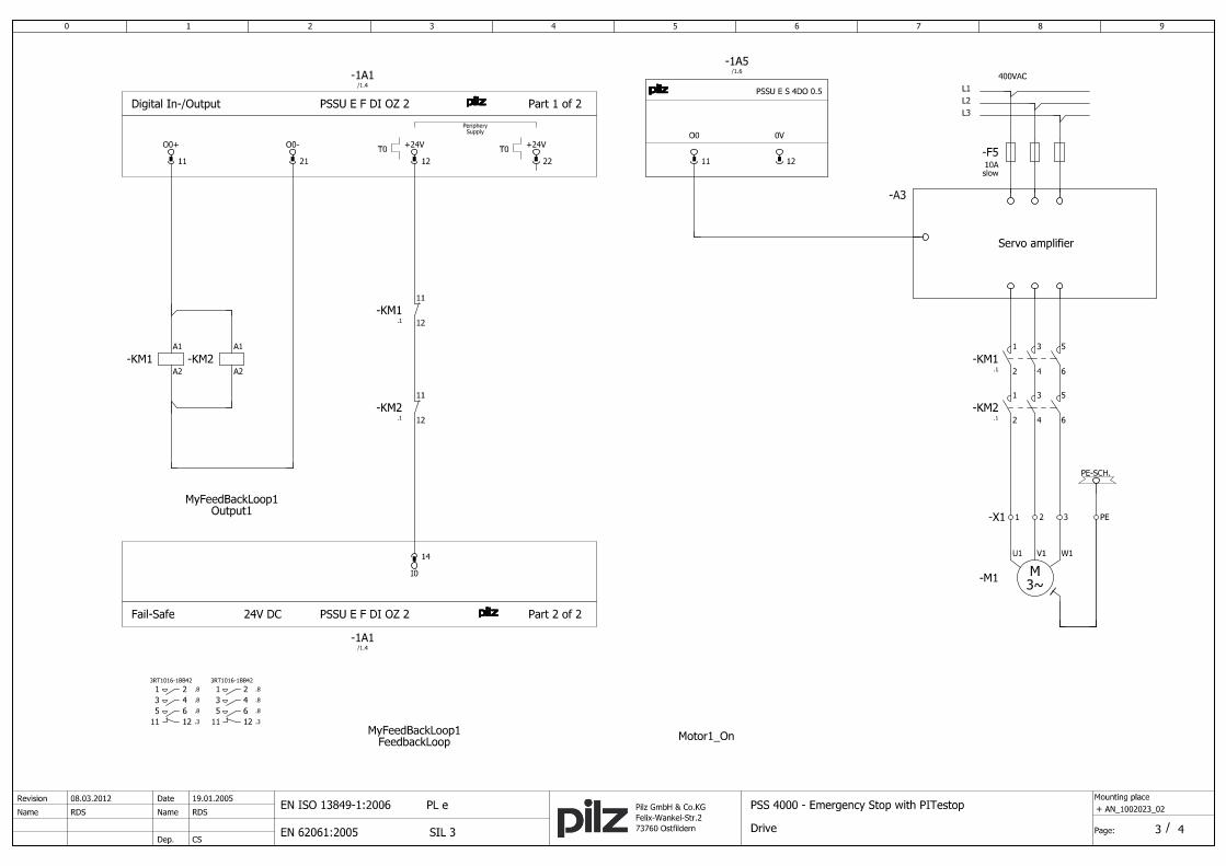
3.4.1. Circuit diagram 1/4 ..................................................................................................... 21
3.4.2. Circuit diagram 2/4 ..................................................................................................... 22
3.4.3. Circuit diagram 3/4 ..................................................................................................... 23
3.4.4. Circuit diagram 4/4 ..................................................................................................... 24
4. Table of figures ........................................................................................... 25

14 pt
28 pt
42 pt
56 pt
70 pt
84 pt
98 pt
112 pt
126 pt
140 pt
154 pt
168 pt
182 pt
196 pt
210 pt
224 pt
238 pt
252 pt
266 pt
280 pt
294 pt
308 pt
322 pt
336 pt
350 pt
364 pt
378 pt
392 pt
406 pt
420 pt
434 pt
448 pt
462 pt
476 pt
490 pt
504 pt
518 pt
532 pt
546 pt
560 pt
574 pt
588 pt
602 pt
616 pt
630 pt
644 pt
658 pt
672 pt
686 pt
700 pt
714 pt
728 pt
742 pt
756 pt
770 pt
784 pt
798 pt
812 pt
826 pt
Application Note – No. 1002023_EN_05
PSS 4000 Emergency Stop with PITestop Instruction List
Pilz GmbH & Co. KG, Felix-Wankel-Straße 2, 73760 Ostfildern, Germany 5/26 Telephone: +49 711 3409-0, Telefax: +49 711 3409-133, E-Mail: [email protected]
Abbreviations
PAS Pilz Automation Suite (software platform)
PSS Programmable control system (DE: Programmierbares Steuerungssystem)
PNOZ Pilz E-STOP Positive-guided (DE: Pilz NOT-AUS-Zwangsgeführt)
POU Program Organisation Unit
PRG Program
FB Function Block
FUN Function
IL Instruction List

14 pt
28 pt
42 pt
56 pt
70 pt
84 pt
98 pt
112 pt
126 pt
140 pt
154 pt
168 pt
182 pt
196 pt
210 pt
224 pt
238 pt
252 pt
266 pt
280 pt
294 pt
308 pt
322 pt
336 pt
350 pt
364 pt
378 pt
392 pt
406 pt
420 pt
434 pt
448 pt
462 pt
476 pt
490 pt
504 pt
518 pt
532 pt
546 pt
560 pt
574 pt
588 pt
602 pt
616 pt
630 pt
644 pt
658 pt
672 pt
686 pt
700 pt
714 pt
728 pt
742 pt
756 pt
770 pt
784 pt
798 pt
812 pt
826 pt
Application Note – No. 1002023_EN_05
PSS 4000 Emergency Stop with PITestop Instruction List
Pilz GmbH & Co. KG, Felix-Wankel-Straße 2, 73760 Ostfildern, Germany 6/26 Telephone: +49 711 3409-0, Telefax: +49 711 3409-133, E-Mail: [email protected]
1. Useful documentation
Reading the documentation listed below is necessary for understanding this application note.
The availability of the indicated tools and safe handling are also presupposed with the user.
1.1. Documentation from Pilz GmbH & Co. KG
No. Description Item No.
1 Pilz international homepage, download section www.pilz.com
2 Operating Manual PSSu H PLC1 FS SN SD 21939-EN-xx
3 Operating Manual PSSu E F 4DI 21 311-xx
4 Operating Manual PSSu E F DI OZ 2 21 329-xx
5 Operating Manual PSSu E F 4DO 0.5 21 317-xx
6 Operating Manual PSSu E S 4DI 21 340-EN-xx
7 Operating Manual PSSu E S 4DO 0.5 21 346-EN-xx
8 System Description Programmable safety and control system PSS 4000 1001 467-EN-xx
9 Safety Manual Programmable safety and control system PSS 4000 1001 468-EN-xx
10 PAS4000 online help -
11 Operating instructions PITestop 21 136-xx
1.2. Documentation from other sources of information
No. Description Item No.
1
2
Note
The present example (PSS 4000 Emergency Stop with PITestop) is also available in the
programming languages Structured text and PASmulti.

14 pt
28 pt
42 pt
56 pt
70 pt
84 pt
98 pt
112 pt
126 pt
140 pt
154 pt
168 pt
182 pt
196 pt
210 pt
224 pt
238 pt
252 pt
266 pt
280 pt
294 pt
308 pt
322 pt
336 pt
350 pt
364 pt
378 pt
392 pt
406 pt
420 pt
434 pt
448 pt
462 pt
476 pt
490 pt
504 pt
518 pt
532 pt
546 pt
560 pt
574 pt
588 pt
602 pt
616 pt
630 pt
644 pt
658 pt
672 pt
686 pt
700 pt
714 pt
728 pt
742 pt
756 pt
770 pt
784 pt
798 pt
812 pt
826 pt
Application Note – No. 1002023_EN_05
PSS 4000 Emergency Stop with PITestop Instruction List
Pilz GmbH & Co. KG, Felix-Wankel-Straße 2, 73760 Ostfildern, Germany 7/26 Telephone: +49 711 3409-0, Telefax: +49 711 3409-133, E-Mail: [email protected]
2. Hardware configuration
2.1. Pilz products
No. Description Order number Version Number
1 PSSu H PLC1 FS SN SD 312 070 001 1
2 PSSu E F 4DI 312 200 - 1
3 PSSu E F DI OZ 2 312 220 - 1
4 PSSu E F 4DO 0.5 312 210 - 2
5 PSSu E S 4DI 312 400 - 1
6 PSSu E S 4DO 0.5 312 405 - 1
7 PSSu BP 1/8 C 312 601 - 6
8 PITestop Set 1.1 400 410 - 1
9 PAS4000 - v1.5.0 1
2.2. Hardware configuration
Fig. 1: Hardware configuration

14 pt
28 pt
42 pt
56 pt
70 pt
84 pt
98 pt
112 pt
126 pt
140 pt
154 pt
168 pt
182 pt
196 pt
210 pt
224 pt
238 pt
252 pt
266 pt
280 pt
294 pt
308 pt
322 pt
336 pt
350 pt
364 pt
378 pt
392 pt
406 pt
420 pt
434 pt
448 pt
462 pt
476 pt
490 pt
504 pt
518 pt
532 pt
546 pt
560 pt
574 pt
588 pt
602 pt
616 pt
630 pt
644 pt
658 pt
672 pt
686 pt
700 pt
714 pt
728 pt
742 pt
756 pt
770 pt
784 pt
798 pt
812 pt
826 pt
Application Note – No. 1002023_EN_05
PSS 4000 Emergency Stop with PITestop Instruction List
Pilz GmbH & Co. KG, Felix-Wankel-Straße 2, 73760 Ostfildern, Germany 8/26 Telephone: +49 711 3409-0, Telefax: +49 711 3409-133, E-Mail: [email protected]
3. Application Task
3.1. Description
The example shows the implementation of an emergency stop application with a PSS 4000
PLC.
The safe control and evaluation of the signals is taken over by two Pilz Function blocks (FS-FB)
from the library.
� FS_EmergencyStop
- CRC EA57
� FS_OutputFBL
- CRC B3A7
The workflow is divided into the following two main functions:
� Emergency Stop and
� Feedback Loop Monitoring
3.1.1. Emergency stop function
The control system monitors the emergency stop button (S1) via the user program. An instance
of the Pilz Function block “FS_EmergencyStop” is assigned to them. This FS-FB detects
whether the assigned emergency stop button has been operated, as well as detecting incorrect
input signals and whether the contact synchronization time has been exceeded, etc.
If the emergency stop button (S1) is operated or an error occurs, the enable output “Enable” on
the FS-FB will immediately be reset.
The enable output “Enable” is also reset when the PSS is stopped and when the PSS is
switched on. The signal from the enable output “Enable” must be evaluated by the user program
and trigger an appropriate reaction.
Based on the diagnostic outputs (“DiagSwitchError”, “DiagInputNotValid”) it can be determined
why “Enable” was reset.
The outputs “DiagOperated”, “DiagReadyForReset” and “DiagReadyForTest” are used as status
messages.
A “valid bit” is formed by the system for the respective hardware input to determine whether a
process value received from a sensor is valid.
The valid bit is queried in the Function block and indicates whether an error has occurred in the
signal transmission between hardware input and processor (such as test clock error, module
overheats, etc.).
If the valid bit is FALSE, the process value is invalid and the Pilz function block provides an
appropriate diagnostic message. The error signal reset enable.
(For more information, see “Validity of process data” in PAS4000 online help)

14 pt
28 pt
42 pt
56 pt
70 pt
84 pt
98 pt
112 pt
126 pt
140 pt
154 pt
168 pt
182 pt
196 pt
210 pt
224 pt
238 pt
252 pt
266 pt
280 pt
294 pt
308 pt
322 pt
336 pt
350 pt
364 pt
378 pt
392 pt
406 pt
420 pt
434 pt
448 pt
462 pt
476 pt
490 pt
504 pt
518 pt
532 pt
546 pt
560 pt
574 pt
588 pt
602 pt
616 pt
630 pt
644 pt
658 pt
672 pt
686 pt
700 pt
714 pt
728 pt
742 pt
756 pt
770 pt
784 pt
798 pt
812 pt
826 pt
Application Note – No. 1002023_EN_05
PSS 4000 Emergency Stop with PITestop Instruction List
Pilz GmbH & Co. KG, Felix-Wankel-Straße 2, 73760 Ostfildern, Germany 9/26 Telephone: +49 711 3409-0, Telefax: +49 711 3409-133, E-Mail: [email protected]
The way in which the error is reset will depend on the operating mode set on the FS-FB.
In this application example, parameters for FS-FB have been set in such a way that “Reset”
(S3) is required in order to reset output parameter “Enable” when:
- the PSS is cold started (PSS switched from off to on),
- warm started (PSS transferring from STOP to RUN) or
- when the emergency stop button (S1) is released.
Although the emergency stop functions are configured to reset themselves, a PSS cold start or
the release of an emergency stop button that has been operated may not directly enable a
machine to start up without further conditions being met.
Input circuit safety assessment
� If a contact on the emergency stop button is overridden, the Pilz function block will detect this
as an error at the next operation.
� A short between the input circuits within a multicore cable will be detected as an error by the
programmable control system.
� A short between 24 VDC and an input circuit will be detected as an error by the
programmable control system.
� The highest category can only be achieved when the contacts on the E-STOP pushbutton are
supplied with test pulses and the E-STOP pushbutton has dual-channel wiring.
� If an operator completely (or even maybe partly) is able to access the dangerous area, a risk
analysis should clarify whether an additional, separate “manual reset function” is required.
14 pt
28 pt
42 pt
56 pt
70 pt
84 pt
98 pt
112 pt
126 pt
140 pt
154 pt
168 pt
182 pt
196 pt
210 pt
224 pt
238 pt
252 pt
266 pt
280 pt
294 pt
308 pt
322 pt
336 pt
350 pt
364 pt
378 pt
392 pt
406 pt
420 pt
434 pt
448 pt
462 pt
476 pt
490 pt
504 pt
518 pt
532 pt
546 pt
560 pt
574 pt
588 pt
602 pt
616 pt
630 pt
644 pt
658 pt
672 pt
686 pt
700 pt
714 pt
728 pt
742 pt
756 pt
770 pt
784 pt
798 pt
812 pt
826 pt
Application Note – No. 1002023_EN_05
PSS 4000 Emergency Stop with PITestop Instruction List
Pilz GmbH & Co. KG, Felix-Wankel-Straße 2, 73760 Ostfildern, Germany 10/26 Telephone: +49 711 3409-0, Telefax: +49 711 3409-133, E-Mail: [email protected]
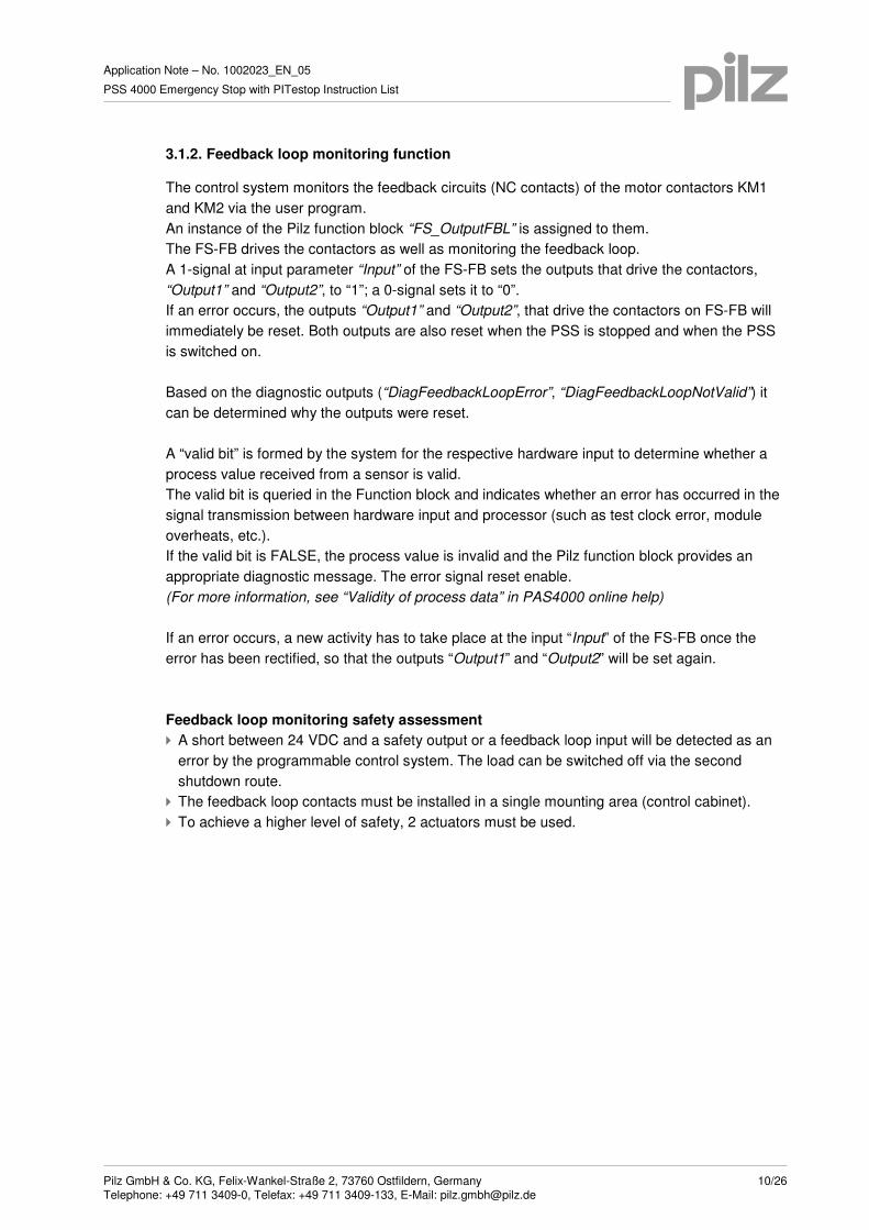
3.1.2. Feedback loop monitoring function
The control system monitors the feedback circuits (NC contacts) of the motor contactors KM1
and KM2 via the user program.
An instance of the Pilz function block “FS_OutputFBL” is assigned to them.
The FS-FB drives the contactors as well as monitoring the feedback loop.
A 1-signal at input parameter “Input” of the FS-FB sets the outputs that drive the contactors,
“Output1” and “Output2”, to “1”; a 0-signal sets it to “0”.
If an error occurs, the outputs “Output1” and “Output2”, that drive the contactors on FS-FB will
immediately be reset. Both outputs are also reset when the PSS is stopped and when the PSS
is switched on.
Based on the diagnostic outputs (“DiagFeedbackLoopError”, “DiagFeedbackLoopNotValid”) it
can be determined why the outputs were reset.
A “valid bit” is formed by the system for the respective hardware input to determine whether a
process value received from a sensor is valid.
The valid bit is queried in the Function block and indicates whether an error has occurred in the
signal transmission between hardware input and processor (such as test clock error, module
overheats, etc.).
If the valid bit is FALSE, the process value is invalid and the Pilz function block provides an
appropriate diagnostic message. The error signal reset enable.
(For more information, see “Validity of process data” in PAS4000 online help)
If an error occurs, a new activity has to take place at the input “Input” of the FS-FB once the
error has been rectified, so that the outputs “Output1” and “Output2” will be set again.
Feedback loop monitoring safety assessment
� A short between 24 VDC and a safety output or a feedback loop input will be detected as an
error by the programmable control system. The load can be switched off via the second
shutdown route.
� The feedback loop contacts must be installed in a single mounting area (control cabinet).
� To achieve a higher level of safety, 2 actuators must be used.

14 pt
28 pt
42 pt
56 pt
70 pt
84 pt
98 pt
112 pt
126 pt
140 pt
154 pt
168 pt
182 pt
196 pt
210 pt
224 pt
238 pt
252 pt
266 pt
280 pt
294 pt
308 pt
322 pt
336 pt
350 pt
364 pt
378 pt
392 pt
406 pt
420 pt
434 pt
448 pt
462 pt
476 pt
490 pt
504 pt
518 pt
532 pt
546 pt
560 pt
574 pt
588 pt
602 pt
616 pt
630 pt
644 pt
658 pt
672 pt
686 pt
700 pt
714 pt
728 pt
742 pt
756 pt
770 pt
784 pt
798 pt
812 pt
826 pt
Application Note – No. 1002023_EN_05
PSS 4000 Emergency Stop with PITestop Instruction List
Pilz GmbH & Co. KG, Felix-Wankel-Straße 2, 73760 Ostfildern, Germany 11/26 Telephone: +49 711 3409-0, Telefax: +49 711 3409-133, E-Mail: [email protected]
3.2. Functional safety
3.2.1. Safety-related characteristics in accordance with EN ISO 13849-1
No. Safety function PL Safety-related parts of the control
system
1 Machine shut down via E-STOP PL e Sensor (PITestop S1)
Input (PSSu E F 4DI)
Logic (PSSu H PLC1 FS SN)
Output (PSSu E F DI OZ 2)
Actuator (contactors KM1, KM2)
Prerequisites
No. Description Identification
1 Common cause failure (CCF) Requirements are considered to be met
(must be tested on implementation)
2 Mission time 20 years
3 Operating interval (electromechanical
components)
Sensor one operation per week
Actuator one operation per week
4 Characteristic data of contactors KM1/KM2 B10d 2,000,000
Please note the further requirements of EN ISO 13849-1, e.g. requirements for avoiding
systematic faults.

14 pt
28 pt
42 pt
56 pt
70 pt
84 pt
98 pt
112 pt
126 pt
140 pt
154 pt
168 pt
182 pt
196 pt
210 pt
224 pt
238 pt
252 pt
266 pt
280 pt
294 pt
308 pt
322 pt
336 pt
350 pt
364 pt
378 pt
392 pt
406 pt
420 pt
434 pt
448 pt
462 pt
476 pt
490 pt
504 pt
518 pt
532 pt
546 pt
560 pt
574 pt
588 pt
602 pt
616 pt
630 pt
644 pt
658 pt
672 pt
686 pt
700 pt
714 pt
728 pt
742 pt
756 pt
770 pt
784 pt
798 pt
812 pt
826 pt
Application Note – No. 1002023_EN_05
PSS 4000 Emergency Stop with PITestop Instruction List
Pilz GmbH & Co. KG, Felix-Wankel-Straße 2, 73760 Ostfildern, Germany 12/26 Telephone: +49 711 3409-0, Telefax: +49 711 3409-133, E-Mail: [email protected]
3.2.2. Safety-related characteristics in accordance with EN 62061
No. Safety-related control function (SFCF) Safety Integrity
Level
Subsystems
1 Machine shut down via E-STOP SIL 3 Sensor (PITestop S1)
Input (PSSu E F 4DI)
Logic (PSSu H PLC1 FS SN)
Output (PSSu E F DI OZ 2)
Actuator (contactors KM1, KM2)
Prerequisites
No. Description Identification
1 Common cause failure (CCF) ß = 2% (must be tested on
implementation)
2 Proof test interval 20 years
3 Operating interval (electromechanical
components)
Sensor one operation per week
Actuator one operation per week
4 Characteristic data of contactors KM1/KM2 B10d 2,000,000
Dangerous failure
rate
65%
Please note the further requirements of EN 62061, e.g. requirements for systematic safety
integrity.

14 pt
28 pt
42 pt
56 pt
70 pt
84 pt
98 pt
112 pt
126 pt
140 pt
154 pt
168 pt
182 pt
196 pt
210 pt
224 pt
238 pt
252 pt
266 pt
280 pt
294 pt
308 pt
322 pt
336 pt
350 pt
364 pt
378 pt
392 pt
406 pt
420 pt
434 pt
448 pt
462 pt
476 pt
490 pt
504 pt
518 pt
532 pt
546 pt
560 pt
574 pt
588 pt
602 pt
616 pt
630 pt
644 pt
658 pt
672 pt
686 pt
700 pt
714 pt
728 pt
742 pt
756 pt
770 pt
784 pt
798 pt
812 pt
826 pt
Application Note – No. 1002023_EN_05
PSS 4000 Emergency Stop with PITestop Instruction List
Pilz GmbH & Co. KG, Felix-Wankel-Straße 2, 73760 Ostfildern, Germany 13/26 Telephone: +49 711 3409-0, Telefax: +49 711 3409-133, E-Mail: [email protected]
3.3. PAS-Project
To operate a plant with one or more programmable control systems
PSS 4000, a project must be created in PAS4000.
A project consists of the hardware configuration and the user program.
3.3.1. IEC 61131 Programming
When programming in accordance with IEC 61131, the user program is structured by three
types of program organisation units (POUs):
� Programs (PRG)
� Function blocks (FB)
� Functions (FUN)
The program forms the higher structural level. Functions and function blocks may be called up
within a program.
Function blocks and functions undertake specific individual tasks within the program.
Each POU consists of a declaration part and an instruction part.
The variables and type declarations are made in the declaration part, which is shown in text
format, irrespective of the programming language.
The instruction part contains the instructions. The instructions can be formulated in one of the
IEC 61131 programming languages.
(For more information about programming with PAS4000, look at PAS4000 online help)

14 pt
28 pt
42 pt
56 pt
70 pt
84 pt
98 pt
112 pt
126 pt
140 pt
154 pt
168 pt
182 pt
196 pt
210 pt
224 pt
238 pt
252 pt
266 pt
280 pt
294 pt
308 pt
322 pt
336 pt
350 pt
364 pt
378 pt
392 pt
406 pt
420 pt
434 pt
448 pt
462 pt
476 pt
490 pt
504 pt
518 pt
532 pt
546 pt
560 pt
574 pt
588 pt
602 pt
616 pt
630 pt
644 pt
658 pt
672 pt
686 pt
700 pt
714 pt
728 pt
742 pt
756 pt
770 pt
784 pt
798 pt
812 pt
826 pt
Application Note – No. 1002023_EN_05
PSS 4000 Emergency Stop with PITestop Instruction List
Pilz GmbH & Co. KG, Felix-Wankel-Straße 2, 73760 Ostfildern, Germany 14/26 Telephone: +49 711 3409-0, Telefax: +49 711 3409-133, E-Mail: [email protected]
3.3.1.1. IL-Editor
The program for the cyclic process is created in a POU of the type “Program”.
The Pilz function blocks for emergency stop and feedback loop were added from the library.
(Right-click in the declaration part of the POU “Add Library Element”).
Fig. 2: Add library element
Fig. 3: Selection library element

14 pt
28 pt
42 pt
56 pt
70 pt
84 pt
98 pt
112 pt
126 pt
140 pt
154 pt
168 pt
182 pt
196 pt
210 pt
224 pt
238 pt
252 pt
266 pt
280 pt
294 pt
308 pt
322 pt
336 pt
350 pt
364 pt
378 pt
392 pt
406 pt
420 pt
434 pt
448 pt
462 pt
476 pt
490 pt
504 pt
518 pt
532 pt
546 pt
560 pt
574 pt
588 pt
602 pt
616 pt
630 pt
644 pt
658 pt
672 pt
686 pt
700 pt
714 pt
728 pt
742 pt
756 pt
770 pt
784 pt
798 pt
812 pt
826 pt
Application Note – No. 1002023_EN_05
PSS 4000 Emergency Stop with PITestop Instruction List
Pilz GmbH & Co. KG, Felix-Wankel-Straße 2, 73760 Ostfildern, Germany 15/26 Telephone: +49 711 3409-0, Telefax: +49 711 3409-133, E-Mail: [email protected]
Failsafe program
Declaration part 001
002
003
004
005
006
007
008
009
010
011
012
013
014
015
016
017
018
019
020
021
PROGRAM Main_FS
VAR
// EStop
MyEmergencyStop1 : FS_EmergencyStop;
MyEStop1_DiagOperated AT %Q* : SAFEBOOL;
MyEStop1_DiagReadyForReset AT %Q* : SAFEBOOL;
MyEStop1_DiagReadyForTest AT %Q* : SAFEBOOL;
MyEStop1_DiagSwitchError AT %Q* : SAFEBOOL;
MyEStop1_DiagInputNotValid AT %Q* : SAFEBOOL;
MyEStop1_Enable : SAFEBOOL;
// FBL
MyFeedBackLoop1 : FS_OutputFBL;
MyFBL1_DiagFblError AT %Q* : SAFEBOOL;
MyFBL1_DiagFblNotValid AT %Q* : SAFEBOOL;
END_VAR
VAR CONSTANT
// Declaration SwitchType 3 (NCNC)
MyESTOP1_DOUBLE_CH : USINT := USINT#3;
END_VAR
Instruction part 022
023
024
025
026
027
028
029
030
031
032
033
034
035
036
037
038
039
040
041
042
043
044
045
046
047
// Safety-Block Emergency-Stop1
CAL MyEmergencyStop1(
SwitchType := MyESTOP1_DOUBLE_CH,
AutoStart := FALSE,
AutoReset := FALSE,
MonitoredReset := TRUE,
StartupTest := FALSE,
SimultaneityTime := T#100ms,
DelayTime := T#40ms,
Enable => MyEStop1_Enable,
DiagOperated => MyEStop1_DiagOperated,
DiagReadyForReset => MyEStop1_DiagReadyForReset,
DiagReadyForTest => MyEStop1_DiagReadyForTest,
DiagSwitchError => MyEStop1_DiagSwitchError,
DiagInputNotValid => MyEStop1_DiagInputNotValid
)
// Safety-Block monitoring FBL1 and release motor1
CAL MyFeedBackLoop1(
Input := MyEStop1_Enable,
FeedbackLoopTime := T#200ms,
DiagFeedbackLoopError => MyFBL1_DiagFblError,
DiagFeedbackLoopNotValid => MyFBL1_DiagFblNotValid
)
END_PROGRAM

14 pt
28 pt
42 pt
56 pt
70 pt
84 pt
98 pt
112 pt
126 pt
140 pt
154 pt
168 pt
182 pt
196 pt
210 pt
224 pt
238 pt
252 pt
266 pt
280 pt
294 pt
308 pt
322 pt
336 pt
350 pt
364 pt
378 pt
392 pt
406 pt
420 pt
434 pt
448 pt
462 pt
476 pt
490 pt
504 pt
518 pt
532 pt
546 pt
560 pt
574 pt
588 pt
602 pt
616 pt
630 pt
644 pt
658 pt
672 pt
686 pt
700 pt
714 pt
728 pt
742 pt
756 pt
770 pt
784 pt
798 pt
812 pt
826 pt
Application Note – No. 1002023_EN_05
PSS 4000 Emergency Stop with PITestop Instruction List
Pilz GmbH & Co. KG, Felix-Wankel-Straße 2, 73760 Ostfildern, Germany 16/26 Telephone: +49 711 3409-0, Telefax: +49 711 3409-133, E-Mail: [email protected]
Standard program
The signals from the start- and stop switch are imported from a standard module PSSu E S 4DI
(1A4). These signals belong to the motor control and thus to the standard control functions of
the machine.
The program code for the evaluation and processing of these signals is not processed within the
FS resource (safety-related part) of the control, but in a ST resource in a separate task as
independent application (additional POU of type program).
Declaration part 001
002
003
004
005
006
007
008
009
010
011
012
PROGRAM Main_ST
VAR
MyRisingEdge1 : R_TRIG;
Start AT %I* : BOOL;
Stop AT %I* : BOOL;
Start_FLR : BOOL;
Set_Motor1 : BOOL;
Reset_Motor1 : BOOL;
Motor1_On AT %Q* : BOOL;
Other_Stop_Conditions AT %I* : BOOL;
FF_Motor1On : RS;
END_VAR
Instruction part - I 013
014
015
016
017
018
019
020
021
022
023
024
025
026
027
028
029
030
031
032
033
034
035
036
// Rising Edge 1 - Monitoring Start
CAL MyRisingEdge1(
clk := Start,
q => Start_FLR
)
// Start Motor1
LD Start_FLR
// AND Other_Start_Conditions //e.g. Operating Mode
ST Set_Motor1
// Stop Motor1
LDN Stop
ORN Other_Stop_Conditions //e.g. Enable Signal EStop1
ST Reset_Motor1
// Flip-Flop Motor1 On
CAL FF_Motor1On(
set := Set_Motor1,
reset1 := Reset_Motor1,
q1 => Motor1_On
)
END_PROGRAM

14 pt
28 pt
42 pt
56 pt
70 pt
84 pt
98 pt
112 pt
126 pt
140 pt
154 pt
168 pt
182 pt
196 pt
210 pt
224 pt
238 pt
252 pt
266 pt
280 pt
294 pt
308 pt
322 pt
336 pt
350 pt
364 pt
378 pt
392 pt
406 pt
420 pt
434 pt
448 pt
462 pt
476 pt
490 pt
504 pt
518 pt
532 pt
546 pt
560 pt
574 pt
588 pt
602 pt
616 pt
630 pt
644 pt
658 pt
672 pt
686 pt
700 pt
714 pt
728 pt
742 pt
756 pt
770 pt
784 pt
798 pt
812 pt
826 pt
Application Note – No. 1002023_EN_05
PSS 4000 Emergency Stop with PITestop Instruction List
Pilz GmbH & Co. KG, Felix-Wankel-Straße 2, 73760 Ostfildern, Germany 17/26 Telephone: +49 711 3409-0, Telefax: +49 711 3409-133, E-Mail: [email protected]
3.3.2. I/O Mapping
In PAS4000, variables can be created and the user program can be programmed without the
need of the mapping to the hardware being present at the beginning of the project.
After identification of the used I/O from the variable declaration, the required hardware can be
determined.
The I/O mapping editor forms the connecting between the user program and the hardware and
coordinates the available I/O and existing PI-variables.
3.3.2.1. I/O Mapping Editor
The PI variables declared in the user-program can be assigned in the I/O mapping editor to the
hardware configuration.
Fig. 4: Mapping Editor – IL-program

14 pt
28 pt
42 pt
56 pt
70 pt
84 pt
98 pt
112 pt
126 pt
140 pt
154 pt
168 pt
182 pt
196 pt
210 pt
224 pt
238 pt
252 pt
266 pt
280 pt
294 pt
308 pt
322 pt
336 pt
350 pt
364 pt
378 pt
392 pt
406 pt
420 pt
434 pt
448 pt
462 pt
476 pt
490 pt
504 pt
518 pt
532 pt
546 pt
560 pt
574 pt
588 pt
602 pt
616 pt
630 pt
644 pt
658 pt
672 pt
686 pt
700 pt
714 pt
728 pt
742 pt
756 pt
770 pt
784 pt
798 pt
812 pt
826 pt
Application Note – No. 1002023_EN_05
PSS 4000 Emergency Stop with PITestop Instruction List
Pilz GmbH & Co. KG, Felix-Wankel-Straße 2, 73760 Ostfildern, Germany 18/26 Telephone: +49 711 3409-0, Telefax: +49 711 3409-133, E-Mail: [email protected]
3.3.3. Process PAS Project
� Step 1: In the IL editor, PI variables and the logical sequence will be generated as a program.
Fig. 5: PI variables
� Step 2: The design of the hardware (control, I/O, sensor, actor) will created as a circuit
diagram. (parallel possible to Step 1)
Fig. 6: Circuit diagram (extract)

14 pt
28 pt
42 pt
56 pt
70 pt
84 pt
98 pt
112 pt
126 pt
140 pt
154 pt
168 pt
182 pt
196 pt
210 pt
224 pt
238 pt
252 pt
266 pt
280 pt
294 pt
308 pt
322 pt
336 pt
350 pt
364 pt
378 pt
392 pt
406 pt
420 pt
434 pt
448 pt
462 pt
476 pt
490 pt
504 pt
518 pt
532 pt
546 pt
560 pt
574 pt
588 pt
602 pt
616 pt
630 pt
644 pt
658 pt
672 pt
686 pt
700 pt
714 pt
728 pt
742 pt
756 pt
770 pt
784 pt
798 pt
812 pt
826 pt
Application Note – No. 1002023_EN_05
PSS 4000 Emergency Stop with PITestop Instruction List
Pilz GmbH & Co. KG, Felix-Wankel-Straße 2, 73760 Ostfildern, Germany 19/26 Telephone: +49 711 3409-0, Telefax: +49 711 3409-133, E-Mail: [email protected]
� Step 3: Based on the PI variables (I/O), the required power of control (PLC, Multi) is selected. The implementation of the I/O modules in the PAS system occurs in the PSSu module editor.
Fig. 7: PSSu Module Editor
� Step 4: Assignment of the PI variables in the I/O Mapping Editor.
Fig. 8: I/O Mapping Editor
14 pt
28 pt
42 pt
56 pt
70 pt
84 pt
98 pt
112 pt
126 pt
140 pt
154 pt
168 pt
182 pt
196 pt
210 pt
224 pt
238 pt
252 pt
266 pt
280 pt
294 pt
308 pt
322 pt
336 pt
350 pt
364 pt
378 pt
392 pt
406 pt
420 pt
434 pt
448 pt
462 pt
476 pt
490 pt
504 pt
518 pt
532 pt
546 pt
560 pt
574 pt
588 pt
602 pt
616 pt
630 pt
644 pt
658 pt
672 pt
686 pt
700 pt
714 pt
728 pt
742 pt
756 pt
770 pt
784 pt
798 pt
812 pt
826 pt
Application Note – No. 1002023_EN_05
PSS 4000 Emergency Stop with PITestop Instruction List
Pilz GmbH & Co. KG, Felix-Wankel-Straße 2, 73760 Ostfildern, Germany 20/26 Telephone: +49 711 3409-0, Telefax: +49 711 3409-133, E-Mail: [email protected]
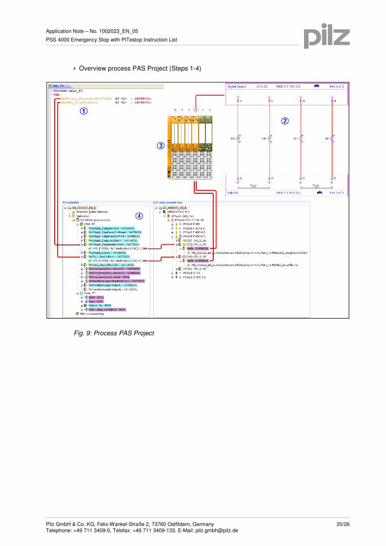
� Overview process PAS Project (Steps 1-4)
Fig. 9: Process PAS Project


14 pt
28 pt
42 pt
56 pt
70 pt
84 pt
98 pt
112 pt
126 pt
140 pt
154 pt
168 pt
182 pt
196 pt
210 pt
224 pt
238 pt
252 pt
266 pt
280 pt
294 pt
308 pt
322 pt
336 pt
350 pt
364 pt
378 pt
392 pt
406 pt
420 pt
434 pt
448 pt
462 pt
476 pt
490 pt
504 pt
518 pt
532 pt
546 pt
560 pt
574 pt
588 pt
602 pt
616 pt
630 pt
644 pt
658 pt
672 pt
686 pt
700 pt
714 pt
728 pt
742 pt
756 pt
770 pt
784 pt
798 pt
812 pt
826 pt
Application Note – No. 1002023_EN_05
PSS 4000 Emergency Stop with PITestop Instruction List
Pilz GmbH & Co. KG, Felix-Wankel-Straße 2, 73760 Ostfildern, Germany 25/26 Telephone: +49 711 3409-0, Telefax: +49 711 3409-133, E-Mail: [email protected]
4. Table of figures
Fig. 1: Hardware configuration ...................................................................................................... 7
Fig. 2: Add library element .......................................................................................................... 14
Fig. 3: Selection library element .................................................................................................. 14
Fig. 4: Mapping Editor – IL-program ........................................................................................... 17
Fig. 5: PI variables ...................................................................................................................... 18
Fig. 6: Circuit diagram (extract) ................................................................................................... 18
Fig. 7: PSSu Module Editor ......................................................................................................... 19
Fig. 8: I/O Mapping Editor ........................................................................................................... 19
Fig. 9: Process PAS Project ........................................................................................................ 20
Recommended printer settings
Adobe Acrobat Reader ( www.adobe.com )
PDF-XChange Viewer ( www.tracker-software.com )

14 pt
28 pt
42 pt
56 pt
70 pt
84 pt
98 pt
112 pt
126 pt
140 pt
154 pt
168 pt
182 pt
196 pt
210 pt
224 pt
238 pt
252 pt
266 pt
280 pt
294 pt
308 pt
322 pt
336 pt
350 pt
364 pt
378 pt
392 pt
406 pt
420 pt
434 pt
448 pt
462 pt
476 pt
490 pt
504 pt
518 pt
532 pt
546 pt
560 pt
574 pt
588 pt
602 pt
616 pt
630 pt
644 pt
658 pt
672 pt
686 pt
700 pt
714 pt
728 pt
742 pt
756 pt
770 pt
784 pt
798 pt
812 pt
826 pt
Application Note – No. 1002023_EN_05
PSS 4000 Emergency Stop with PITestop Instruction List
Pilz GmbH & Co. KG, Felix-Wankel-Straße 2, 73760 Ostfildern, Germany 26/26 Telephone: +49 711 3409-0, Telefax: +49 711 3409-133, E-Mail: [email protected]