protection of power electronics devices and circuits
TRANSCRIPT


Eng.. Usman Rehman Eng… M Zeeshan
Group Members

Protection of Devices and Circuits
Snubber circuit
CUK Regulator

Cuk regulator provide negative output voltage .
It is also a inverting regulator. The output voltage can be less then or
greater then the output voltage. In Buck boost converter, energy transfer is
associated with the inductor, whereas, in Cuk converter, energy transfer is associated with the capacitor.
In a cuk regulator the input current is continuous.
Cuk Regulator

Cuk Regulator

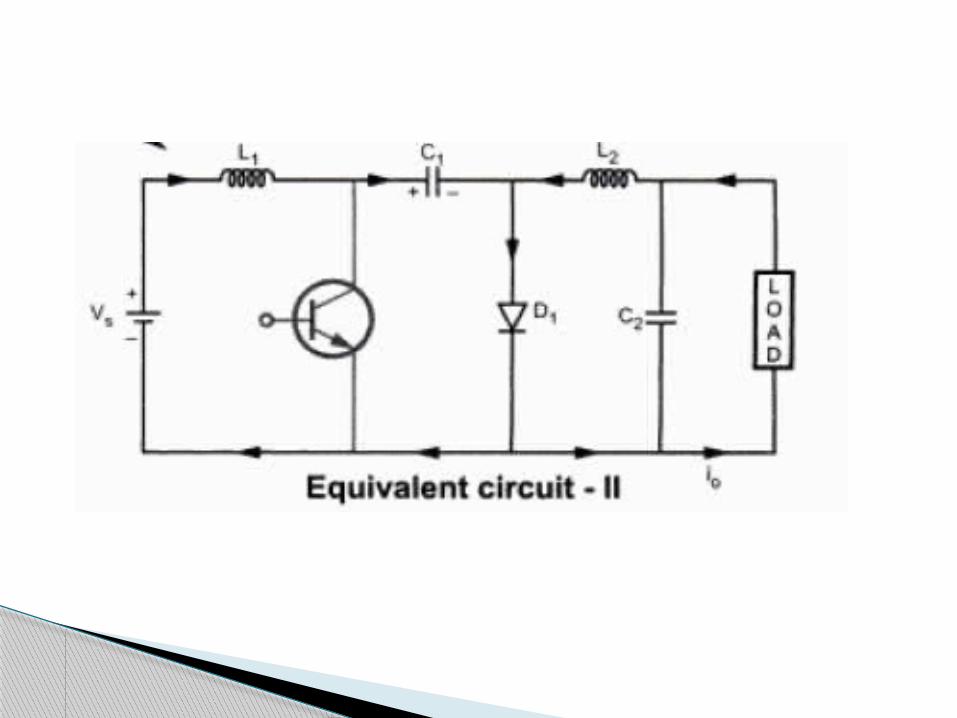
Two modes of circuit operation. Mode 1 Transistor is on at t 0. It conducts from 0 to KT. L1 store the energy from supply. Current through L1 increases. Capacitor C1 discharge its energy to the circuit
formed by C1,C2 ,load,L2.

Mode 2 When transistor is off at t 1. T1 is off at KT. The capacitor C1 charge from the input supply. Energy stored in L2 is transferred to the load. The capacitor C1 is the medium for the
transferring energy from source to load. The load current flows to L 2 and D1. The capacitor C2 also provides load current and
tries to maintain the load voltage.

Graph
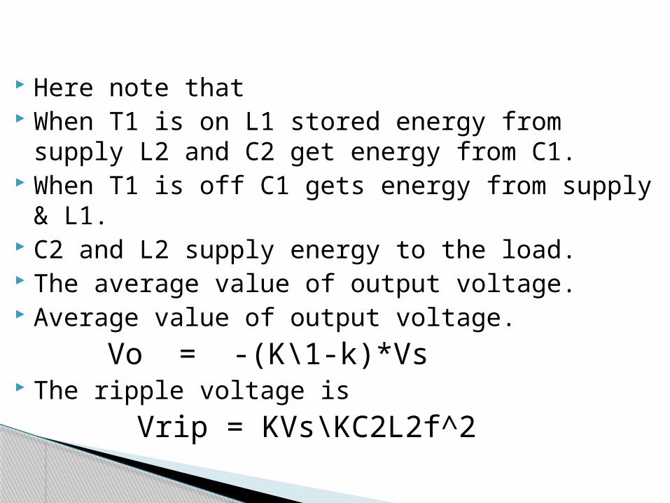
Here note that When T1 is on L1 stored energy from supply L2
and C2 get energy from C1. When T1 is off C1 gets energy from supply & L1. C2 and L2 supply energy to the load. The average value of output voltage. Average value of output voltage.
Vo = -(K\1-k)*Vs The ripple voltage is
Vrip = KVs\KC2L2f^2

Introduction Even in carefully design circuits, short circuits fault
conditions may exist. Resulting in an excessive current flow through the
devices. The reliable operation of converter would required
ensuring that all time the circuit condition do not exceed the rating of the power devices by providing protection against
Over voltage Over current Over heating
Protection of Devices and Circuits

In the power devices are protected from.. Thermal runaway by heat sinks High voltage and current by snubbers Reverse recovery transient Supply and load-side transients Fault condition by fuses
Continue…

A heat sink transfers thermal energy from a higher temperature device to a lower temperature fluid medium.
The fluid medium is frequently air, but can also be water, refrigerants or oil.
Practical heat sinks for electronic devices must have a temperature higher than the surroundings to transfer heat by convection radiation, and conduction
Different types of heat sink: Extruded heat sinks Stamped heat sinks Bonded fin heat sinks
Cooling and heat sinks
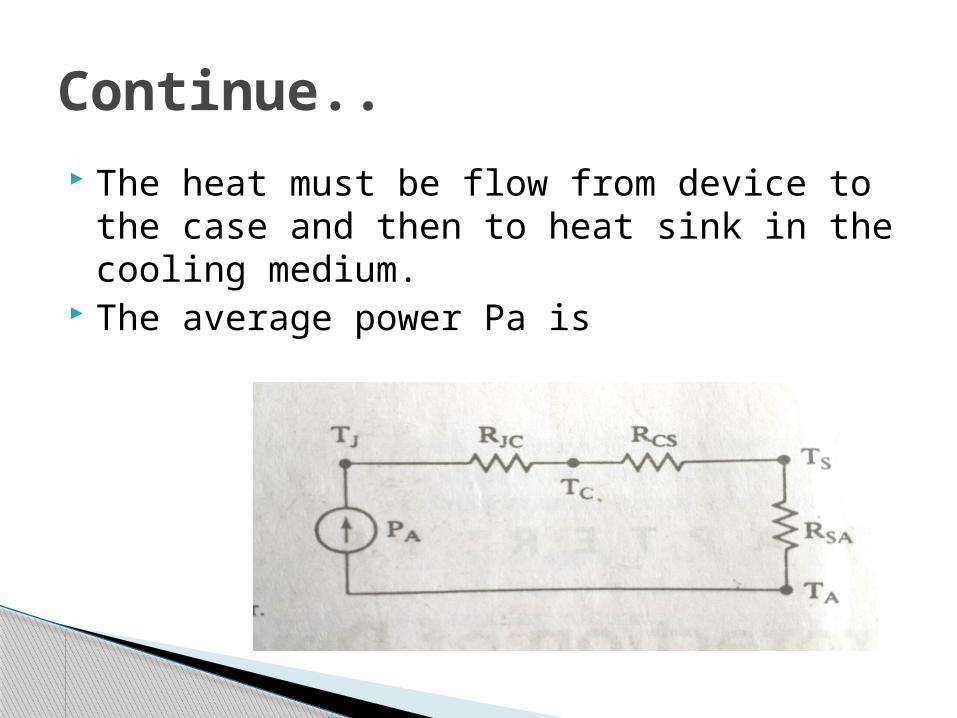
The heat must be flow from device to the case and then to heat sink in the cooling medium.
The average power Pa is
Continue..
Tj = Pa(Rjc + Rcs + Rsa) Where Rjc = Thermal resistance from junction to
case. Rcs = Thermal resistance from case to sink. Rsa = thermal resistance from sink to ambient. Ta = ambient temperature
The required thermal resistance of the heat sink can be calculated for a known ambient temperature.
Continue..


To understand the principle of a heat sink, consider Fourier's law of heat conduction. Fourier's law of heat conduction, simplified to a one-dimensional form in the x-direction, shows that when there is a temperature gradient in a body, heat will be transferred from the higher temperature region to the lower temperature region. The rate at which heat is transferred by conduction ,qk , is proportional to the product of the temperature gradient and the cross-sectional area through which heat is transferred.
Heat transfer principle
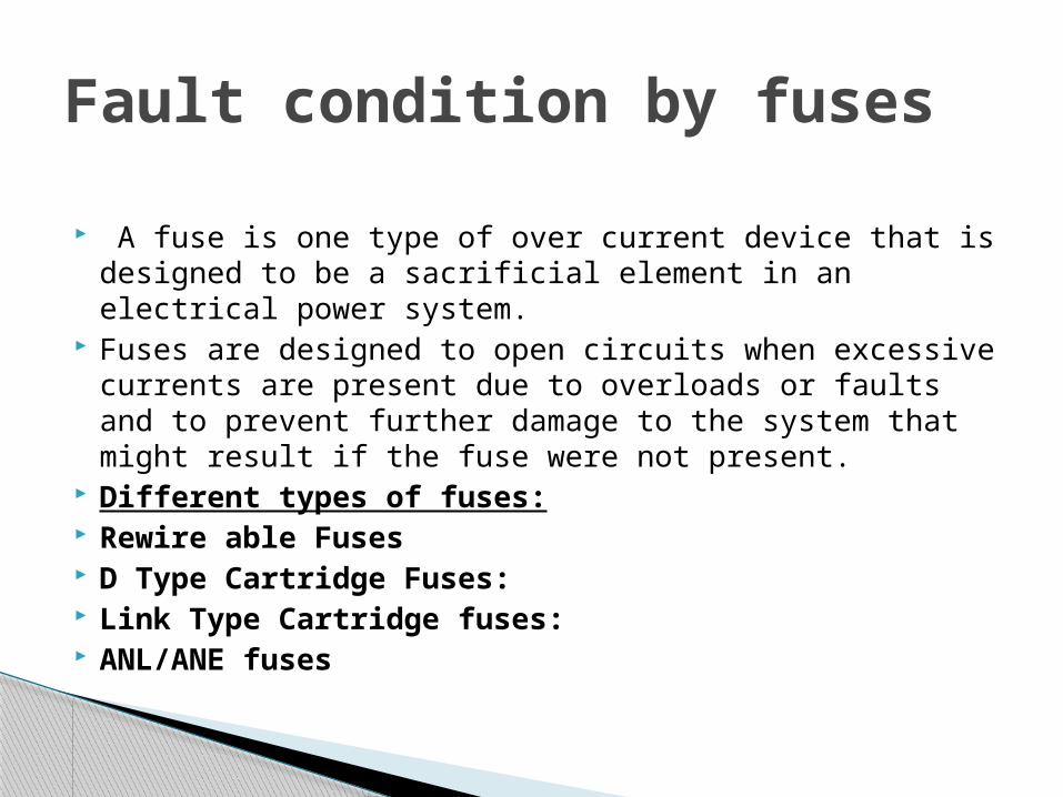
A fuse is one type of over current device that is designed to be a sacrificial element in an electrical power system.
Fuses are designed to open circuits when excessive currents are present due to overloads or faults and to prevent further damage to the system that might result if the fuse were not present.
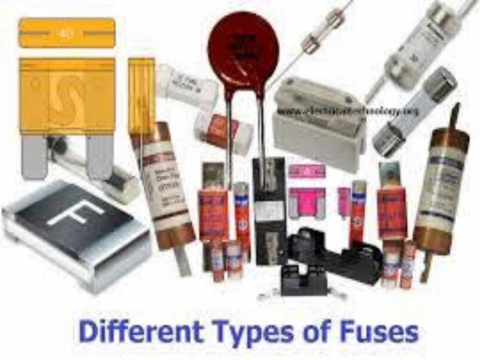
Different types of fuses: Rewire able Fuses D Type Cartridge Fuses: Link Type Cartridge fuses: ANL/ANE fuses
Fault condition by fuses
In selecting a fuse it is necessary to estimate the fault current and then satisfy the following requirements:
The fuse must carry continuously the devise rated current.
The I^2 t let-through value of the fuse before the fault current is cleared must be less then rated I^2t of the device to be protected.
The fuse must be able to with stand the voltage, after the arc extinction.
The peak arc voltage must be less then the peak voltage rating of the device.
Continue…

The use of metallic conductors in series in the circuit as a melt, when the overload or short circuit current through the melt, because of its self heating and fuse, thus breaking an electrical circuit.
Fuse structure is simple, easy to use, widely used in power systems, a variety of electrical equipment and appliances as a protection device.
When the fault current raises the fuse temperature also rises until T=Tm at which times fuse melt and arcs are developed across the fuse.
The clearing time Tc is the sum of melting time Tm and the arc time Ta.
Working principle
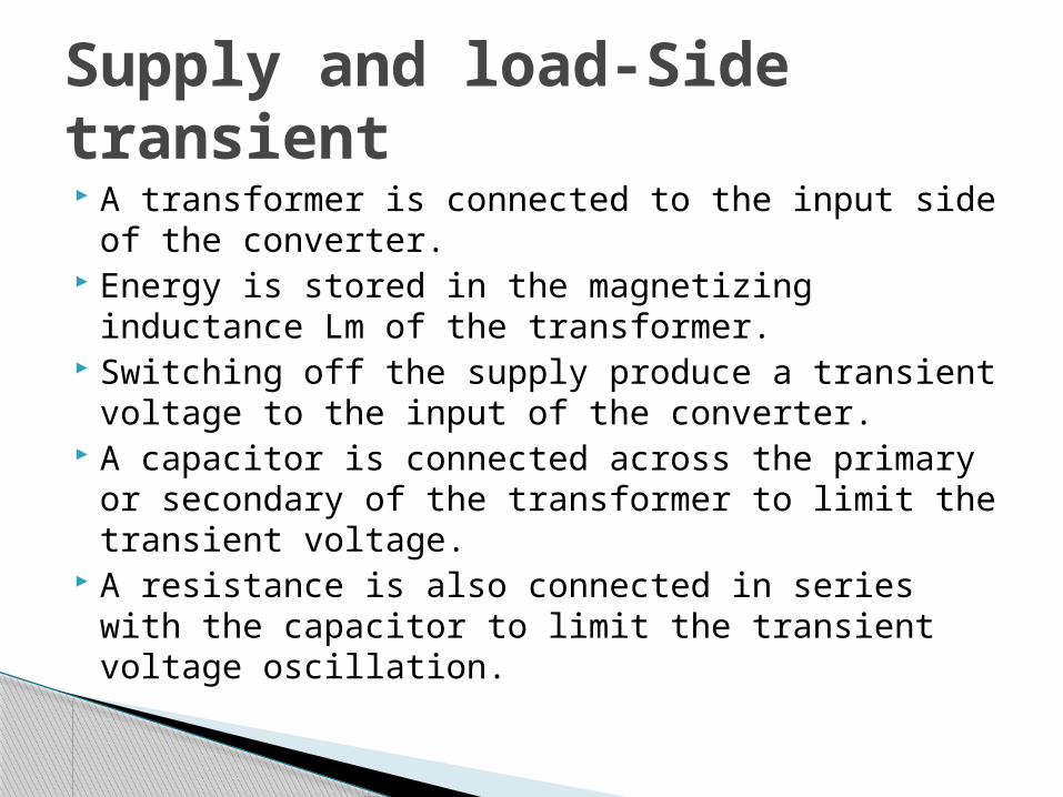
A transformer is connected to the input side of the converter.
Energy is stored in the magnetizing inductance Lm of the transformer.
Switching off the supply produce a transient voltage to the input of the converter.
A capacitor is connected across the primary or secondary of the transformer to limit the transient voltage.
A resistance is also connected in series with the capacitor to limit the transient voltage oscillation.
Supply and load-Side transient

Under the steady state condition Vs=Vmsinwt and the magnetizing current is given by
Lm di\dt=VmsinwtWhich gives
I(t) = - Vm/wLm coswt
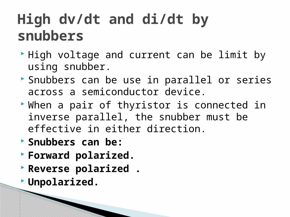
High voltage and current can be limit by using snubber.
Snubbers can be use in parallel or series across a semiconductor device.
When a pair of thyristor is connected in inverse parallel, the snubber must be effective in either direction.
Snubbers can be: Forward polarized. Reverse polarized . Unpolarized.
High dv/dt and di/dt by snubbers

snubber is a device used to suppress ("snub") some phenomenon, such as:
Voltage transients in electrical systems. Pressure transients in fluid systems. Excess force or rapid movement
in mechanical systems.
Snubber circuit

A simple snubber uses a small resistor (R) in series with a small capacitor (C).
This combination can be used to suppress the rapid rise in voltage across a thyristor, preventing the erroneous turn-on of the thyristor; it does this by limiting the rate of rise in voltage (dV/dt) across the thyristor to a value which will not trigger it.
An appropriately-designed RC snubber can be used with either DC or AC loads. This sort of snubber is commonly used with inductive loads such as electric motors.
RC Snubbers

An RC snubber is normally connected across a semiconductor device to limit the dv/dt within the maximum allowable rating.
RC snubbers can be made discretely and are also built as a single component.
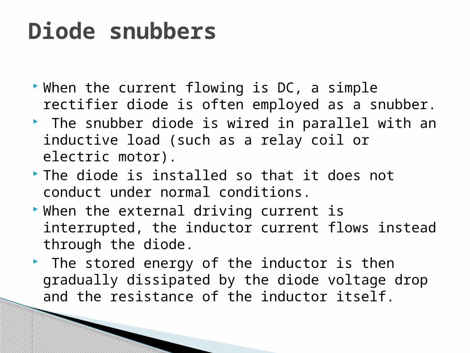
When the current flowing is DC, a simple rectifier diode is often employed as a snubber.
The snubber diode is wired in parallel with an inductive load (such as a relay coil or electric motor).
The diode is installed so that it does not conduct under normal conditions.
When the external driving current is interrupted, the inductor current flows instead through the diode.
The stored energy of the inductor is then gradually dissipated by the diode voltage drop and the resistance of the inductor itself.
Diode snubbers
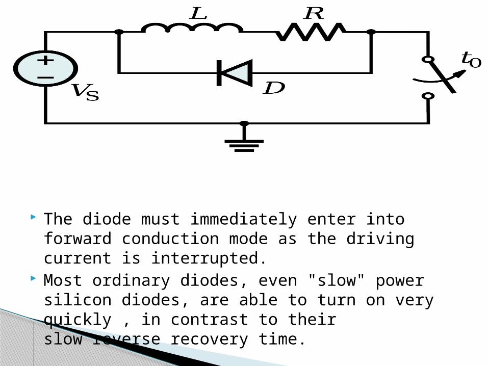
The diode must immediately enter into forward conduction mode as the driving current is interrupted.
Most ordinary diodes, even "slow" power silicon diodes, are able to turn on very quickly , in contrast to their slow reverse recovery time.

