power electronics epe 550 circuits, devices, and applications electrical drives:
DESCRIPTION
POWER ELECTRONICS EPE 550 CIRCUITS, DEVICES, AND APPLICATIONS ELECTRICAL DRIVES: An Application of Power Electronics. Eng.Mohammed Alsumady. CONTENTS. Power Electronic Systems. Modern Electrical Drive Systems. Power Electronic Converters in Electrical Drives. :: DC and AC Drives. - PowerPoint PPT PresentationTRANSCRIPT
POWER ELECTRONICSPOWER ELECTRONICSEPE 550
CIRCUITS, DEVICES, AND APPLICATIONS
ELECTRICAL DRIVES: ELECTRICAL DRIVES: An Application of Power Electronics
Eng.Mohammed AlsumadyEng.Mohammed Alsumady
CONTENTSCONTENTS
Power Electronic SystemsPower Electronic Systems
Modern Electrical Drive Systems Modern Electrical Drive Systems
Power Electronic Converters in Electrical DrivesPower Electronic Converters in Electrical Drives
:: DC and AC Drives:: DC and AC Drives
Modeling and Control of Electrical Modeling and Control of Electrical DrivesDrives:: Current controlled Converters:: Current controlled Converters
:: Modeling of Power Converters:: Modeling of Power Converters :: Scalar control of IM:: Scalar control of IM
Power Electronic SystemsPower Electronic Systems
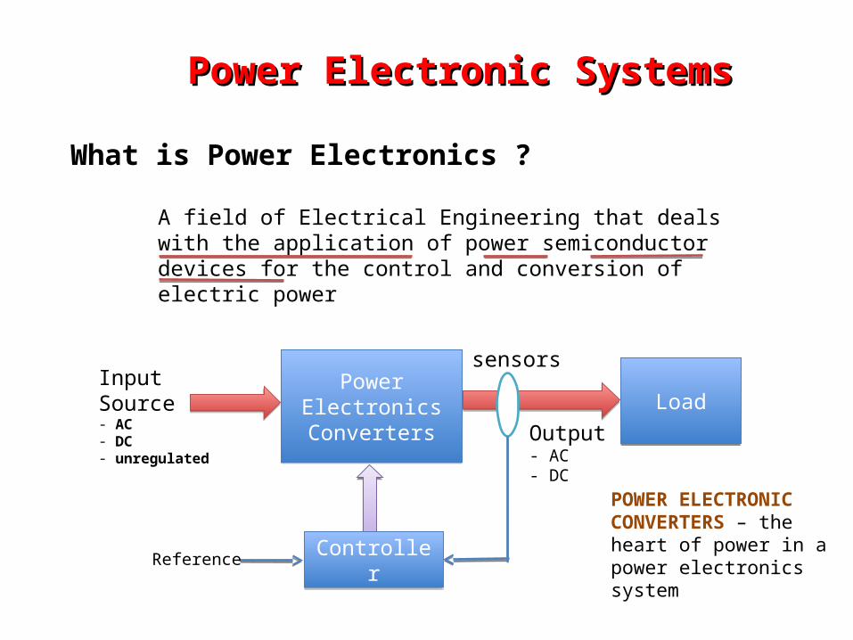
What is Power Electronics ?
A field of Electrical Engineering that deals with the application of power semiconductor devices for the control and conversion of electric power
Power ElectronicsConverters
Power ElectronicsConverters
LoadLoad
ControllerController
Output- AC- DC
InputSource- AC- DC- unregulated
Reference
POWER ELECTRONIC CONVERTERS – the heart of power in a power electronics system
sensors
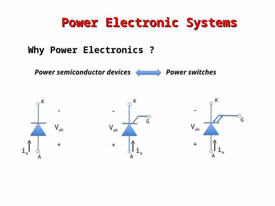
Power Electronic SystemsPower Electronic Systems
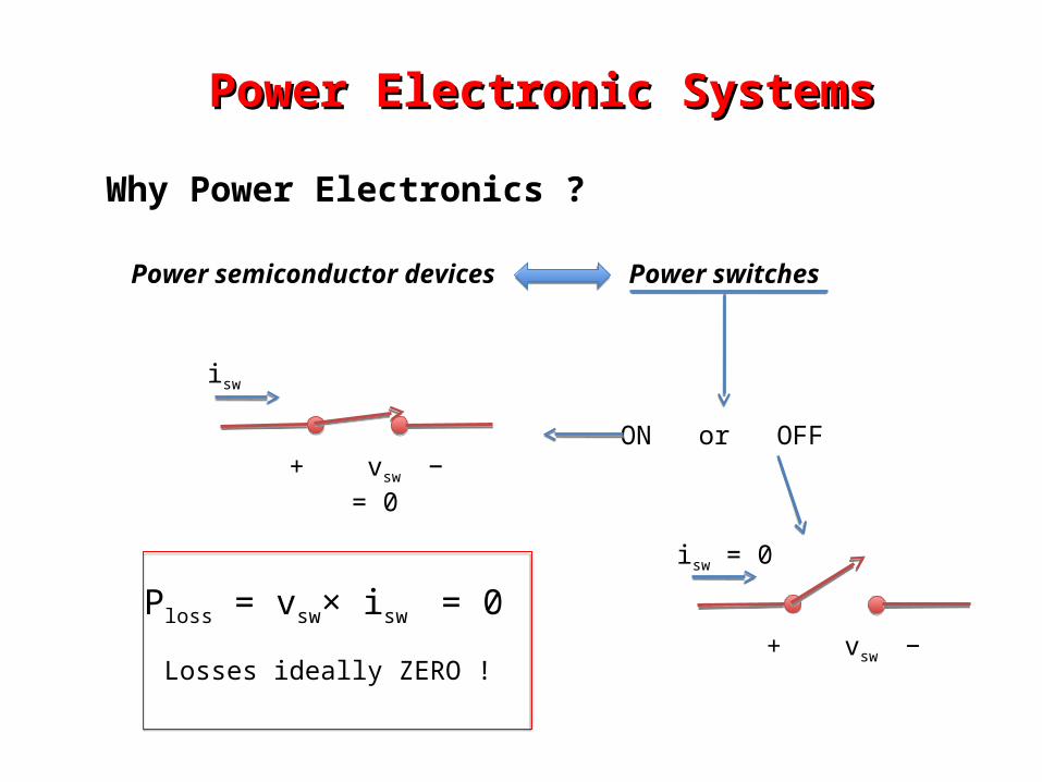
Why Power Electronics ?
Power semiconductor devices Power switches
ON or OFF+ vsw − = 0
isw
+ vsw −
isw = 0
Ploss = vsw× isw = 0
Losses ideally ZERO !
Power Electronic SystemsPower Electronic Systems
Why Power Electronics ?
Power semiconductor devices Power switches
Vak
+ia
G
K
A
Vak
+ia
K
A
Vak
+ia
G
K
A
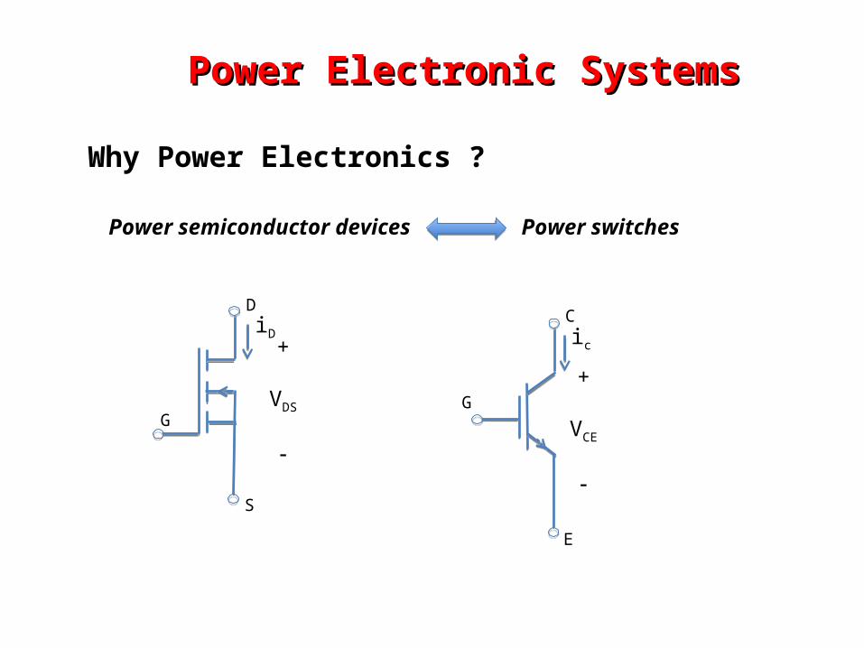
Power Electronic SystemsPower Electronic Systems
Why Power Electronics ?
Power semiconductor devices Power switches
D
S
G
+
VDS
iD
G
C
E
+
VCE
ic
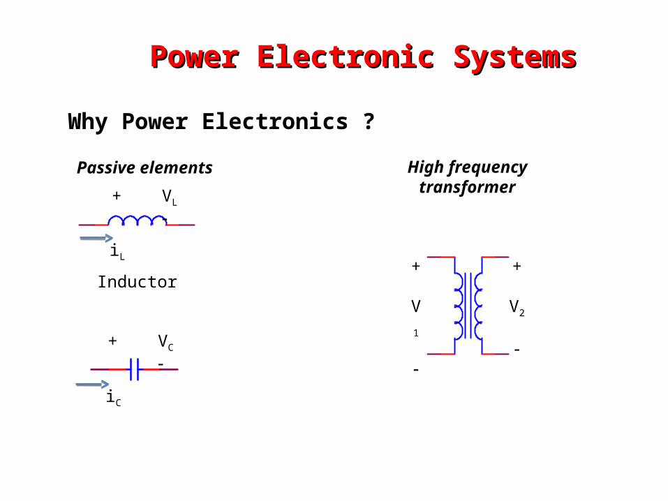
Power Electronic SystemsPower Electronic Systems
Why Power Electronics ?
Passive elements High frequencytransformer
+
V1
+
V2
Inductor
+ VL
iL
+ VC
iC
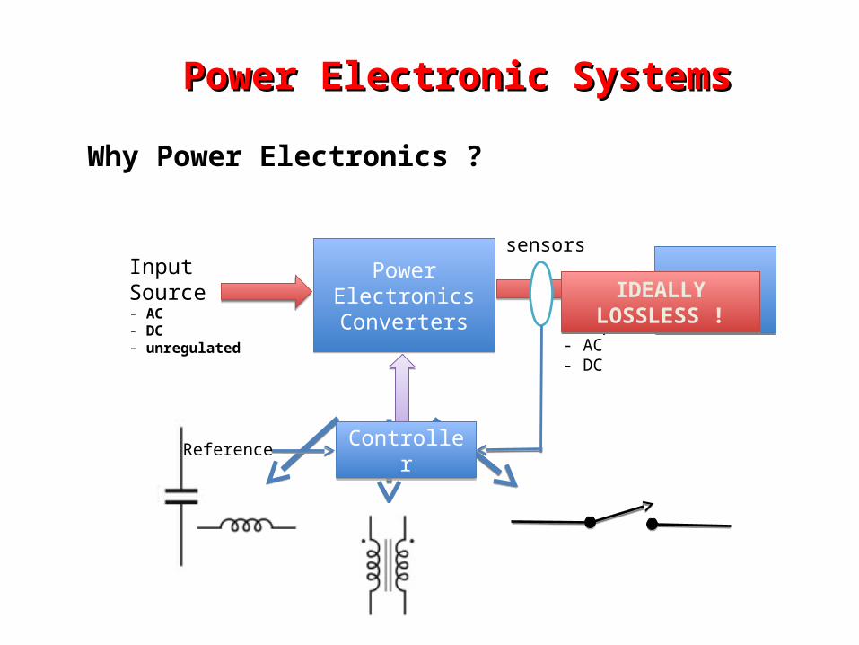
Power Electronic SystemsPower Electronic Systems
Why Power Electronics ?
Power ElectronicsConverters
Power ElectronicsConverters
sensors
LoadLoad
ControllerController
Output- AC- DC
InputSource- AC- DC- unregulated
Reference
IDEALLY LOSSLESS !IDEALLY LOSSLESS !
Power Electronic SystemsPower Electronic Systems
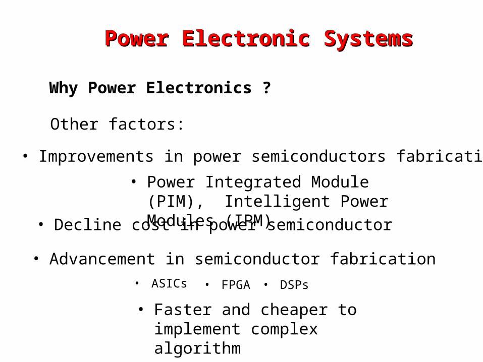
Why Power Electronics ?
Other factors:
• Improvements in power semiconductors fabrication
• Decline cost in power semiconductor
• Advancement in semiconductor fabrication
• ASICs • FPGA • DSPs
• Faster and cheaper to implement complex algorithm
• Power Integrated Module (PIM), Intelligent Power Modules (IPM)
Advancement in semiconductor fabrication• A field-programmable gate array (FPGA) is an integrated circuit designed to be configured by the
customer or designer after manufacturing—hence "field-programmable". The FPGA configuration is generally specified using a hardware description language (HDL), similar to that used for an application-specific integrated circuit (ASIC) circuit diagrams were previously used to specify the configuration, as they were for ASICs, but this is increasingly rare). FPGAs can be used to implement any logical function that an ASIC could perform. The ability to update the functionality after shipping, partial re-configuration of the portion of the design and the low non-recurring engineering costs relative to an ASIC design (notwithstanding the generally higher unit cost), offer advantages for many applications.
• FPGAs contain programmable logic components called "logic blocks", and a hierarchy of reconfigurable interconnects that allow the blocks to be "wired together"—somewhat like many (changeable) logic gates that can be inter-wired in (many) different configurations. Logic blocks can be configured to perform complex combinational functions, or merely simple logic gates like AND and XOR. In most FPGAs, the logic blocks also include memory elements, which may be simple flip-flops or more complete blocks of memory.
• In addition to digital functions, some FPGAs have analog features. The most common analog feature is programmable slew rate and drive strength on each output pin, allowing the engineer to set slow rates on lightly loaded pins that would otherwise ring unacceptably, and to set stronger, faster rates on heavily loaded pins on high-speed channels that would otherwise run too slow. Another relatively common analog feature is differential comparators on input pins designed to be connected to differential signaling channels.
A field-programmable gate array (FPGA)
• The FPGA industry sprouted from programmable read-only memory (PROM) and programmable logic devices (PLDs). PROMs and PLDs both had the option of being programmed in batches in a factory or in the field (field programmable), however programmable logic was hard-wired between logic gates.
• A recent trend has been to take the coarse-grained architectural approach a step further by combining the logic blocks and interconnects of traditional FPGAs with embedded microprocessors and related peripherals to form a complete "system on a programmable chip“.
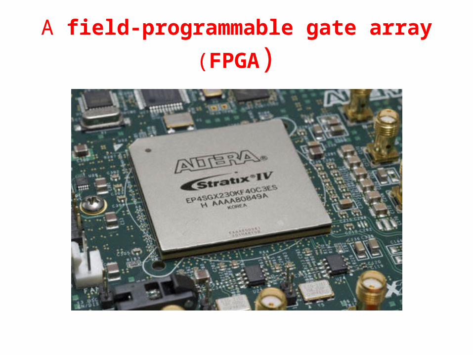
A field-programmable gate array (FPGA)
Power Electronic SystemsPower Electronic Systems
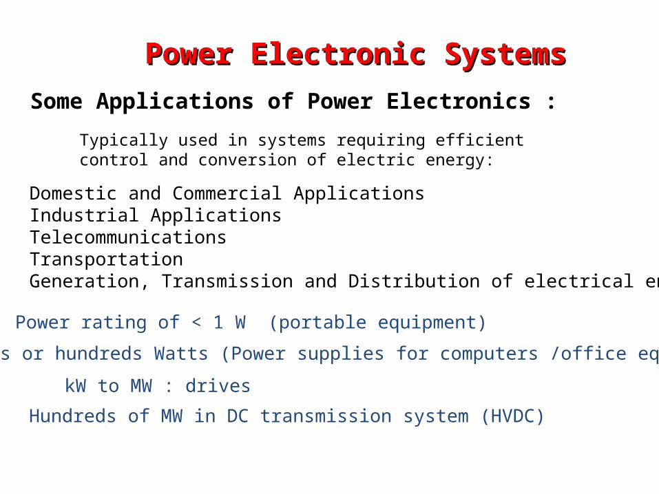
Some Applications of Power Electronics :
Power rating of < 1 W (portable equipment)
Tens or hundreds Watts (Power supplies for computers /office equipment)
Typically used in systems requiring efficient control and conversion of electric energy:
Domestic and Commercial ApplicationsIndustrial ApplicationsTelecommunicationsTransportationGeneration, Transmission and Distribution of electrical energy
kW to MW : drives
Hundreds of MW in DC transmission system (HVDC)
Modern Electrical Drive SystemsModern Electrical Drive Systems
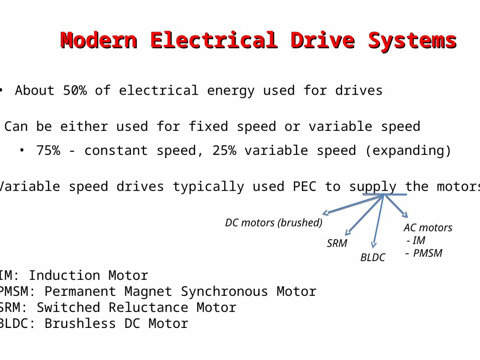
• About 50% of electrical energy used for drives
• Can be either used for fixed speed or variable speed
• 75% - constant speed, 25% variable speed (expanding)
• Variable speed drives typically used PEC to supply the motors
• IM: Induction Motor• PMSM: Permanent Magnet Synchronous Motor• SRM: Switched Reluctance Motor• BLDC: Brushless DC Motor
AC motors - IM- PMSM
DC motors (brushed)
SRMBLDC
Permanent Magnet Synchronous MotorPermanent Magnet Synchronous Motor The Permanent Magnet Synchronous motor is a rotating electric machine
where the stator is a classic three phase stator like that of an induction motor and the rotor has permanent magnets. In this respect, the PM Synchronous motor is equivalent to an induction motor, except the rotor magnetic field in case of PMSM is produced by permanent magnets. The use of a permanent magnet to generate a substantial air gap magnetic flux makes it possible to design highly efficient PM motors. Medium construction complexity, multiple fields, delicate magnets
• High reliability (no brush wear), even at very high achievable speeds
• High efficiency
• Low EMI
• Driven by multi-phase Inverter controllers
• Sensorless speed control possible
• Higher total system cost than for DC motors
• Smooth rotation - without torque ripple
• Appropriate for position control
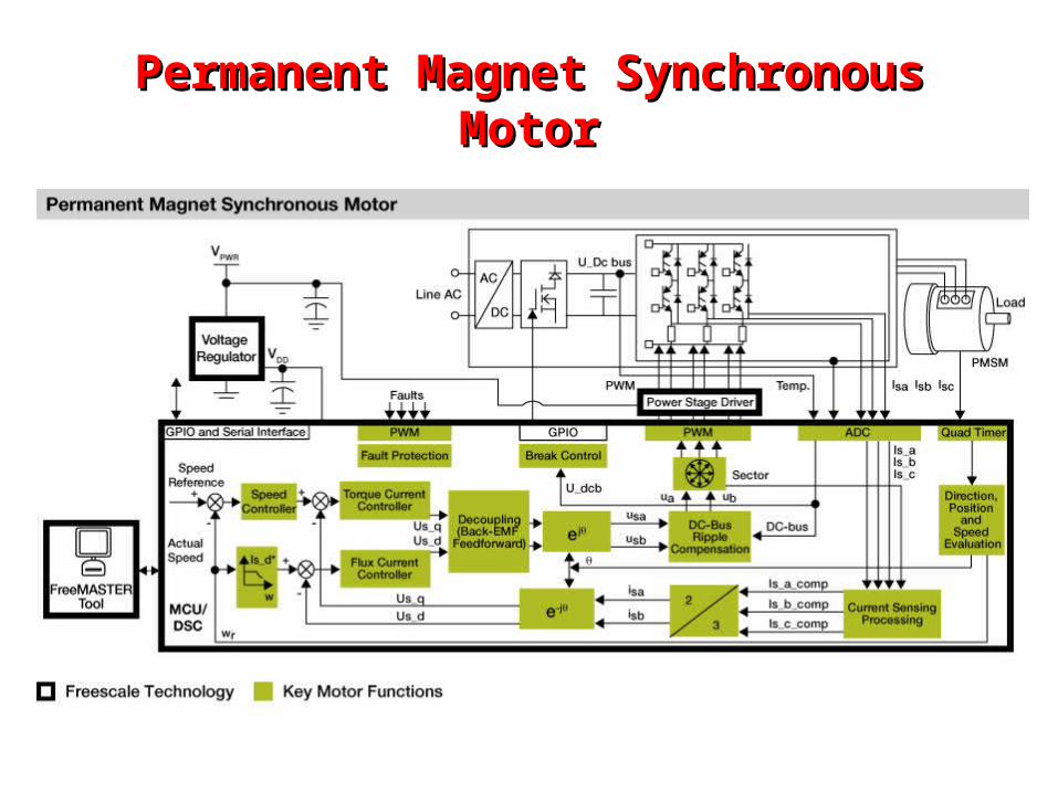
Permanent Magnet Synchronous MotorPermanent Magnet Synchronous Motor
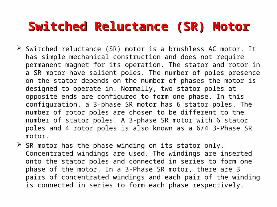
Switched Reluctance (SR) MotorSwitched Reluctance (SR) Motor
Switched reluctance (SR) motor is a brushless AC motor. It has simple mechanical construction and does not require permanent magnet for its operation. The stator and rotor in a SR motor have salient poles. The number of poles presence on the stator depends on the number of phases the motor is designed to operate in. Normally, two stator poles at opposite ends are configured to form one phase. In this configuration, a 3-phase SR motor has 6 stator poles. The number of rotor poles are chosen to be different to the number of stator poles. A 3-phase SR motor with 6 stator poles and 4 rotor poles is also known as a 6/4 3-Phase SR motor.
SR motor has the phase winding on its stator only. Concentrated windings are used. The windings are inserted onto the stator poles and connected in series to form one phase of the motor. In a 3-Phase SR motor, there are 3 pairs of concentrated windings and each pair of the winding is connected in series to form each phase respectively.
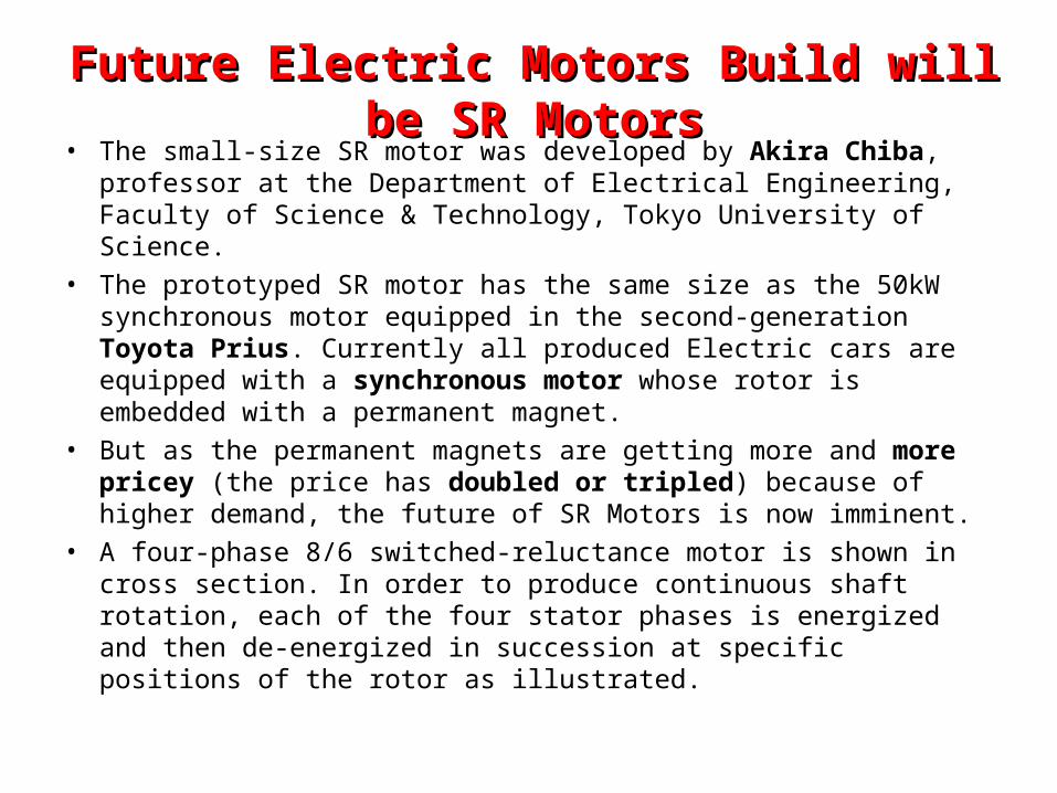
Future Electric Motors Build will be SR MotorsFuture Electric Motors Build will be SR Motors• The small-size SR motor was developed by Akira Chiba, professor at the
Department of Electrical Engineering, Faculty of Science & Technology, Tokyo University of Science.
• The prototyped SR motor has the same size as the 50kW synchronous motor equipped in the second-generation Toyota Prius. Currently all produced Electric cars are equipped with a synchronous motor whose rotor is embedded with a permanent magnet.
• But as the permanent magnets are getting more and more pricey (the price has doubled or tripled) because of higher demand, the future of SR Motors is now imminent.
• A four-phase 8/6 switched-reluctance motor is shown in cross section. In order to produce continuous shaft rotation, each of the four stator phases is energized and then de-energized in succession at specific positions of the rotor as illustrated.
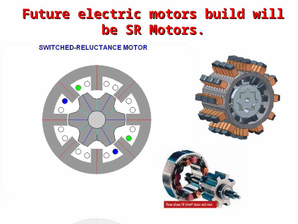
Future electric motors build will be SR Motors.Future electric motors build will be SR Motors.
Brushless DC MotorBrushless DC Motor
• A BLDC motor has permanent magnets which rotate, and a fixed armature, eliminating the problems of connecting current to the moving armature. An electronic controller replaces the brush commutator assembly of the brushed DC motor, which continually switches the phase to the windings to keep the motor turning. The controller performs similar timed power distribution by using a solid-state circuit rather than the brush commutator system.
• BLDC motors offer several advantages over brushed DC motors, including more torque per weight, more torque per watt (increased efficiency), increased reliability, reduced noise, longer lifetime (no brush and commutator erosion), elimination of ionizing sparks from the commutator, and overall reduction of electromagnetic interference (EMI). With no windings on the rotor, they are not subjected to centrifugal forces, and because the windings are supported by the housing, they can be cooled by conduction, requiring no airflow inside the motor for cooling. This in turn means that the motor's internals can be entirely enclosed and protected from dirt or other foreign matter.
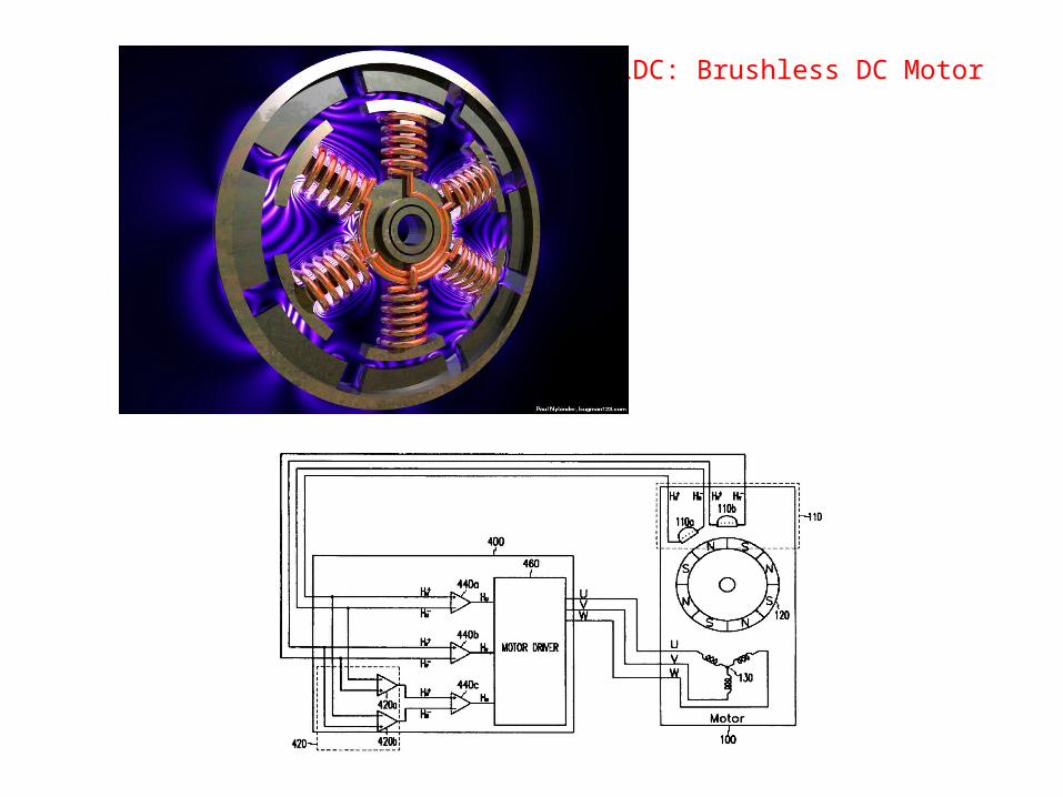
BLDC: Brushless DC Motor
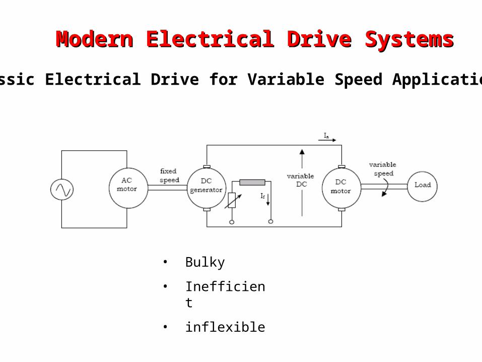
Modern Electrical Drive SystemsModern Electrical Drive Systems
Classic Electrical Drive for Variable Speed Application :
• Bulky
• Inefficient
• inflexible
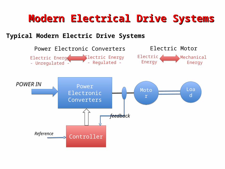
Modern Electrical Drive SystemsModern Electrical Drive Systems
PowerElectronicConverters
PowerElectronicConverters
LoadLoadMotor
Motor
ControllerControllerReference
POWER IN
feedback
Typical Modern Electric Drive Systems
Power Electronic Converters
Electric Energy- Unregulated -
Electric Energy- Regulated -
Electric MotorElectric Energy
Mechanical Energy
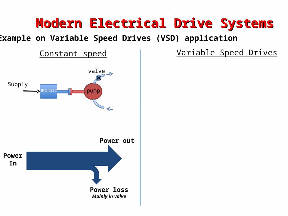
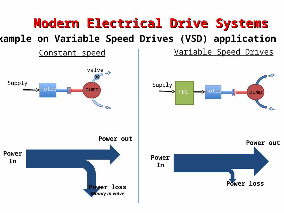
Modern Electrical Drive SystemsModern Electrical Drive SystemsExample on Variable Speed Drives (VSD) application
motor pump
valve
Supply
Constant speed Variable Speed Drives
PowerIn
Power lossMainly in valve
Power out
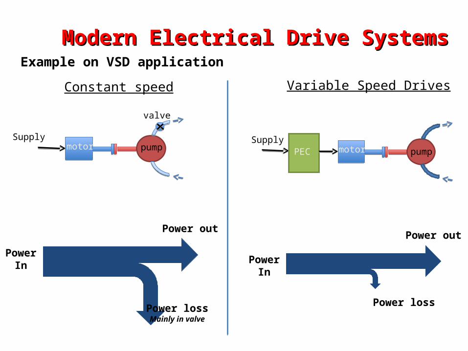
Modern Electrical Drive SystemsModern Electrical Drive SystemsExample on Variable Speed Drives (VSD) application
PowerIn
Power lossMainly in valve
Power out
motor pump
valve
SupplymotorPEC pump
Supply
Constant speed Variable Speed Drives
PowerIn
Power loss
Power out
Modern Electrical Drive SystemsModern Electrical Drive Systems
PowerIn
Power lossMainly in valve
Power out
PowerIn
Power loss
Power out
motor pump
valve
SupplymotorPEC pump
Supply
Constant speed Variable Speed Drives
Example on VSD application
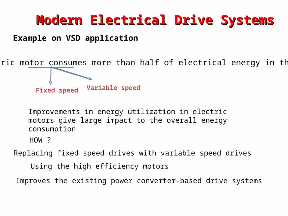
Modern Electrical Drive SystemsModern Electrical Drive Systems
Electric motor consumes more than half of electrical energy in the US
Fixed speed Variable speed
HOW ?
Improvements in energy utilization in electric motors give large impact to the overall energy consumption
Replacing fixed speed drives with variable speed drives
Using the high efficiency motors
Improves the existing power converter–based drive systems
Example on VSD application
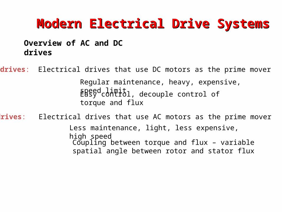
DC drives: Electrical drives that use DC motors as the prime mover
Regular maintenance, heavy, expensive, speed limit
AC drives: Electrical drives that use AC motors as the prime mover
Less maintenance, light, less expensive, high speed
Modern Electrical Drive SystemsModern Electrical Drive Systems
Overview of AC and DC drives
Easy control, decouple control of torque and flux
Coupling between torque and flux – variable spatial angle between rotor and stator flux
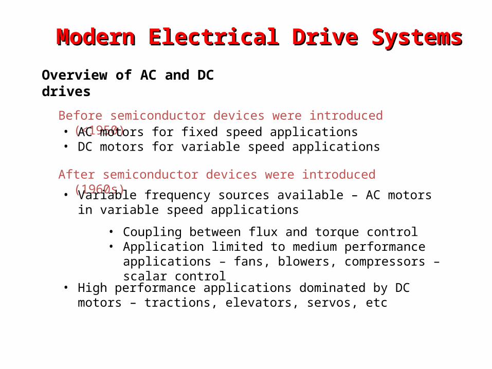
Before semiconductor devices were introduced (<1950)• AC motors for fixed speed applications• DC motors for variable speed applications
After semiconductor devices were introduced (1960s)
• Variable frequency sources available – AC motors in variable speed applications
• Coupling between flux and torque control• Application limited to medium performance applications – fans,
blowers, compressors – scalar control
• High performance applications dominated by DC motors – tractions, elevators, servos, etc
Modern Electrical Drive SystemsModern Electrical Drive Systems
Overview of AC and DC drives
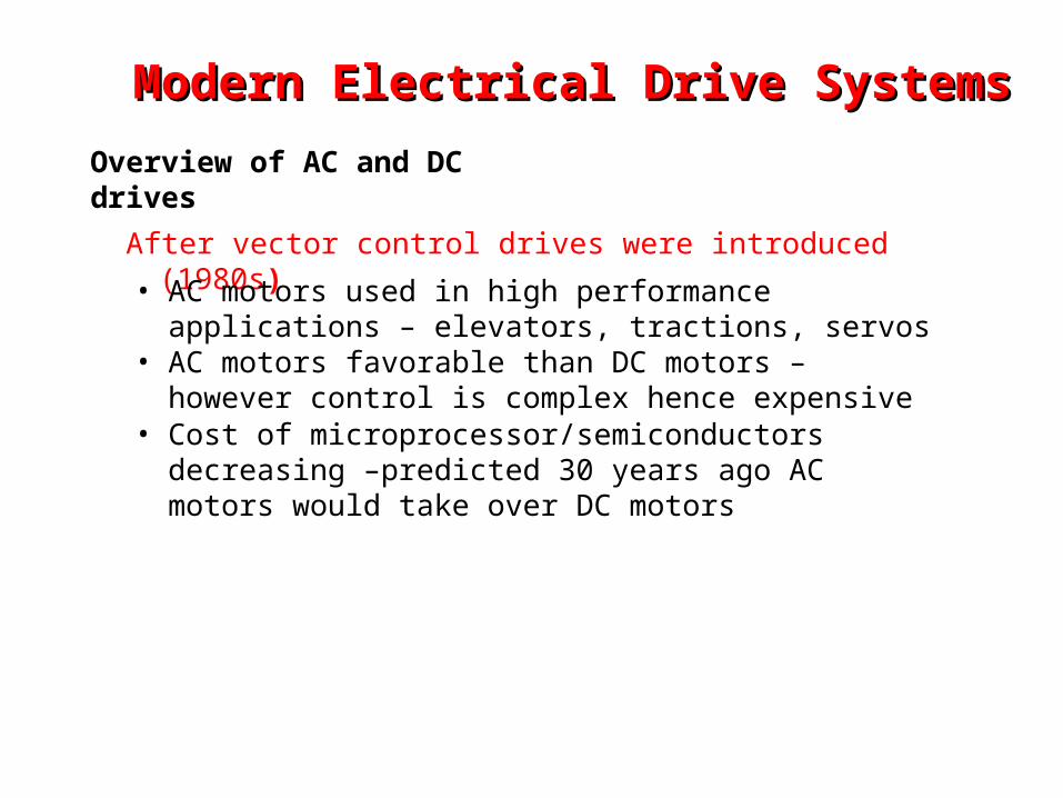
After vector control drives were introduced (1980s)
• AC motors used in high performance applications – elevators, tractions, servos
• AC motors favorable than DC motors – however control is complex hence expensive
• Cost of microprocessor/semiconductors decreasing –predicted 30 years ago AC motors would take over DC motors
Modern Electrical Drive SystemsModern Electrical Drive Systems
Overview of AC and DC drives
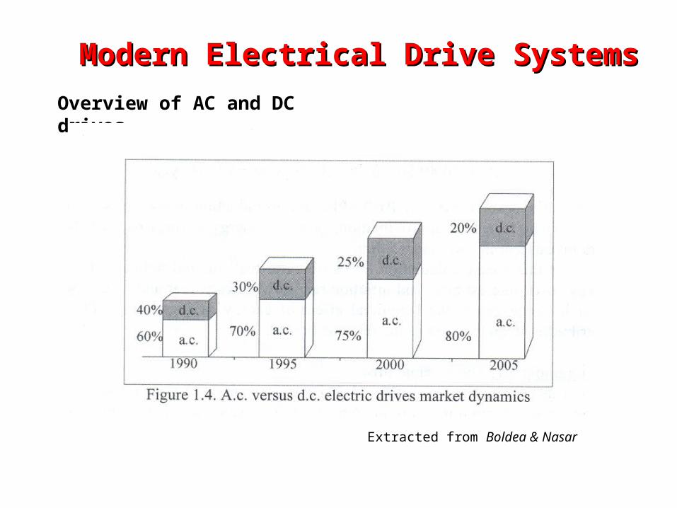
Overview of AC and DC drives
Extracted from Boldea & Nasar
Modern Electrical Drive SystemsModern Electrical Drive Systems
Power Electronic Converters in Electrical Drive SystemsPower Electronic Converters in Electrical Drive Systems
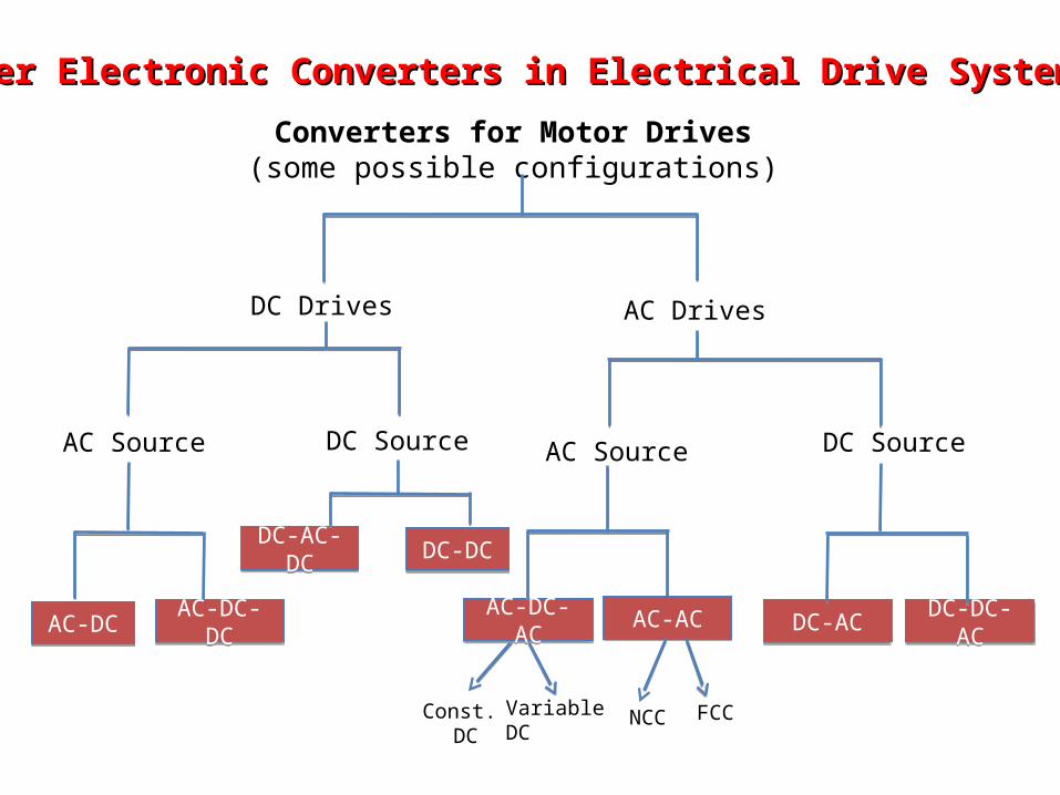
Converters for Motor Drives(some possible configurations)
DC Drives AC Drives
DC SourceAC Source
AC-DC-DCAC-DC-DCAC-DCAC-DC
AC Source
Const. DC
Variable DC
AC-DC-ACAC-DC-AC AC-ACAC-AC
NCC FCC
DC Source
DC-ACDC-AC DC-DC-ACDC-DC-AC
DC-DCDC-DCDC-AC-DCDC-AC-DC
Power Electronic Converters in ED SystemsPower Electronic Converters in ED Systems
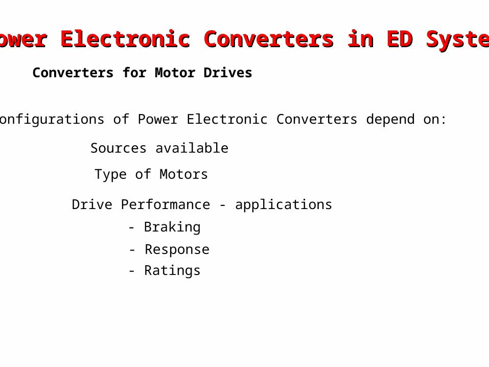
Converters for Motor Drives
Configurations of Power Electronic Converters depend on:
Sources available
Type of Motors
Drive Performance - applications
- Braking
- Response
- Ratings
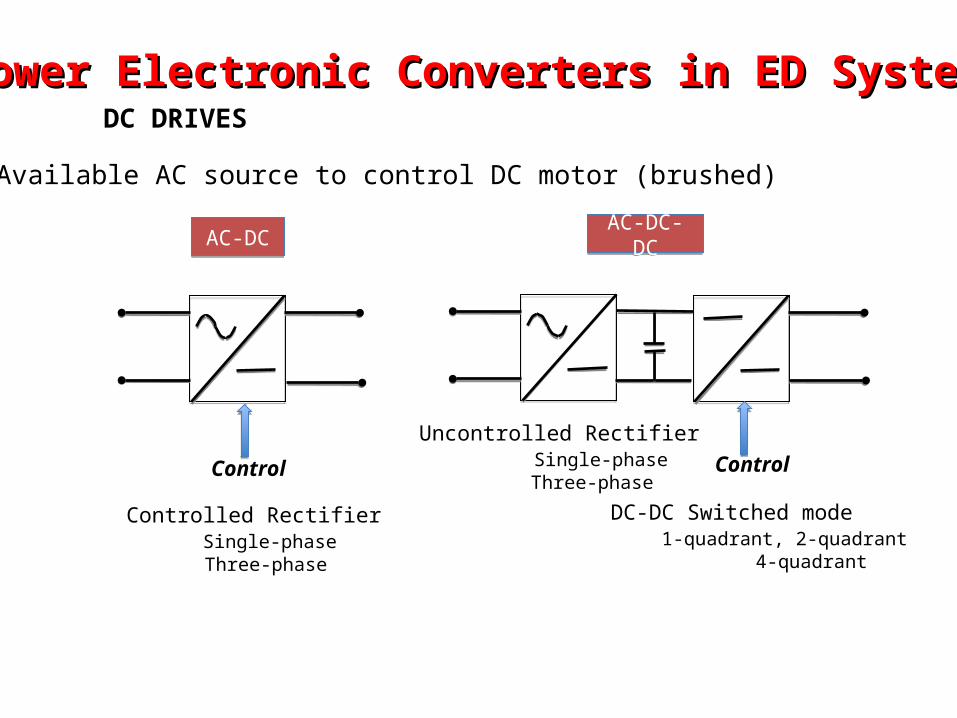
Power Electronic Converters in ED SystemsPower Electronic Converters in ED SystemsDC DRIVES
Available AC source to control DC motor (brushed)
AC-DC-DCAC-DC-DCAC-DCAC-DC
Controlled Rectifier Single-phase Three-phase
Uncontrolled Rectifier Single-phase Three-phase
DC-DC Switched mode 1-quadrant, 2-quadrant 4-quadrant
Control Control
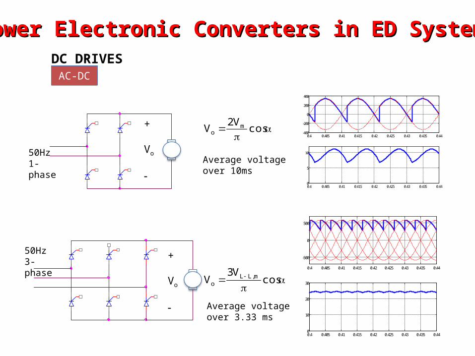
Power Electronic Converters in ED SystemsPower Electronic Converters in ED SystemsDC DRIVES
+
Vo
+
Vo
cosV2
V mo
cosV3
V m,LLo
Average voltage over 10ms
Average voltage over 3.33 ms
50Hz1-phase
50Hz3-phase
AC-DCAC-DC
0.4 0.405 0.41 0.415 0.42 0.425 0.43 0.435 0.44-400
-200
0
200
400
0.4 0.405 0.41 0.415 0.42 0.425 0.43 0.435 0.440
5
10
0.4 0.405 0.41 0.415 0.42 0.425 0.43 0.435 0.44
-500
0
500
0.4 0.405 0.41 0.415 0.42 0.425 0.43 0.435 0.440
10
20
30
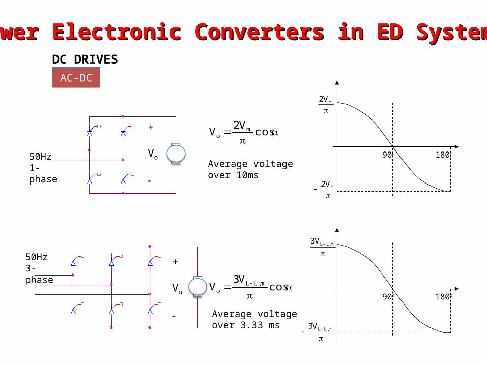
Power Electronic Converters in ED SystemsPower Electronic Converters in ED SystemsDC DRIVES
+
Vo
+
Vo
cosV2
V mo
90o 180o
mV2
mV2
90o
m,LLV3
m,LLV3
cosV3
V m,LLo
Average voltage over 10ms
Average voltage over 3.33 ms
50Hz1-phase
50Hz3-phase
180o
AC-DCAC-DC
Power Electronic Converters in ED SystemsPower Electronic Converters in ED SystemsDC DRIVES
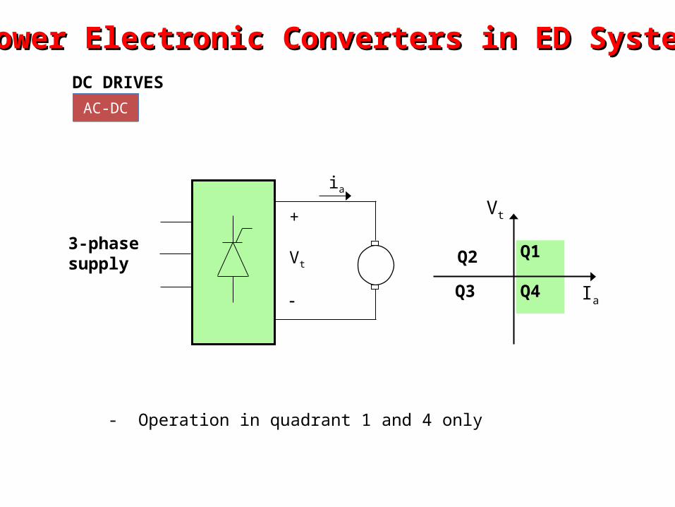
AC-DCAC-DC
Ia
Q1Q2
Q3 Q4
Vt
3-phasesupply
+
Vt
ia
- Operation in quadrant 1 and 4 only
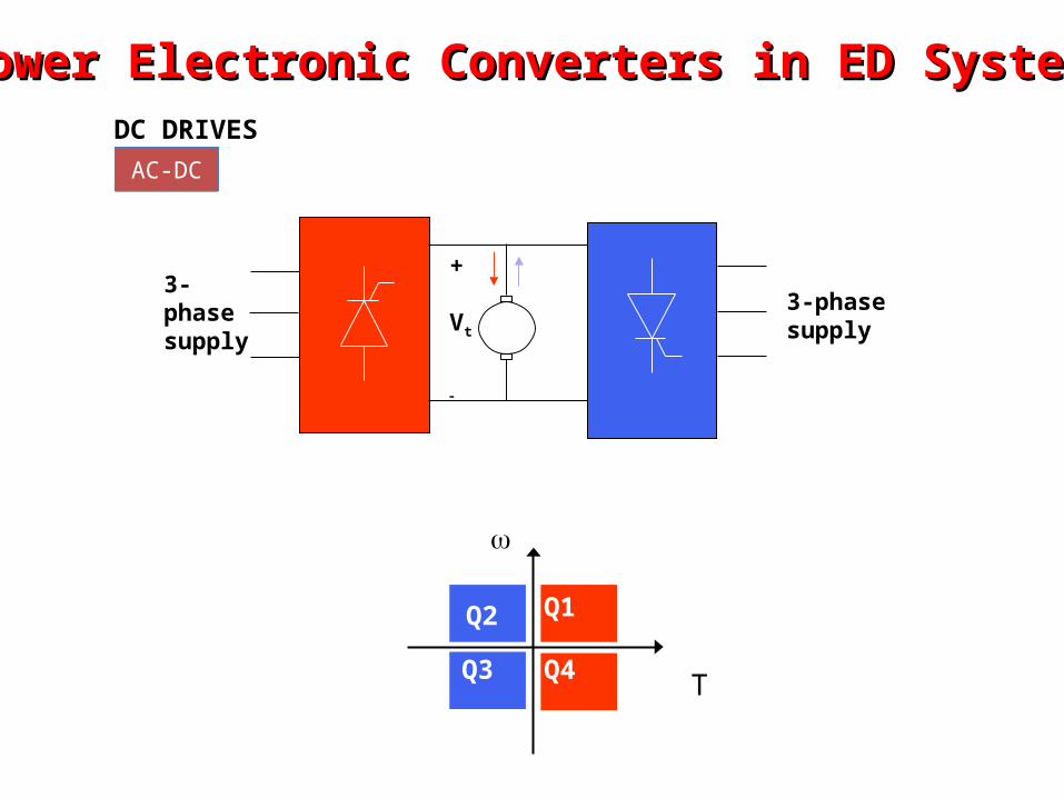
Power Electronic Converters in ED SystemsPower Electronic Converters in ED SystemsDC DRIVES
AC-DCAC-DC
Q1Q2
Q3 Q4
T
3-phasesupply
3-phasesupply
+
Vt
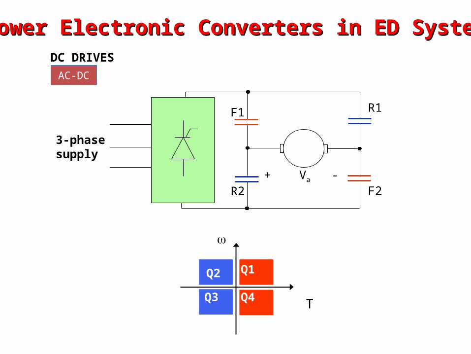
Power Electronic Converters in ED SystemsPower Electronic Converters in ED SystemsDC DRIVES
AC-DCAC-DC
Q1Q2
Q3 Q4
T
F1
F2
R1
R2+ Va -
3-phasesupply
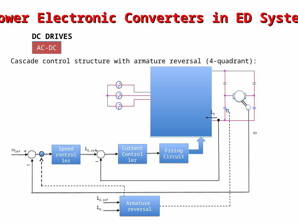
Power Electronic Converters in ED SystemsPower Electronic Converters in ED SystemsDC DRIVES
AC-DCAC-DC
Cascade control structure with armature reversal (4-quadrant):
Speedcontroller
Speedcontroller
CurrentController
CurrentController
FiringCircuitFiringCircuit
Armature reversal
Armature reversal
iD
iD,ref
iD,ref
iD,
ref + +
__
Power Electronic Converters in ED SystemsPower Electronic Converters in ED SystemsDC DRIVES
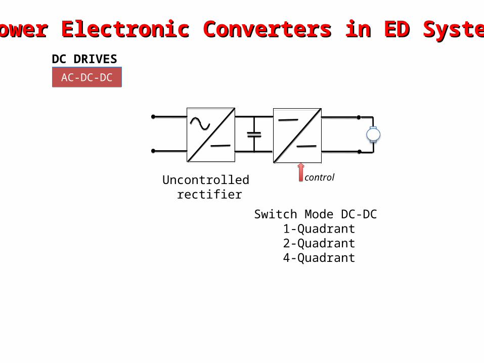
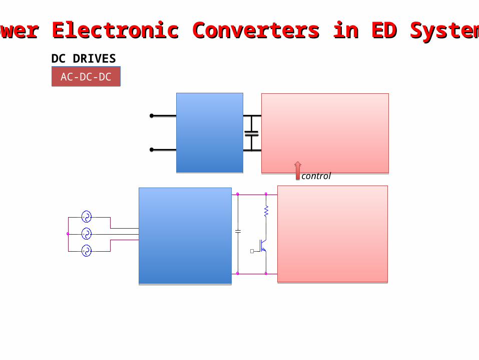
AC-DC-DCAC-DC-DC
controlUncontrolled rectifier
Switch Mode DC-DC1-Quadrant2-Quadrant4-Quadrant
Power Electronic Converters in ED SystemsPower Electronic Converters in ED SystemsDC DRIVES
AC-DC-DCAC-DC-DC
control
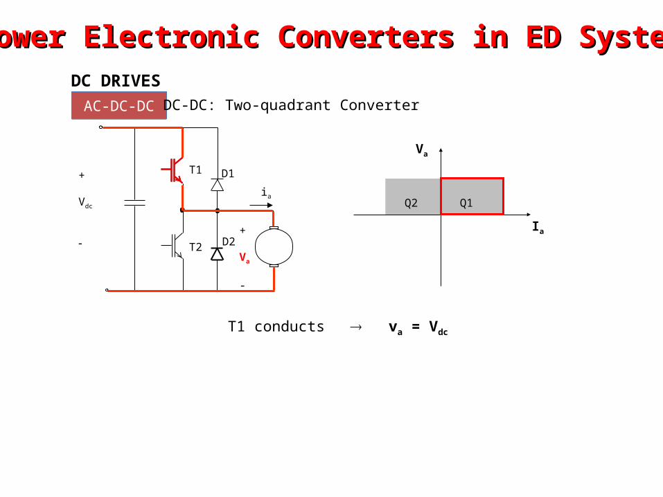
T1 conducts va = Vdc
Q1Q2
Va
Ia
T1
T2
D1
+
Va
-
D2
ia
+
Vdc
DC DRIVES
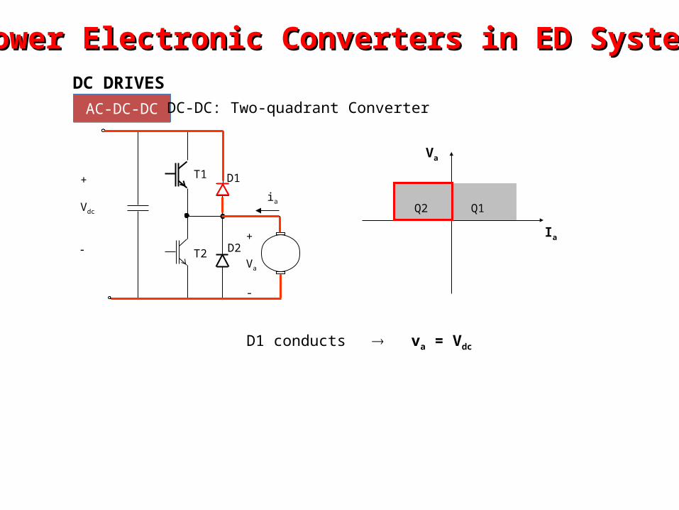
AC-DC-DCAC-DC-DC DC-DC: Two-quadrant Converter
Power Electronic Converters in ED SystemsPower Electronic Converters in ED Systems
Q1Q2
Va
Ia
T1
T2
D1
+
Va
-
D2
ia
+
Vdc
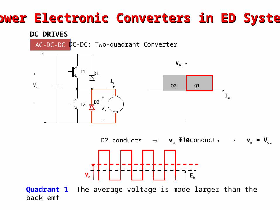
D2 conducts va = 0
Va Eb
T1 conducts va = Vdc
Quadrant 1 The average voltage is made larger than the back emf
DC DRIVES
AC-DC-DCAC-DC-DC DC-DC: Two-quadrant Converter
Power Electronic Converters in ED SystemsPower Electronic Converters in ED Systems
Q1Q2
Va
Ia
T1
T2
D1
+
Va
-
D2
ia
+
Vdc
D1 conducts va = Vdc
DC DRIVES
AC-DC-DCAC-DC-DC DC-DC: Two-quadrant Converter
Power Electronic Converters in ED SystemsPower Electronic Converters in ED Systems
Q1Q2
Va
Ia
T1
T2
D1
+
Va
-
D2
ia
+
Vdc
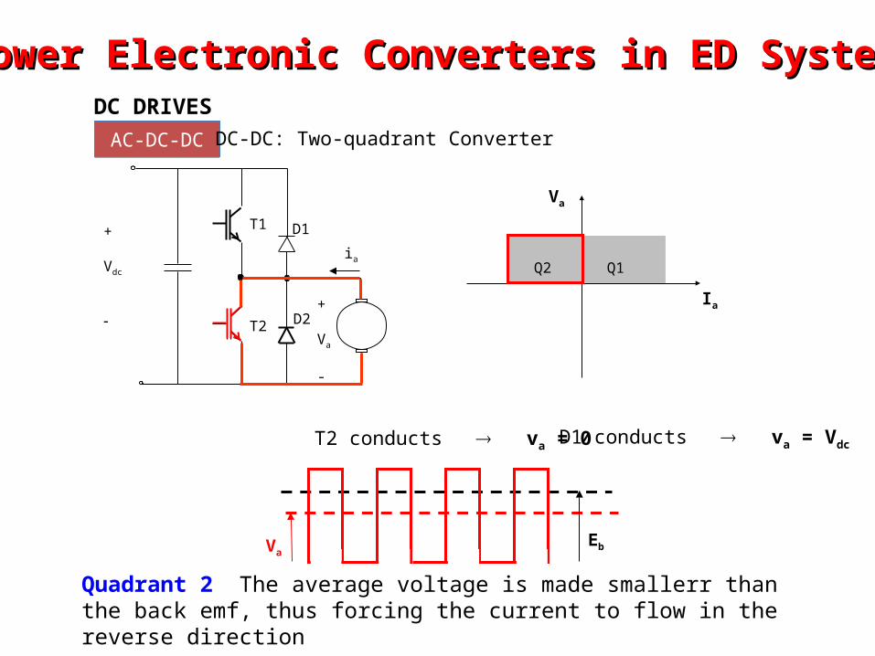
T2 conducts va = 0
VaEb
D1 conducts va = Vdc
Quadrant 2 The average voltage is made smallerr than the back emf, thus forcing the current to flow in the reverse direction
DC DRIVES
AC-DC-DCAC-DC-DC DC-DC: Two-quadrant Converter
Power Electronic Converters in ED SystemsPower Electronic Converters in ED Systems
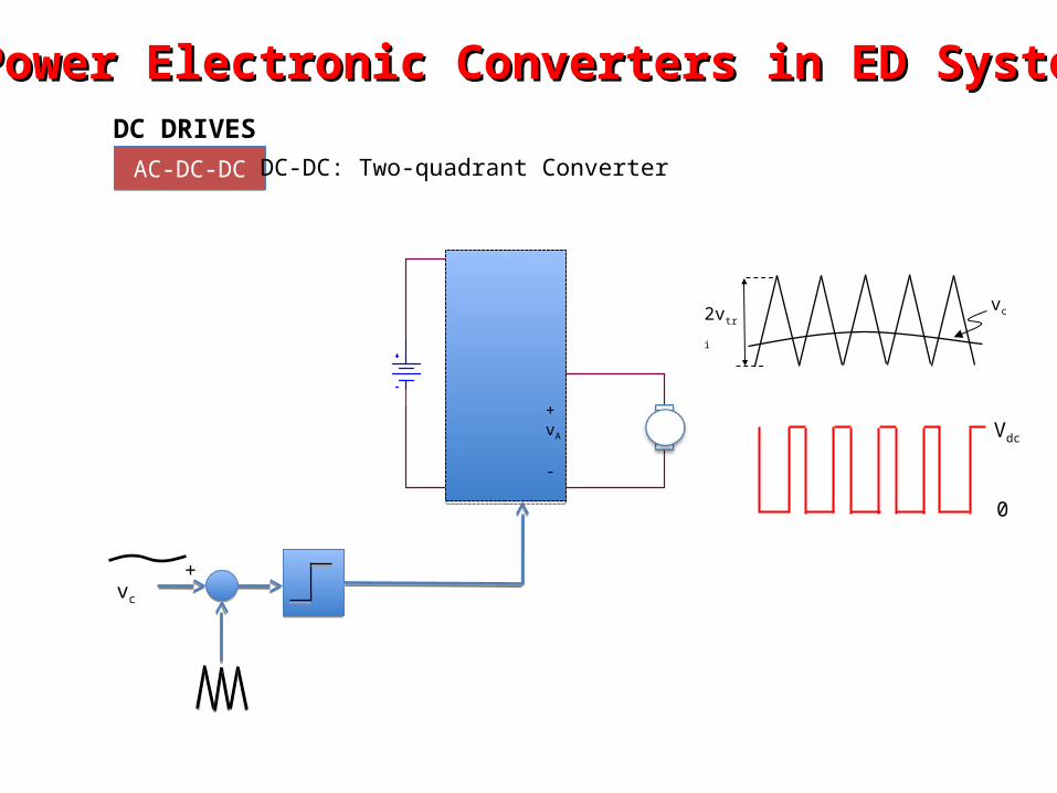
DC DRIVES
AC-DC-DCAC-DC-DC DC-DC: Two-quadrant Converter
+vc
2vtri
vc
+vA
-
Vdc
0
Power Electronic Converters in ED SystemsPower Electronic Converters in ED Systems
leg A leg B
+ Va Q1
Q4
Q3
Q2
D1 D3
D2D4
+
Vdc
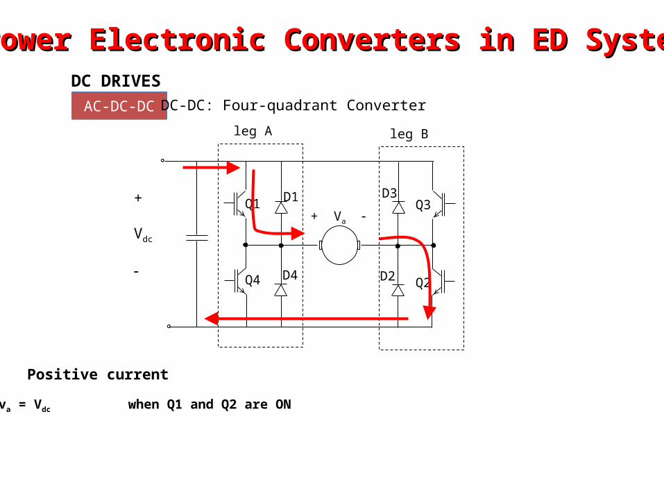
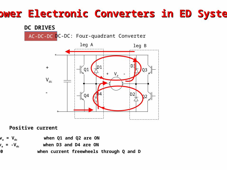
va = Vdc when Q1 and Q2 are ON
Positive current
Power Electronic Converters in ED SystemsPower Electronic Converters in ED SystemsDC DRIVES
AC-DC-DCAC-DC-DC DC-DC: Four-quadrant Converter
leg A leg B
+ Va Q1
Q4
Q3
Q2
D1 D3
D2D4
+
Vdc
va = -Vdc when D3 and D4 are ON
va = Vdc when Q1 and Q2 are ON
va = 0 when current freewheels through Q and D
Positive current
Power Electronic Converters in ED SystemsPower Electronic Converters in ED SystemsDC DRIVES
AC-DC-DCAC-DC-DC DC-DC: Four-quadrant Converter
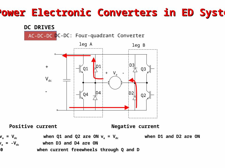
va = -Vdc when D3 and D4 are ON
va = Vdc when Q1 and Q2 are ON
va = 0 when current freewheels through Q and D
Positive current
va = Vdc when D1 and D2 are ON
Negative current
leg A leg B
+ Va Q1
Q4
Q3
Q2
D1 D3
D2D4
+
Vdc
Power Electronic Converters in ED SystemsPower Electronic Converters in ED SystemsDC DRIVES
AC-DC-DCAC-DC-DC DC-DC: Four-quadrant Converter
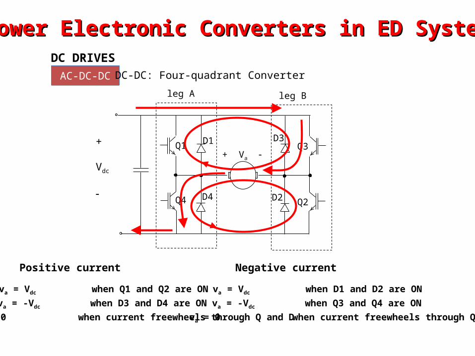
va = -Vdc when D3 and D4 are ON
va = Vdc when Q1 and Q2 are ON
va = 0 when current freewheels through Q and D
Positive current
va = -Vdc when Q3 and Q4 are ON
va = Vdc when D1 and D2 are ON
va = 0 when current freewheels through Q and D
Negative current
leg A leg B
+ Va Q1
Q4
Q3
Q2
D1 D3
D2D4
+
Vdc
Power Electronic Converters in ED SystemsPower Electronic Converters in ED SystemsDC DRIVES
AC-DC-DCAC-DC-DC DC-DC: Four-quadrant Converter
Power Electronic Converters in ED SystemsPower Electronic Converters in ED SystemsDC DRIVES
AC-DC-DCAC-DC-DC
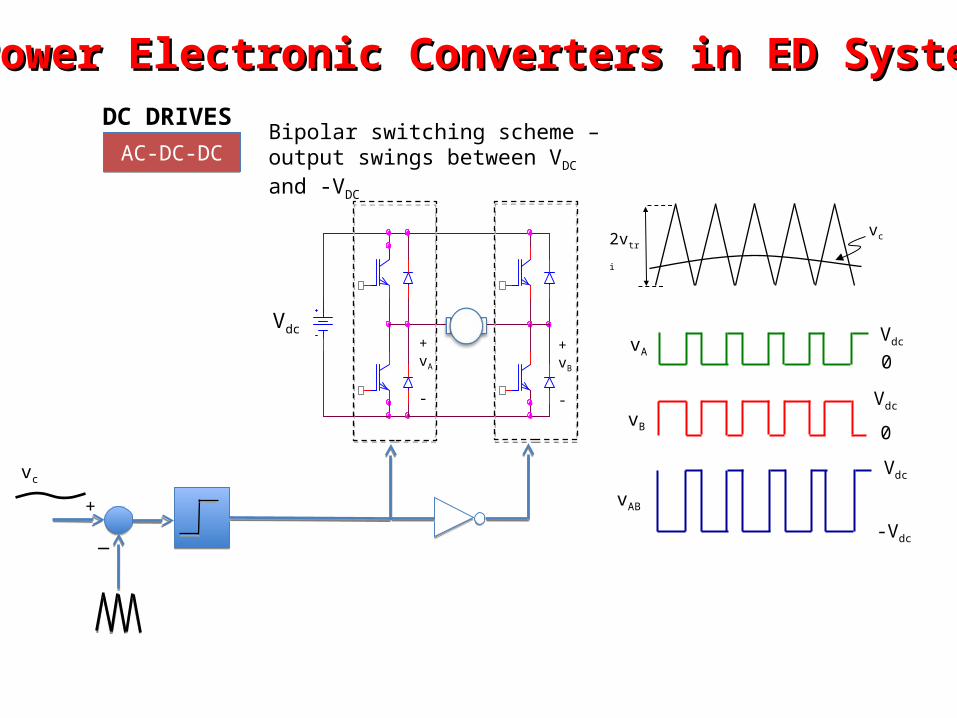
vAB
Vdc
-Vdc
Vdc
0vB
vAVdc
0
2vtri
vc
vc
+
_
Vdc+vA
-
+vB
-
Bipolar switching scheme – output swings between VDC and -VDC
Power Electronic Converters in ED SystemsPower Electronic Converters in ED SystemsDC DRIVES
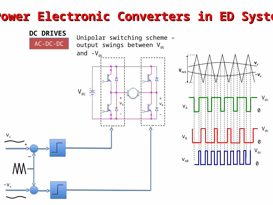
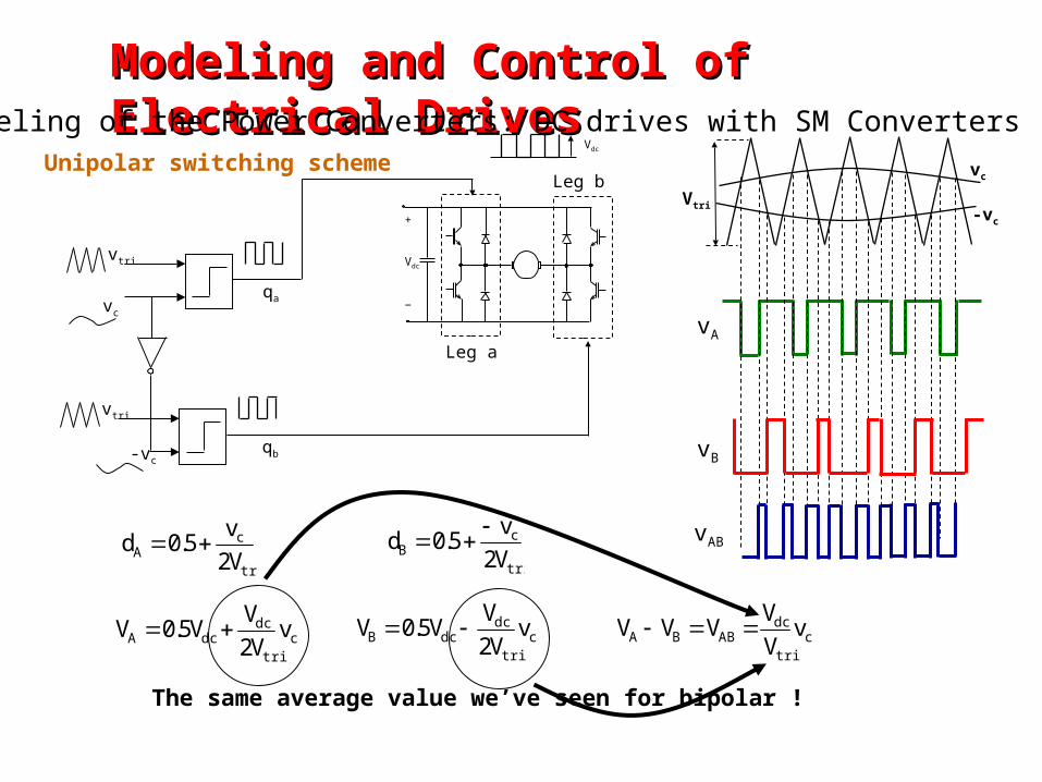
AC-DC-DCAC-DC-DCUnipolar switching scheme – output swings between Vdc and -Vdc
Vtri
vc
-vc
vc
+
_
Vdc+vA
-
+vB
-
-vc
vA
Vdc
0
vB
Vdc
0
vAB
Vdc
0
Power Electronic Converters in ED SystemsPower Electronic Converters in ED SystemsDC DRIVES
AC-DC-DCAC-DC-DC
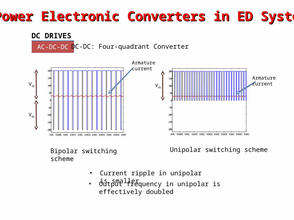
Bipolar switching scheme
0.04 0.0405 0.041 0.0415 0.042 0.0425 0.043 0.0435 0.044 0.0445 0.045
-200
-150
-100
-50
0
50
100
150
200
Unipolar switching scheme
0.04 0.0405 0.041 0.0415 0.042 0.0425 0.043 0.0435 0.044 0.0445 0.045
-200
-150
-100
-50
0
50
100
150
200
• Current ripple in unipolar is smaller
• Output frequency in unipolar is effectively doubled
Vdc
Vdc
Vdc
DC-DC: Four-quadrant Converter
Armature current
Armature current
Power Electronic Converters in ED SystemsPower Electronic Converters in ED Systems
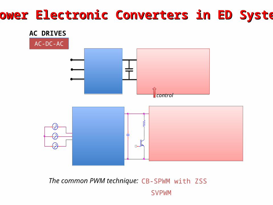
AC DRIVES
AC-DC-ACAC-DC-AC
control
The common PWM technique: CB-SPWM with ZSS
SVPWM
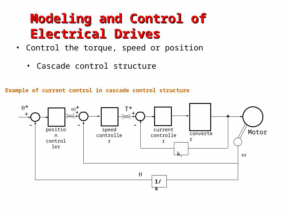
Modeling and Control of Electrical DrivesModeling and Control of Electrical Drives
• Control the torque, speed or position
• Cascade control structure
Motor
Example of current control in cascade control structure
converterspeed
controllerposition
controller
+*
1/s
+ +
current
controller
T**
kT
Modeling and Control of Electrical DrivesModeling and Control of Electrical Drives
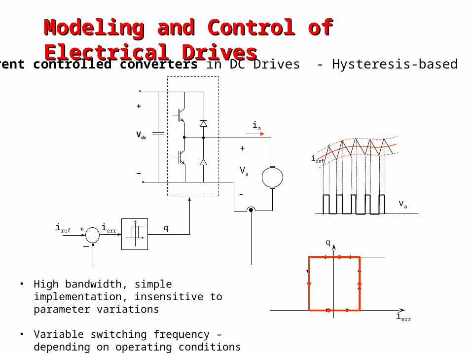
Current controlled converters in DC Drives - Hysteresis-based
iref
+
Vdc
−
ia
iref
va
+
Va
ierr
ierr
q
q
• High bandwidth, simple implementation, insensitive to parameter variations
• Variable switching frequency – depending on operating conditions
+
_
Modeling and Control of Electrical DrivesModeling and Control of Electrical Drives
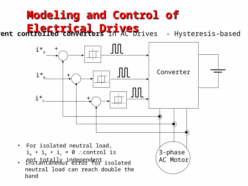
Current controlled converters in AC Drives - Hysteresis-based
3-phaseAC Motor
+
+
+
i*a
i*b
i*c
Converter
• For isolated neutral load, ia + ib + ic = 0 control is not totally independent
• Instantaneous error for isolated neutral load can reach double the band
Modeling and Control of Electrical DrivesModeling and Control of Electrical Drives
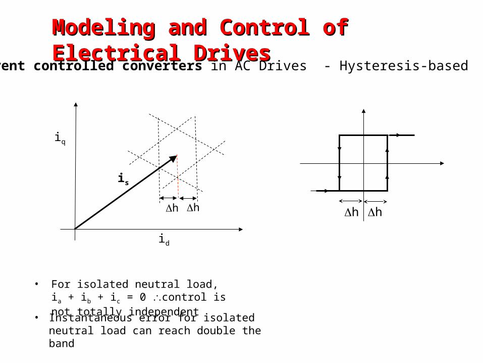
Current controlled converters in AC Drives - Hysteresis-based
id
iq
is
hh hh
• For isolated neutral load, ia + ib + ic = 0 control is not totally independent
• Instantaneous error for isolated neutral load can reach double the band
Modeling and Control of Electrical DrivesModeling and Control of Electrical Drives
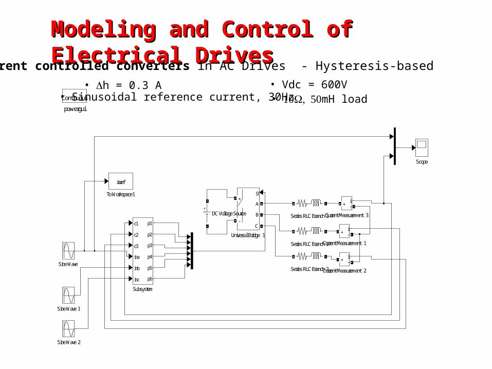
Current controlled converters in AC Drives - Hysteresis-based
powergui
Continuous
Universal Bridge 1
g
A
B
C
+
-
To Workspace1
iaref
Subsystem
c1
c2
c3
ina
inb
inc
p1
p2
p3
p4
p5
p6
Sine Wave 2
Sine Wave 1
Sine Wave
Series RLC Branch 3
Series RLC Branch 2
Series RLC Branch 1
Scope
DC Voltage Source Current Measurement 3
i+ -
Current Measurement 2
i+ -
Current Measurement 1
i+ -
• h = 0.3 A• Sinusoidal reference current, 30Hz
• Vdc = 600V• mH load
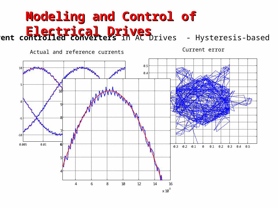
Modeling and Control of Electrical DrivesModeling and Control of Electrical Drives
Current controlled converters in AC Drives - Hysteresis-based
0.005 0.01 0.015 0.02 0.025 0.03
-10
-5
0
5
10
Actual and reference currents Current error
-0.5 -0.4 -0.3 -0.2 -0.1 0 0.1 0.2 0.3 0.4 0.5
-0.5
-0.4
-0.3
-0.2
-0.1
0
0.1
0.2
0.3
0.4
0.5
4 6 8 10 12 14 16
x 10-3
4
5
6
7
8
9
10
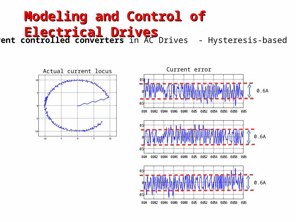
Modeling and Control of Electrical DrivesModeling and Control of Electrical Drives
Current controlled converters in AC Drives - Hysteresis-based
-10 -5 0 5 10
-10
-5
0
5
10
Actual current locus
0.04 0.042 0.044 0.046 0.048 0.05 0.052 0.054 0.056 0.058 0.06
-0.5
0
0.5
0.04 0.042 0.044 0.046 0.048 0.05 0.052 0.054 0.056 0.058 0.06
-0.5
0
0.5
0.04 0.042 0.044 0.046 0.048 0.05 0.052 0.054 0.056 0.058 0.06
-0.5
0
0.5
0.6A
0.6A
0.6A
Current error
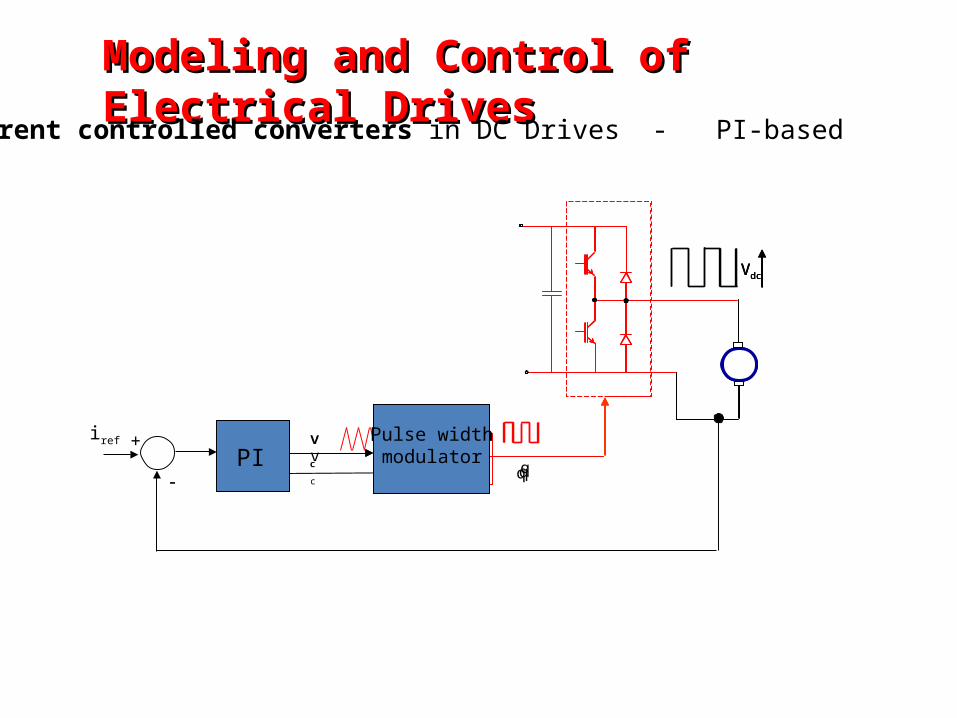
vtri
Vdc
qvc
q
Vdc
Pulse widthmodulator
vc
Vdc
Pulse widthmodulator
vciref
PI+
q
Modeling and Control of Electrical DrivesModeling and Control of Electrical Drives
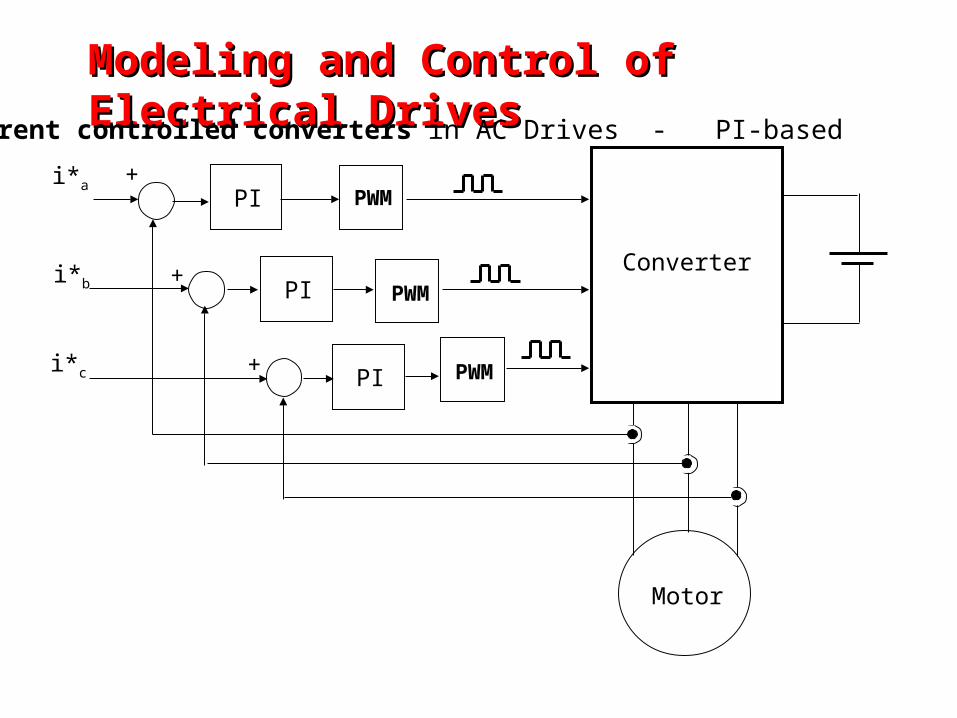
Current controlled converters in DC Drives - PI-based
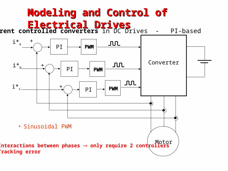
Motor
+
+
+
i*a
i*b
i*c
Converter
PWM
PWM
PWM
PWM
PWM
PWM
• Sinusoidal PWM
PI
PI
PI
• Interactions between phases only require 2 controllers• Tracking error
Modeling and Control of Electrical Modeling and Control of Electrical DrivesDrives
Current controlled converters in DC Drives - PI-based
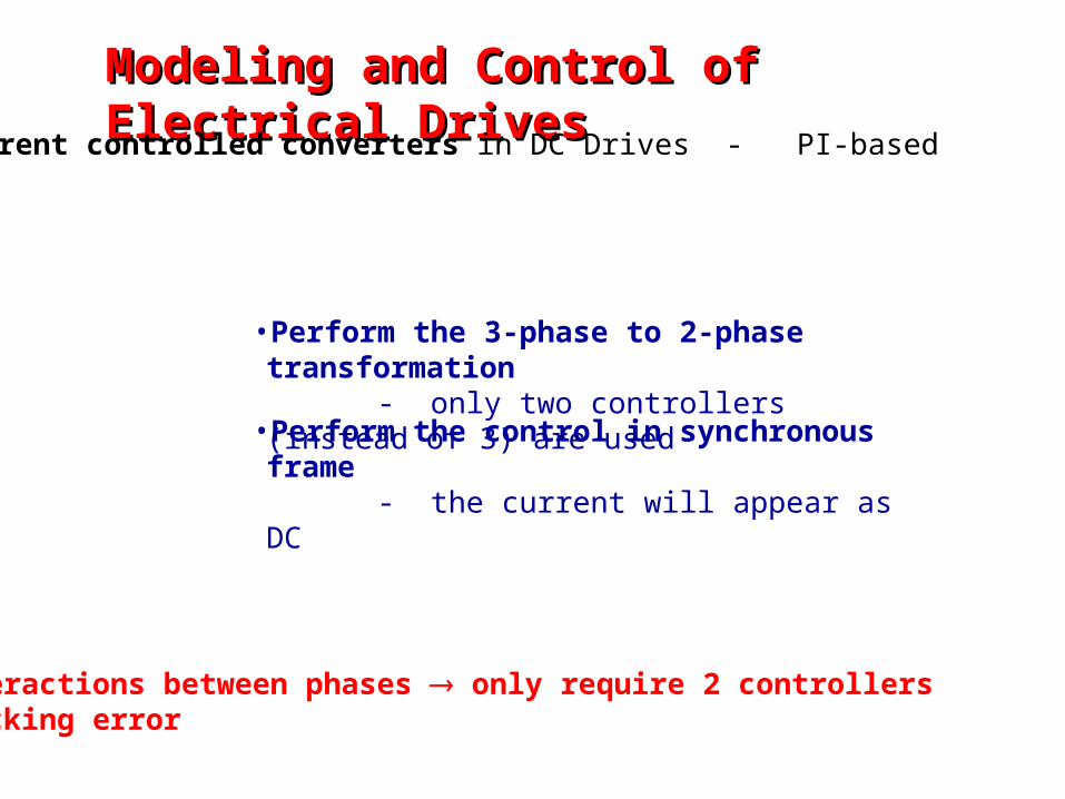
•Interactions between phases only require 2 controllers•Tracking error
•Perform the control in synchronous frame - the current will appear as DC
•Perform the 3-phase to 2-phase transformation - only two controllers (instead of 3) are used
Modeling and Control of Electrical DrivesModeling and Control of Electrical Drives
Current controlled converters in DC Drives - PI-based
Motor
i*a
i*b
i*c
Converter
PWM
+
+
+
PWM
PWM
PI
PI
PI
Modeling and Control of Electrical DrivesModeling and Control of Electrical Drives
Current controlled converters in AC Drives - PI-based
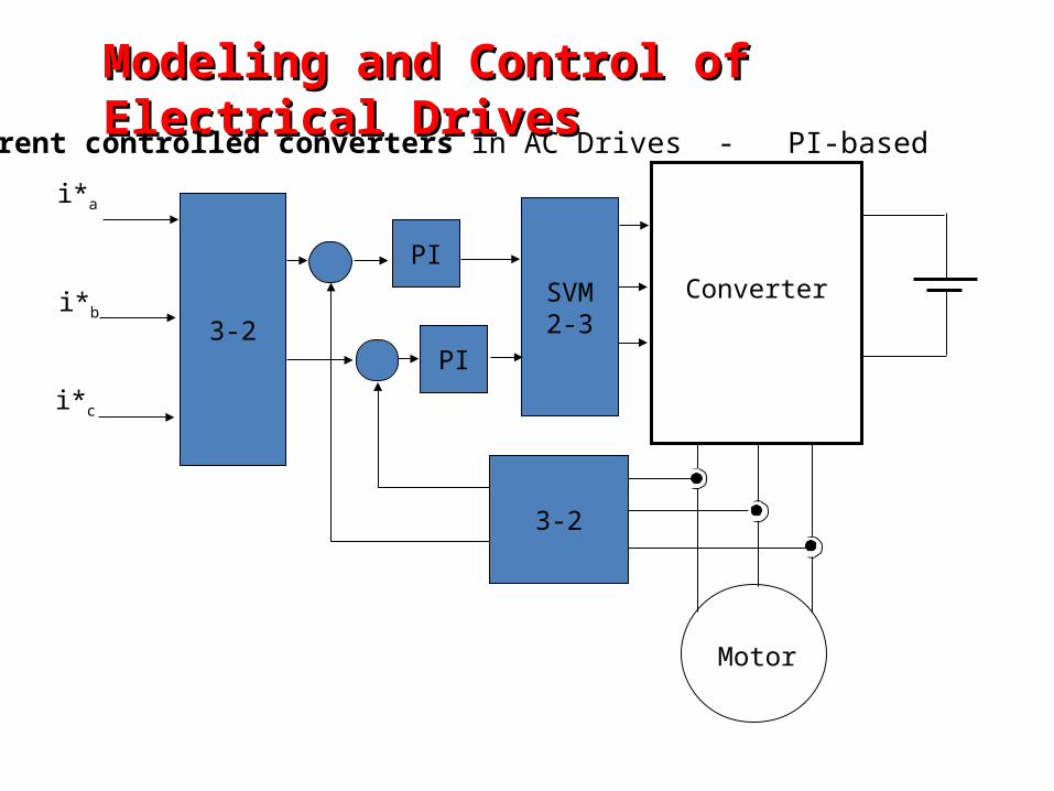
Motor
i*a
i*b
i*c
Converter
3-2
3-2
SVM2-3
PI
PI
Modeling and Control of Electrical DrivesModeling and Control of Electrical Drives
Current controlled converters in AC Drives - PI-based
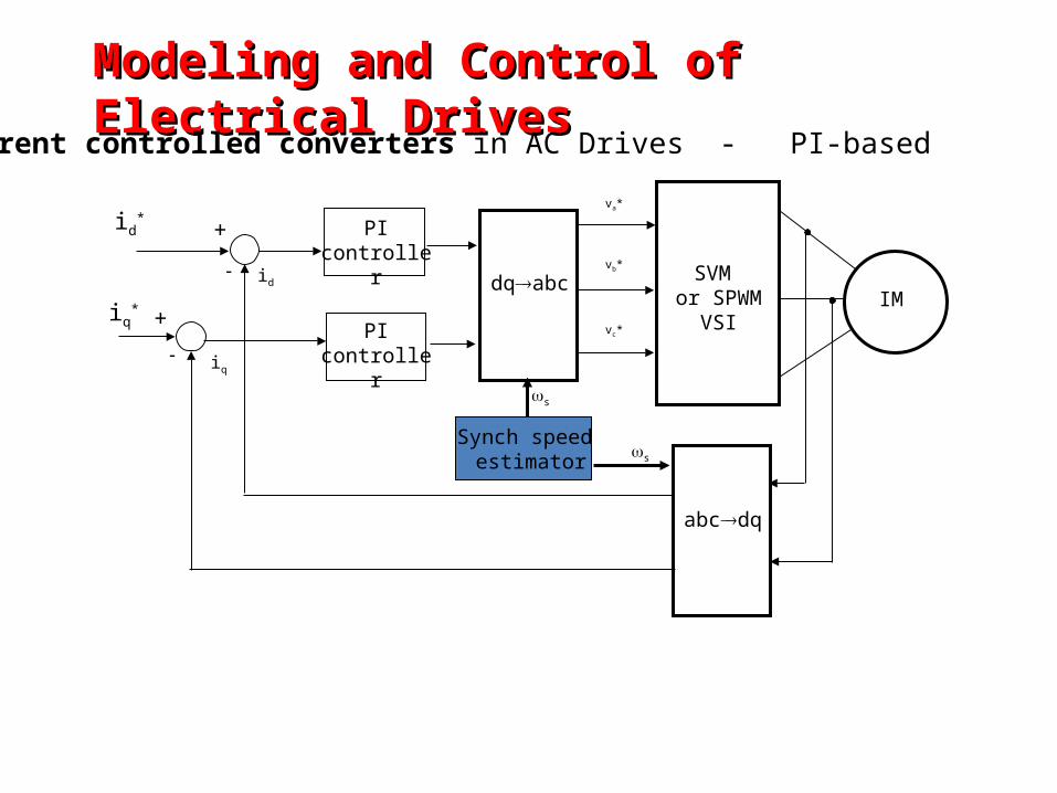
id*
iq*
PIcontroller
dqabc
abcdq
SVM or SPWM
VSIIM
va*
vb*
vc*
id
iq
+
+
PIcontroller
Synch speed estimator
s
s
Modeling and Control of Electrical DrivesModeling and Control of Electrical Drives
Current controlled converters in AC Drives - PI-based
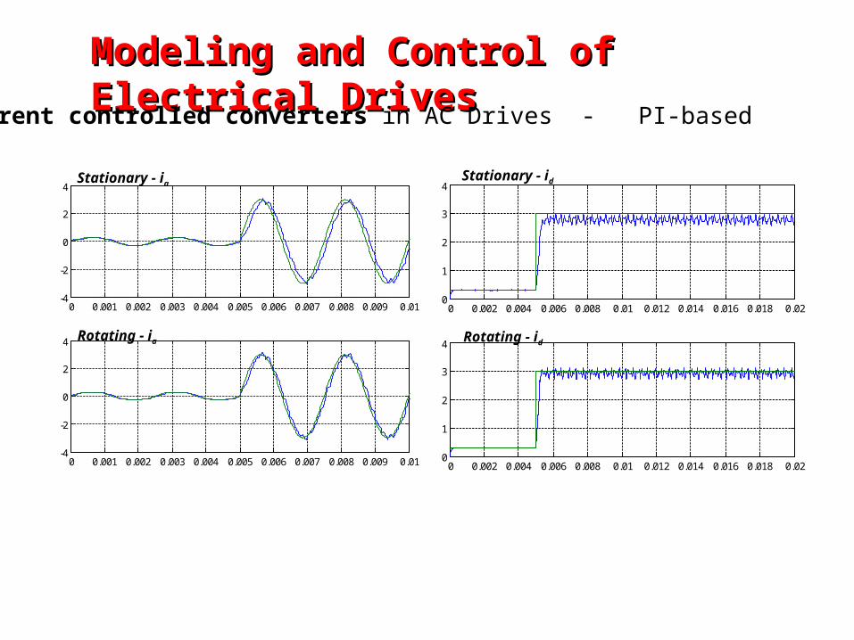
Modeling and Control of Electrical Modeling and Control of Electrical DrivesDrives
0 0.001 0.002 0.003 0.004 0.005 0.006 0.007 0.008 0.009 0.01-4
-2
0
2
4
0 0.001 0.002 0.003 0.004 0.005 0.006 0.007 0.008 0.009 0.01-4
-2
0
2
4
0 0.002 0.004 0.006 0.008 0.01 0.012 0.014 0.016 0.018 0.020
1
2
3
4
0 0.002 0.004 0.006 0.008 0.01 0.012 0.014 0.016 0.018 0.020
1
2
3
4
Stationary - iaStationary - id
Rotating - ia Rotating - id
Current controlled converters in AC Drives - PI-based
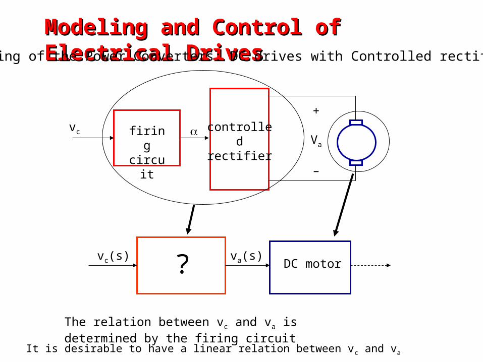
Modeling and Control of Electrical DrivesModeling and Control of Electrical DrivesModeling of the Power Converters: DC drives with Controlled rectifier
firingcircuit
controlled rectifier
+
Va
–
vc
va(s)vc(s)DC motor
The relation between vc and va is determined by the firing circuit
?
It is desirable to have a linear relation between vc and va
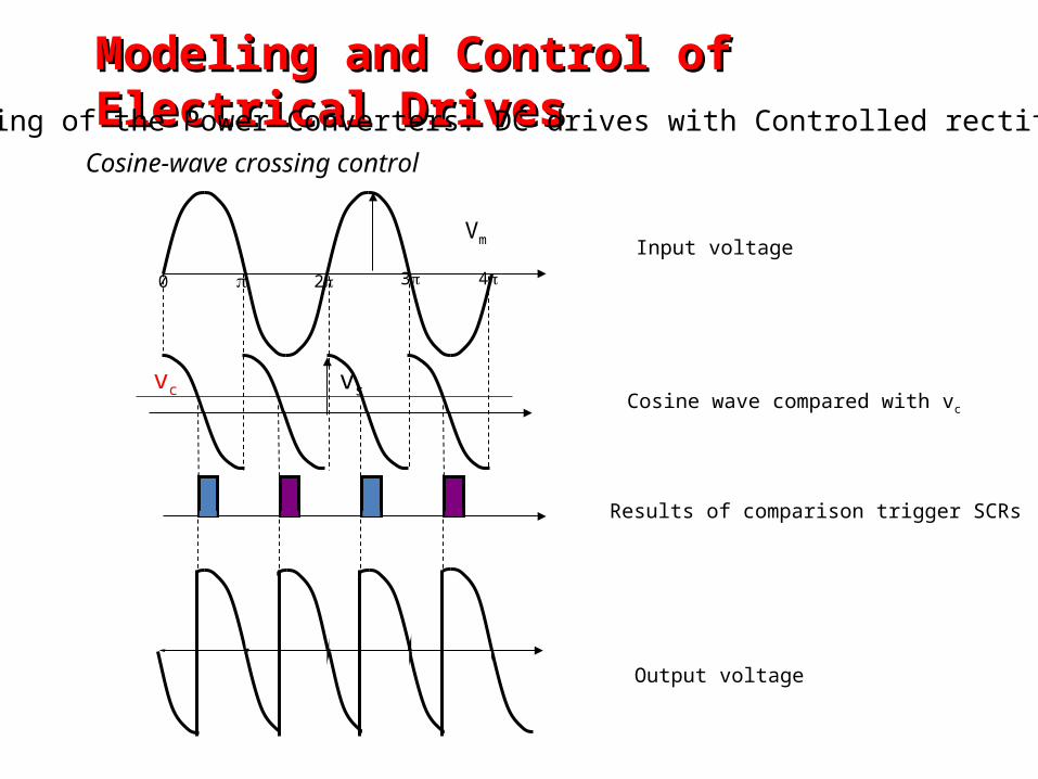
Modeling and Control of Electrical DrivesModeling and Control of Electrical DrivesModeling of the Power Converters: DC drives with Controlled rectifier
Cosine-wave crossing control
Vm
vsvc
0 2 3 4
Input voltage
Cosine wave compared with vc
Results of comparison trigger SCRs
Output voltage
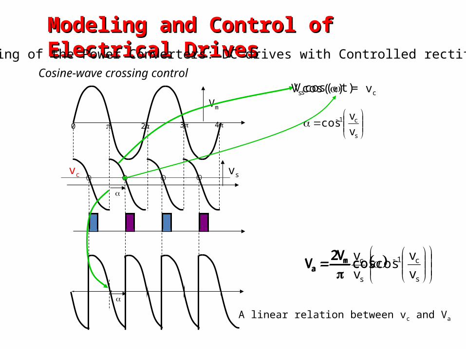
Modeling and Control of Electrical DrivesModeling and Control of Electrical DrivesModeling of the Power Converters: DC drives with Controlled rectifier
Cosine-wave crossing control
Vm
vsvc
0 2 3 4
Vscos(t)Vscos() = vc
s
c1
vv
cos
cosV2
V ma
s
c1ma v
vcoscos
V2V
s
cma v
vV2V
A linear relation between vc and Va
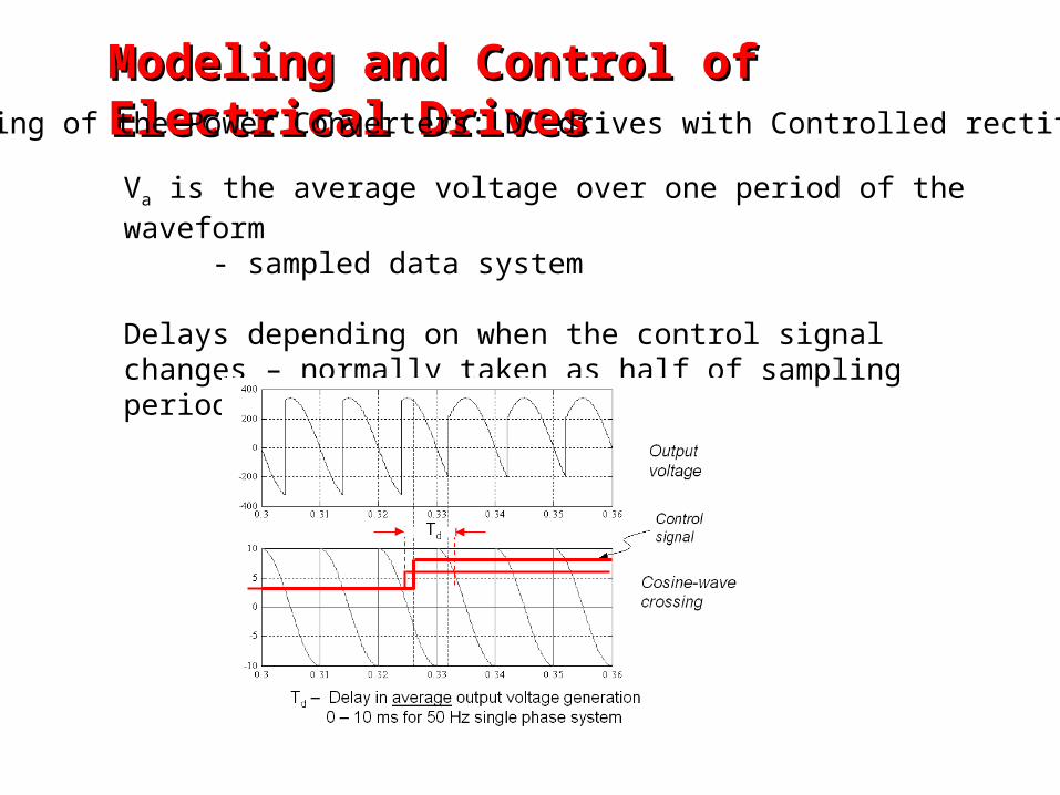
Va is the average voltage over one period of the waveform - sampled data system
Delays depending on when the control signal changes – normally taken as half of sampling period
Modeling and Control of Electrical DrivesModeling and Control of Electrical DrivesModeling of the Power Converters: DC drives with Controlled rectifier
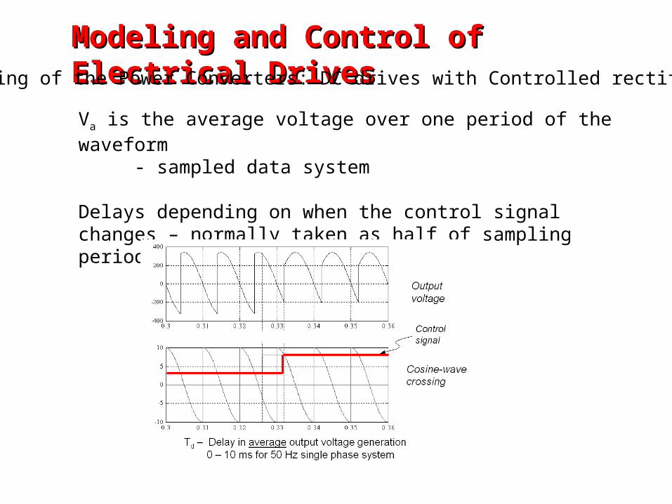
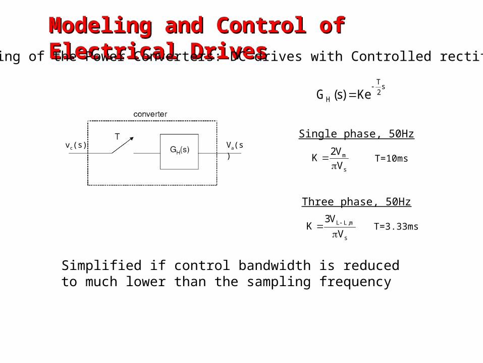
s2
T
H Ke)s(G
vc(s) Va(s)
s
m
V
V2K
Single phase, 50Hz
T=10ms
s
m,LL
V
V3K
Three phase, 50Hz
T=3.33ms
Simplified if control bandwidth is reduced to much lower than the sampling frequency
Modeling and Control of Electrical DrivesModeling and Control of Electrical DrivesModeling of the Power Converters: DC drives with Controlled rectifier
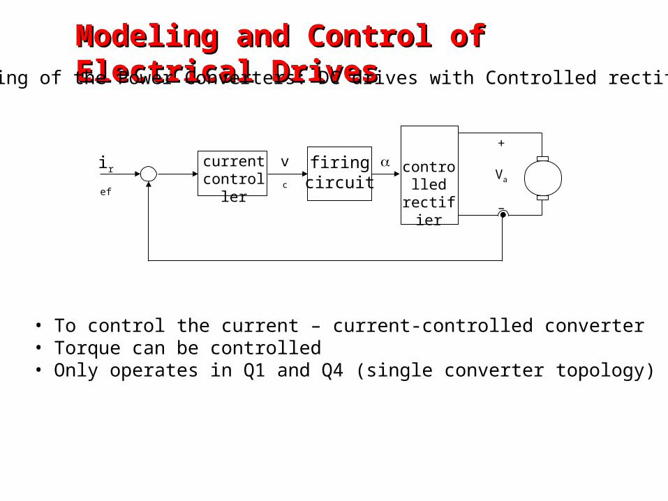
firingcircuit
currentcontroller
controlled rectifier
+
Va
–
vciref
• To control the current – current-controlled converter• Torque can be controlled• Only operates in Q1 and Q4 (single converter topology)
Modeling and Control of Electrical DrivesModeling and Control of Electrical DrivesModeling of the Power Converters: DC drives with Controlled rectifier
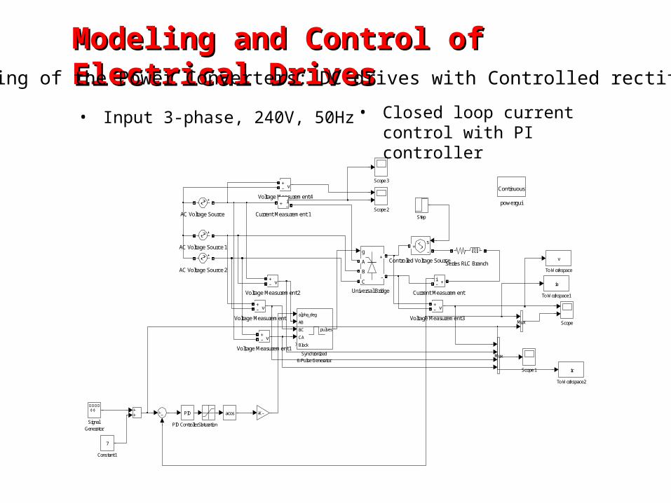
Modeling and Control of Electrical DrivesModeling and Control of Electrical DrivesModeling of the Power Converters: DC drives with Controlled rectifier
powergui
ContinuousVoltage Measurement4
v+-
Voltage Measurement3
v+-
Voltage Measurement2
v+-
Voltage Measurement1
v+-
Voltage Measurement
v+-
Universal Bridge
g
A
B
C
+
-
acos
To Workspace2
ir
To Workspace1
ia
To Workspace
v
Synchronized6-Pulse Generator
alpha_deg
AB
BC
CA
Block
pulses
Step
SignalGenerator
Series RLC Branch
Scope3
Scope2
Scope1
Scope
SaturationPID Controller 1
PID
Mux
Mux
-K-
Current Measurement 1
i+ -
Current Measurement
i +-
Controlled Voltage Source
s
-+
Constant1
7
AC Voltage Source2
AC Voltage Source1
AC Voltage Source
• Input 3-phase, 240V, 50Hz • Closed loop current control with PI controller
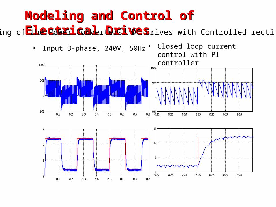
Modeling and Control of Electrical DrivesModeling and Control of Electrical DrivesModeling of the Power Converters: DC drives with Controlled rectifier
• Input 3-phase, 240V, 50Hz • Closed loop current control with PI controller
0.1 0.2 0.3 0.4 0.5 0.6 0.7 0.8-500
0
500
1000
0.1 0.2 0.3 0.4 0.5 0.6 0.7 0.80
5
10
15
Voltage
Current
0.22 0.23 0.24 0.25 0.26 0.27 0.28-500
0
500
1000
0.22 0.23 0.24 0.25 0.26 0.27 0.280
5
10
15
Modeling and Control of Electrical DrivesModeling and Control of Electrical DrivesModeling of the Power Converters: DC drives with SM Converters
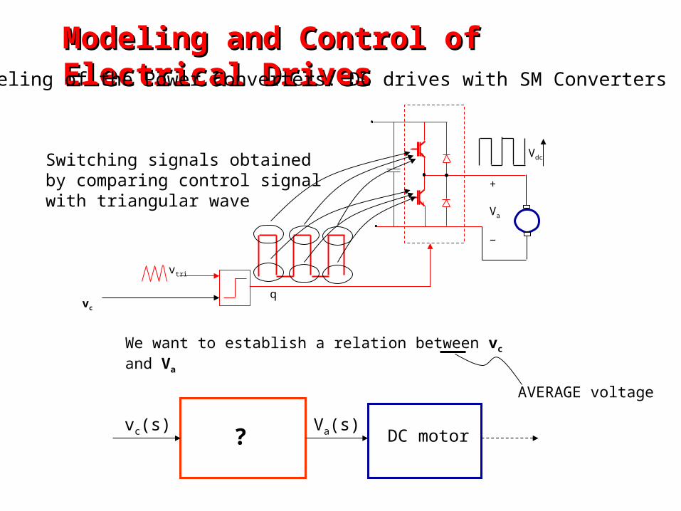
vc
+
Va
−
vtri
Vdc
q
Switching signals obtained by comparing control signal with triangular wave
Va(s)vc(s)DC motor
We want to establish a relation between vc and Va
?
AVERAGE voltage
Modeling and Control of Electrical DrivesModeling and Control of Electrical DrivesModeling of the Power Converters: DC drives with SM Converters
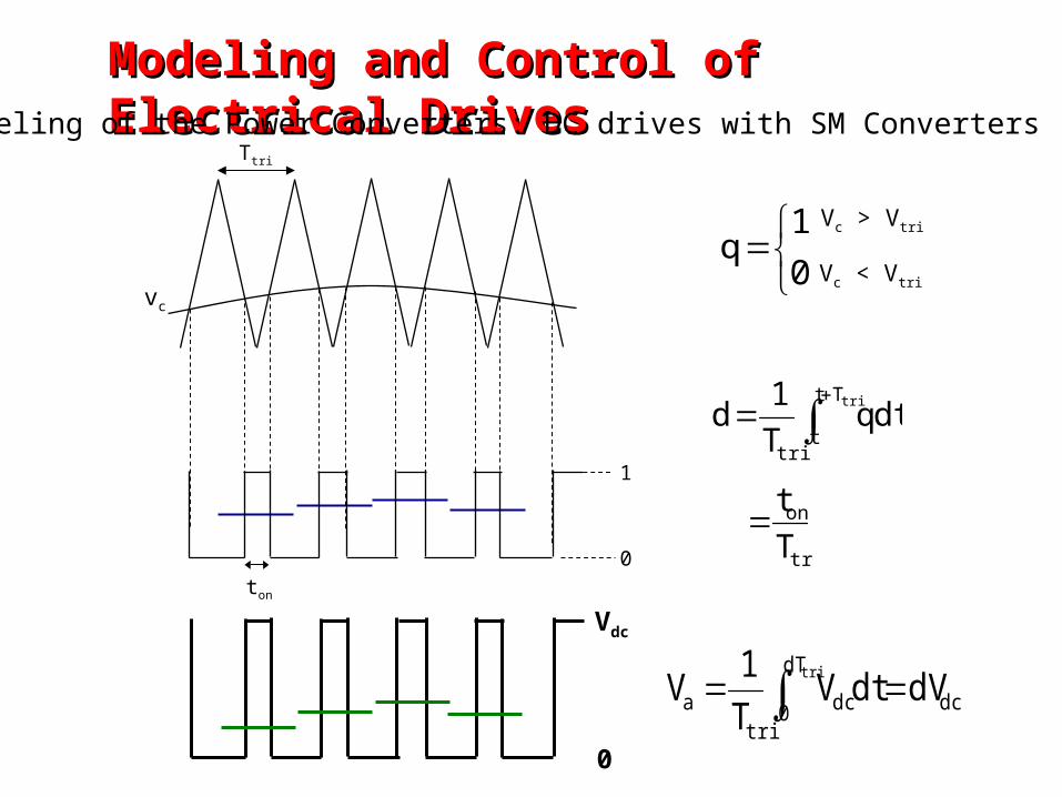
dtqT1
dtriTt
ttri
tri
on
Tt
Vdc
0
Ttri
ton
0
1
01
qVc > Vtri
Vc < Vtrivc
dc
dT
0 dctri
a dVdtVT1
Vtri
Modeling and Control of Electrical DrivesModeling and Control of Electrical DrivesModeling of the Power Converters: DC drives with SM Converters
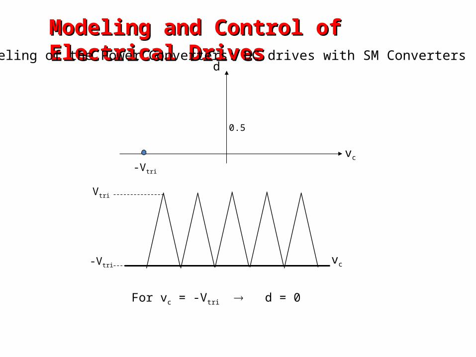
-Vtri
Vtri
-Vtri
vc
d
vc
0.5
For vc = -Vtri d = 0
Modeling and Control of Electrical DrivesModeling and Control of Electrical DrivesModeling of the Power Converters: DC drives with SM Converters
Modeling and Control of Electrical DrivesModeling and Control of Electrical DrivesModeling of the Power Converters: DC drives with SM Converters
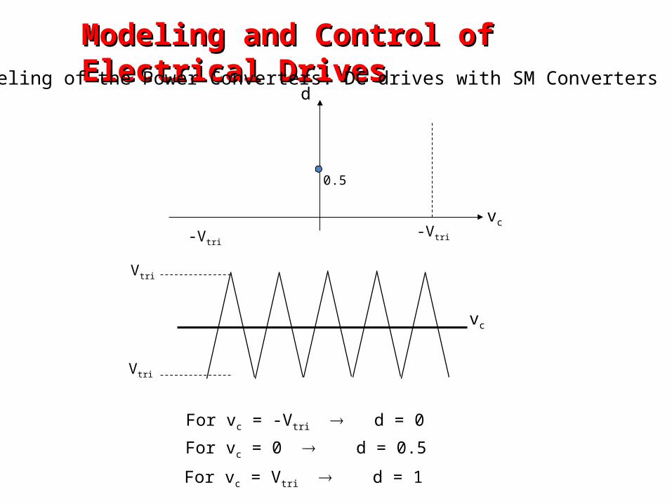
0.5
Vtri
Vtri
vc
d
vc
-Vtri-Vtri
For vc = -Vtri d = 0
For vc = 0 d = 0.5
For vc = Vtri d = 1
Modeling and Control of Electrical DrivesModeling and Control of Electrical DrivesModeling of the Power Converters: DC drives with SM Converters
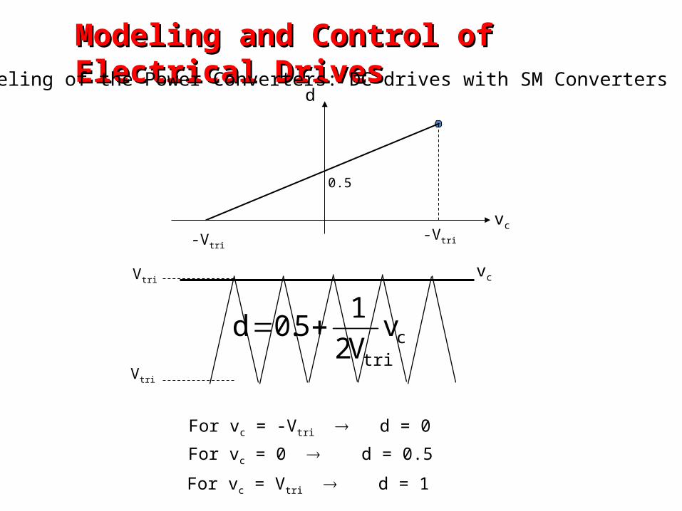
0.5
vc
d
-Vtri-Vtri
ctri
vV21
5.0d
Vtri
Vtri
vc
For vc = -Vtri d = 0
For vc = 0 d = 0.5
For vc = Vtri d = 1
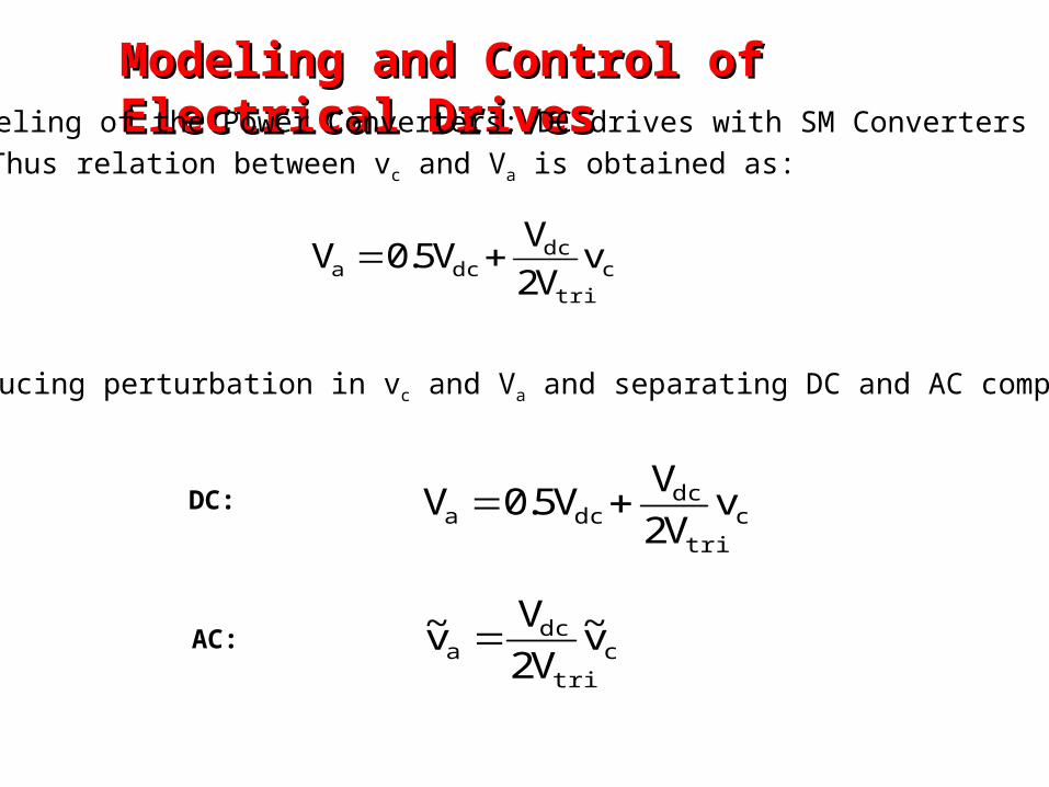
Thus relation between vc and Va is obtained as:
ctri
dcdca v
V2V
V5.0V
Introducing perturbation in vc and Va and separating DC and AC components:
ctri
dcdca v
V2V
V5.0V
ctri
dca v~
V2V
v~
DC:
AC:
Modeling and Control of Electrical DrivesModeling and Control of Electrical DrivesModeling of the Power Converters: DC drives with SM Converters
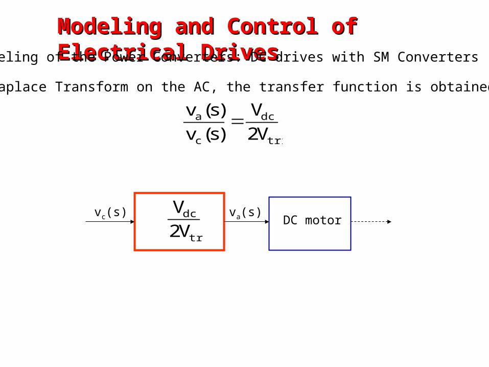
Taking Laplace Transform on the AC, the transfer function is obtained as:
tri
dc
c
a
V2V
)s(v)s(v
va(s)vc(s)DC motor
tri
dc
V2V
Modeling and Control of Electrical DrivesModeling and Control of Electrical DrivesModeling of the Power Converters: DC drives with SM Converters
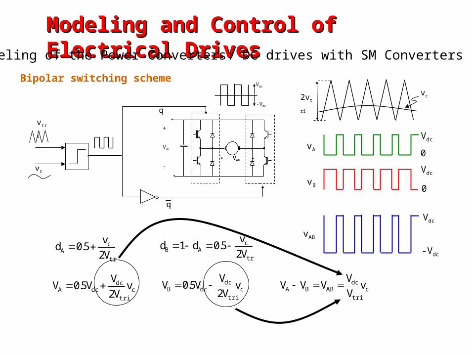
2vtri
vc
vc
vtri+
Vdc
−
q-Vdc
q
Vdc
+ VAB
vAB
Vdc
-Vdc
ctri
dcABBA v
VV
VVV
tri
cAB V2
v5.0d1d
ctri
dcdcB v
V2V
V5.0V
vB
Vdc
0
tri
cA V2
v5.0d
ctri
dcdcA v
V2V
V5.0V
vA
Vdc
0
Modeling and Control of Electrical DrivesModeling and Control of Electrical DrivesModeling of the Power Converters: DC drives with SM Converters
Bipolar switching scheme
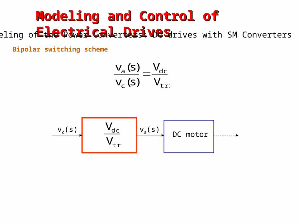
tri
dc
c
a
VV
)s(v)s(v
va(s)vc(s)DC motor
tri
dc
VV
Bipolar switching scheme
Modeling and Control of Electrical DrivesModeling and Control of Electrical DrivesModeling of the Power Converters: DC drives with SM Converters
+
Vdc
−vc
vtri
qa
Vdc
-vc
vtri
qb
Leg a
Leg b
The same average value we’ve seen for bipolar !
Vtri
vc
-vc
tri
cA V2
v5.0d
ctri
dcdcA v
V2V
V5.0V
vA
tri
cB V2
v5.0d
ctri
dcdcB v
V2V
V5.0V
vB
ctri
dcABBA v
VV
VVV
vAB
Unipolar switching scheme
Modeling and Control of Electrical DrivesModeling and Control of Electrical DrivesModeling of the Power Converters: DC drives with SM Converters

tri
dc
c
a
VV
)s(v)s(v
va(s)vc(s)DC motor
tri
dc
VV
Unipolar switching scheme
Modeling and Control of Electrical DrivesModeling and Control of Electrical DrivesModeling of the Power Converters: DC drives with SM Converters
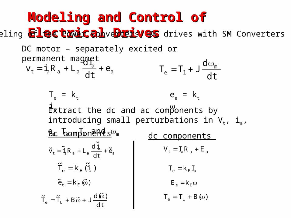
DC motor – separately excited or permanent magnet
Extract the dc and ac components by introducing small perturbations in Vt, ia, ea, Te, TL and m
aa
aaat edtdi
LRiv
Te = kt ia ee = kt
dtd
JTT mle
aa
aaat e~dti~
dLRi
~v~
)i~(kT
~aEe
)~(ke~ Ee
dt)~(d
J~BT~
T~
Le
ac components
aaat ERIV
aEe IkT
Ee kE
)(BTT Le
dc components
Modeling and Control of Electrical DrivesModeling and Control of Electrical DrivesModeling of the Power Converters: DC drives with SM Converters
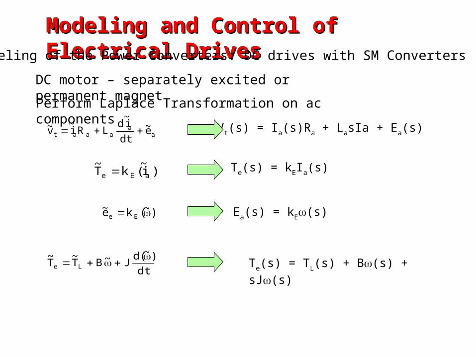
Perform Laplace Transformation on ac components
aa
aaat e~dti~
dLRi
~v~
)i~(kT
~aEe
)~(ke~ Ee
dt)~(d
J~BT~
T~
Le
Vt(s) = Ia(s)Ra + LasIa + Ea(s)
Te(s) = kEIa(s)
Ea(s) = kE(s)
Te(s) = TL(s) + B(s) + sJ(s)
DC motor – separately excited or permanent magnet
Modeling and Control of Electrical DrivesModeling and Control of Electrical DrivesModeling of the Power Converters: DC drives with SM Converters
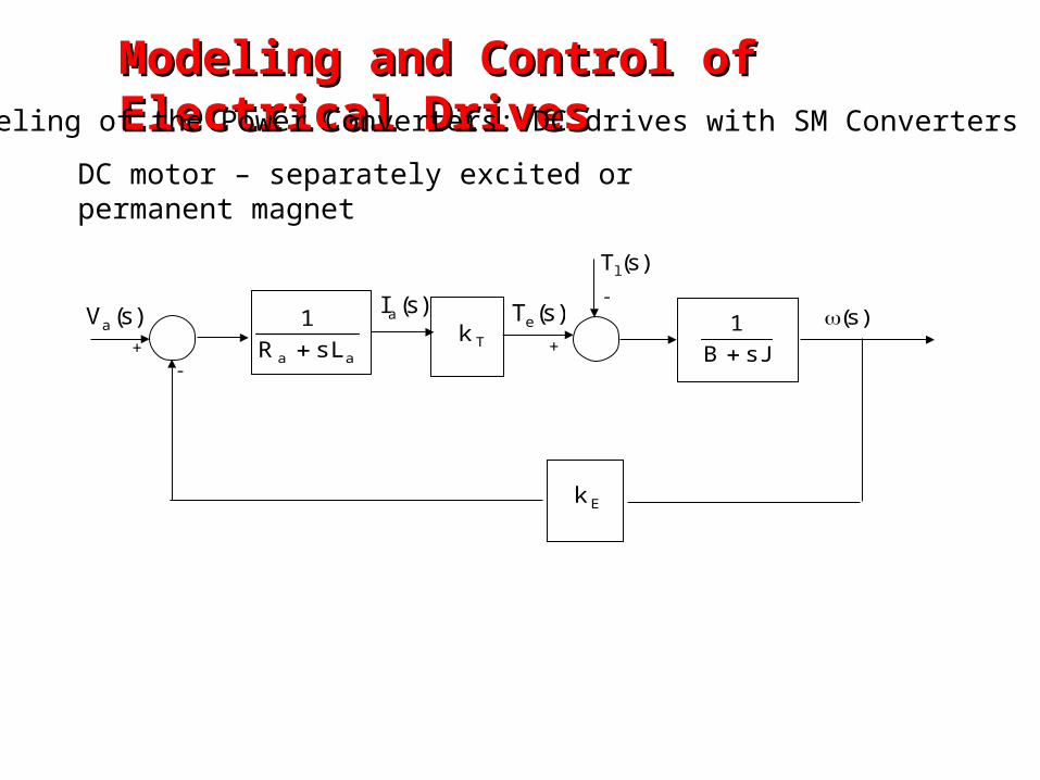
Tkaa sLR
1
)s(Tl
)s(Te
sJB1
Ek
)s(Ia )s()s(Va
+-
-
+
DC motor – separately excited or permanent magnet
Modeling and Control of Electrical DrivesModeling and Control of Electrical DrivesModeling of the Power Converters: DC drives with SM Converters
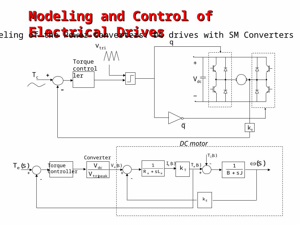
Tc
vtri
+
Vdc
−
q
q
+
–
kt
Torque controller
Tkaa sLR
1
)s(Tl
)s(Te
sJB1
Ek
)s(Ia )s()s(Va
+-
-
+
Torquecontroller
Converter
peak,tri
dc
VV)s(Te
-+
DC motor
Modeling and Control of Electrical DrivesModeling and Control of Electrical DrivesModeling of the Power Converters: DC drives with SM Converters
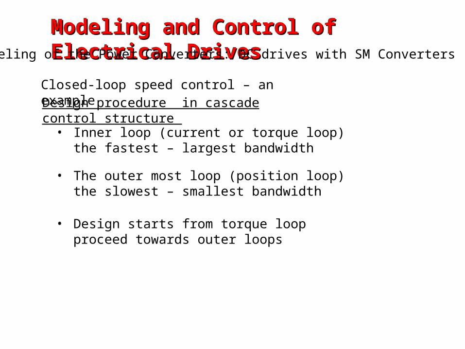
Design procedure in cascade control structure
• Inner loop (current or torque loop) the fastest – largest bandwidth
• The outer most loop (position loop) the slowest – smallest bandwidth
• Design starts from torque loop proceed towards outer loops
Closed-loop speed control – an example
Modeling and Control of Electrical DrivesModeling and Control of Electrical DrivesModeling of the Power Converters: DC drives with SM Converters
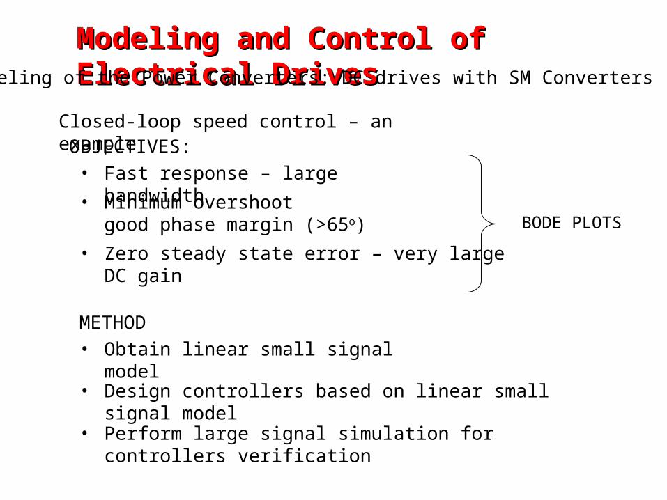
OBJECTIVES:• Fast response – large bandwidth
• Minimum overshoot good phase margin (>65o)
• Zero steady state error – very large DC gain
BODE PLOTS
• Obtain linear small signal model
METHOD
• Design controllers based on linear small signal model
• Perform large signal simulation for controllers verification
Closed-loop speed control – an example
Modeling and Control of Electrical DrivesModeling and Control of Electrical DrivesModeling of the Power Converters: DC drives with SM Converters
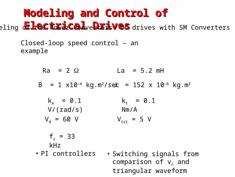
Ra = 2 La = 5.2 mH
J = 152 x 10–6 kg.m2B = 1 x10⁻⁴ kg.m2/sec
kt = 0.1 Nm/Ake = 0.1 V/(rad/s)
Vd = 60 V Vtri = 5 V
fs = 33 kHz
Closed-loop speed control – an example
• PI controllers • Switching signals from comparison of vc and triangular waveform
Modeling and Control of Electrical DrivesModeling and Control of Electrical DrivesModeling of the Power Converters: DC drives with SM Converters
Bode Diagram
Frequency (rad/sec)
-50
0
50
100
150From: Input Point To: Output Point
Mag
nitu
de (
dB)
10-2
10-1
100
101
102
103
104
105
-90
-45
0
45
90
Pha
se (
deg)
compensated
compensated
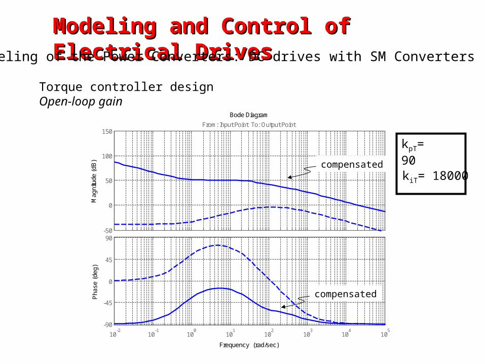
kpT= 90
kiT= 18000
Modeling and Control of Electrical DrivesModeling and Control of Electrical DrivesModeling of the Power Converters: DC drives with SM Converters
Torque controller design Open-loop gain
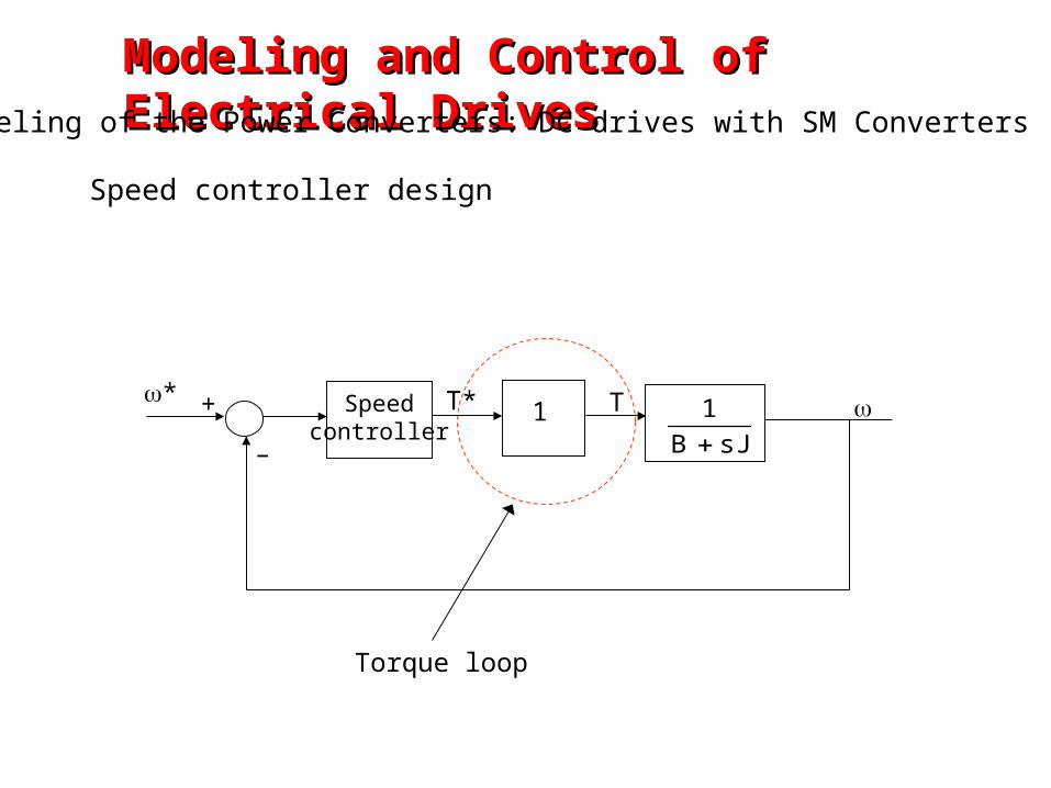
Speed controller design
1Speedcontroller sJB
1
* T* T
–
+
Torque loop
Modeling and Control of Electrical DrivesModeling and Control of Electrical DrivesModeling of the Power Converters: DC drives with SM Converters
Bode Diagram
Frequency (Hz)
-50
0
50
100
150From: Input Point To: Output Point
Mag
nitu
de (
dB)
10-2
10-1
100
101
102
103
104
-180
-135
-90
-45
0
Pha
se (
deg)
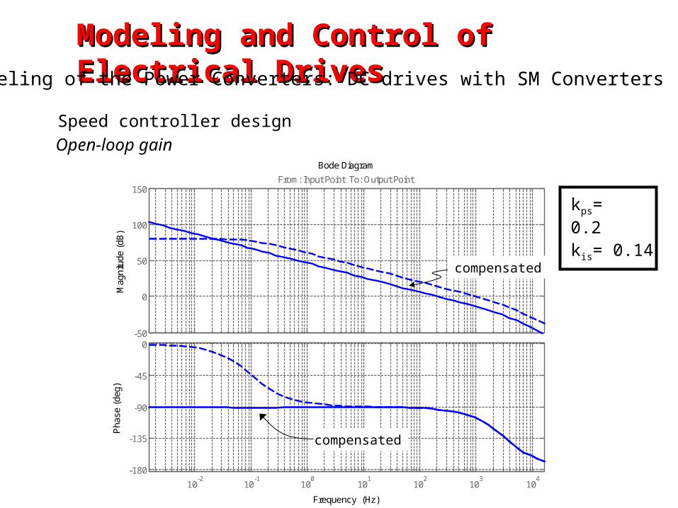
Open-loop gain
compensated
kps= 0.2
kis= 0.14
compensated
Speed controller design
Modeling and Control of Electrical DrivesModeling and Control of Electrical DrivesModeling of the Power Converters: DC drives with SM Converters
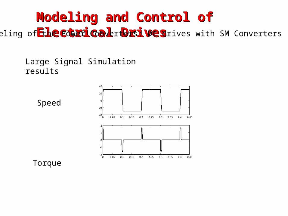
Large Signal Simulation results
0 0.05 0.1 0.15 0.2 0.25 0.3 0.35 0.4 0.45-40
-20
0
20
40
0 0.05 0.1 0.15 0.2 0.25 0.3 0.35 0.4 0.45-2
-1
0
1
2
Speed
Torque
Modeling and Control of Electrical DrivesModeling and Control of Electrical DrivesModeling of the Power Converters: DC drives with SM Converters
Modeling and Control of Electrical DrivesModeling and Control of Electrical DrivesModeling of the Power Converters: IM drives
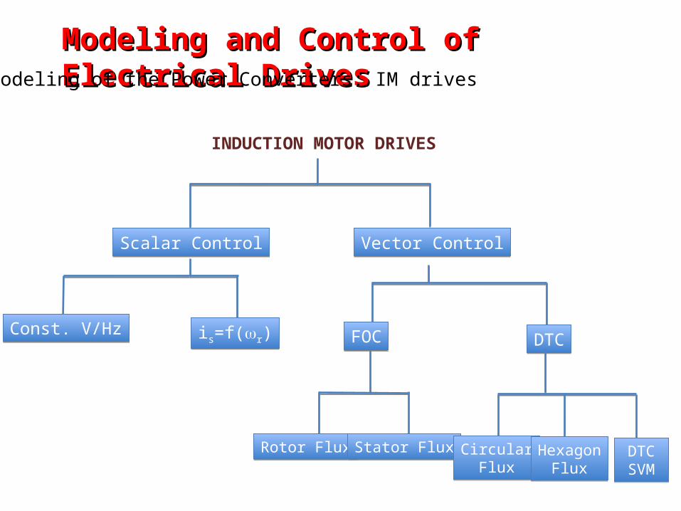
INDUCTION MOTOR DRIVES
Scalar ControlScalar Control Vector ControlVector Control
Const. V/HzConst. V/Hz is=f(r)is=f(r) FOCFOC DTCDTC
Rotor FluxRotor Flux Stator FluxStator Flux CircularFlux
CircularFlux
HexagonFlux
HexagonFlux
DTCSVMDTCSVM
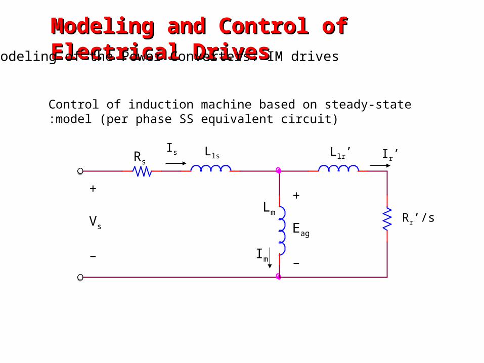
Control of induction machine based on steady-state model (per phase SS equivalent circuit):
Rr’/s
+
Vs
–
RsLls Llr’
+
Eag
–
Is Ir’
Im
Lm
Modeling and Control of Electrical DrivesModeling and Control of Electrical DrivesModeling of the Power Converters: IM drives
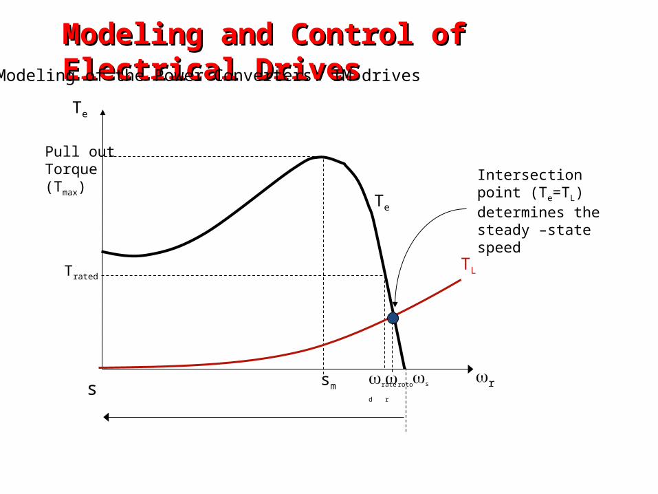
rs
Trated
Pull out Torque(Tmax)
Te
ssm ratedrotor
TL
Te
Intersection point (Te=TL) determines the steady –state speed
Modeling and Control of Electrical DrivesModeling and Control of Electrical DrivesModeling of the Power Converters: IM drives
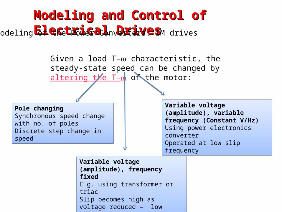
Given a load T– characteristic, the steady-state speed can be changed by altering the T– of the motor:
Pole changing Synchronous speed change with no. of polesDiscrete step change in speed
Pole changing Synchronous speed change with no. of polesDiscrete step change in speed
Variable voltage (amplitude), frequency fixedE.g. using transformer or triacSlip becomes high as voltage reduced – low efficiency
Variable voltage (amplitude), frequency fixedE.g. using transformer or triacSlip becomes high as voltage reduced – low efficiency
Variable voltage (amplitude), variable frequency (Constant V/Hz)Using power electronics converter Operated at low slip frequency
Variable voltage (amplitude), variable frequency (Constant V/Hz)Using power electronics converter Operated at low slip frequency
Modeling and Control of Electrical DrivesModeling and Control of Electrical DrivesModeling of the Power Converters: IM drives
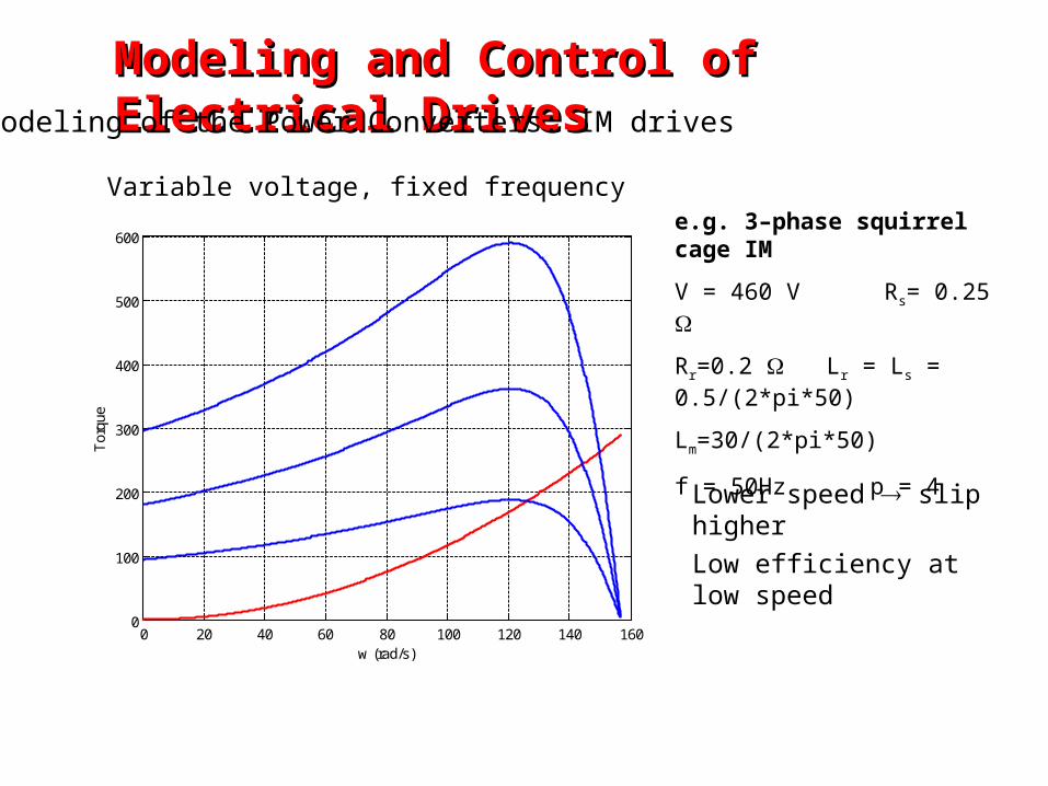
Variable voltage, fixed frequency
0 20 40 60 80 100 120 140 1600
100
200
300
400
500
600
Tor
que
w (rad/s)
Lower speed slip higher
Low efficiency at low speed
e.g. 3–phase squirrel cage IM
V = 460 V Rs= 0.25
Rr=0.2 Lr = Ls = 0.5/(2*pi*50)
Lm=30/(2*pi*50)
f = 50Hz p = 4
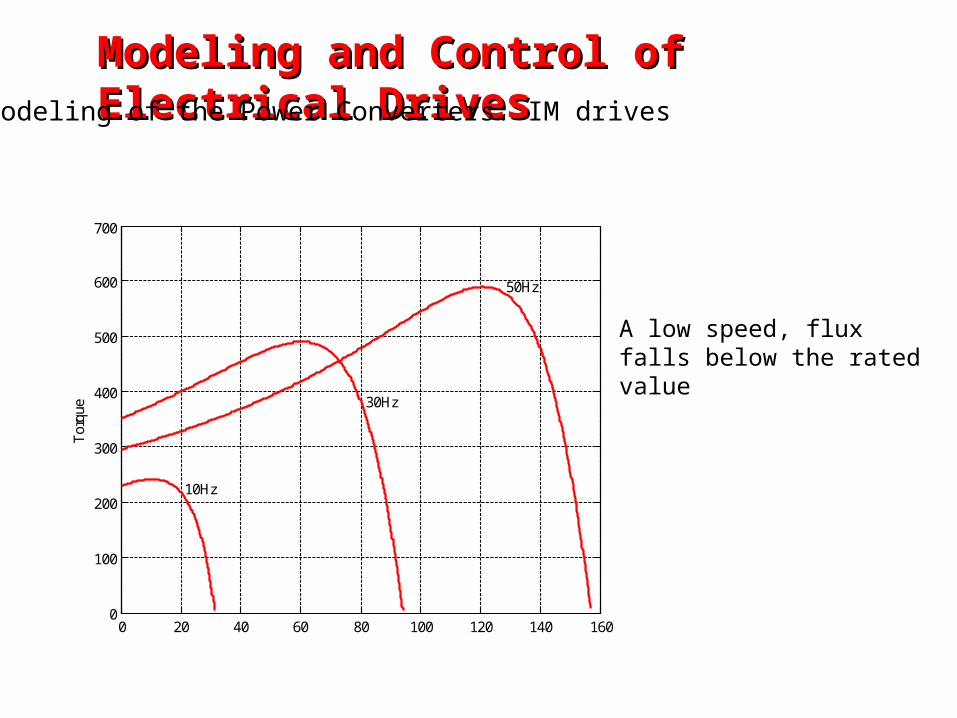
Modeling and Control of Electrical DrivesModeling and Control of Electrical DrivesModeling of the Power Converters: IM drives
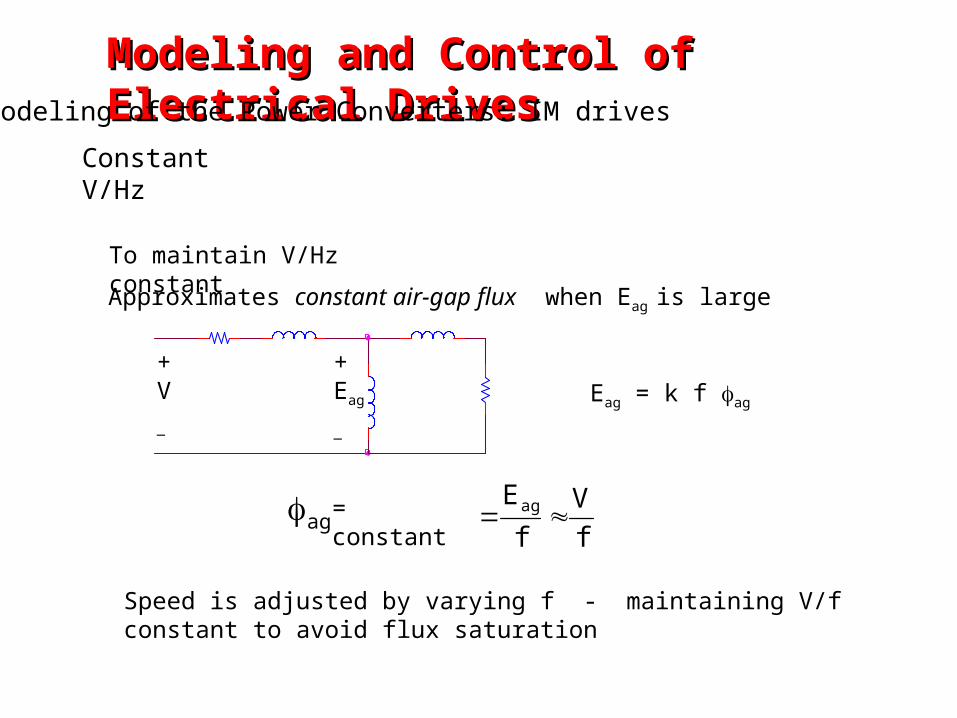
Constant V/Hz
Approximates constant air-gap flux when Eag is large
Eag = k f ag
f
V
f
Eag ag = constant
Speed is adjusted by varying f - maintaining V/f constant to avoid flux saturation
To maintain V/Hz constant
+V
_
+Eag
_
Modeling and Control of Electrical DrivesModeling and Control of Electrical DrivesModeling of the Power Converters: IM drives
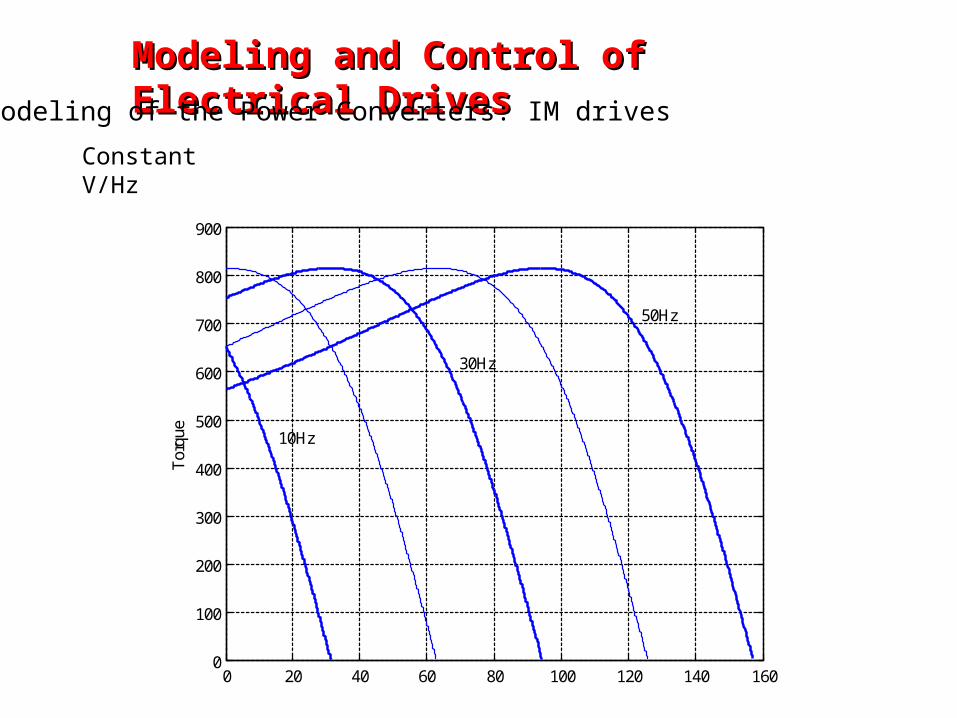
0 20 40 60 80 100 120 140 1600
100
200
300
400
500
600
700
800
900
Tor
que
50Hz
30Hz
10Hz
Modeling and Control of Electrical DrivesModeling and Control of Electrical Drives
Modeling of the Power Converters: IM drives
Constant V/Hz
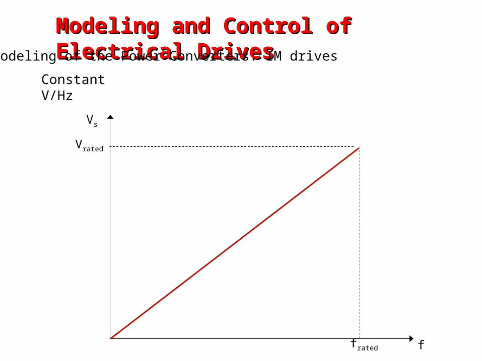
Vrated
frated
Vs
f
Modeling and Control of Electrical DrivesModeling and Control of Electrical DrivesModeling of the Power Converters: IM drives
Constant V/Hz
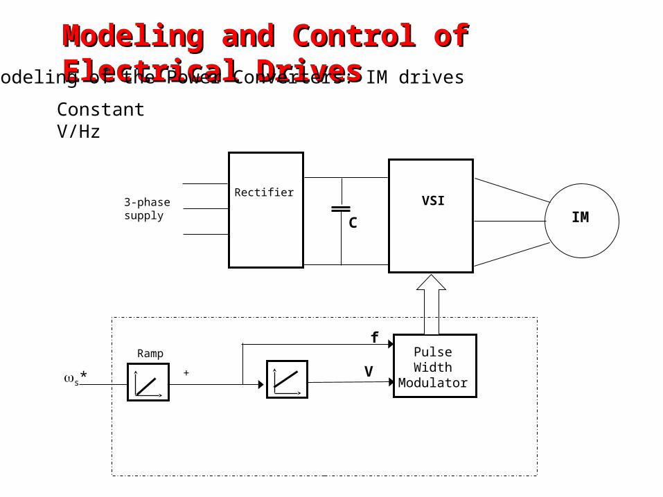
VSIRectifier
3-phase supply IM
Pulse Width
Modulators*+
Rampf
C
V
Modeling and Control of Electrical DrivesModeling and Control of Electrical DrivesModeling of the Power Converters: IM drives
Constant V/Hz
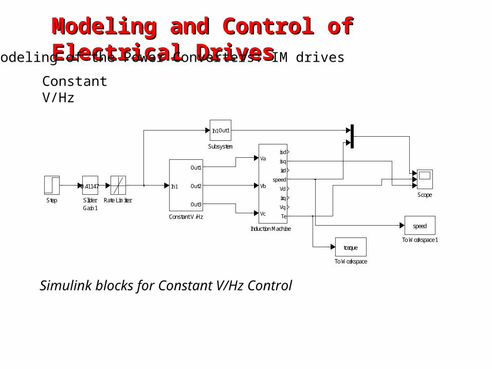
Modeling and Control of Electrical DrivesModeling and Control of Electrical DrivesModeling of the Power Converters: IM drives
To Workspace1
speed
To Workspace
torque
Subsystem
In1Out1
Step SliderGain1
0.41147Scope
Rate Limiter
Induction Machine
Va
Vb
Vc
isd
isq
ird
speed
Vd
irq
Vq
TeConstant V/Hz
In1
Out1
Out2
Out3
Constant V/Hz
Simulink blocks for Constant V/Hz Control
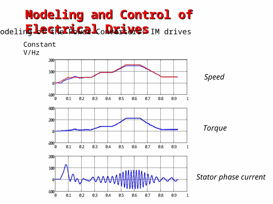
Modeling and Control of Electrical DrivesModeling and Control of Electrical DrivesModeling of the Power Converters: IM drives
0 0.1 0.2 0.3 0.4 0.5 0.6 0.7 0.8 0.9 1-100
0
100
200
0 0.1 0.2 0.3 0.4 0.5 0.6 0.7 0.8 0.9 1-200
0
200
400
0 0.1 0.2 0.3 0.4 0.5 0.6 0.7 0.8 0.9 1-100
0
100
200
Constant V/Hz
Speed
Torque
Stator phase current
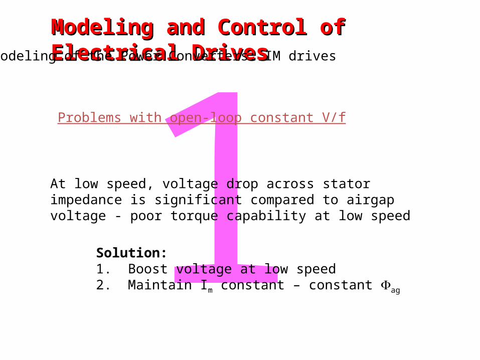
1Problems with open-loop constant V/f
At low speed, voltage drop across stator impedance is significant compared to airgap voltage - poor torque capability at low speed
Solution:1. Boost voltage at low speed2. Maintain Im constant – constant ag
Modeling and Control of Electrical DrivesModeling and Control of Electrical DrivesModeling of the Power Converters: IM drives
Modeling and Control of Electrical DrivesModeling and Control of Electrical DrivesModeling of the Power Converters: IM drives
0 20 40 60 80 100 120 140 1600
100
200
300
400
500
600
700
Tor
que
50Hz
30Hz
10Hz
A low speed, flux falls below the rated value
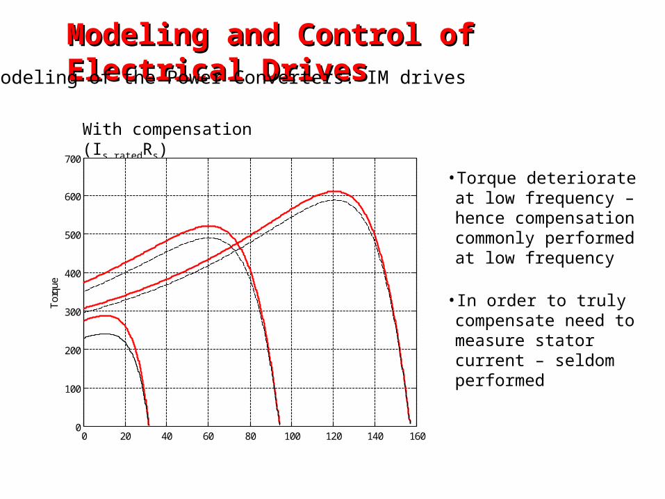
With compensation (Is,ratedRs)
0 20 40 60 80 100 120 140 1600
100
200
300
400
500
600
700
Tor
que
• Torque deteriorate at low frequency – hence compensation commonly performed at low frequency
• In order to truly compensate need to measure stator current – seldom performed
Modeling and Control of Electrical DrivesModeling and Control of Electrical DrivesModeling of the Power Converters: IM drives
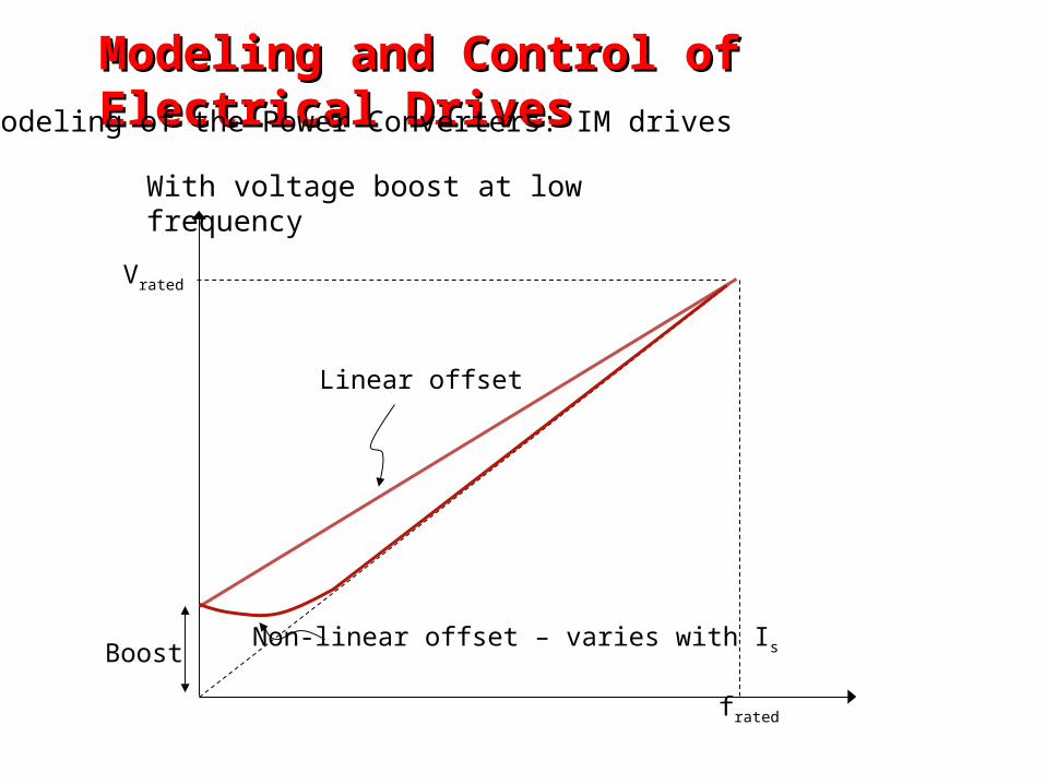
With voltage boost at low frequency
Vrated
frated
Linear offset
Non-linear offset – varies with IsBoost
Modeling and Control of Electrical DrivesModeling and Control of Electrical DrivesModeling of the Power Converters: IM drives
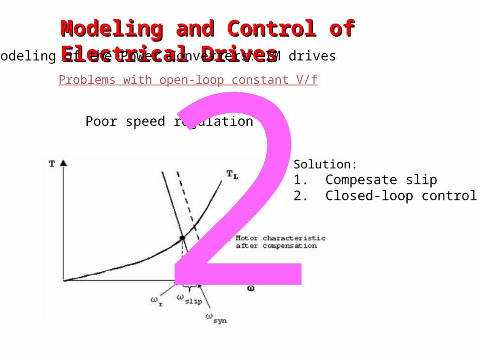
Poor speed regulation
Solution:1. Compesate slip2. Closed-loop control
Problems with open-loop constant V/f
2Modeling and Control of Electrical DrivesModeling and Control of Electrical Drives
Modeling of the Power Converters: IM drives
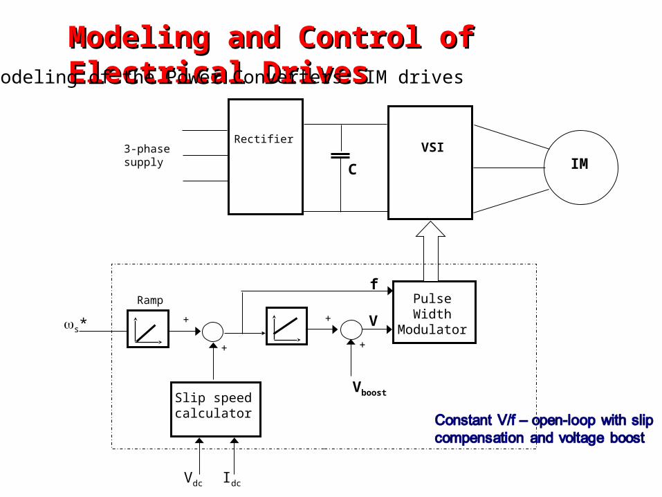
VSIRectifier
3-phase supply IM
Pulse Width
Modulator
VboostSlip speed calculator
s*++
++ V
Vdc Idc
Rampf
C
Modeling and Control of Electrical DrivesModeling and Control of Electrical DrivesModeling of the Power Converters: IM drives
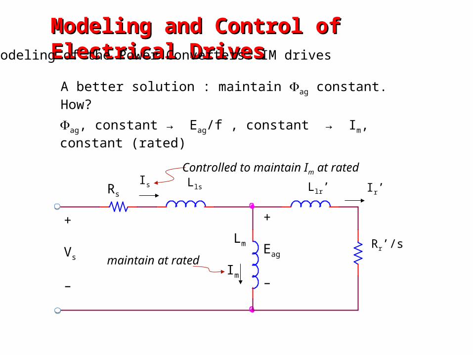
A better solution : maintain ag constant. How?
ag, constant → Eag/f , constant → Im, constant (rated)
maintain at rated
Controlled to maintain Im at rated
Modeling and Control of Electrical DrivesModeling and Control of Electrical DrivesModeling of the Power Converters: IM drives
Rr’/s
+
Vs
–
RsLls Llr’
+
Eag
–
Is Ir’
Im
Lm
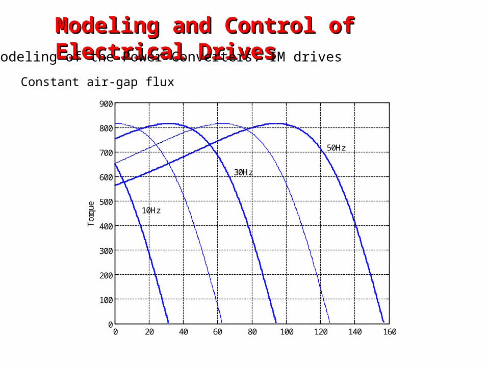
0 20 40 60 80 100 120 140 1600
100
200
300
400
500
600
700
800
900
Tor
que
50Hz
30Hz
10Hz
Modeling and Control of Electrical DrivesModeling and Control of Electrical DrivesModeling of the Power Converters: IM drives
Constant air-gap flux
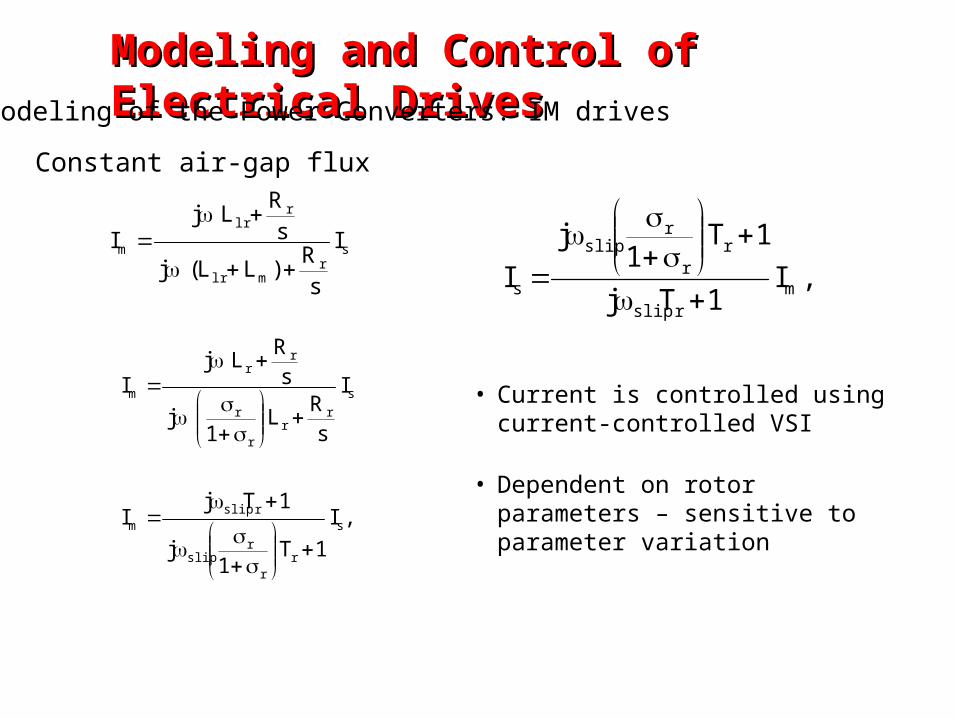
sr
mlr
rlr
m I
sR
)LL(j
sR
LjI
,I
1T1
j
1TjI
I
sR
L1
j
sR
LjI
s
rr
rslip
rslipm
s
rr
r
r
rr
m
,I1Tj
1T1
j
I mrslip
rr
rslip
s
• Current is controlled using current-controlled VSI
• Dependent on rotor parameters – sensitive to parameter variation
Modeling and Control of Electrical DrivesModeling and Control of Electrical DrivesModeling of the Power Converters: IM drives
Constant air-gap flux
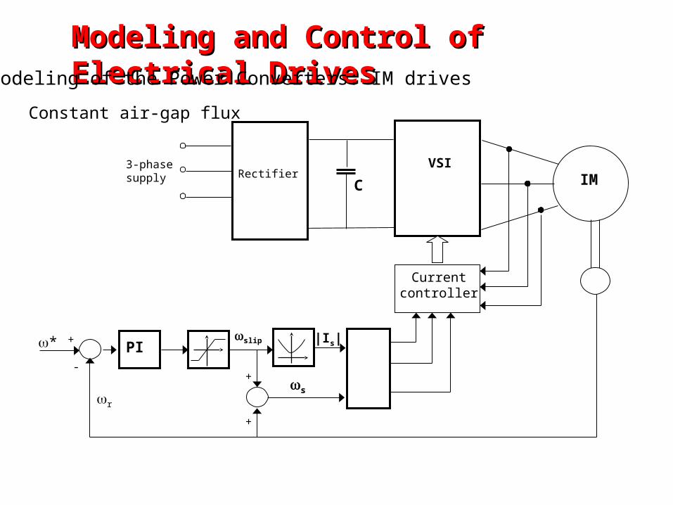
VSIRectifier
3-phase supply IM
*
+
+ |Is|slip
C
Current controller
s
PI
+
r
-
Modeling and Control of Electrical DrivesModeling and Control of Electrical DrivesModeling of the Power Converters: IM drives
Constant air-gap flux

THANK YOUTHANK YOU