protecting distribution substation assets – modern ... pape… · 1 protecting distribution...
TRANSCRIPT

Protecting Distribution Substation Assets – Modern Protection Schemes With
Microprocessor-Based Relays
Lee Ayers Mid-Carolina Electric Cooperative
Mark Lanier Atlantic Power Sales, LLC
Larry Wright Schweitzer Engineering Laboratories, Inc.
© 2013 IEEE. Personal use of this material is permitted. Permission from IEEE must be obtained for all other uses, in any current or future media, including reprinting/republishing this material for advertising or promotional purposes, creating new collective works, for resale or redistribution to servers or lists, or reuse of any copyrighted component of this work in other works.
This paper was presented at the 66th Annual Conference for Protective Relay Engineers and can be accessed at: http://dx.doi.org/10.1109/CPRE.2013.6822033.
For the complete history of this paper, refer to the next page.

Presented at the 66th Annual Conference for Protective Relay Engineers
College Station, Texas April 8–11, 2013
Previously presented at the 66th Annual Georgia Tech Protective Relaying Conference, April 2012
Originally presented at the 11th Annual Clemson University Power Systems Conference, March 2012

1
Protecting Distribution Substation Assets –Modern Protection Schemes With
Microprocessor-Based Relays Lee Ayers, Mid-Carolina Electric Cooperative
Mark Lanier, Atlantic Power Sales, LLC Larry Wright, Schweitzer Engineering Laboratories, Inc.
Abstract—Distribution substations at electric cooperatives and municipal utilities have historically involved simple protection schemes consisting of feeder circuit overcurrent, reclosing, and transformer protection, either with high-side fuses or differential and overcurrent protection. These protective devices have served to protect the transmission operator as much or more than the distribution substation.
Modern microprocessor-based relays allow for much better protection schemes to protect the distribution substation assets. This paper analyzes several schemes that have recently been implemented at Mid-Carolina Electric Cooperative in South Carolina. Benefits include:
• Faster tripping times—all zones in the substation are protected with differential relays. − Reduced arc-flash hazards for personnel. − Reduced equipment damage during faults.
• Backup protection schemes for each piece of equipment in the substation. − Backup feeder protection via transformer differential
relays. − Detection of failed feeder relay and failed feeder
breaker trip coil. − Backup bus differential via transformer differential
low-side overcurrent. − Redundant transformer differential relays, one of
which also includes the bus in the differential zone. • Superior fault analysis through satellite clock time
synchronization to all substation relays. • Communications to each relay via an Ethernet network
that provides both SCADA communications and engineering access for event retrieval.
I. INTRODUCTION Distribution substations at electric cooperatives and
municipal utilities have historically involved simple protection schemes consisting of feeder circuit overcurrent, reclosing, and transformer protection, either with high-side fuses or differential and overcurrent relays. Modern microprocessor-based relays allow for much better protection schemes to protect the distribution substation assets.
Mid-Carolina Electric Cooperative (MCEC) is a not-for-profit electric distribution utility headquartered in Lexington, South Carolina, that serves 52,000 member-owners who reside in Lexington, Richland, Newberry, Saluda, and Aiken Counties. Over the years, MCEC has updated their protection schemes as load increased and new technologies became available. This paper analyzes protection schemes that have been implemented at MCEC over the years, including their latest microprocessor-based scheme. This latest scheme provides benefits, including faster tripping times, backup protection, superior fault analysis, and Ethernet communications.
II. HISTORY AT MID-CAROLINA ELECTRIC COOPERATIVE Early MCEC distribution substation protection packages, in
their simplest form, consisted of three power fuses on the high side of a delta/wye transformer and hydraulic reclosers on the outgoing feeders. As transformer size increased, the power fuses were replaced with a transformer relay package consisting of three electromechanical differential relays and four electromechanical overcurrent relays. The differential relays protected only the power transformer. The overcurrent relays were applied with three time-overcurrent and/or instantaneous overcurrent elements connected to the H1, H2, and H3 transformer bushing current transformers (BCTs) and one time element connected to the X0 transformer BCT. This arrangement protected the transformer but only provided slow ground fault protection for the low-voltage bus. The bus protection was minimal because of the delta/wye-grounded connection of the power transformer—because most of the low-side faults were line to ground, they could not easily be detected by high-side overcurrent relays. This scheme did not provide reliable target information, nor did it have event records available.

2
Hydraulic reclosers were later replaced with three-phase electronic reclosers. These reclosers were typically configured in a tandem disconnect/bypass switch arrangement, with the bypass switch directly connected to the main low-side bus (Fig. 1 and Fig. 2). Some bypass switches were fused; others had solid blades. Both configurations did not provide adequate protection when bypassed. Solid blade bypass switches provided no fault protection for the feeder circuit, especially for ground faults, which could not be easily detected by the transformer high-side overcurrent relays. Fused bypass switches provided fault protection for the feeder circuit but were a personnel hazard for workers underneath the fuses during maintenance activities.
Fig. 1. Bypass Switch Arrangement
R R R
79
50/51N
50/51
79
50/51N
50/51
79
50/51N
50/51
51 51N
87
R = Recloser
Fig. 2. Bypass Switch One-Line Diagram
III. MORE RECENT APPLICATIONS About 1990, as loading increased and with the advent of
microprocessor-based relays, electronic reclosers gave way to circuit breakers with reclosing electronic relays. These were applied to the substation through a main and transfer bus scheme that provided uncompromised protection during the clearance of a single feeder breaker (Fig. 3 and Fig. 4). This in itself enhanced personnel safety and improved protection by being able to clear the breaker without bypassing the feeder directly to the main bus, as in the previous arrangement.
Fig. 3. Main and Transfer Bus Arrangement
Fig. 4. Main and Transfer Bus One-Line Diagram

3
The electromechanical relays shown in Fig. 4 also began to be replaced by microprocessor-based relays. The transformer differential relay was replaced by a transformer management relay, as shown in Fig. 5. The transformer management relay allowed the elimination of the four overcurrent relays because each winding of the relay also had overcurrent elements, among the many other available functions. The high-side winding phase time-overcurrent element was enabled to emulate the electromechanical overcurrent functions. A high-side residual ground time-overcurrent element was also enabled as additional protection for the delta winding of the transformer. The low-side winding phase and neutral ground time-overcurrent elements were enabled and coordinated to act as a backup relay in case of a feeder breaker relay failure. There was also a separate three-phase microprocessor-based overcurrent relay applied for transformer backup protection.
IV. WHY CHANGE NOW? The three-winding transformer management relay scheme
has worked well for enhancing protection as well as personnel safety but has not been without minor problems of its own. One problem is the lack of time synchronization of the event records of the relays, making it difficult to time-align and analyze events. Also, there is no communication between the
relays and no communication back to the office due to differing communications protocols and relay asset management software. Retrieving event records is a manual process at the substation, using more than one software package.
The relay failure backup scheme has a minor flaw as well. The Winding 2 overcurrent element sees only a summation of the feeder currents (Fig. 5). This creates a problem when a single feeder fault involves more than one circuit fed from this winding, a common occurrence when two circuits share the same right of way. The transformer impedance limits the total fault current available. This maximum available fault current is then split across two or more feeder breakers, but the entire fault current is seen by the Winding 2 overcurrent element. The time coordination for detecting a failed feeder relay assumes that the current the Winding 2 overcurrent element sees is being fed through a single failed feeder relay. Thus the Winding 2 overcurrent element clears the low-side bus, the only thing that it can do, when only the two feeder breakers should clear. This is overcome in the new design with the relays directly communicating with each other.
Another minor problem with this scheme is accurately determining where the fault is located within the differential zone if it is not a visible external fault.
Fig. 5. Three-Winding Transformer Management Relay Scheme
4
51N
27/59
51
87
50/51N
7950/51
50/51N 7950/
5150/51N 7950/
5150/51N
Main Bus 1 Normally Open
Main Bus 2
Feeder 3 Feeder 2 Feeder 1
Transfer Bus 2
51 51
50/51N
51
50/51N
REF 51N 5151/51N 87
REF 50/51
Circuit Switcher
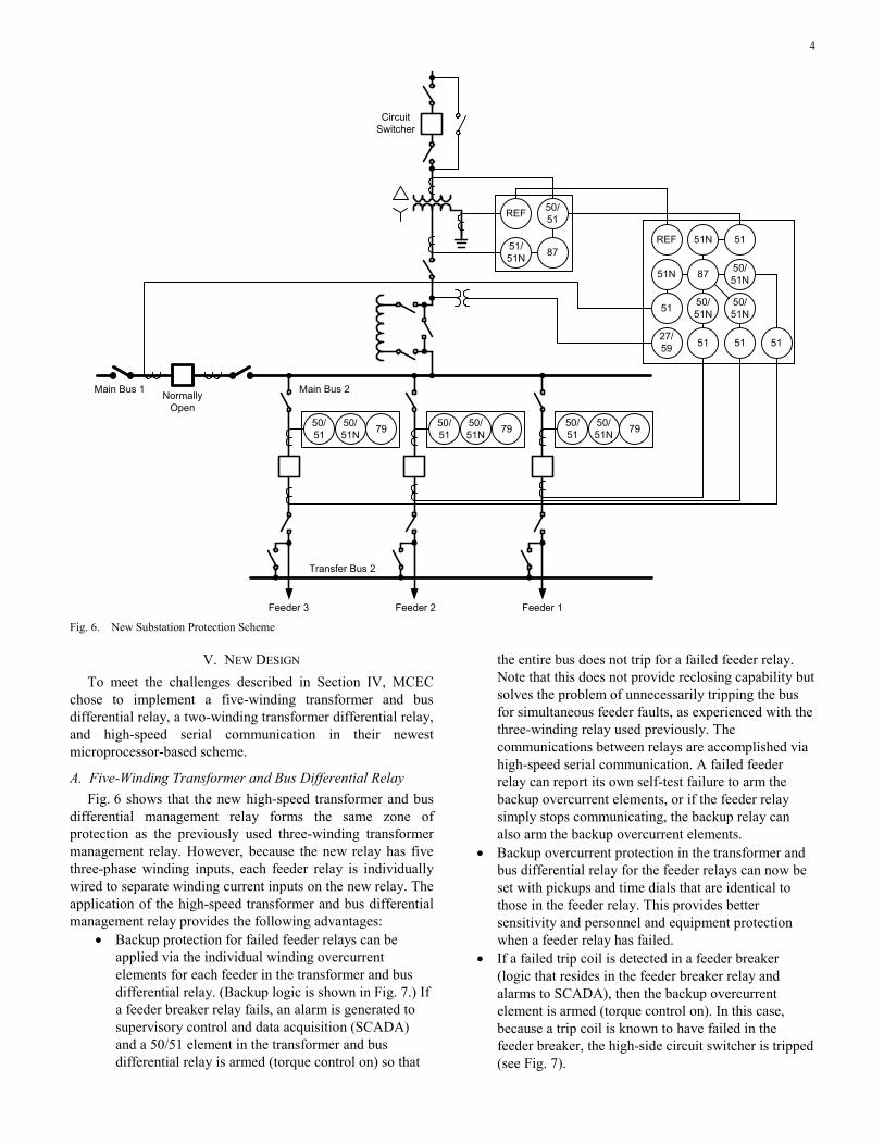
Fig. 6. New Substation Protection Scheme
V. NEW DESIGN To meet the challenges described in Section IV, MCEC
chose to implement a five-winding transformer and bus differential relay, a two-winding transformer differential relay, and high-speed serial communication in their newest microprocessor-based scheme.
A. Five-Winding Transformer and Bus Differential Relay Fig. 6 shows that the new high-speed transformer and bus
differential management relay forms the same zone of protection as the previously used three-winding transformer management relay. However, because the new relay has five three-phase winding inputs, each feeder relay is individually wired to separate winding current inputs on the new relay. The application of the high-speed transformer and bus differential management relay provides the following advantages:
• Backup protection for failed feeder relays can be applied via the individual winding overcurrent elements for each feeder in the transformer and bus differential relay. (Backup logic is shown in Fig. 7.) If a feeder breaker relay fails, an alarm is generated to supervisory control and data acquisition (SCADA) and a 50/51 element in the transformer and bus differential relay is armed (torque control on) so that
the entire bus does not trip for a failed feeder relay. Note that this does not provide reclosing capability but solves the problem of unnecessarily tripping the bus for simultaneous feeder faults, as experienced with the three-winding relay used previously. The communications between relays are accomplished via high-speed serial communication. A failed feeder relay can report its own self-test failure to arm the backup overcurrent elements, or if the feeder relay simply stops communicating, the backup relay can also arm the backup overcurrent elements.
• Backup overcurrent protection in the transformer and bus differential relay for the feeder relays can now be set with pickups and time dials that are identical to those in the feeder relay. This provides better sensitivity and personnel and equipment protection when a feeder relay has failed.
• If a failed trip coil is detected in a feeder breaker (logic that resides in the feeder breaker relay and alarms to SCADA), then the backup overcurrent element is armed (torque control on). In this case, because a trip coil is known to have failed in the feeder breaker, the high-side circuit switcher is tripped (see Fig. 7).

5
• A breaker failure (BF) timer and logic are built into the transformer and bus differential relay based on a BF initiate signal received from the feeder relay over high-speed serial communication. If the BF timer expires, then a retrip is issued to the feeder breaker. This ensures that the failure to trip is a breaker problem and not a failed output contact on the feeder breaker relay. If the breaker still fails to trip, then the high-side circuit switcher is tripped after a second time delay of 10 cycles (see Fig. 7).
• Restricted earth fault (REF) protection is available in the new relay and is applied for enhanced protection for the transformer wye winding. Also known as directional ground (67G) or zero-sequence neutral differential (87N) protection, REF protection uses ground current in the transformer neutral as a polarizing reference and zero-sequence current derived from the calculated residual current (IG or 3I0) as its operating quantity to detect single-line-to-ground faults in the transformer wye winding. The method is very secure, selective, fast, and easy to set as compared with transformer neutral overcurrent relays. The REF element provides fast tripping for ground faults within the transformer secondary below the pickup of the differential element. REF protection is much faster than traditional neutral time-overcurrent protection because coordination with downstream devices is not a concern. Because the low-side winding inputs extend to the feeder breakers, the REF element also provides backup protection for ground faults on the bus and bus regulators. If the normally open tie breaker is closed, REF is still in service to protect the in-service transformer and bus up to and including the tie breaker. If the five-winding transformer and bus differential relay on the transformer taken out of service is disabled or blocked, then the tie breaker (51N) element provides bus ground fault protection to the main bus normally protected by REF on the out-of-service relay.
• The new relay also allows for a three-phase voltage input from the low-side bus potentials. The relay is programmed with voltage elements to detect an open conductor on the transformer high side and open the high-side circuit switcher to prevent severely unbalanced voltages from being delivered to the customer. This trip is applied with a 60-second delay to ride through any system disturbances.
• Event reporting out of the new relay provides capability similar to a digital fault recorder because all bus currents and voltages are wired individually to the relay. These event reports can be collected locally at the relay or through the Ethernet connection to the relay. The Ethernet connection is used for both SCADA (DNP3 LAN/WAN) and remote engineering access.
• The new relay typically has differential tripping speeds of less than a cycle. This is a considerable improvement in tripping speed from prior relaying and provides better equipment and personnel protection.
Fig. 7. Transformer and Bus Differential Feeder Backup Logic
B. Two-Winding Transformer Differential Relay The backup transformer differential relay protects only the
transformer with current transformer (CT) inputs from the high- and low-side transformer BCTs (Fig. 4). The advantage of this scheme is that it can quickly determine if a substation trip is located in the transformer or elsewhere in the buswork, bypass switches, regulators, and so on. If the two-winding transformer relay and the five-winding transformer and bus differential relay both trip, the fault is expected to be within the transformer. If only the five-winding transformer and bus differential relay trips, the fault is unlikely to be in the transformer and other equipment can be inspected first to locate the fault.
The backup transformer differential relay also includes REF protection, which is applied for fast clearing of ground faults within the transformer wye winding. Again, if REF trips only on the transformer and bus differential relay, the fault is not expected to be in the transformer.
Finally, the backup transformer differential relay has 50/51 overcurrent elements applied on the high side for transformer protection and a 51 time-overcurrent element on the low side for bus overload protection. The 51 element on the low side sends a signal that the 51 element has timed out to the feeder relays via high-speed serial communication. If the feeder relays are timing to trip and this signal is received from the bus overload, the feeder relay is tripped. If the feeder relays do not trip, then the bus overcurrent element will trip the high-side circuit switcher after an 8-cycle delay. The delay allows for communications delay, breaker opening time, and overcurrent element reset of the bus overload 51 element.
6
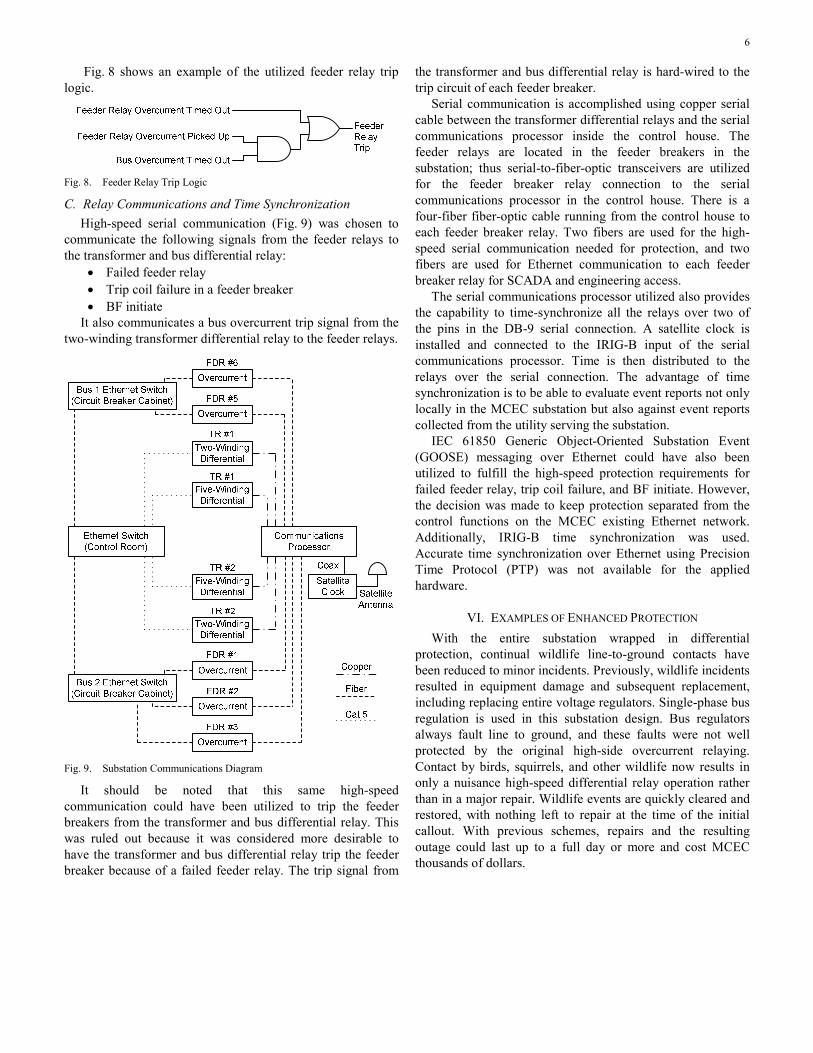
Fig. 8 shows an example of the utilized feeder relay trip logic.
Fig. 8. Feeder Relay Trip Logic
C. Relay Communications and Time Synchronization High-speed serial communication (Fig. 9) was chosen to
communicate the following signals from the feeder relays to the transformer and bus differential relay:
• Failed feeder relay • Trip coil failure in a feeder breaker • BF initiate
It also communicates a bus overcurrent trip signal from the two-winding transformer differential relay to the feeder relays.
Fig. 9. Substation Communications Diagram
It should be noted that this same high-speed communication could have been utilized to trip the feeder breakers from the transformer and bus differential relay. This was ruled out because it was considered more desirable to have the transformer and bus differential relay trip the feeder breaker because of a failed feeder relay. The trip signal from
the transformer and bus differential relay is hard-wired to the trip circuit of each feeder breaker.
Serial communication is accomplished using copper serial cable between the transformer differential relays and the serial communications processor inside the control house. The feeder relays are located in the feeder breakers in the substation; thus serial-to-fiber-optic transceivers are utilized for the feeder breaker relay connection to the serial communications processor in the control house. There is a four-fiber fiber-optic cable running from the control house to each feeder breaker relay. Two fibers are used for the high-speed serial communication needed for protection, and two fibers are used for Ethernet communication to each feeder breaker relay for SCADA and engineering access.
The serial communications processor utilized also provides the capability to time-synchronize all the relays over two of the pins in the DB-9 serial connection. A satellite clock is installed and connected to the IRIG-B input of the serial communications processor. Time is then distributed to the relays over the serial connection. The advantage of time synchronization is to be able to evaluate event reports not only locally in the MCEC substation but also against event reports collected from the utility serving the substation.
IEC 61850 Generic Object-Oriented Substation Event (GOOSE) messaging over Ethernet could have also been utilized to fulfill the high-speed protection requirements for failed feeder relay, trip coil failure, and BF initiate. However, the decision was made to keep protection separated from the control functions on the MCEC existing Ethernet network. Additionally, IRIG-B time synchronization was used. Accurate time synchronization over Ethernet using Precision Time Protocol (PTP) was not available for the applied hardware.
VI. EXAMPLES OF ENHANCED PROTECTION With the entire substation wrapped in differential
protection, continual wildlife line-to-ground contacts have been reduced to minor incidents. Previously, wildlife incidents resulted in equipment damage and subsequent replacement, including replacing entire voltage regulators. Single-phase bus regulation is used in this substation design. Bus regulators always fault line to ground, and these faults were not well protected by the original high-side overcurrent relaying. Contact by birds, squirrels, and other wildlife now results in only a nuisance high-speed differential relay operation rather than in a major repair. Wildlife events are quickly cleared and restored, with nothing left to repair at the time of the initial callout. With previous schemes, repairs and the resulting outage could last up to a full day or more and cost MCEC thousands of dollars.

7
VII. EXAMPLE OF PERSONNEL SAFETY One example of personnel injury that was averted by
MCEC using the enhanced bus differential protection scheme shown in Fig. 5 occurred during routine voltage regulator exercising. The technician, per routine practice, manually stepped the regulator tap out of bandwidth limitations. The control was then returned to automatic to see that the control was working. During this routine testing, the regulator internal bridging reactor failed. The only things the technician noticed were a slight gurgle from within the regulator, the high-side breaker and feeder breakers tripping, and the eerie silence of a de-energized substation. Had this incident occurred with only high-side overcurrent protection, catastrophic failure of the regulator is likely to have occurred. This also could have resulted in serious injury to the technician standing in front of the regulator. The result with high-speed differential protection was no personnel injury and an easily repaired regulator.
VIII. CONCLUSION The implemented protection scheme provides high-speed
protection for the entire substation, which minimizes equipment damage for any fault and provides maximum personnel protection. Each piece of equipment now has a true backup protection device, as the following describes:
• Feeder relays are backed up by the transformer and bus differential overcurrent relay.
• Failed trip coils in the feeder breakers are detected and backed up by the transformer and bus differential overcurrent relay.
• Breaker failure is implemented for the feeder breakers in the transformer and bus differential relay.
• The low-voltage substation bus and bus regulators are protected primarily by the transformer and bus differential relay and backed up by the low-side overcurrent element in the two-winding transformer differential relay.
• Phase differential and REF are implemented in both differential relays.
It is expected that as more substations are upgraded and more experience is gained, standard reliability metrics will improve. As described above, the new features implemented should result in reduced durations of outages, thereby decreasing the System Average Interruption Duration Index (SAIDI). Also, because the new features should more accurately and consistently trip only the device feeding the fault, the System Average Interruption Frequency Index (SAIFI) is expected to decrease as well [1].
IX. REFERENCE [1] S. Yeddanapudi, “Distribution System Reliability Evaluation.”
Available: http://www.ee.iastate.edu/~jdm/ee653/DistributionReliability Predictive.ppt.
X. BIOGRAPHIES Lee Ayers received a BS in Electrical Engineering from Clemson University in 1982. From 1982 until 1986, he worked for Central Electric Power Cooperative in Columbia, South Carolina. Since 1986, he has been employed as System Engineer with Mid-Carolina Electric Cooperative in Lexington, South Carolina, managing substations, metering, system control and dispatch, and outside plant communications.
Mark Lanier, P.E., received a BS in Electrical Engineering in 1989 and an MBA in 2007 from the University of South Carolina. From 1989 to 2003, he designed coal- and gas-fired power plant electrical systems at Duke/Fluor Daniel, a subsidiary of Duke Energy. He left Duke Energy to join Schweitzer Engineering Laboratories, Inc. as a field application engineer, where he worked from 2004 to 2008, providing technical support for protective relaying products and customer training. Mark is presently a Managing Member of Atlantic Power Sales, LLC, and is a registered professional engineer in the state of South Carolina.
Larry Wright, P.E., received a BS in Electrical Engineering in 1982 from North Carolina State University. From 1982 until 2003, he worked for Duke Energy, designing nuclear, hydroelectric, and fossil-powered generating stations for Duke Energy and other utilities and independent power producers. From 2003 to 2005, Larry served as the subject matter expert on protective relaying for Duke Energy’s generating stations. He joined Devine Tarbell Associates in 2005 as Manager of Electrical Engineering, providing consulting services to the hydroelectric industry. In 2008, he joined Schweitzer Engineering Laboratories, Inc., where he is presently employed as a field application engineer. Larry is a registered professional engineer in the states of North and South Carolina.
Previously presented at the 2013 Texas A&M Conference for Protective Relay Engineers.
© 2013 IEEE – All rights reserved. 20130212 • TP6525-01