proposed interface document between bs6349… · proposed interface document between bs6349, the...
TRANSCRIPT

SECED 2015 Conference: Earthquake Risk and Engineering towards a Resilient World 9-10 July 2015, Cambridge UK
PROPOSED INTERFACE DOCUMENT BETWEEN BS6349, THE BRITISH MARITIME STANDARD, AND BSEN1998, THE EUROCODE
FOR EARTHQUAKE RESISTANT DESIGN
David Gordon Elliott Smith1 Abstract: The British maritime standard BS6349 is being updated to be compatible with the Eurocodes. Hitherto BS6349 has had no part considering the seismic situation and the document here discussed is the first attempt to define a set of provisions for earthquake resistant design consistent with the Eurocodes and in particular Eurocode 8 (EC8 hereafter). It is to be included in the current series of revisions to B6349 and is presented as an interface document between the two sets of Standards. This paper gives a brief introduction to the new provisions and presents aspects of the structural modelling, which is contained mainly in the bound-on Commentary. 1.0 Background 1.1 Introduction Whilst BS6349 is written for the design of maritime structures in the UK, it is used internationally as few countries have their own Standards for maritime engineering. It is normally used by UK engineers in designing maritime structures abroad. The scope covers all coastal structures, including floating structures and breakwaters. It is not written with offshore structures in mind, for which parts might be applicable. Offshore structure are predominantly for the Petroleum and Natural Gas industries, which have their own standards. The procedures specified in the proposed interface standard are intended to suit typical project design time scales and for maritime engineers, for whom earthquake resistant design is a new discipline but who need to ensure satisfactory performance in a specified event , in particular that ductile behaviour is obtained, though the seismic event for which it is designed may differ substantially from that which eventually occurs. For maritime structures there is often insufficient time for the seismic design parameters to be established for sites for which the information is not readily available, so best available information has to be employed. Furthermore it is only recently that the information available for the design of maritime structures is of sufficient accuracy to justify consideration of the vertical component of excitation sometimes required in analyses to EC8 (qv). The draft Standard:
• defines the scope and populates the main text and commentary, though it contains some provisional material highlighted in red.
• contains boxed information, which may be modified in the light of further studies or to accommodate Client specified requirements. Additional annexes may be included for particular applications, for example, if adopted for nuclear engineering, requirements may be added relating to structures bridging faults, a situation not addressed in the design of maritime structures on account of the far lower likelihood of this occurring than an earthquake.
Whilst the main purpose of the documents to interrelate BS6349 with EC8, the documents consulted where an independent view or alternative approach was considered desirable were PIANC 2001, RC Borg’s of the Rose School treatise on maritime engineering of 2007, OCDI 2009 and ASCE 61 2014. The secondary references used are numerous.
1 David GE Smith, Consultant with URS/AECOM, [email protected]

D G E SMITH
1.2 The Excitation The draft discuses the selection of the excitation, in particular the pga (peak ground acceleration) for a hard site. 2.0 Analysis 2.1 General Comments Most maritime structures require some form of Soil-Structure Interaction (SSI).Spectral analysis is presented as the general method, though the lateral force method is included with comments on when it should be avoided. There is, however, a role for pushover analysis and time history analyses, which are mentioned. In non-seismic design:
• SLS analysis is performed for determining deflection. • ULS analyses are performed with unfactored loading and the worst credible material
strengths and with factored loading and best estimate material properties. The seismic condition is estimated:
• under quasi-permanent loading and the unfactored seismic loading. • with material safety factors to represent degradation during an earthquake.
2.2 Spectral Analysis Spectral analysis is an elastic method of general applicability where liquefaction or high pore water pressures are absent, though if present it may be used, providing liquefiable materials are replaced by hydrodynamic forces, for which Equation E19 of EC8-5 is appropriate. The spectral methods entail separate analyses to determine the inertial effects and the effects from a static analysis of the seismic combination of the coincidental actions. The spectral analysis:
• employ, for piled structures, behaviour factors similar to those in EC8-2 (qv) and for retaining walls the r factors in Clause .3.2.2 of EC8-5,
• give the inertial forces and displacements, but deflections obtained from the analysis are multiplied by q2 or r2.
It is noted that, in the static analysis, quayside cranes on container berths are to be considered as permanent loads, as are container loads close to the sea wall. 2.3 Non-linear Time History Analysis In the design of structures of performance Grade S and A it will sometmes be deemed necessary to conduct time history analyses with nonlinear soil and structural properties, though when using nonlinear soil properties, the structure is normally modelled elastically. The selection of the time histories is beyond the scope of this document. For more rigorous SSI analyses, appropriate software should be used. The simplest approach for routine analysis is to adopt the Mohr model for the soil and the following load stages:
• Replicate with short term soil properties the construction phase in as many phases as to reasonably describe the construction history, taking into account kentledge or surcharge as appropriate.
• Convert to long term soil properties to give the consolidation. • Convert to short term soil properties and introduce seismic excitation.
3.0 Retaining Walls For retaining walls the approaches presented are:
• The Mononobe Okabe method (M-O method hereafter) as in EC8-5. • The spectral equivalent of the M-O method with comparable material densities. • The spectral approach using the bulk density of the soil and the full wet density of the
concrete
D G E SMITH
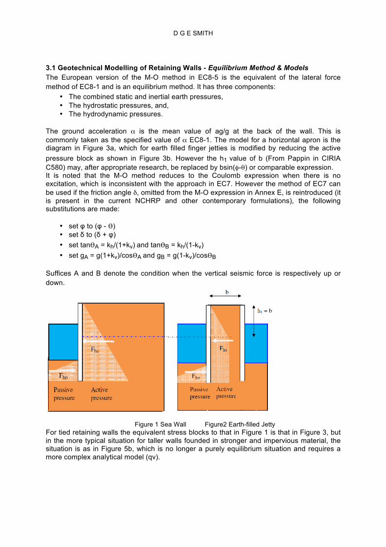
3.1 Geotechnical Modelling of Retaining Walls - Equilibrium Method & Models The European version of the M-O method in EC8-5 is the equivalent of the lateral force method of EC8-1 and is an equilibrium method. It has three components:
• The combined static and inertial earth pressures, • The hydrostatic pressures, and, • The hydrodynamic pressures.
The ground acceleration α is the mean value of ag/g at the back of the wall. This is commonly taken as the specified value of α EC8-1. The model for a horizontal apron is the diagram in Figure 3a, which for earth filled finger jetties is modified by reducing the active pressure block as shown in Figure 3b. However the h1 value of b (From Pappin in CIRIA C580) may, after appropriate research, be replaced by bsin(φ-θ) or comparable expression. It is noted that the M-O method reduces to the Coulomb expression when there is no excitation, which is inconsistent with the approach in EC7. However the method of EC7 can be used if the friction angle δ, omitted from the M-O expression in Annex E, is reintroduced (it is present in the current NCHRP and other contemporary formulations), the following substitutions are made:
• set φ to (φ - Ѳ) • set δ to (δ + φ) • set tanѲA = kh/(1+kv) and tanѲB = kh/(1-kv) • set gA = g(1+kv)/cosѲA and gB = g(1-kv)/cosѲB
Suffices A and B denote the condition when the vertical seismic force is respectively up or down.
Figure 1 Sea Wall Figure2 Earth-filled Jetty For tied retaining walls the equivalent stress blocks to that in Figure 1 is that in Figure 3, but in the more typical situation for taller walls founded in stronger and impervious material, the situation is as in Figure 5b, which is no longer a purely equilibrium situation and requires a more complex analytical model (qv).

D G E SMITH
Figure 3 : Sea Wall tied to Anchor Block Figure 4 : Sea Wall tied to Anchor Wall
(as for Container Berth) with Embedment (as for Sheet Piled Walls) Anchor walls normally have the same soil level both sides with the passive resistance of the soil in front and the non–seismic active pressures behind, as in Figure 3. The separation of the sea wall and anchor wall:
• needs to exceed that required for the non-seismic condition and the soil wedge model in the figures gives an indication of the separation at which full passive resistance of the anchor wall is to be expected.
• Where an existing sea wall is to be tied and there is a possibility of defective structure in places in the vicinity of the bed, an additional check should be made to improve the liklihood of survival of the anchor wall by ensuring the angle of repose of the soil, without the anchor, would not endanger the anchor wall. Such a measure can be expected to limit the propagation of the failure on either side of the failed section and facilitate the reinstatement.
Figure 5a Hybrid Method with Embedment Figure 5b Sy Stresses in Wall from and the M-O Equilibrium Pressures M-O Equilibrium Pressures for Hybrid Model for full Restraint at Anchors Some walls have embedment as in Figure 4, when the models in Figures 5a or 5b are applicable, depending whether or not the anchor is modelled as fully restrained. The fully restrained condition is inappropriate where the anchor relies on passive resistance, due to the large movement needed to induce this condition. The white line in Figure 5a shows the soil to be removed from the computer model of a tied sea wall above which the equilibrium pressures are applied with the piles represented by beam elements. Figure 5b shows the soil removed from the computer model of a tied large diameter combi sea wall, above which the equilibrium pressures are applied, with the piles represented by continuum elements.

D G E SMITH
3.2 Geotechnical Modelling of Retaining Walls - Spectral Method & Models For spectral analysis:
• The soil may be represented by continuum elements, extending down to weak rock and sideways by say four times the depth of soil, but by a lesser dimension if the soil stiffens rapidly with depth.
• The excitation should be that required for the competent material at the base of the structure, which may be assumed to be the excitation at the surface of the bed material times a factor of (1 + k(S-1)), where k is a factor between 0 and 1. For soil modelled up to 30m below the bed, k should be taken as unity; for modelling with bedrock at a depth of 50m, k should be taken as 0.6, and for modelling with bedrock at 70m, k should be taken as 0.35.
• The reduction factor (or “behaviour factor”) q in normal structural analysis is replaced by r as specified in Table 7.1 of EC8-5.
• The full density of both the soil and the structure is represented in the analysis • The hydrodynamic mass of the sea water is added to the face of the retaining wall,
down to bed level, though consideration should be given to adding it to a greater depth in granular material where the lateral movement of the wall at bed level exceeds a fifth of that at the mean depth of the water. It need not be considered below the top of any cohesive material or rock.
• The wall and soil behind should be connected such that the shear on the back of the wall does not in total exceed that which can be generated by the frictional force on the back of the wall. It is conservative to interconnect the wall and the soil so that only normal forces are transmitted between the two.
• Where high tensile forces between the structure and the top of the wall develop in the inertial and equivalent static analyses (as is likely), they can be reduced by soft springs, but the resistance to overturning from these concentrated forces can be disregarded if the friction behind the wall is also disregarded.
• The strains in the soil may be higher under seismic loading than under static loading and the soil stiffness should be reduced .
• If the period is less than that for the peak response, the stiffness of the soil above bed level should be reduced by factor of 1.7 ( an approximate correction for nonlinear effects) and the analysis repeated.
Suitable 2D continuum models in software not specific to geotechnical engineering can be adapted for maritime situations with the soil, as illustrated in the examples in Figures 6a and 6b as follows:
• by a two layer 2D spectral model of a counterfort sea wall shown in Figure 6a, • the comparable situation for an earth filled finger jetty with a central anchor wall is
shown in Figure 9b.

D G E SMITH
Figure 6a Spectral Analysis of Large Diameter Combi Piles Embedment
Figure 6b A wide tied Combi-Piled Earth Filled Jetty with The Piled Wall represented by Beam
Elements and the Anchors by Bar Elements Figure 6c shows a 2-layer 2D model of the cross-section through a counterfort sea wall with soil and structure superimposed and connected to the soil of the front wall and the base slab and on both sides of each by use of the same node numbers or other means (joint elements or constraint equations).
Full Soil-Counterfort Model The Soil at Counterfort The Counterfort
Figure 6c 2-Layer 2D Model of a Counterfort Retaining Wall
Fig 7b-1 Sy Inertial Stresses in Piles
Competent Sea Bed Level
Sy Inertial Stresses in Piles
Sx Inertial Stresses in Soil

D G E SMITH
The problem of using standard software in place of dedicated geotechnical software is addressed by the following means:
• High end bearing pressures, overcome by special functions attached to beam type elements in geotechnicasl programs, requires representation of the width of the pile in the analysis. In Figure 5a this is achieved by an additional beam element at the tip of the pile, whereas in Figure 5b it is achieved by representing the pile by continuum elements and adjusting the geometrical propeties of the wall and the soil stiffness below to represent the average effect over a 1m slice.
• The problem of slip between the soil walls and the soil are represented by joint elements connecting the wall and the soil (not shown in the figures).
Analyses comparable to that for the M-O method in EC8-5, that is where:
• the bulk density is assumed above the water table and the submerged density below • hydrodynamic forces are represented by the inertial equivalent for both the sea and
soil water. have been conducted for a number of sea walls and have been found to give lower stress resultants, and so less conservative, than when assuming the bulk density of the soil and disregarding the hydrodynamic mass of the soil water, a finding attributable to there being inadequate water contributing hydrodynamic mass to affect the result. 4.0 Piles 4.1 Representation of Piles Problems arise:
• When the end of the pile is supported at its toe on springs. • With low end stiffnesses. • With raked (inclined) piles in that soil stiffness normal to the pile cannot be
represented by horizontal springs (if they were they would incorrectly resist axial load).
4.2 Soil Spring Stiffnesses for Analysis of Piled Structures The lateral forces on piles in maritime structures are of the same order as the lateral forces from mooring and berthing forces, which are commonly, in the non-seismic situation, resisted by raking the piles. When the piles are vertical the bending moments induced in them are appreciably higher than in raked piles and the situation is quite different to that encountered in buildings and most bridges. It is also different from that addressed in EC8-5 and the topic is not addressed in EC7-1. There are three methods of deriving spring stiffnesses for pile supported structural models, all based upon the same general principles. The first is a defined procedure in other standards, the second uses geotechnical pile computer programs based on the procedures in the standards and supplemented with information from the literature and the third is an elastic approximation, with manually adjusted parameters for use where the other methods are unavailable, the accuracy of which depends upon the choice of parameters. 4.3 The Plane Strain Slice Method In this method:
• The horizontal slice through the piles and soil may be represented in an elastic 2D continuum plane strain analysis.
• Plane strain conditions apply below the level influenced by the surface of the competent bed material. Near the surface the soil stiffness should take account of the reduction in horizontal stiffness due to the horizontal stress being relieved by bulging upwards of the surface. This may be assumed to vary linearly from zero at the surface to unity at a depth of [5] pile diameters.

D G E SMITH
• Under horizontal loading alone, the modelling of the soil and the restraints need to be adjusted to ensure that the tensile stresses in the soil do not exceed the precompression from vertical loading, enhanced by the effect, if any, from cohesion. Modelling must permit separation between the pile and the soil where the overburden is insufficient to prevent it.
• The pile is modelled as a thin steel tube or a solid concrete pile. • The relevant short term stiffness of concrete and soil, with that for the soil appropriate
to the strain at the level of the slice, as indicated in Figure 8. • Soil non-linearity needs to be taken into account as significant nonlinear behaviour is
likely in the upper layers resisting the lateral loading.
So derived, the method takes into account variation of soil property with depth. An elastic model is proposed, suitable for determining the stiffness of a soil. In the model there are two nodes at each point around the perimeter of the pile, interconnected by joint elements which allow relative circumferential movement between the pile and the soil, but very little radially, unless separation occurs, as shown in Figure 7 for a slice for a pile with a central void.
Figure 7 A Pile-in-Soil Slice with Gap Elements and Sx (global) Stress Distribution The nonlinear soil model should be one which does not require vertical compression, so the Mohr model is unsuitable. The simplest commonly available replicating the deviator stress is the Von Mises stress mode. Discounting possible variations in the stiffnesses of the interface, there are four possibilities, as follows:
• Whether a pile subject to lateral force is subject to compression on just the loaded face or around the entire perimeter determines whether a wholly elastic model or one with a nonlinear contact element, allowing gaps to open, is required. The deflections and stresses with such such models are shown in Figures 8a or 8b.
• Whether the deviator stress (the difference between the principal stresses) is reached determines whether a non-linear soil model is required, when the corresponding choice is between Figures 8c and 8d.

D G E SMITH
Figure 8 Defections and Stresses for a Single Pile in Soil Even for more complex situations elastic models may be used, but considerable manual adjustment is necessary.
• A simple elastic slice model suitable for analysing the structure in Figure 9b is shown in Figure 9a. Manual adjustment to the soil stiffnesses and the reactions is necessary to obtain a realistic distribution of forces between the piles.
• For an initial slice analysis, the lateral deflections of each row of piles is reasonably assumed to be the same (using for example prescribed displacements).
• For the structure, despite the lateral displacement between the deck and the tip of each row of piles being nearly the same, the leading row of piles provides a disproportionate amount of the reaction to the lateral loading and as a result is subject to greater bending moments and so distorts more locally, shedding some load to the rows of piles behind it.
• A method of taking this into account is rerunning the slice analysis with lateral pile forces derived from the spring forces in the global analysis.

D G E SMITH
Figure 9a A Possible Slice for Three Rows of Piles.
Figure 9b The Pile-supported Jetty subject to Horizontal Loads

D G E SMITH
5.0 Concluding Comments This paper has been written to introduce the new interface document between BS6349 and Eurocode 8. At the time of writing it has been decided that it will be included in the present series of revisions to BS6349, though the final decision has yet to be taken on whether it will be a separate Part or dispersed between the other parts. . The paper gives a flavour of the interface document, the scope of which is wider than the topics here discussed .As far as has been found possible in its writing, the scope covers most of that of the various parts of BS6349, though it has not been feasible to date to include all, for example earth structures, such a levees. Acknowledgements The author would like to thank Zeljko Cabarkapa senior partner of GCG for reviewing the geotechnical aspects of a longer version of this paper and for the interest in it shown by Bryan Skipp, past chairman of B525-8, who contributed to the derivation of some of the geotechnical procedures outlined and to Neil Bonner of the Babcock International Group, the Dockyard Plymouth who reviewed the document for possible application in nuclear engineering.
REFERENCES BSEN1998 Eurocode 8: Design Of Structures for Earthquake Resistance Part 1 General rules, seismic actions and rules for buildings Part 2. Bridges Part 5 Foundations, retaining structures and geotechnical aspects
BS 6349 (Maritime Structures: Part 1 (2000) Code of practice for general criteria; Part 1-1 (2013) Planning and design for operations; Part 2 (2010). Design of quay walls, jetties and dolphins; Part 4: (2014) Design of fendering and mooring systems
BSEN1997-1: Geotechnical Design – Part 1 General Rules.
BSEN19901-2 Seismic Design Guidelines for Port – Structures Petroleum and natural gas industries Specific requirements for offshore structures Part 2: Seismic design procedures and criteria.
Embedded Retaining Walls – Guidance for Economic Design. (2003) Report CIRIA C580,
Technical Standards and Commentaries for Port and Harbour Facilities in Japan (2009) The Overseas Coastal Area Development Institute of Japan, 2009
ASCE/COPRI 61-14 (2014) Seismic Design of Piers and Wharves
Borg, RC (2007) Seismic Performance, Analysis and Design of Wharf Structures : A Comparison of Worldwide Typologies Rose School
PIANC (2001) Seismic Design Guidelines for Port Structures