project: soil investigation for proposed multi modal ... · pdf fileproject: soil...
TRANSCRIPT
GEO TECHNICAL INVESTIGATION REPORT
Project:Soil Investigation for Proposed Multi Modal Logistic Hub at
Visakhapatnam, Andhra Pradesh
-Prepared by –
GEO TECHNOLOGIESISO 9001:2008 Company
# 5-83/ B, V.V Nagar Street No 8, Habsiguda Hyderabad-500 007
Tel: 42217757, Cell: 9347275255E-mail: [email protected]
Website: www.geotechnologies.co.in GT / 0866 / 2014-15
M/s Balmer lawrie & Co. Ltd., Kolkata-700001Client:
1
GEO TECHNOLOGIES
Balmer Lawrie & Co. Ltd.
GEO TECHNICAL INVESTIGATION REPORT
REPORT No.: GT /0866/2014-15
PROJECT: Soil Investigation for proposed Multi Modal Logistic Hub
at Visakhapatnam, Andhra Pradesh.
CLIENT: M/s Balmer Lawrie & Co. Ltd., Kolkata-700001
W. O. No.: BL/NI/MMLH/Vizag/WO-001 dated: 22-05-2014
Completion Date: 30 June 2014
GEOTECHNICAL CONSULTANTS:
GEO TECHNOLOGIES
ISO 9001:2008 COMPANY
# 5-83/B, V. V. NAGAR
HABSIGUDA, STREET No. 8
HYDERABAD - 500 007
Tele/Fax: 040 – 42217757; M: 9347275255
Email: [email protected]
Website: www.geotechnologies.co.in
2
GEO TECHNOLOGIES
Balmer Lawrie & Co. Ltd.
CONTENTS S.NO. TITLE PAGE
1. INTRODUCTION 3
2. FIELD INVESTIGATIONS 4 – 6
3. LABORATORY TESTING 7
4. ANALYSIS OF DATA & RESULTS 8
5. SUB-SOIL PROFILE 9
6. RECOMMENDATIONS 10 – 18
7. TABLE–1: Summary of Drilling 19
8. TABLE–2 (a)-(c): Summary of results of Laboratory tests of soil 20 – 23
9: TABLE–3: Results of laboratory tests on rock samples 24
10. TABLE–4 (a-b): Results of Chemical Tests of soil and water 24
11. TABLE–5 (a-b): Results of Field and Lab CBR Tests 25
12. TABLE–6 (a-d): Results of DCPT Tests 26
13. APPENDIX-1: Calculations for SBC for Open foundations 27 – 28
14. APPENDIX-2: Calculations for Pile Capaciy 29 – 30
15 APPENDIX-3: Boundary wall foundations 31
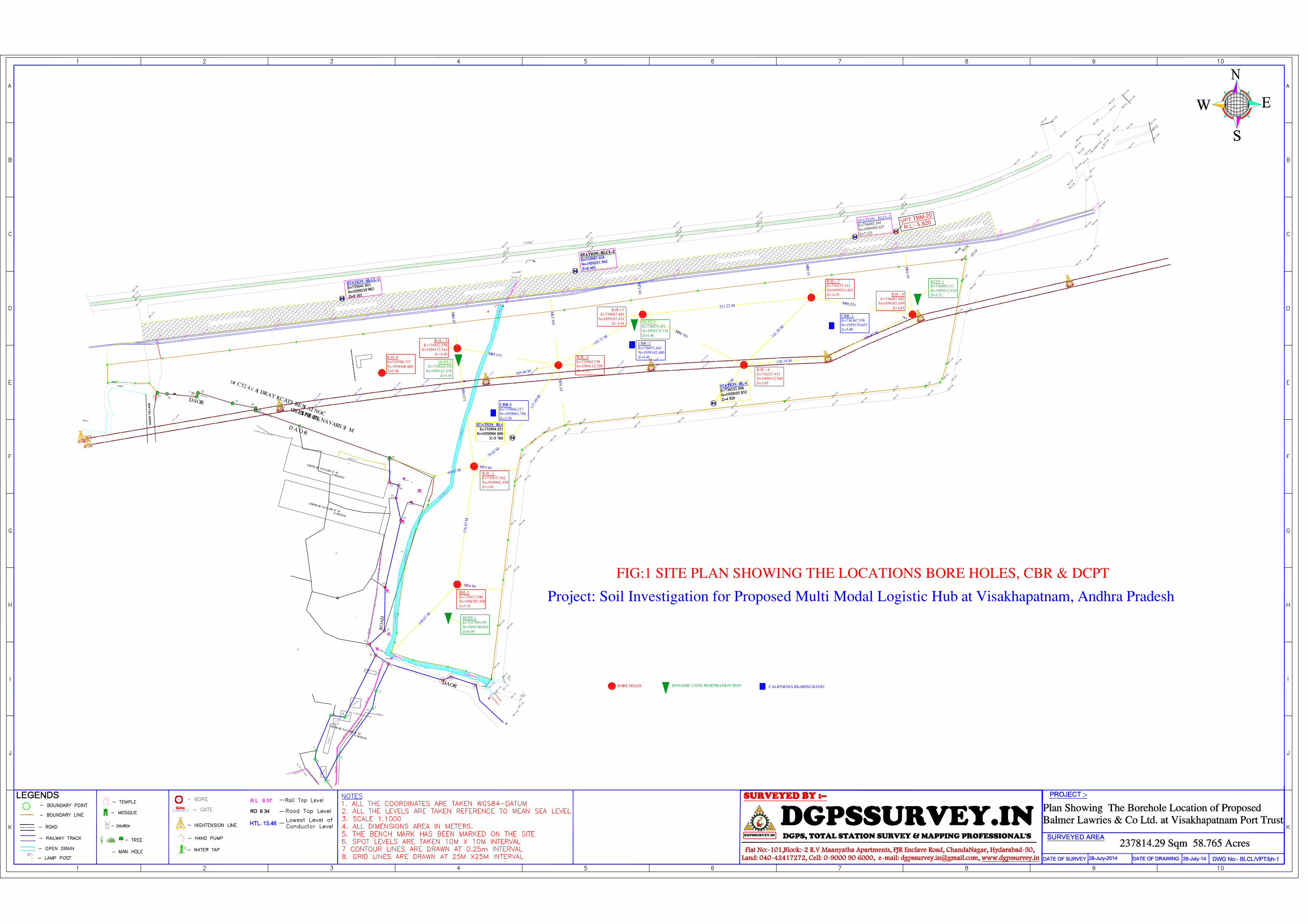
16. FIG–1: Site Plan showing locations of Bore Holes, CBR and DCPT
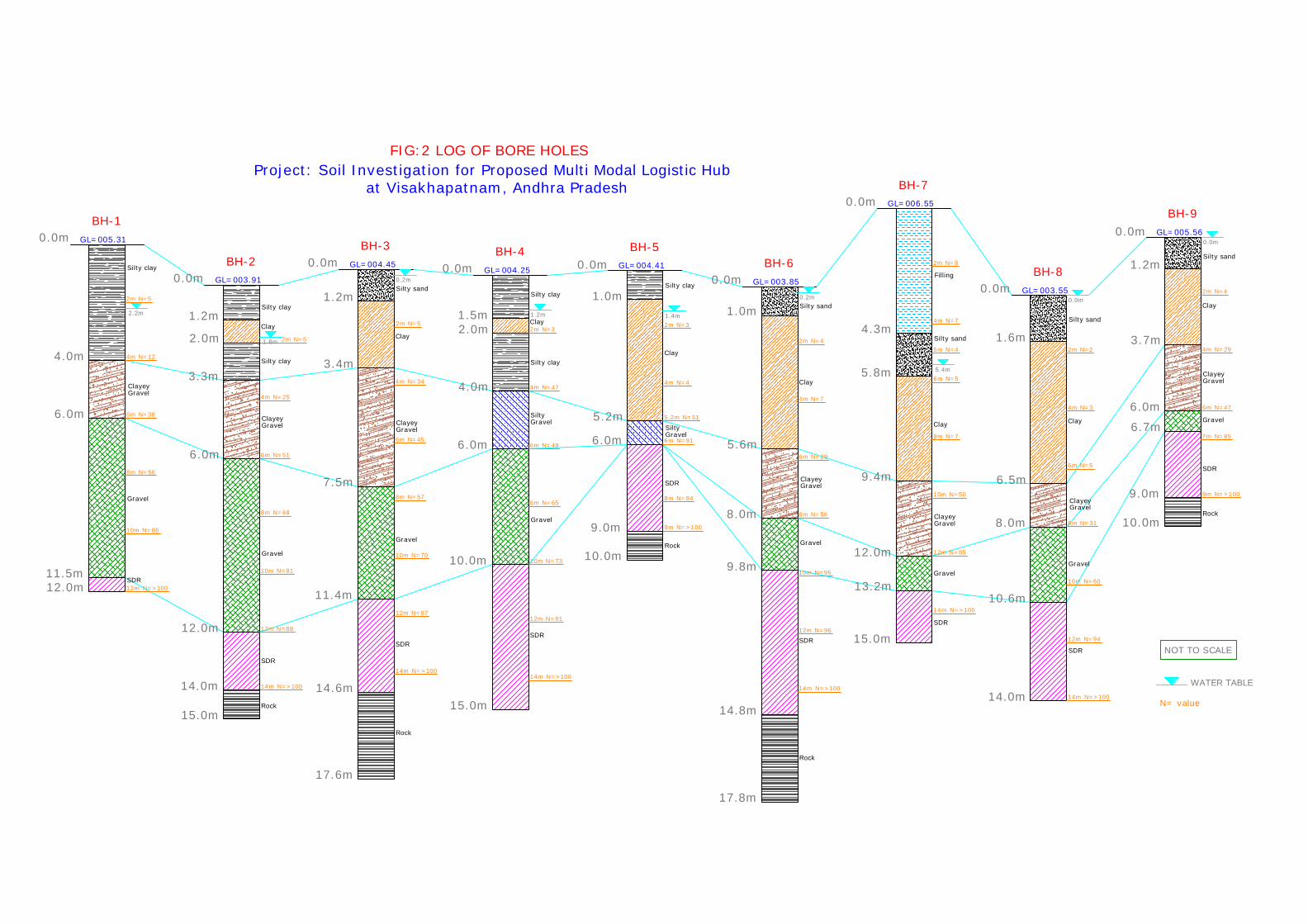
17. FIG–2: Combined Log of Bore holes
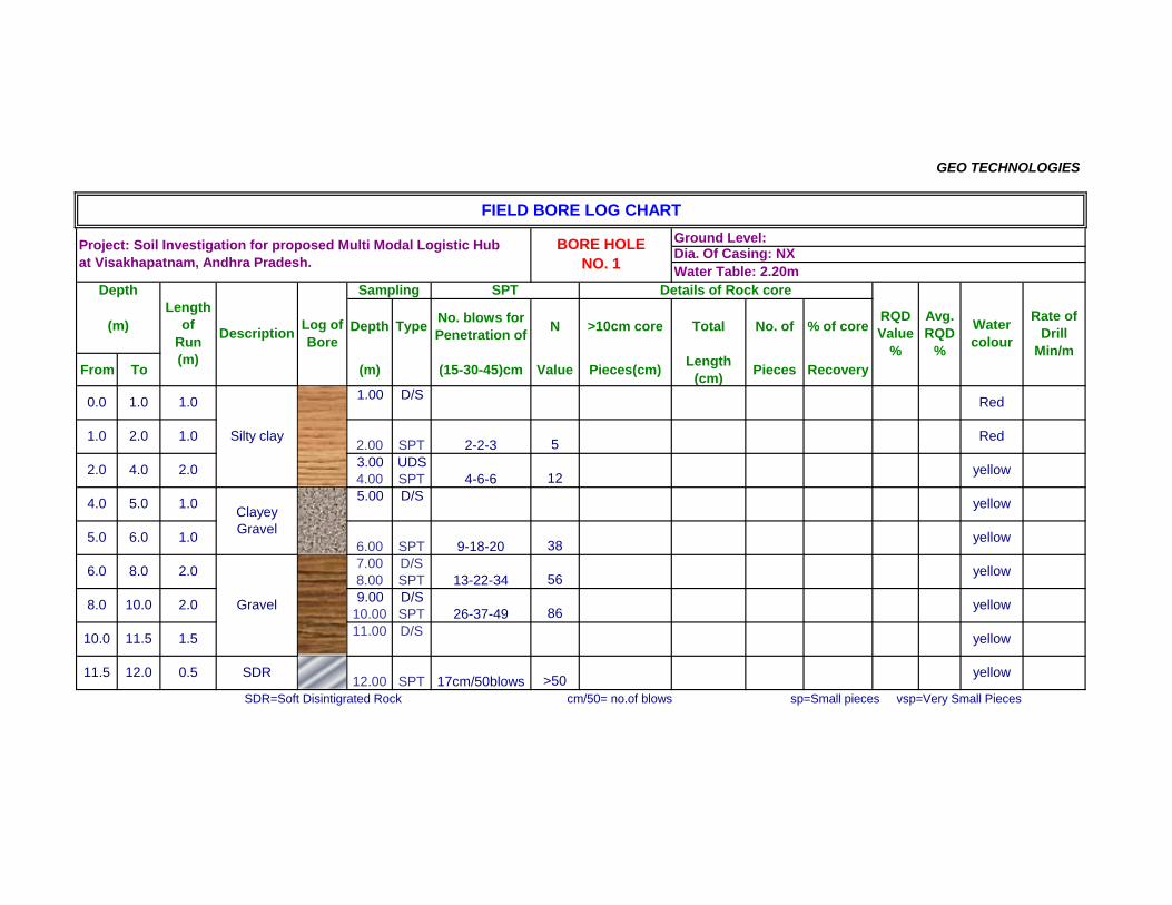
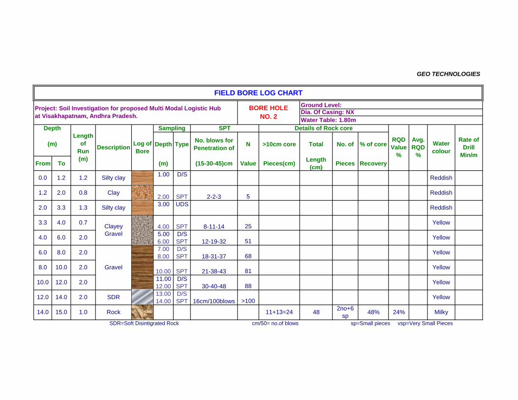
19. Annexure-1: Field Bore Log charts
20. Annexure-2: BIS Codes
3
GEO TECHNOLOGIES
Balmer Lawrie & Co. Ltd.
1. INTRODUCTION
The work of soil investigation for the proposed Multi Modal Logistic Hub project at VPT,
Visakhapatnam, was assigned to M/s GEO TECHNOLOGIES, vide Work Order No.
BL/NI/MMLH/Vizag/Wo-001 dated: 22-05-2014 from M/s Balmer Lawrie & Co. Ltd., Kolkata.
Geotechnical investigations were carried out by drilling Nine (09) bore holes, conducting
Standard Penetration Tests, collecting soil and rock samples and conducting relevant
laboratory tests. California Bearing Ratio (CBR) tests and Dynamic Cone Penetration Tests
(DCPT) were also conducted.
Fig.1. gives the Site Plan of the proposed development, showing the locations of bore holes,
California Bearing Ratio (CBR) tests and Dynamic Cone Penetration Tests (DCPT).
The aim of investigations is to determine the depth of foundations and the Safe Bearing
Capacity based on Field and Laboratory Investigations.
All the investigations are carried out in accordance with the relevant BIS (IS) Codes.
4
GEO TECHNOLOGIES
Balmer Lawrie & Co. Ltd.
2. FIELD INVESTIGATIONS
OBJECTIVE:
The sub soil investigation was carried out to determine the nature of stratum and engineering
properties of soil which may affect the mode of construction of the proposed structures, and
to recommend the SBC of foundations accordingly.
BORE HOLES:
Nine (09) bore holes (BH-1 to BH-9) were drilled at the locations fixed by the client (Fig.1).
Table-1 gives the details of the bore holes drilled.
The bore holes were planned so as to yield complete information in the effective and critical
zones under the foundations.
DRILLING:
Rotary Drilling was performed as per IS: 1892. The size of the casing used was 125 to 75
mm yielding samples of NX size.
The following information was collected during the drilling operations:
Depth-wise soil profile
Depth and results of SPT
Details of soil and rock samples collected
Core recovery & RQD of rock
Color of return water

5
GEO TECHNOLOGIES
Balmer Lawrie & Co. Ltd.
STANDARD PENETRATION TEST (SPT):
Standard Penetration Tests were conducted at frequent intervals in the bore holes. These
tests were performed as specified in IS: 2131-1981. In this test, a standard weight is
dropped through 75 cm height to drive the split-spoon sampler, and the number of blows
required to effect three consecutive 15 cm penetrations is recorded. The first 15 cm
penetration is considered as seating drive and neglected. Thereafter, the split-spoon sampler
is further driven for 30 cm penetration or 100 blows, whichever is reached earlier. The total
number of blows for the second and third 15 cm penetrations is designated as penetration
resistance N. If less than 30 cm is penetrated, the number of blows and the depth
penetrated are recorded, and N value is recoded as N > 100. If the number of blows exceeds
100, Refusal is said to have been reached and further testing is discontinued.
FIELD BORE LOGS:
All the details collected from the field operations are presented in Logs of Bore holes given in
Annexure-1. These logs contain depth wise strata details, sample collection data, results of
Standard Penetration Tests, core recovery data, and colour of return water etc.
SAMPLES:
All the samples collected were properly packed, labeled and transported to Geo
Technologies Soil Testing Laboratory at Hyderabad.
CBR TESTS :
The CBR tests (CBR-1 to CBR-3) were conducted at three (3) locations shown in the site
plan (Fig.1), at a depth of 30 cm. The tests were conducted in accordance with IS: 2720
(Part-31): 1969 – Field Determination of California Bearing Ratio.
The equipment comprises mechanical loading jack of 10 ton capacity, with bracket and
swivel head. A bridge support is provided for a calibrated proving ring of capacity 5000 kg,
with a dial gauge to read to an accuracy of 0.002 mm. A 50-mm dia metal penetration piston
6
GEO TECHNOLOGIES
Balmer Lawrie & Co. Ltd.
is used for penetration. A dial gauge held in a universal dial gauge clamp, supported by
datum bar is used for measuring the penetration. One 5-kg, 250-mm dia annular metal
weight, with a 53-mm dia central hole and two circular slotted weights of 5 kg & two circular
slotted weights of 10 kg are used as surcharge weights. Equipment to provide reaction
(truss, truck) are located such that the beam is over the centre of the surface under test.
The load is applied at the rate of 1.25 mm / min. Load readings are recorded for penetrations
of 0.5, 1.0, 1.5, 2.0, 2.5, 3.0, 4.0, 5.0, 7.5, 10.0 & 12.5 mm.
Each test was conducted with three trials (at 3 adjacent points) in unsoaked and soaked
conditions.
Soil samples were also collected from the test locations for laboratory CBR tests.
DCPT TESTS :
Dynamic Cone Penetration tests were conducted at four locations as per IS Code: 4968
(Part-1): 1976 – Method for Subsurface Sounding for Soils: Part 1: Dynamic Method using 50
mm Cone without Bentonite slurry.
A 50 mmm dia, 60 cone screwed to the driving rod and hammer assembly was used for the
test. This assembly is kept vertical with the cone resting on the ground to be tested. The
cone is then driven into the soil by allowing a 65 kg hammer to fall freely through a height of
750 mm each time. The number of blows per every 100 mm penetration of the cone is noted.
The process is repeated for three consecutive 100 mm penetration and the sum of number of
blows is recorded as DCPT value (Ncd). When the Ncd value reaches 100, it is treated as
refusal and driving is stopped.
7
GEO TECHNOLOGIES
Balmer Lawrie & Co. Ltd.
3. LABORATORY TESTING
The samples were tested at the Soil Testing Laboratory of GEO TECHNOLOGIES at
Hyderabad.
The following tests were performed on the Soil samples:
Natural Moisture Content
Atterberg’s Limits (Liquid Limit & Plastic Limit)
Bulk density & dry Density
Specific gravity
Particle size distribution (a) Sieve (b) Hydrometer
Triaxial Shear / Direct Shear
Consolidation Test
Lab CBR Test (Unsoaked & Soaked)
Chemical Analysis for pH, Sulphate & Chloride on soil / water
All the tests were conducted in accordance with IS: 2720 (Methods of Tests for Soils).
The following tests were conducted on rock samples:
Unit weight of rock (Density)
Water Absorption
Porosity
Uniaxial Crushing Strength
These tests were conducted in accordance with IS: 1124 – 1974 and IS: 9143 – 1979.
8
GEO TECHNOLOGIES
Balmer Lawrie & Co. Ltd.
4. ANALYSIS OF DATA & RESULTS
BORE HOLE DATA:
From the field observation charts, sub-soil profiles, showing the variation of soil strata with
depth and SPT (N) values, are drawn for all the 9 bore holes.
Fig. 2 gives the Combined Log of the 9 bore holes.
Based on the results of lab tests, physical and engineering properties of soil and rock
samples are tabulated.
Tables – 2(a) to 2(c) give the results of lab testing of soil samples.
Table – 3 gives the results of testing of rock samples.
Tables – 4(a) & 4(b) give the results of chemical tests on soil and water samples.
ANALYSIS OF CBR DATA:
CBR test data is analyzed for calculating CBR value as per IS Code: 2720 (Part 31): 1969,
Clause 5.
From the stress-penetration curves, the stress values corresponding to 2.5 mm and 5.0 mm
penetrations are read, and the California Bearing Ratio is calculated as:
CBR = (PT / PS) x 100,
Where PT = Test stress value corresponding to the chosen penetration value, and
PS = Standard stress for the same penetration value, taken from Table-1 of the Code (PS (2.5
mm) = 70 kg/cm2; PS (5 mm) = 105 kg/cm2).
Tables – 5 (a) & 5(b) give the results of Field and Lab CBR Tests.
ANALYSIS OF DCPT DATA:
The results Dynamic Cone Penetration Tests are presented as Ncd value versus depth.
Table – 6 gives DCPT results for four locations.
DCPT (Ncd) values are, by and large, correlatable with SPT values at the corresponding
depths in the nearby borehole data.
9
GEO TECHNOLOGIES
Balmer Lawrie & Co. Ltd.
5. SUB-SOIL PROFILE
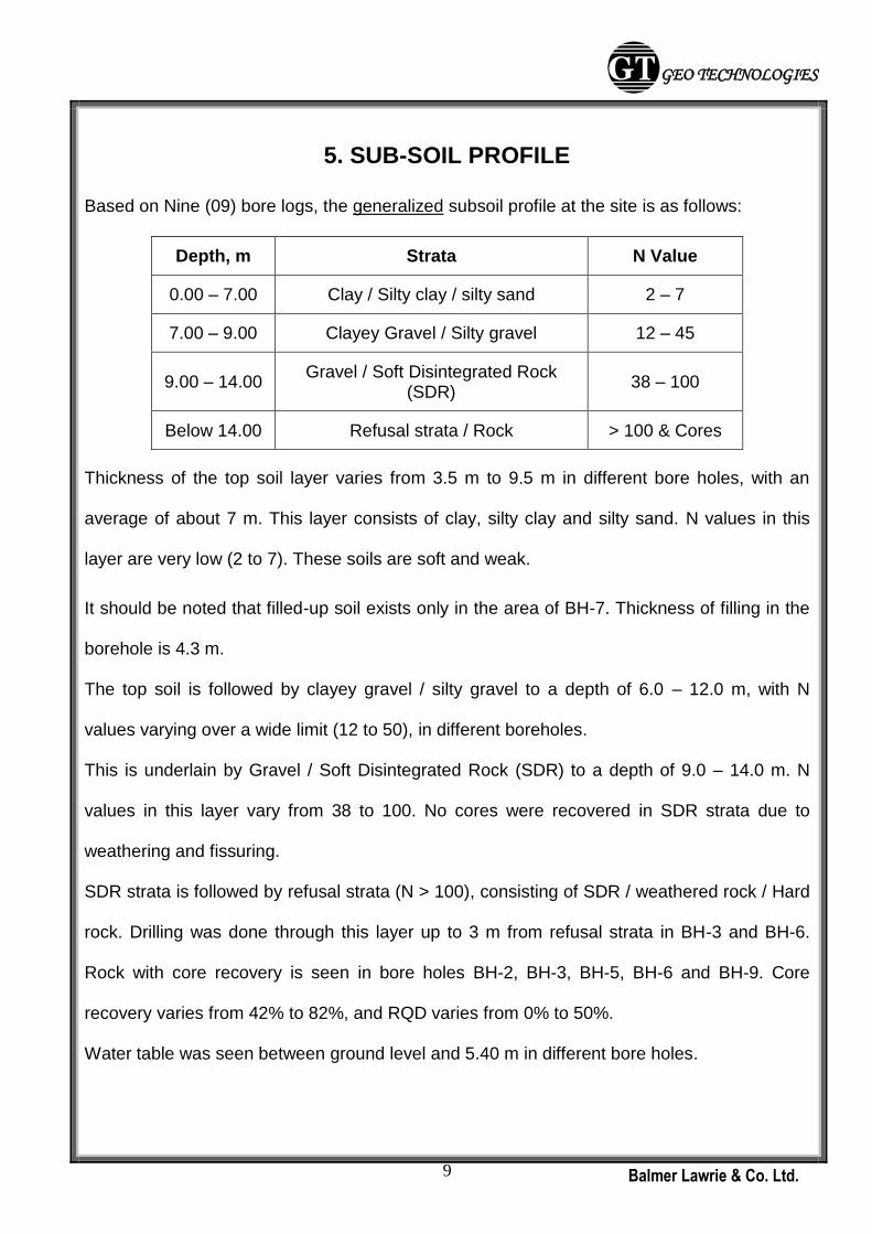
Based on Nine (09) bore logs, the generalized subsoil profile at the site is as follows:
Depth, m Strata N Value
0.00 – 7.00 Clay / Silty clay / silty sand 2 – 7
7.00 – 9.00 Clayey Gravel / Silty gravel 12 – 45
9.00 – 14.00 Gravel / Soft Disintegrated Rock
(SDR) 38 – 100
Below 14.00 Refusal strata / Rock > 100 & Cores
Thickness of the top soil layer varies from 3.5 m to 9.5 m in different bore holes, with an
average of about 7 m. This layer consists of clay, silty clay and silty sand. N values in this
layer are very low (2 to 7). These soils are soft and weak.
It should be noted that filled-up soil exists only in the area of BH-7. Thickness of filling in the
borehole is 4.3 m.
The top soil is followed by clayey gravel / silty gravel to a depth of 6.0 – 12.0 m, with N
values varying over a wide limit (12 to 50), in different boreholes.
This is underlain by Gravel / Soft Disintegrated Rock (SDR) to a depth of 9.0 – 14.0 m. N
values in this layer vary from 38 to 100. No cores were recovered in SDR strata due to
weathering and fissuring.
SDR strata is followed by refusal strata (N > 100), consisting of SDR / weathered rock / Hard
rock. Drilling was done through this layer up to 3 m from refusal strata in BH-3 and BH-6.
Rock with core recovery is seen in bore holes BH-2, BH-3, BH-5, BH-6 and BH-9. Core
recovery varies from 42% to 82%, and RQD varies from 0% to 50%.
Water table was seen between ground level and 5.40 m in different bore holes.
10
GEO TECHNOLOGIES
Balmer Lawrie & Co. Ltd.
6. RECOMMENDATIONS
The following recommendations are made for the proposed Multi Modal Logistic Hub project
at VPT, Visakhapatnam. These recommendations are based on Standard Penetration Tests
and Laboratory Tests on samples from Nine (09) bore holes, three (3) Field and Lab CBR
tests, and four (4) Dynamic Cone Penetration Tests.
Sub-soil Profile:
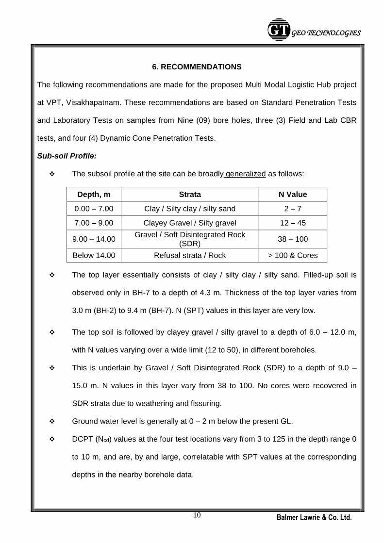
The subsoil profile at the site can be broadly generalized as follows:
Depth, m Strata N Value
0.00 – 7.00 Clay / Silty clay / silty sand 2 – 7
7.00 – 9.00 Clayey Gravel / Silty gravel 12 – 45
9.00 – 14.00 Gravel / Soft Disintegrated Rock
(SDR) 38 – 100
Below 14.00 Refusal strata / Rock > 100 & Cores
The top layer essentially consists of clay / silty clay / silty sand. Filled-up soil is
observed only in BH-7 to a depth of 4.3 m. Thickness of the top layer varies from
3.0 m (BH-2) to 9.4 m (BH-7). N (SPT) values in this layer are very low.
The top soil is followed by clayey gravel / silty gravel to a depth of 6.0 – 12.0 m,
with N values varying over a wide limit (12 to 50), in different boreholes.
This is underlain by Gravel / Soft Disintegrated Rock (SDR) to a depth of 9.0 –
15.0 m. N values in this layer vary from 38 to 100. No cores were recovered in
SDR strata due to weathering and fissuring.
Ground water level is generally at 0 – 2 m below the present GL.
DCPT (Ncd) values at the four test locations vary from 3 to 125 in the depth range 0
to 10 m, and are, by and large, correlatable with SPT values at the corresponding
depths in the nearby borehole data.
11
GEO TECHNOLOGIES
Balmer Lawrie & Co. Ltd.
Soil & Rock Properties:
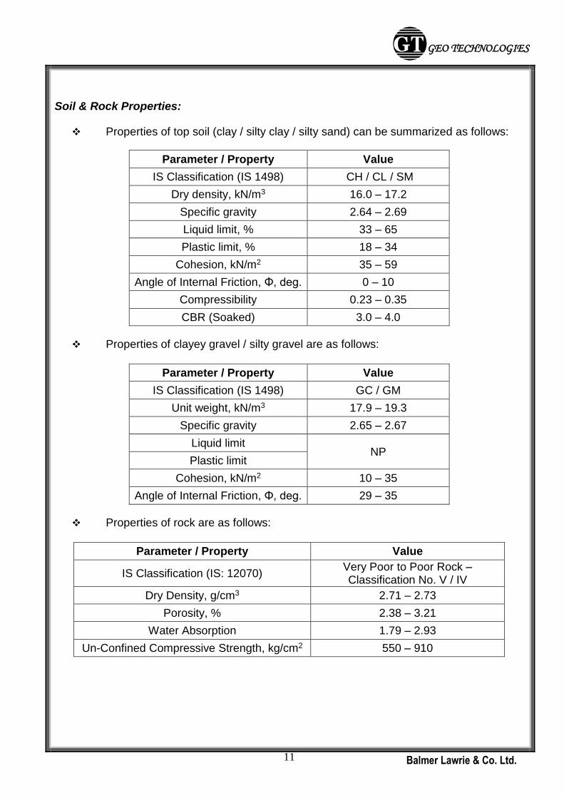
Properties of top soil (clay / silty clay / silty sand) can be summarized as follows:
Parameter / Property Value
IS Classification (IS 1498) CH / CL / SM
Dry density, kN/m3 16.0 – 17.2
Specific gravity 2.64 – 2.69
Liquid limit, % 33 – 65
Plastic limit, % 18 – 34
Cohesion, kN/m2 35 – 59
Angle of Internal Friction, Φ, deg. 0 – 10
Compressibility 0.23 – 0.35
CBR (Soaked) 3.0 – 4.0
Properties of clayey gravel / silty gravel are as follows:
Parameter / Property Value
IS Classification (IS 1498) GC / GM
Unit weight, kN/m3 17.9 – 19.3
Specific gravity 2.65 – 2.67
Liquid limit NP
Plastic limit
Cohesion, kN/m2 10 – 35
Angle of Internal Friction, Φ, deg. 29 – 35
Properties of rock are as follows:
Parameter / Property Value
IS Classification (IS: 12070) Very Poor to Poor Rock – Classification No. V / IV
Dry Density, g/cm3 2.71 – 2.73
Porosity, % 2.38 – 3.21
Water Absorption 1.79 – 2.93
Un-Confined Compressive Strength, kg/cm2 550 – 910
12
GEO TECHNOLOGIES
Balmer Lawrie & Co. Ltd.
FOUNDATIONS:
Open foundations:
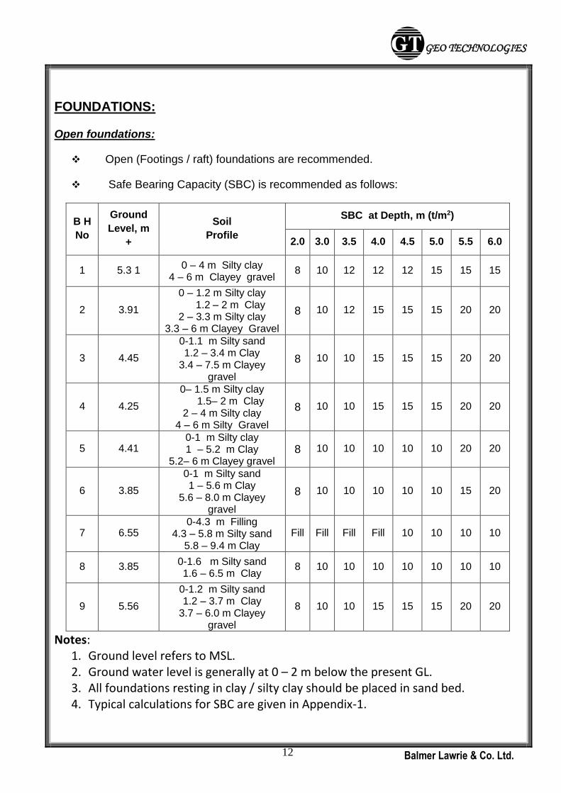
Open (Footings / raft) foundations are recommended.
Safe Bearing Capacity (SBC) is recommended as follows:
B H
No
Ground
Level, m
+
Soil
Profile
SBC at Depth, m (t/m2)
2.0 3.0 3.5 4.0 4.5 5.0 5.5 6.0
1 5.3 1 0 – 4 m Silty clay
4 – 6 m Clayey gravel 8 10 12 12 12 15 15 15
2 3.91
0 – 1.2 m Silty clay 1.2 – 2 m Clay
2 – 3.3 m Silty clay 3.3 – 6 m Clayey Gravel
8 10 12 15 15 15 20 20
3 4.45
0-1.1 m Silty sand 1.2 – 3.4 m Clay
3.4 – 7.5 m Clayey gravel
8 10 10 15 15 15 20 20
4 4.25
0– 1.5 m Silty clay 1.5– 2 m Clay
2 – 4 m Silty clay 4 – 6 m Silty Gravel
8 10 10 15 15 15 20 20
5 4.41 0-1 m Silty clay 1 – 5.2 m Clay
5.2– 6 m Clayey gravel 8 10 10 10 10 10 20 20
6 3.85
0-1 m Silty sand 1 – 5.6 m Clay
5.6 – 8.0 m Clayey gravel
8 10 10 10 10 10 15 20
7 6.55 0-4.3 m Filling
4.3 – 5.8 m Silty sand 5.8 – 9.4 m Clay
Fill Fill Fill Fill 10 10 10 10
8 3.85 0-1.6 m Silty sand 1.6 – 6.5 m Clay
8 10 10 10 10 10 10 10
9 5.56
0-1.2 m Silty sand 1.2 – 3.7 m Clay
3.7 – 6.0 m Clayey gravel
8 10 10 15 15 15 20 20
Notes: 1. Ground level refers to MSL. 2. Ground water level is generally at 0 – 2 m below the present GL. 3. All foundations resting in clay / silty clay should be placed in sand bed. 4. Typical calculations for SBC are given in Appendix-1.
13
GEO TECHNOLOGIES
Balmer Lawrie & Co. Ltd.
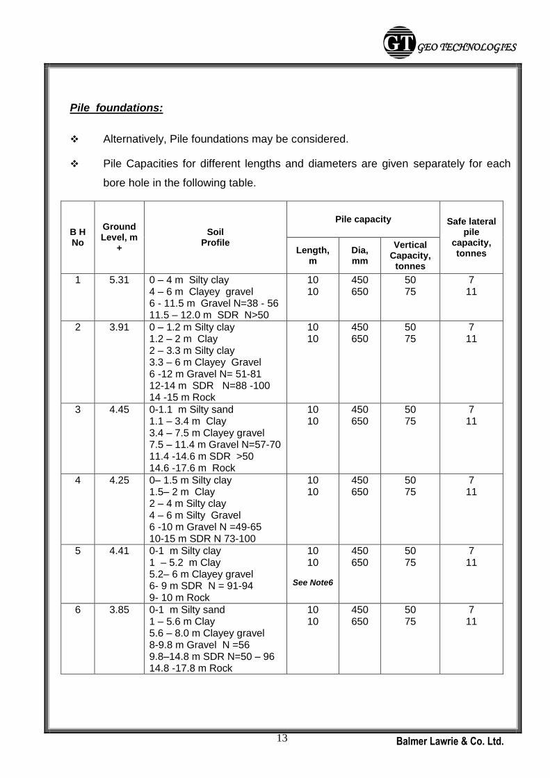
Pile foundations:
Alternatively, Pile foundations may be considered.
Pile Capacities for different lengths and diameters are given separately for each
bore hole in the following table.
B H No
Ground Level, m
+
Soil Profile
Pile capacity Safe lateral pile
capacity, tonnes Length,
m Dia, mm
Vertical Capacity,
tonnes
1 5.31 0 – 4 m Silty clay 4 – 6 m Clayey gravel 6 - 11.5 m Gravel N=38 - 56 11.5 – 12.0 m SDR N>50
10 10
450 650
50 75
7 11
2 3.91 0 – 1.2 m Silty clay 1.2 – 2 m Clay 2 – 3.3 m Silty clay 3.3 – 6 m Clayey Gravel 6 -12 m Gravel N= 51-81 12-14 m SDR N=88 -100 14 -15 m Rock
10 10
450 650
50 75
7 11
3 4.45 0-1.1 m Silty sand 1.1 – 3.4 m Clay 3.4 – 7.5 m Clayey gravel 7.5 – 11.4 m Gravel N=57-70 11.4 -14.6 m SDR >50 14.6 -17.6 m Rock
10 10
450 650
50 75
7 11
4 4.25 0– 1.5 m Silty clay 1.5– 2 m Clay 2 – 4 m Silty clay 4 – 6 m Silty Gravel 6 -10 m Gravel N =49-65 10-15 m SDR N 73-100
10 10
450 650
50 75
7 11
5 4.41 0-1 m Silty clay 1 – 5.2 m Clay 5.2– 6 m Clayey gravel 6- 9 m SDR N = 91-94 9- 10 m Rock
10 10
See Note6
450 650
50 75
7 11
6 3.85 0-1 m Silty sand 1 – 5.6 m Clay 5.6 – 8.0 m Clayey gravel 8-9.8 m Gravel N =56 9.8–14.8 m SDR N=50 – 96 14.8 -17.8 m Rock
10 10
450 650
50 75
7 11
14
GEO TECHNOLOGIES
Balmer Lawrie & Co. Ltd.
B H No
Ground Level, m
+
Soil Profile
Pile capacity Safe lateral pile
capacity, tonnes Length,
m Dia, mm
Vertical Capacity,
tonnes
7 6.55 0-4.3 m Filling 4.3 – 5.8 m Silty sand 5.8 – 9.4 m Clay 9.4 -13.2 m Clayey gravel (N= 50-85) 13.2 -15 m SDR N>50
10 10
450 650
50 75
7 11
8 3.85 0-1.6 m Silty sand 1.6 – 6.5 m Clay 6.5 - 8 m Clayey gravel 8 – 10.6 m Gravel N = 31-60 10.6 – 14 m SDR N=50-94
10 10
450 650
50 75
7 11
9 5.56 0-1.2 m Silty sand 1.2 – 3.7 m Clay 3.7 – 6.0 m Clayey gravel 6.0 – 6.7 m Gravel 6.7 – 9.0 m SDR N=50-85 9-10 m Rock
10 10
See Note6
450 650
50 75
7 11
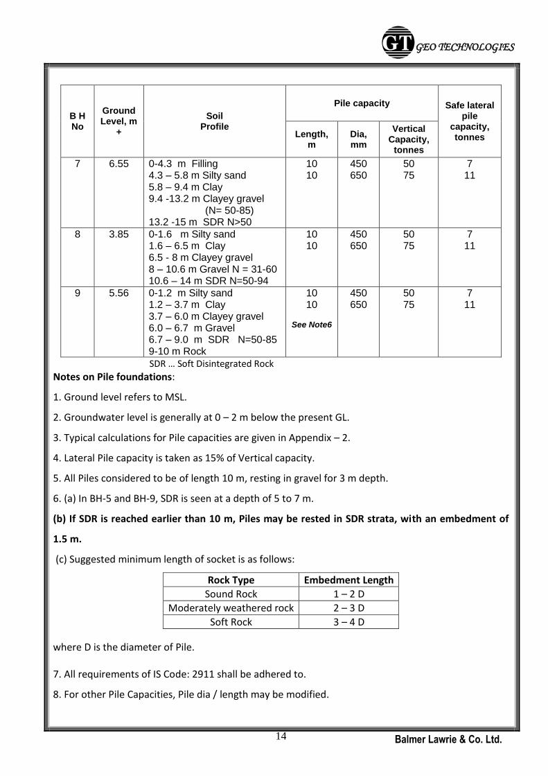
SDR … Soft Disintegrated Rock
Notes on Pile foundations:
1. Ground level refers to MSL.
2. Groundwater level is generally at 0 – 2 m below the present GL.
3. Typical calculations for Pile capacities are given in Appendix – 2.
4. Lateral Pile capacity is taken as 15% of Vertical capacity.
5. All Piles considered to be of length 10 m, resting in gravel for 3 m depth.
6. (a) In BH-5 and BH-9, SDR is seen at a depth of 5 to 7 m.
(b) If SDR is reached earlier than 10 m, Piles may be rested in SDR strata, with an embedment of
1.5 m.
(c) Suggested minimum length of socket is as follows:
where D is the diameter of Pile. 7. All requirements of IS Code: 2911 shall be adhered to.
8. For other Pile Capacities, Pile dia / length may be modified.
Rock Type Embedment Length
Sound Rock 1 – 2 D
Moderately weathered rock 2 – 3 D
Soft Rock 3 – 4 D
15
GEO TECHNOLOGIES
Balmer Lawrie & Co. Ltd.
Boundary wall foundations
Specific Recommendations for Boundary Wall Foundation:
The soils from 0 – 7 m are weak and soft soils (Clay /silty clay/silty sand). N values are less
than 10.
Considering the soft soils, the following alternatives are suggested:
Open foundations at a depth of 3 m with SBC of 10 t / sq m, and sand bed. SBC
calculations are given in Appendix – 1
Alternatively, 10 m long Piles may be used. Pile dia may be 300 mm with a vertical
pile capacity of 20 tonnes. Pile capacity calculations are given in Appendix-3.
PAVEMENT:
It should be noted that the top soil essentially consists of clay / silty clay / silty sand.
Thickness of this layer varies from 3.0 m to 9.5 m below existing ground level in
different boreholes.
Filled up soil of thickness 4.3 m exists in the area of Bore Hole-7.
Soaked CBR values of the top soil (clay/silty clay/silty sand) are quite low (3% to 4%).
Design:
As per Tender Document, Axle load transferred for each side of front axle of container
handling ‘Reach Stacker’ equipment is taken as 50 MT.
Sri Mohan Kumar, Manager, Railway Division, AARVEE Consultants, has given
Cumulative Standard Axles as 1.971 million times with full load over the surface.
From IRC: 37 – 2001 (Guidelines for Design of Flexible Pavments), Fig. 1 ( Pavement
design Thickness Chart ),
For CBR = 3 %, and Cumulative Standard Axles = 2 million,
Total Pavement Thickness T = 580 mm, say 600 mm
16
GEO TECHNOLOGIES
Balmer Lawrie & Co. Ltd.
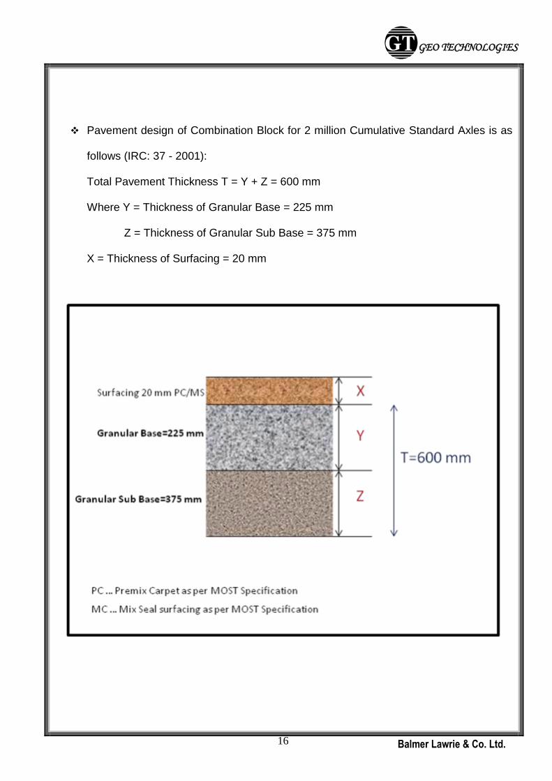
Pavement design of Combination Block for 2 million Cumulative Standard Axles is as
follows (IRC: 37 - 2001):
Total Pavement Thickness T = Y + Z = 600 mm
Where Y = Thickness of Granular Base = 225 mm
Z = Thickness of Granular Sub Base = 375 mm
X = Thickness of Surfacing = 20 mm
17
GEO TECHNOLOGIES
Balmer Lawrie & Co. Ltd.
Base Material:
This requires the load spreading properties to reduce the stresses on the subgrade.
This has an important bearing on the performance of block pavement. Since the
available strata are unsuitable, base course should consist of unbound crushed rock,
water bound macadam, wet mix macadam, cement-bound crushed rock / granular
materials, and lean cement concrete.
In broad terms, whenever the subgrade is weak (with CBR < 5 %, as in the present
case), use of bound granular materials like cement treated crushed rock, requiring a
relatively thinner base, is recommended.
Sub - base Material:
The quality of sub-base materials includes natural gravels, cement treated gravels,
sand stabilized sub grade materials. The quality of sub grade materials should be in
conformance with IRC: 37 -2001 (Guidelines for the Design of Flexible Pavements).
Drainage:
Drainage of the pavement structural section improves its performance. Adequately
designed sub – surface drainage system consisting of an open graded drainage layer
with collector and outlet pipes should be provided (IRC: 37- 2001).
18
GEO TECHNOLOGIES
Balmer Lawrie & Co. Ltd.
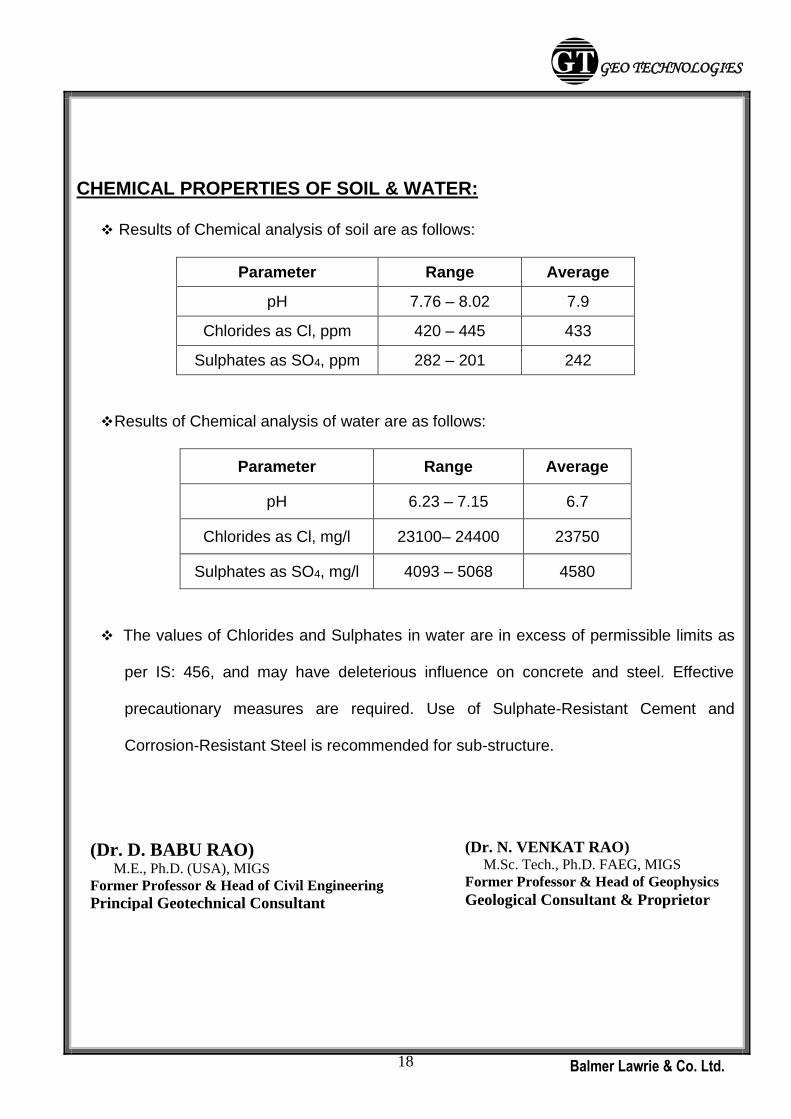
CHEMICAL PROPERTIES OF SOIL & WATER:
Results of Chemical analysis of soil are as follows:
Parameter Range Average
pH 7.76 – 8.02 7.9
Chlorides as Cl, ppm 420 – 445 433
Sulphates as SO4, ppm 282 – 201 242
Results of Chemical analysis of water are as follows:
Parameter Range Average
pH 6.23 – 7.15 6.7
Chlorides as Cl, mg/l 23100– 24400 23750
Sulphates as SO4, mg/l 4093 – 5068 4580
The values of Chlorides and Sulphates in water are in excess of permissible limits as
per IS: 456, and may have deleterious influence on concrete and steel. Effective
precautionary measures are required. Use of Sulphate-Resistant Cement and
Corrosion-Resistant Steel is recommended for sub-structure.
(Dr. D. BABU RAO) M.E., Ph.D. (USA), MIGS
Former Professor & Head of Civil Engineering
Principal Geotechnical Consultant
(Dr. N. VENKAT RAO) M.Sc. Tech., Ph.D. FAEG, MIGS
Former Professor & Head of Geophysics
Geological Consultant & Proprietor
19
GEO TECHNOLOGIES
Balmer Lawrie & Co. Ltd.
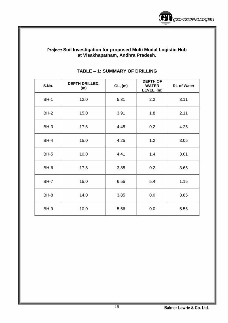
Project: Soil Investigation for proposed Multi Modal Logistic Hub
at Visakhapatnam, Andhra Pradesh.
TABLE – 1: SUMMARY OF DRILLING
S.No. DEPTH DRILLED,
(m) GL, (m)
DEPTH OF WATER
LEVEL, (m) RL of Water
BH-1 12.0 5.31 2.2 3.11
BH-2 15.0 3.91 1.8 2.11
BH-3 17.6 4.45 0.2 4.25
BH-4 15.0 4.25 1.2 3.05
BH-5 10.0 4.41 1.4 3.01
BH-6 17.8 3.85 0.2 3.65
BH-7 15.0 6.55 5.4 1.15
BH-8 14.0 3.85 0.0 3.85
BH-9 10.0 5.56 0.0 5.56
20
GEO TECHNOLOGIES
Balmer Lawrie & Co. Ltd.
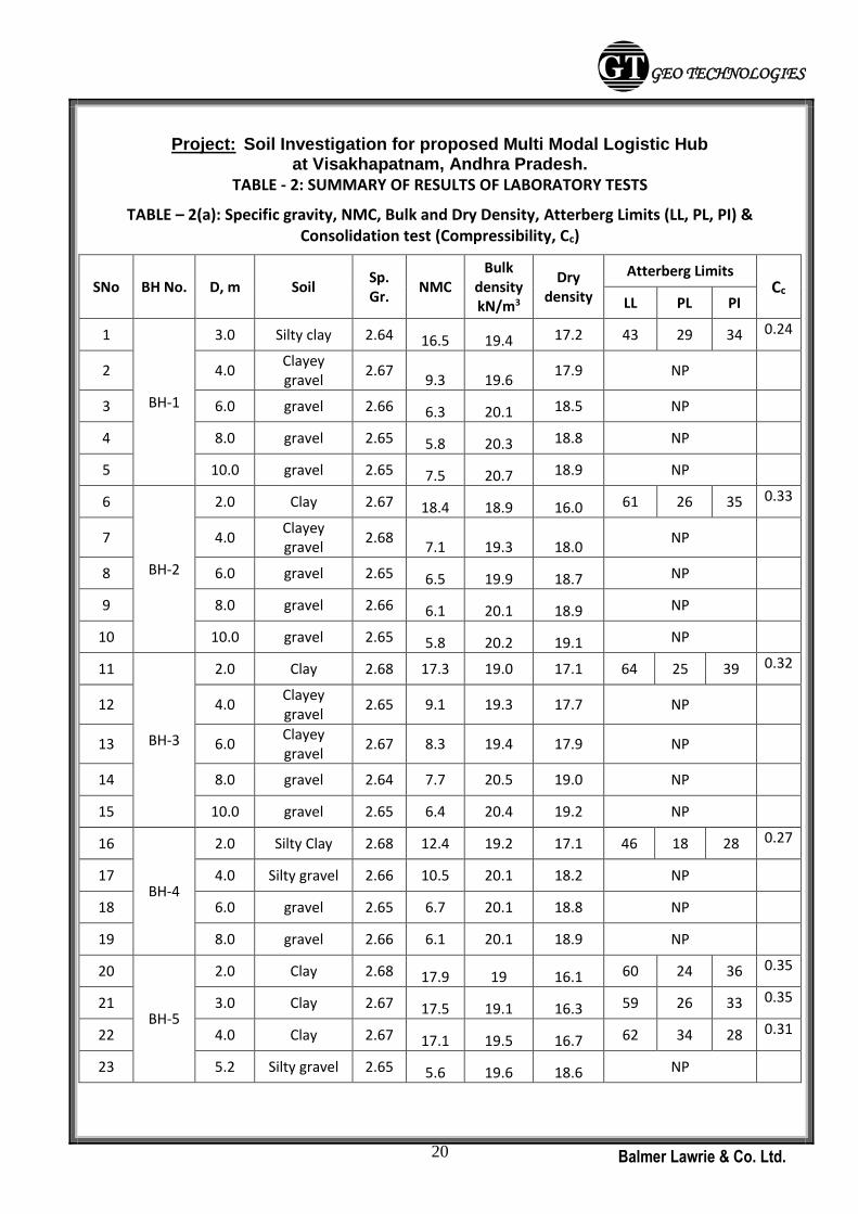
Project: Soil Investigation for proposed Multi Modal Logistic Hub
at Visakhapatnam, Andhra Pradesh. TABLE - 2: SUMMARY OF RESULTS OF LABORATORY TESTS
TABLE – 2(a): Specific gravity, NMC, Bulk and Dry Density, Atterberg Limits (LL, PL, PI) & Consolidation test (Compressibility, Cc)
SNo BH No. D, m Soil Sp. Gr.
NMC Bulk
density kN/m3
Dry density
Atterberg Limits Cc
LL PL PI
1
BH-1
3.0 Silty clay 2.64 16.5 19.4 17.2 43 29 34 0.24
2 4.0 Clayey gravel
2.67 9.3 19.6
17.9 NP
3 6.0 gravel 2.66 6.3 20.1 18.5 NP
4 8.0 gravel 2.65 5.8 20.3 18.8 NP
5 10.0 gravel 2.65 7.5 20.7 18.9 NP
6
BH-2
2.0 Clay 2.67 18.4 18.9 16.0 61 26 35 0.33
7 4.0 Clayey gravel
2.68 7.1 19.3 18.0
NP
8 6.0 gravel 2.65 6.5 19.9 18.7 NP
9 8.0 gravel 2.66 6.1 20.1 18.9 NP
10 10.0 gravel 2.65 5.8 20.2 19.1 NP
11
BH-3
2.0 Clay 2.68 17.3 19.0 17.1 64 25 39 0.32
12 4.0 Clayey gravel
2.65 9.1 19.3 17.7 NP
13 6.0 Clayey gravel
2.67 8.3 19.4 17.9 NP
14 8.0 gravel 2.64 7.7 20.5 19.0 NP
15 10.0 gravel 2.65 6.4 20.4 19.2 NP
16
BH-4
2.0 Silty Clay 2.68 12.4 19.2 17.1 46 18 28 0.27
17 4.0 Silty gravel 2.66 10.5 20.1 18.2 NP
18 6.0 gravel 2.65 6.7 20.1 18.8 NP
19 8.0 gravel 2.66 6.1 20.1 18.9 NP
20
BH-5
2.0 Clay 2.68 17.9 19 16.1 60 24 36 0.35
21 3.0 Clay 2.67 17.5 19.1 16.3 59 26 33 0.35
22 4.0 Clay 2.67 17.1 19.5 16.7 62 34 28 0.31
23 5.2 Silty gravel 2.65 5.6 19.6 18.6 NP
21
GEO TECHNOLOGIES
Balmer Lawrie & Co. Ltd.
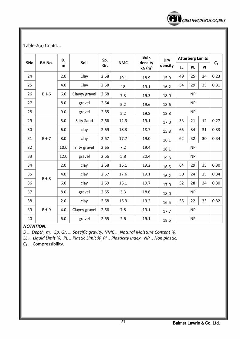
Table-2(a) Contd…
SNo BH No. D, m
Soil Sp. Gr.
NMC Bulk
density kN/m3
Dry density
Atterberg Limits Cc
LL PL PI
24
BH-6
2.0 Clay 2.68 19.1 18.9 15.9 49 25 24 0.23
25 4.0 Clay 2.68 18 19.1 16.2 54 29 35 0.31
26 6.0 Clayey gravel 2.68 7.3 19.3 18.0 NP
27 8.0 gravel 2.64 5.2 19.6 18.6 NP
28 9.0 gravel 2.65 5.2 19.8 18.8 NP
29
BH-7
5.0 Silty Sand 2.66 12.3 19.1 17.0 33 21 12 0.27
30 6.0 clay 2.69 18.3 18.7 15.8 65 34 31 0.33
31 8.0 clay 2.67 17.7 19.0 16.1 62 32 30 0.34
32 10.0 Silty gravel 2.65 7.2 19.4 18.1 NP
33 12.0 gravel 2.66 5.8 20.4 19.3 NP
34
BH-8
2.0 clay 2.68 16.1 19.2 16.5 64 29 35 0.30
35 4.0 clay 2.67 17.6 19.1 16.2 50 24 25 0.34
36 6.0 clay 2.69 16.1 19.7 17.0 52 28 24 0.30
37 8.0 gravel 2.65 3.3 18.6 18.0 NP
38
BH-9
2.0 clay 2.68 16.3 19.2 16.5 55 22 33 0.32
39 4.0 Clayey gravel 2.66 7.8 19.1 17.7 NP
40 6.0 gravel 2.65 2.6 19.1 18.6 NP
NOTATION: D … Depth, m, Sp. Gr. … Specific gravity, NMC … Natural Moisture Content %, LL … Liquid Limit %, PL .. Plastic Limit %, PI .. Plasticity Index, NP .. Non plastic, Cc … Compressibility.
22
GEO TECHNOLOGIES
Balmer Lawrie & Co. Ltd.
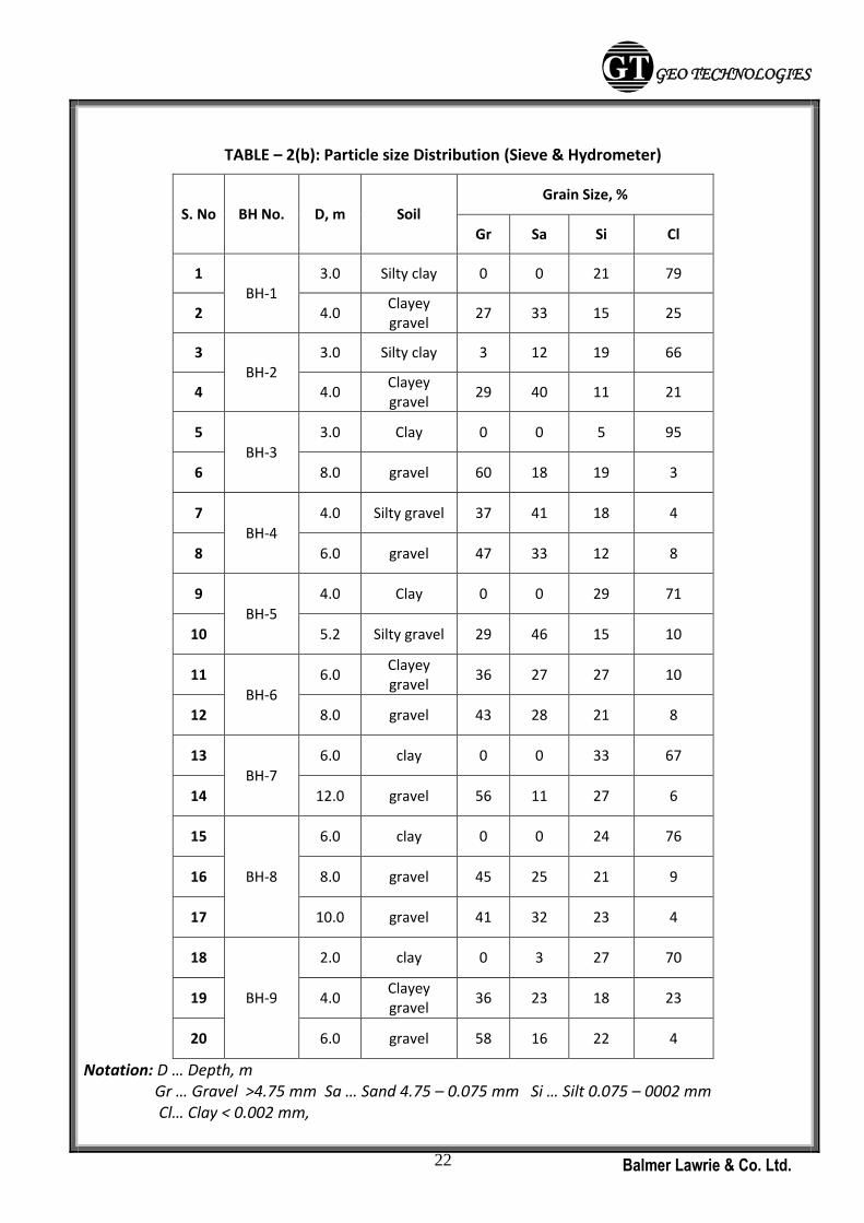
TABLE – 2(b): Particle size Distribution (Sieve & Hydrometer)
S. No BH No. D, m Soil Grain Size, %
Gr Sa Si Cl
1 BH-1
3.0 Silty clay 0 0 21 79
2 4.0 Clayey gravel
27 33 15 25
3 BH-2
3.0 Silty clay 3 12 19 66
4 4.0 Clayey gravel
29 40 11 21
5
BH-3
3.0 Clay 0 0 5 95
6 8.0 gravel 60 18 19 3
7
BH-4
4.0 Silty gravel 37 41 18 4
8 6.0 gravel 47 33 12 8
9
BH-5
4.0 Clay 0 0 29 71
10 5.2 Silty gravel 29 46 15 10
11
BH-6
6.0 Clayey gravel
36 27 27 10
12 8.0 gravel 43 28 21 8
13
BH-7
6.0 clay 0 0 33 67
14 12.0 gravel 56 11 27 6
15
BH-8
6.0 clay 0 0 24 76
16 8.0 gravel 45 25 21 9
17 10.0 gravel 41 32 23 4
18
BH-9
2.0 clay 0 3 27 70
19 4.0 Clayey gravel
36 23 18 23
20 6.0 gravel 58 16 22 4
Notation: D … Depth, m Gr … Gravel >4.75 mm Sa … Sand 4.75 – 0.075 mm Si … Silt 0.075 – 0002 mm Cl… Clay < 0.002 mm,
23
GEO TECHNOLOGIES
Balmer Lawrie & Co. Ltd.
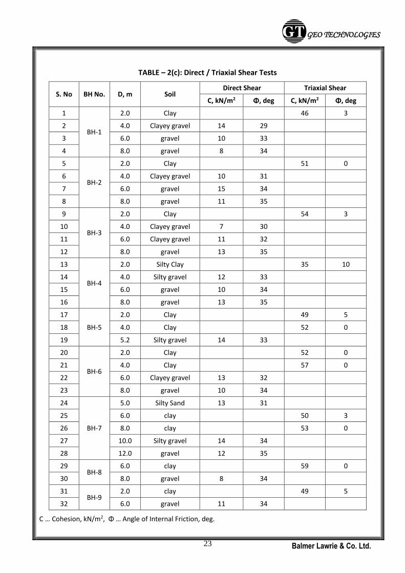
TABLE – 2(c): Direct / Triaxial Shear Tests
S. No BH No. D, m Soil Direct Shear Triaxial Shear
C, kN/m2 Φ, deg C, kN/m2 Φ, deg
1
BH-1
2.0 Clay 46 3
2 4.0 Clayey gravel 14 29
3 6.0 gravel 10 33
4 8.0 gravel 8 34
5
BH-2
2.0 Clay 51 0
6 4.0 Clayey gravel 10 31
7 6.0 gravel 15 34
8 8.0 gravel 11 35
9
BH-3
2.0 Clay 54 3
10 4.0 Clayey gravel 7 30
11 6.0 Clayey gravel 11 32
12 8.0 gravel 13 35
13
BH-4
2.0 Silty Clay 35 10
14 4.0 Silty gravel 12 33
15 6.0 gravel 10 34
16 8.0 gravel 13 35
17
BH-5
2.0 Clay 49 5
18 4.0 Clay 52 0
19 5.2 Silty gravel 14 33
20
BH-6
2.0 Clay 52 0
21 4.0 Clay 57 0
22 6.0 Clayey gravel 13 32
23 8.0 gravel 10 34
24
BH-7
5.0 Silty Sand 13 31
25 6.0 clay 50 3
26 8.0 clay 53 0
27 10.0 Silty gravel 14 34
28 12.0 gravel 12 35
29 BH-8
6.0 clay 59 0
30 8.0 gravel 8 34
31 BH-9
2.0 clay 49 5
32 6.0 gravel 11 34
C … Cohesion, kN/m2, Φ … Angle of Internal Friction, deg.
24
GEO TECHNOLOGIES
Balmer Lawrie & Co. Ltd.
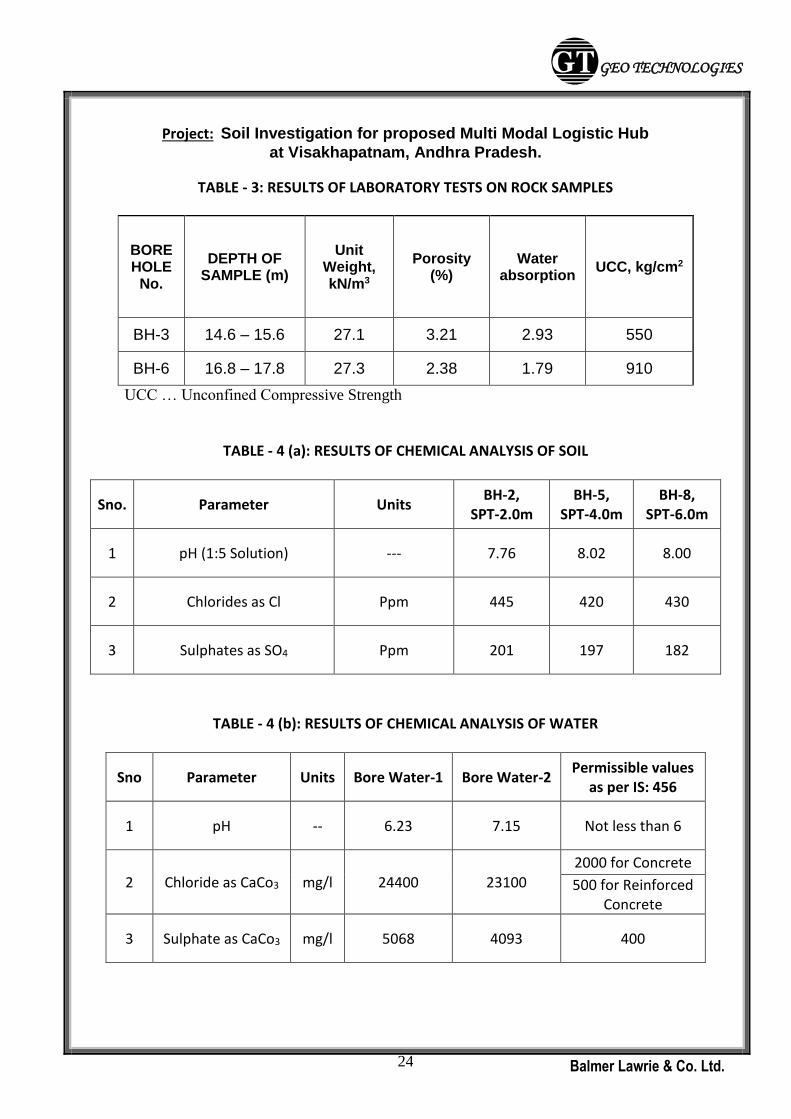
Project: Soil Investigation for proposed Multi Modal Logistic Hub
at Visakhapatnam, Andhra Pradesh.
TABLE - 3: RESULTS OF LABORATORY TESTS ON ROCK SAMPLES
BORE HOLE
No.
DEPTH OF SAMPLE (m)
Unit Weight, kN/m3
Porosity (%)
Water absorption
UCC, kg/cm2
BH-3 14.6 – 15.6 27.1 3.21 2.93 550
BH-6 16.8 – 17.8 27.3 2.38 1.79 910
UCC … Unconfined Compressive Strength
TABLE - 4 (a): RESULTS OF CHEMICAL ANALYSIS OF SOIL
Sno. Parameter Units BH-2,
SPT-2.0m BH-5,
SPT-4.0m BH-8,
SPT-6.0m
1 pH (1:5 Solution) --- 7.76 8.02 8.00
2 Chlorides as Cl Ppm 445 420 430
3 Sulphates as SO4 Ppm 201 197 182
TABLE - 4 (b): RESULTS OF CHEMICAL ANALYSIS OF WATER
Sno Parameter Units Bore Water-1 Bore Water-2 Permissible values
as per IS: 456
1 pH -- 6.23 7.15 Not less than 6
2 Chloride as CaCo3 mg/l 24400 23100 2000 for Concrete
500 for Reinforced Concrete
3 Sulphate as CaCo3 mg/l 5068 4093 400
25
GEO TECHNOLOGIES
Balmer Lawrie & Co. Ltd.
Project: Soil Investigation for proposed Multi Modal Logistic Hub
at Visakhapatnam, Andhra Pradesh.
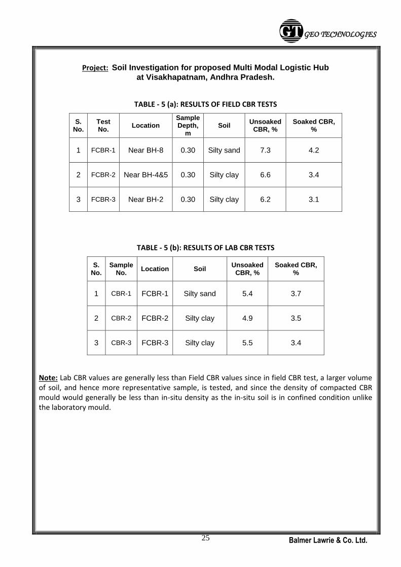
TABLE - 5 (a): RESULTS OF FIELD CBR TESTS
S. No.
Test No.
Location Sample Depth,
m Soil
Unsoaked CBR, %
Soaked CBR, %
1 FCBR-1 Near BH-8 0.30 Silty sand 7.3 4.2
2 FCBR-2 Near BH-4&5 0.30 Silty clay 6.6 3.4
3 FCBR-3 Near BH-2 0.30 Silty clay 6.2 3.1
TABLE - 5 (b): RESULTS OF LAB CBR TESTS
S. No.
Sample No.
Location Soil Unsoaked
CBR, % Soaked CBR,
%
1 CBR-1 FCBR-1 Silty sand 5.4 3.7
2 CBR-2 FCBR-2 Silty clay 4.9 3.5
3 CBR-3 FCBR-3 Silty clay 5.5 3.4
Note: Lab CBR values are generally less than Field CBR values since in field CBR test, a larger volume of soil, and hence more representative sample, is tested, and since the density of compacted CBR mould would generally be less than in-situ density as the in-situ soil is in confined condition unlike the laboratory mould.
26
GEO TECHNOLOGIES
Balmer Lawrie & Co. Ltd.
Project: Soil Investigation for proposed Multi Modal Logistic Hub
at Visakhapatnam, Andhra Pradesh.
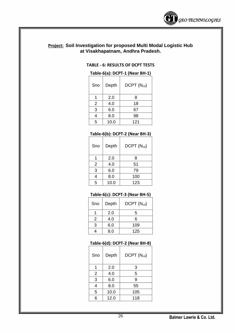
TABLE - 6: RESULTS OF DCPT TESTS
Table-6(a): DCPT-1 (Near BH-1)
Sno Depth DCPT (Ncd)
1 2.0 8
2 4.0 18
3 6.0 67
4 8.0 98
5 10.0 121
Table-6(b): DCPT-2 (Near BH-3)
Sno Depth DCPT (Ncd)
1 2.0 8
2 4.0 51
3 6.0 79
4 8.0 100
5 10.0 123
Table-6(c): DCPT-3 (Near BH-5)
Sno Depth DCPT (Ncd)
1 2.0 5
2 4.0 6
3 6.0 109
4 8.0 125
Table-6(d): DCPT-2 (Near BH-8)
Sno Depth DCPT (Ncd)
1 2.0 3
2 4.0 5
3 6.0 9
4 8.0 55
5 10.0 105
6 12.0 118
27
GEO TECHNOLOGIES
Balmer Lawrie & Co. Ltd.
Project: Soil Investigation for proposed Multi Modal Logistic Hub
at Visakhapatnam, Andhra Pradesh.
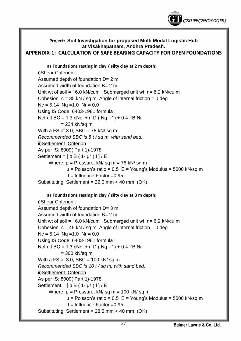
APPENDIX-1: CALCULATION OF SAFE BEARING CAPACITY FOR OPEN FOUNDATIONS
a) Foundations resting in clay / silty clay at 2 m depth:
i)Shear Criterion :
Assumed depth of foundation D= 2 m
Assumed width of foundation B= 2 m
Unit wt of soil = 16.0 kN/cum Submerged unit wt r’= 6.2 kN/cu m
Cohesion c = 35 kN / sq m Angle of internal friction = 0 deg
Nc = 5.14 Nq =1.0 Nr = 0,0
Using IS Code: 6403-1981 formula :
Net ult BC = 1.3 cNc + r’ D ( Nq - 1) + 0.4 r’B Nr
= 234 kN/sq m
With a FS of 3.0, SBC = 78 kN/ sq m
Recommended SBC is 8 t / sq m, with sand bed.
ii)Settlement Criterion :
As per IS: 8009( Part 1)-1978
Settlement = [ p B ( 1- µ2 ) I ] / E
Where, p = Pressure, kN/ sq m = 78 kN/ sq m
µ = Poisson’s ratio = 0.5 E = Young’s Modulus = 5000 kN/sq m
I = Influence Factor =0.95
Substituting, Settlement = 22.5 mm < 40 mm (OK)
a) Foundations resting in clay / silty clay at 3 m depth:
i)Shear Criterion :
Assumed depth of foundation D= 3 m
Assumed width of foundation B= 2 m
Unit wt of soil = 16.0 kN/cum Submerged unit wt r’= 6.2 kN/cu m
Cohesion c = 45 kN / sq m Angle of internal friction = 0 deg
Nc = 5.14 Nq =1.0 Nr = 0,0
Using IS Code: 6403-1981 formula :
Net ult BC = 1.3 cNc + r’ D ( Nq - 1) + 0.4 r’B Nr
= 300 kN/sq m
With a FS of 3.0, SBC = 100 kN/ sq m
Recommended SBC is 10 t / sq m, with sand bed.
ii)Settlement Criterion :
As per IS: 8009( Part 1)-1978
Settlement =[ p B ( 1- µ2 ) I ] / E
Where, p = Pressure, kN/ sq m = 100 kN/ sq m
µ = Poisson’s ratio = 0.5 E = Young’s Modulus = 5000 kN/sq m
I = Influence Factor =0.95
Substituting, Settlement = 28.5 mm < 40 mm (OK)
28
GEO TECHNOLOGIES
Balmer Lawrie & Co. Ltd.
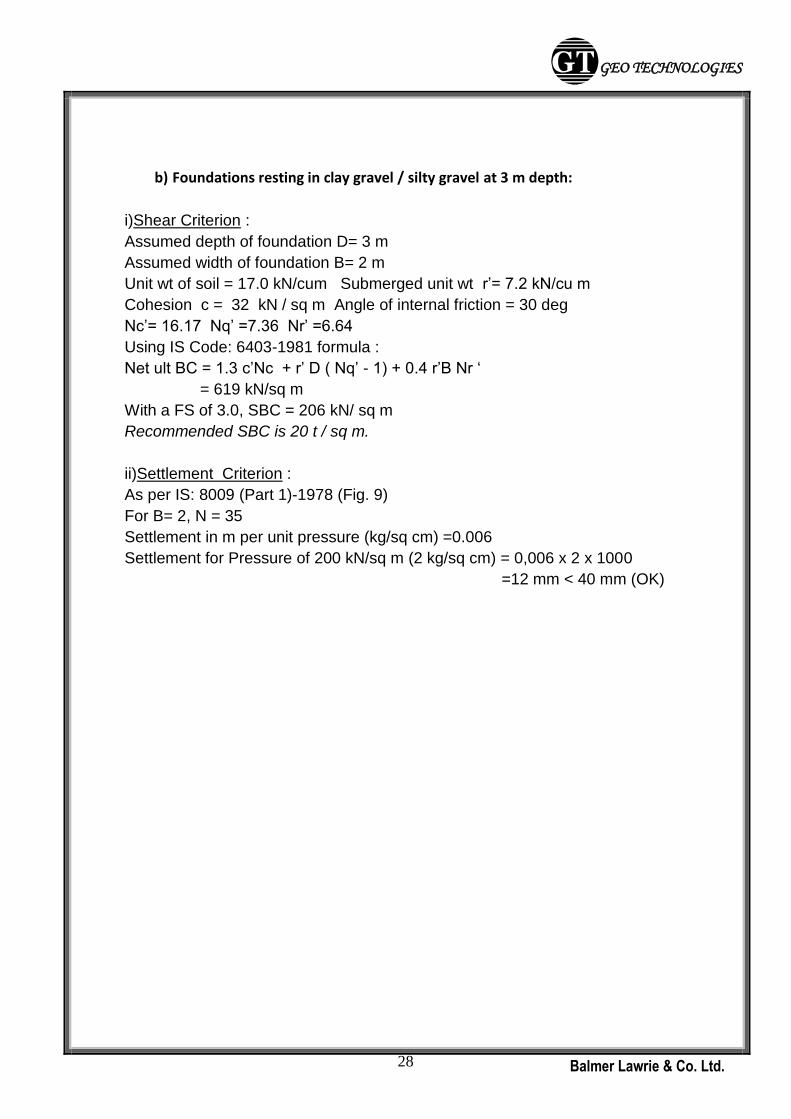
b) Foundations resting in clay gravel / silty gravel at 3 m depth:
i)Shear Criterion :
Assumed depth of foundation D= 3 m
Assumed width of foundation B= 2 m
Unit wt of soil = 17.0 kN/cum Submerged unit wt r’= 7.2 kN/cu m
Cohesion c = 32 kN / sq m Angle of internal friction = 30 deg
Nc’= 16.17 Nq’ =7.36 Nr’ =6.64
Using IS Code: 6403-1981 formula :
Net ult BC = 1.3 c’Nc + r’ D ( Nq’ - 1) + 0.4 r’B Nr ‘
= 619 kN/sq m
With a FS of 3.0, SBC = 206 kN/ sq m
Recommended SBC is 20 t / sq m.
ii)Settlement Criterion :
As per IS: 8009 (Part 1)-1978 (Fig. 9)
For B= 2, N = 35
Settlement in m per unit pressure (kg/sq cm) =0.006
Settlement for Pressure of 200 kN/sq m (2 kg/sq cm) = 0,006 x 2 x 1000
=12 mm < 40 mm (OK)
29
GEO TECHNOLOGIES
Balmer Lawrie & Co. Ltd.
Project: Soil Investigation for proposed Multi Modal Logistic Hub
at Visakhapatnam, Andhra Pradesh.
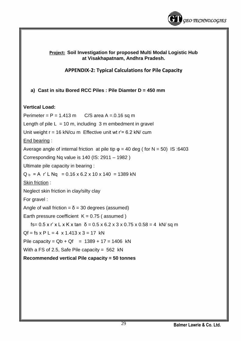
APPENDIX-2: Typical Calculations for Pile Capacity
a) Cast in situ Bored RCC Piles : Pile Diamter D = 450 mm
Vertical Load:
Perimeter = P = 1.413 m C/S area A =.0.16 sq m
Length of pile L = 10 m, including 3 m embedment in gravel
Unit weight r = 16 kN/cu m Effective unit wt r’= 6.2 kN/ cum
End bearing :
Average angle of internal friction at pile tip φ = 40 deg ( for N = 50) IS :6403
Corresponding Nq value is 140 (IS: 2911 – 1982 )
Ultimate pile capacity in bearing :
Q b = A r’ L Nq = 0.16 x 6.2 x 10 x 140 = 1389 kN
Skin friction :
Neglect skin friction in clay/silty clay
For gravel :
Angle of wall friction = δ = 30 degrees (assumed)
Earth pressure coefficient K = 0.75 ( assumed )
fs= 0.5 x r’ x L x K x tan δ = 0.5 x 6.2 x 3 x 0.75 x 0.58 = 4 kN/ sq m
Qf = fs x P L = 4 x 1.413 x 3 = 17 kN
Pile capacity = Qb + Qf = 1389 + 17 = 1406 kN
With a FS of 2.5, Safe Pile capacity = 562 kN
Recommended vertical Pile capacity = 50 tonnes
30
GEO TECHNOLOGIES
Balmer Lawrie & Co. Ltd.
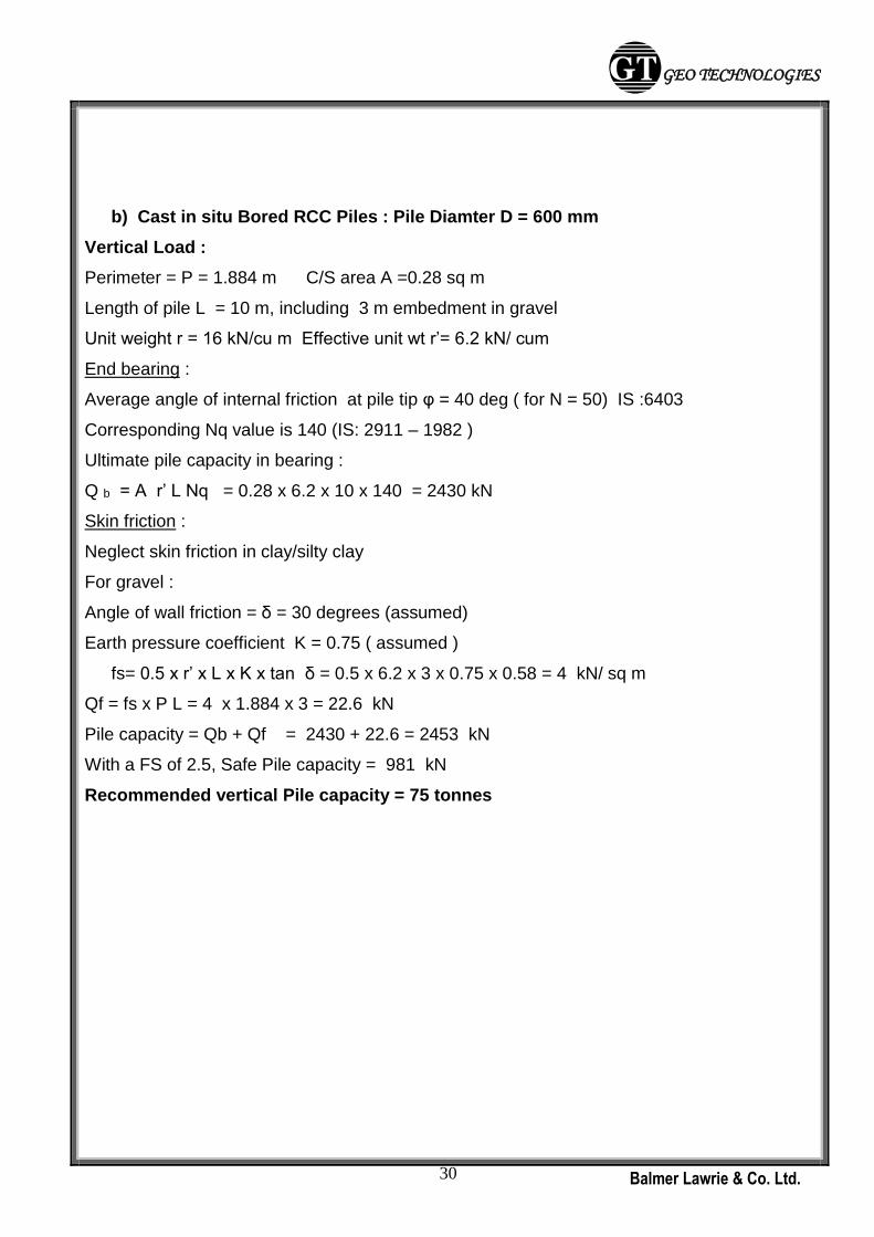
b) Cast in situ Bored RCC Piles : Pile Diamter D = 600 mm
Vertical Load :
Perimeter = P = 1.884 m C/S area A =0.28 sq m
Length of pile L = 10 m, including 3 m embedment in gravel
Unit weight r = 16 kN/cu m Effective unit wt r’= 6.2 kN/ cum
End bearing :
Average angle of internal friction at pile tip φ = 40 deg ( for N = 50) IS :6403
Corresponding Nq value is 140 (IS: 2911 – 1982 )
Ultimate pile capacity in bearing :
Q b = A r’ L Nq = 0.28 x 6.2 x 10 x 140 = 2430 kN
Skin friction :
Neglect skin friction in clay/silty clay
For gravel :
Angle of wall friction = δ = 30 degrees (assumed)
Earth pressure coefficient K = 0.75 ( assumed )
fs= 0.5 x r’ x L x K x tan δ = 0.5 x 6.2 x 3 x 0.75 x 0.58 = 4 kN/ sq m
Qf = fs x P L = 4 x 1.884 x 3 = 22.6 kN
Pile capacity = Qb + Qf = 2430 + 22.6 = 2453 kN
With a FS of 2.5, Safe Pile capacity = 981 kN
Recommended vertical Pile capacity = 75 tonnes
31
GEO TECHNOLOGIES
Balmer Lawrie & Co. Ltd.
Project: Soil Investigation for proposed Multi Modal Logistic Hub
at Visakhapatnam, Andhra Pradesh.
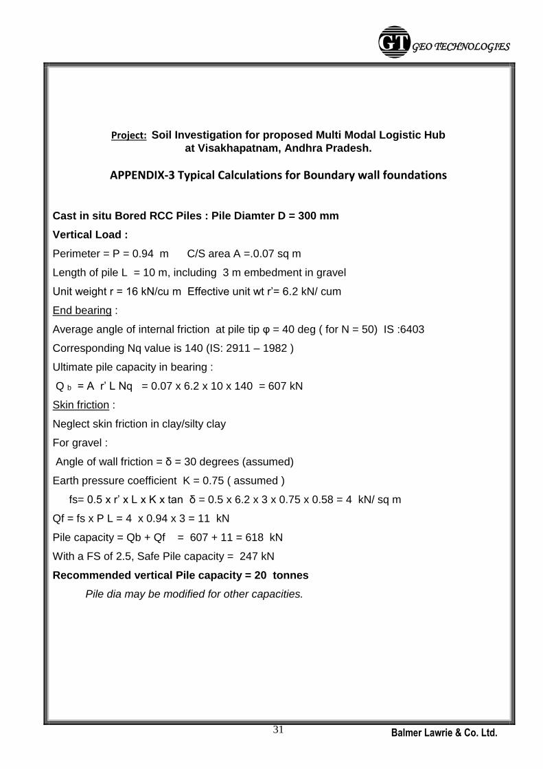
APPENDIX-3 Typical Calculations for Boundary wall foundations
Cast in situ Bored RCC Piles : Pile Diamter D = 300 mm
Vertical Load :
Perimeter = P = 0.94 m C/S area A =.0.07 sq m
Length of pile L = 10 m, including 3 m embedment in gravel
Unit weight r = 16 kN/cu m Effective unit wt r’= 6.2 kN/ cum
End bearing :
Average angle of internal friction at pile tip φ = 40 deg ( for N = 50) IS :6403
Corresponding Nq value is 140 (IS: 2911 – 1982 )
Ultimate pile capacity in bearing :
Q b = A r’ L Nq = 0.07 x 6.2 x 10 x 140 = 607 kN
Skin friction :
Neglect skin friction in clay/silty clay
For gravel :
Angle of wall friction = δ = 30 degrees (assumed)
Earth pressure coefficient K = 0.75 ( assumed )
fs= 0.5 x r’ x L x K x tan δ = 0.5 x 6.2 x 3 x 0.75 x 0.58 = 4 kN/ sq m
Qf = fs x P L = 4 x 0.94 x 3 = 11 kN
Pile capacity = Qb + Qf = 607 + 11 = 618 kN
With a FS of 2.5, Safe Pile capacity = 247 kN
Recommended vertical Pile capacity = 20 tonnes
Pile dia may be modified for other capacities.
32
GEO TECHNOLOGIES
Balmer Lawrie & Co. Ltd.
Annexure-1
FIELD BORE CHARTS
20
21
114
1
22
17
18
19
EXISTING COMPOUND WALL
EXISTING COMPOUND WALL
EXISTING COMPOUND WALL
EXISTING COMPOUND WALL
EXISTING COMPOUND WALL
WIGH BRIDGE
M/S SRAVAN SHIPPING
EXIS
TING
COM
POU
ND W
ALL
BU
ILD
ING
BUILDIN
G
BUILDIN
G
BUILDIN
G
BU
ILD
ING
SHED
SHED
FE
NC
ING
FE
NC
ING
PIP
E L
INE
PIPE
LINE
PIPE
LIN
E
PIP
E L
INE
CULVERT
PILLAR
PILLAR
PILLAR
PILLAR
PILLAR
PILLAR
PILLAR
PILLAR
PILLAR
PILLAR
GODOWN
M/S SRAVAN SHIPPING
GODOWN
WBM ROAD
HINDUSTA
N ZIN
C LTD.
GA
TE
MINDI VILLEGE
EXISTING COMPOUND WALL
M/S SRAVAN SHIPPING
GODOWN
ROAD
RO
AD
ROAD
CONTAINER STACK YARD(Ac 4.25 Cts)
(LICENSE TO
M/S SRAVAN SHIPPING)
1
2
3
4
5
6
7
8 9
10
11
12
13
14
15
1617
18
19
2021
2223
2425
GATE
MIN
DI
VIL
LA
GE
R O A D
PIP
E
CU
LV
ERT
CULVERT
CULVERT
CULVERT
Open Drain
Water Flow
Open Drain
Water Flow
Ope
n D
rain
W
ater
Flo
w
Ope
n D
rain
Wat
er F
low
Open D
rain
Wate
r Flow
Ope
n D
rain
Wat
er F
low
Ope
n D
rain
Wat
er F
low
STATION:- BLCL-1
E=736402.161
N=1959302.627
Z=7.121
VPT TBM-20
R.L:- 5.820
CULVERT
Ø90
0 HU
ME
PIPE
S
R.L : 9
.57
R.L : 9
.28
R.L : 8
.45
R.L : 8
.05
R.L : 7
.47
R.L : 7
.96
R.L : 8
.18
R.L : 8
R.L : 7
.92
R.L : 7
.96
R.L : 8
.4
R.L : 8
.16
R.L : 7
.67
R.L : 7
.72
R.L : 8
.36
R.L : 5
.67
R.L : 5
.92
R.L : 6
.23
R.L : 5
.83
R.L : 8
.85
R.L : 8
.11
R.L : 8
.97
R.L : 8
.36
R.L : 8
.66 R.L : 9
.2
R.L : 9
.27
R.L : 8
.87
R.L : 9
.5
R.L : 7
.28
R.L : 6
.74
R.L : 6
.98
R.L : 6
.45
R.L : 6
.51
R.L : 6
.07
R.L : 6
.29
R.L : 6
.75
HTL: 10.46
HTL: 10.54
HTL: 16.67
HTL: 16.69
HTL: 13.67
HTL: 13.77
HTL: 12.66
HTL: 17.17
HTL: 17.14
HTL: 16.15
HTL: 16.74
HTL: 13.96
HTL: 13.73
HTL: 13.46
HTL: 13.21
HTL: 12.51
HTL: 11.86
HTL: 17.17
HTL: 17.12
HTL: 14.05
RD: 7.17
RD: 7.27
RD: 7.22
RD: 6.99
RD: 8.27
RD: 6.82
RD: 7.02
RD: 7.04
RD: 6.79
RD: 6.47
RD: 6.71
RD: 6.72
RD: 6.51
RD: 6.13
RD: 6.35
RD: 6.35
RD: 6.09
RD: 6.19
RD: 6.41
RD: 6.43
RD: 6.19
RD: 5.83
RD: 6
.1
RD: 6.28
RD: 6
.11
RD: 5.71
RD: 6
RD: 5.89
RD: 6.12
RD: 5.14
RD: 5.09
RD: 5.59
RD: 5.54
RD: 5.52
RD: 5.76
RD: 5.26
RD: 5.56
RD: 6
.29
RD: 6.3
RD: 6.09
RD: 5.56
RD: 5.43
RD: 5.7
RD: 5.14
RD: 4.93
RD: 5.27
RD: 6.21
RD: 6.28
RD: 6.29
RD: 5.92
RD: 5.93
RD: 6
.06
RD: 6.01
RD: 6
.05 R
D: 6.06
RD: 6
.08
RD: 6
RD: 5.7
RD: 5.76
RD: 5.84
RD: 5.95
RD: 5.94
RD: 5.88
RD: 5.69
RD: 5.24
RD: 5.03
RD: 5
.3
RD: 5.44
RD: 5.37
RD: 5.83
RD: 4.35
RD: 5.83
RD: 4.45
RD: 5
.53
RD: 4.7
RD: 5.32
RD: 3.91
RD: 5
.19
RD: 5.57
RD: 5
.51
RD: 5.33
RD: 5.36
RD: 5.43
RD: 5
.45
RD: 5.67
RD: 5.4
RD: 6
.06
RD: 5.44
RD: 5.46
RD: 5.37
RD: 5.4
RD: 5.48
RD: 5.34
RD: 5.43
RD: 5.44
RD: 5.42
RD: 5.44
RD: 5.43
RD: 5.51
RD: 5.6
RD: 5.46
RD: 5.39
RD: 5.36
RD: 5.32
RD: 5.31
RD: 5.25
RD: 5.44
RD: 5.38
RD: 5.35
RD: 5.52
RD: 5
.48
RD: 4.71
RD: 5.5
RD: 5.62
RD: 5.58
RD: 5.9
RD: 5.68
RD: 5.94
RD: 6.04
RD: 6.35
RD: 6
.34
RD: 6.85
RD: 6
.7
RD: 7.51
RD: 7
.11
RD: 7
RD: 7.09
RD: 7.18
RD: 7.23
RD: 7.2
RD: 7.43
MIN
DI
VIL
LA
GE
CEMETERY
WELL
60.62 M66.57 M
176.
83 M
69.43 M
140.6
7 M
70.65 M
105.66 M
91.6
7 M
145.71 M
127.
49 M
151.98 M
58.6
8 M
101.
32 M
46.1
7 M
51.0
0 M
251.22 M
141.
50 M
167.60 M
152.04 M
120.18 M
72.3
2 M
7.68 M
93.6
1 M
136.97 M
176.
65 M
BH:-1E=735812.500N=1958787.500Z=5.31
B.H - 2 E=735837.562N=1958962.450Z=3.91
B.H :- 3E=735812.558
N=1959137.541Z= 4.45
B.H:- 4E=735962.539N=1959112.559Z= 4.25
B.H = 5E=736087.483
N=1959187.431Z= 4.41
B.H :- 7E=736337.511N=1959212.402Z= 6.55 B.H :- 8
E=736487.442N=1959187.459
Z=3.85
B.H :- 6E=736237.433N=1959112.548Z=3.85
B.H:-9E=735700.737N=1959100.880Z=5.56
DCPT-2E=735814.334
N=1959122.278Z=4.45
DCPT-3E=736075.451N=1959174.718Z=4.40
CBR:-2E=736071.641N=1959142.480Z=4.46
CBR:-1E=736367.558N=1959170.653Z=5.09
DCPT-4E=736495.211N=1959212.818Z=3.72
CBR-3E=735866.217N=1959041.708Z=3.70
DCPT-1E=735799.470N=1958740.845Z=6.49
FIG:1 SITE PLAN SHOWING THE LOCATIONS BORE HOLES, CBR & DCPT
Project: Soil Investigation for Proposed Multi Modal Logistic Hub at Visakhapatnam, Andhra Pradesh
BORE HOLES DYNAMIC CONE PENETRATION TEST CALIFORNIA BEARING RATIO
0.0mBH-1
0.0mBH-2
FIG:2 LOG OF BORE HOLESProject: Soil Investigation for Proposed Multi Modal Logistic Hub
NOT TO SCALE
WATER TABLE
2.2m
0.0mBH-4
12.0m
1.2mSilty clay
1.8m
15.0m
ClayeyGravel
1.5m
Silty clay
1.2m
15.0m
6.0m
BH-5
1.4m
10.0m
4.0m
Silty clay
6.0m
ClayeyGravel
11.5m
Gravel
SDR
2.0mClay
3.3mSilty clay
6.0m
12.0m
Gravel
SDR
2.0mClay
4.0m
Silty clay
SiltyGravel
10.0m
Gravel
SDR
1.0mSilty clay
5.2m
Clay
6.0mSiltyGravel
0.0mBH-3
1.2mSilty sand0.2m
17.6m
7.5m
3.4m
Clay
ClayeyGravel
11.4m
Gravel
14.6m
SDR
Rock
0.0mBH-6
1.0m Silty sand0.2m
17.8m
8.0m
5.6m
Clay
14.8m
SDR
ClayeyGravel
9.8m
Gravel
Rock
0.0mBH-7
5.4m
15.0m
0.0m
4.3m
Filling
5.8m
Silty sand
9.4m
Clay
12.0m
ClayeyGravel
13.2mGravel
SDR
0.0mBH-8
1.6mSilty sand
0.0m
8.0m
6.5m
14.0m
10.6m
Gravel
Clay
ClayeyGravel
SDR
BH-9
0.0m
10.0m
6.0m
SDR
0.0m
1.2mSilty sand
3.7m
Clay
ClayeyGravel
6.7mGravel
GL=005.31
GL=003.91
GL=004.45GL=004.25 GL=004.41
GL=003.85
GL=006.55
GL=003.552m N=5
4m N=12
6m N=38
8m N=56
10m N=86
12m N=>100
2m N=5
4m N=25
6m N=51
8m N=68
10m N=81
12m N=88
14m N=>100
2m N=5
4m N=34
6m N=45
8m N=57
10m N=70
12m N=87
14m N=>100
2m N=3
4m N=47
6m N=49
8m N=65
10m N=73
12m N=91
14m N=>100
2m N=3
4m N=4
6m N=91
8m N=94
9m N=>100
5.2m N=51
9.0m
SDR
Rock
2m N=4
4m N=7
6m N=29
8m N=56
10m N=95
12m N=96
14m N=>100
2m N=8
4m N=7
6m N=5
8m N=7
10m N=50
12m N=85
14m N=>100
5m N=4 2m N=2
4m N=3
6m N=5
8m N=31
10m N=60
12m N=94
14m N=>100
2m N=4
4m N=29
6m N=47
7m N=85
9m N=>100
Rock
9.0m
14.0mRock N= value
GL=005.56
at Visakhapatnam, Andhra Pradesh
Depth TypeNo. blows for
Penetration ofN >10cm core Total No. of % of core
From To (m) (15-30-45)cm Value Pieces(cm)Length
(cm)Pieces Recovery
1.00 D/S
2.00 SPT 2-2-3 5
3.00 UDS
4.00 SPT 4-6-6 12
5.00 D/S
6.00 SPT 9-18-20 38
7.00 D/S
8.00 SPT 13-22-34 56
9.00 D/S
10.00 SPT 26-37-49 86
11.00 D/S
12.00 SPT 17cm/50blows >50
yellow
yellow
Clayey
Gravel
yellowGravel
6.0 8.0 2.0
Red
8.0 10.0 2.0
yellow5.0
1.0
0.0 1.0 1.0
Silty clay
2.0
1.0 2.0
5.0 1.0
4.0
6.0
Red
10.0 11.5
4.0
yellow
yellow
yellow
1.5
2.0
1.0
SDR=Soft Disintigrated Rock cm/50= no.of blows sp=Small pieces vsp=Very Small Pieces
11.5 12.0 0.5 SDR
Avg.
RQD
%
Water
colour
Rate of
Drill
Min/m
Details of Rock core
RQD
Value
%
Depth SPT
Length
of
Run
(m)
DescriptionLog of
Bore
(m)
Sampling
GEO TECHNOLOGIES
FIELD BORE LOG CHART
BORE HOLE
NO. 1
Ground Level: Dia. Of Casing: NX
Water Table: 2.20m
Project: Soil Investigation for proposed Multi Modal Logistic Hub
at Visakhapatnam, Andhra Pradesh.
Depth TypeNo. blows for
Penetration ofN >10cm core Total No. of % of core
From To (m) (15-30-45)cm Value Pieces(cm)Length
(cm)Pieces Recovery
1.00 D/S
2.00 SPT 2-2-3 5
3.00 UDS
4.00 SPT 8-11-14 25
5.00 D/S
6.00 SPT 12-19-32 51
7.00 D/S
8.00 SPT 18-31-37 68
10.00 SPT 21-38-43 81
11.00 D/S
12.00 SPT 30-40-48 88
13.00 D/S
14.00 SPT 16cm/100blows >100
Reddish
SDR
Rock 11+13=24
Reddish
0.0 1.2 1.2 Silty clay
10.0
12.0
Milky15.0 481.014.0
14.0 2.0 Yellow
SDR=Soft Disintigrated Rock cm/50= no.of blows sp=Small pieces vsp=Very Small Pieces
2no+6
sp48% 24%
Yellow
Yellow
Yellow
8.0 10.0 2.0
12.0
6.0 2.0
2.0
Gravel
6.0 8.0 2.0
Clayey
Gravel4.0
Yellow
Yellow
2.0 3.3 1.3 Silty clay
3.3 4.0 0.7
1.2 2.0 0.8 Clay
Details of Rock core
RQD
Value
%
Avg.
RQD
%
Water
colour
Rate of
Drill
Min/m
Reddish
Depth
Length
of
Run
(m)
DescriptionLog of
Bore
Sampling SPT
(m)
GEO TECHNOLOGIES
FIELD BORE LOG CHART
BORE HOLE
NO. 2
Ground Level: Dia. Of Casing: NX
Water Table: 1.80m
Project: Soil Investigation for proposed Multi Modal Logistic Hub
at Visakhapatnam, Andhra Pradesh.
Depth TypeNo. blows for
Penetration ofN >10cm core Total No. of % of core
From To (m) (15-30-45)cm Value Pieces(cm)Length
(cm)Pieces Recovery
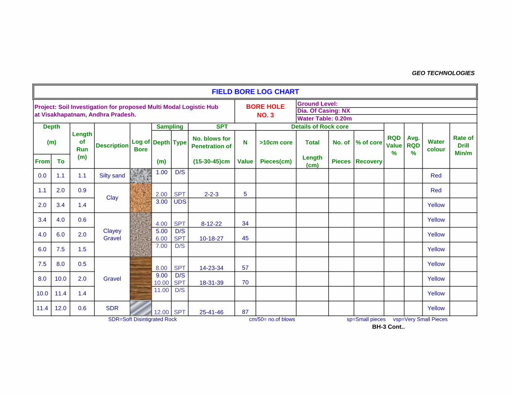
1.00 D/S
2.00 SPT 2-2-3 5
3.00 UDS
4.00 SPT 8-12-22 34
5.00 D/S
6.00 SPT 10-18-27 45
7.00 D/S
8.00 SPT 14-23-34 57
9.00 D/S
10.00 SPT 18-31-39 70
11.00 D/S
12.00 SPT 25-41-46 87
BH-3 Cont..
Yellow
SDR=Soft Disintigrated Rock cm/50= no.of blows sp=Small pieces vsp=Very Small Pieces
Clay
Clayey
Gravel
SDR
Gravel
11.4 12.0 0.6
Yellow
Yellow
10.0 11.4 1.4
Yellow
8.0 10.0 2.0
Yellow
7.5 8.0 0.5
6.0 7.5 1.5
Yellow
Yellow3.4 4.0 0.6
4.0 6.0 2.0
Yellow2.0 3.4 1.4
Red 1.1 2.0 0.9
Red 0.0 1.1 1.1 Silty sand
Details of Rock core
RQD
Value
%
Avg.
RQD
%
Water
colour
Rate of
Drill
Min/m
Depth
Length
of
Run
(m)
DescriptionLog of
Bore
Sampling SPT
(m)
GEO TECHNOLOGIES
FIELD BORE LOG CHART
BORE HOLE
NO. 3
Ground Level: Dia. Of Casing: NX
Water Table: 0.20m
Project: Soil Investigation for proposed Multi Modal Logistic Hub
at Visakhapatnam, Andhra Pradesh.
Depth TypeNo. blows for
Penetration ofN >10cm core Total No. of % of core
From To (m) (15-30-45)cm Value Pieces(cm)Length
(cm)Pieces Recovery
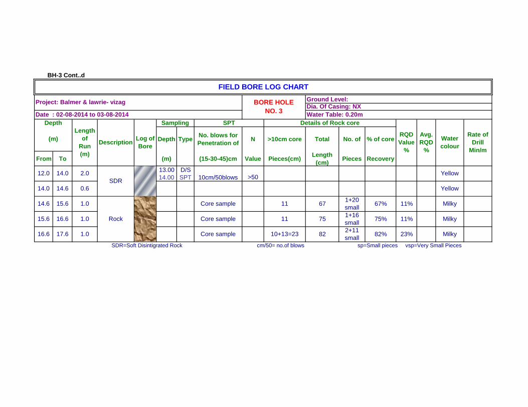
13.00 D/S
14.00 SPT 10cm/50blows >50
Core sample
Core sample
Core sample
SDR=Soft Disintigrated Rock cm/50= no.of blows sp=Small pieces vsp=Very Small Pieces
82% 23% Milky
11% Milky
16.6 17.6 1.0 10+13=23 822+11
small
Milky
15.6 16.6 1.0 11 751+16
small75%
14.6 15.6 1.0
Rock
11 671+20
small67% 11%
Yellow
Yellow12.0 14.0 2.0
SDR
14.0 14.6 0.6
RQD
Value
%
Avg.
RQD
%
Water
colour
Rate of
Drill
Min/m
(m)
Depth
Length
of
Run
(m)
DescriptionLog of
Bore
BH-3 Cont..d
FIELD BORE LOG CHART
Project: Balmer & lawrie- vizag BORE HOLE
NO. 3
Ground Level: Dia. Of Casing: NX
Date : 02-08-2014 to 03-08-2014 Water Table: 0.20m
Sampling SPT Details of Rock core
Depth TypeNo. blows for
Penetration ofN >10cm core Total No. of % of core
From To (m) (15-30-45)cm Value Pieces(cm)Length
(cm)Pieces Recovery
1.00 D/S
2.00 SPT 1-1-2 3
3.00 UDS
4.00 SPT 14-18-29 47
5.00 D/S
6.00 SPT 13-19-30 49
8.00 SPT 21-29-36 65
9.00 D/S
10.00 SPT 25-32-41 73
11.00 D/S
12.00 SPT 31-40-51 91
14.00 SPT 10cm/100blows >100
15.00 D/S
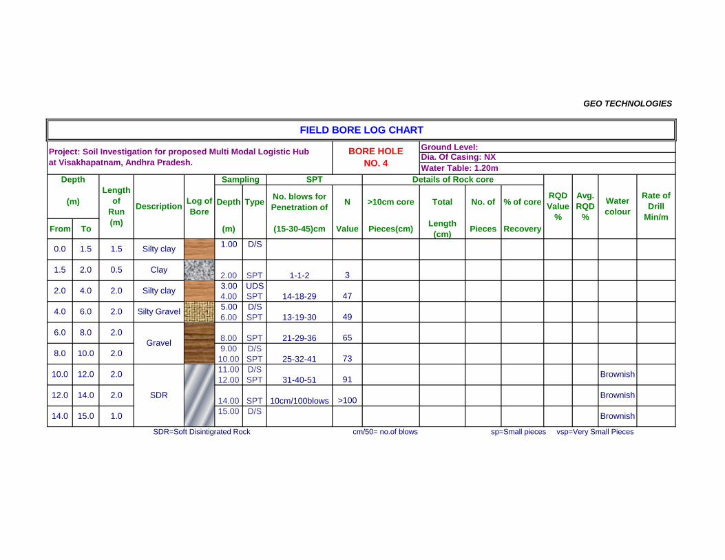
0.0 1.5 1.5 Silty clay
SDR=Soft Disintigrated Rock cm/50= no.of blows sp=Small pieces vsp=Very Small Pieces
Brownish14.0 15.0
Brownish12.0 14.0 2.0 SDR
1.0
10.0 12.0 2.0 Brownish
8.0 10.0 2.0
4.0 6.0 2.0
6.0 8.0 2.0
Silty Gravel
Gravel
2.0 4.0 2.0 Silty clay
1.5 2.0 0.5 Clay
Details of Rock core
RQD
Value
%
Avg.
RQD
%
Water
colour
Rate of
Drill
Min/m
Depth
Length
of
Run
(m)
DescriptionLog of
Bore
Sampling SPT
(m)
GEO TECHNOLOGIES
FIELD BORE LOG CHART
BORE HOLE
NO. 4
Ground Level: Dia. Of Casing: NX
Water Table: 1.20m
Project: Soil Investigation for proposed Multi Modal Logistic Hub
at Visakhapatnam, Andhra Pradesh.
Depth TypeNo. blows for
Penetration ofN >10cm core Total No. of % of core
From To (m) (15-30-45)cm Value Pieces(cm)Length
(cm)Pieces Recovery
1.00 D/S
2.00 SPT 1-1-2 3
3.00 UDS
4.00 SPT 1-2-2 4
5.00 D/S
5.20 SPT 14-19-32 51
6.00 SPT 32-40-51 91
7.00 D/S
8.00 SPT 38-41-53 94
9.00 SPT 12cm/100blows >100
SDR
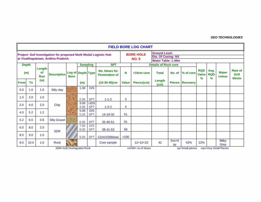
Rock Core sample 22%
SDR=Soft Disintigrated Rock cm/50= no.of blows sp=Small pieces vsp=Very Small Pieces
9.0 10.0 1.0 12+10=22 422no+5
sp42%
Milky
Grey
8.0 9.0 1.0
6.0 8.0 2.0
5.2 6.0 0.8 Silty Gravel
4.0 Clay
2.0 1.0
2.0
1.0
2.0
4.0 5.2 1.2
0.0 1.0 1.0 Silty clay
RQD
Value
%
Avg.
RQD
%
Water
colour
Rate of
Drill
Min/m
Depth
Length
of
Run
(m)
DescriptionLog of
Bore
Sampling SPT
(m)
Details of Rock core
GEO TECHNOLOGIES
FIELD BORE LOG CHART
BORE HOLE
NO. 5
Ground Level: Dia. Of Casing: NX
Water Table: 1.40m
Project: Soil Investigation for proposed Multi Modal Logistic Hub
at Visakhapatnam, Andhra Pradesh.
Depth TypeNo. blows for
Penetration ofN >10cm core Total No. of % of core
From To (m) (15-30-45)cm Value Pieces(cm)Length
(cm)Pieces Recovery
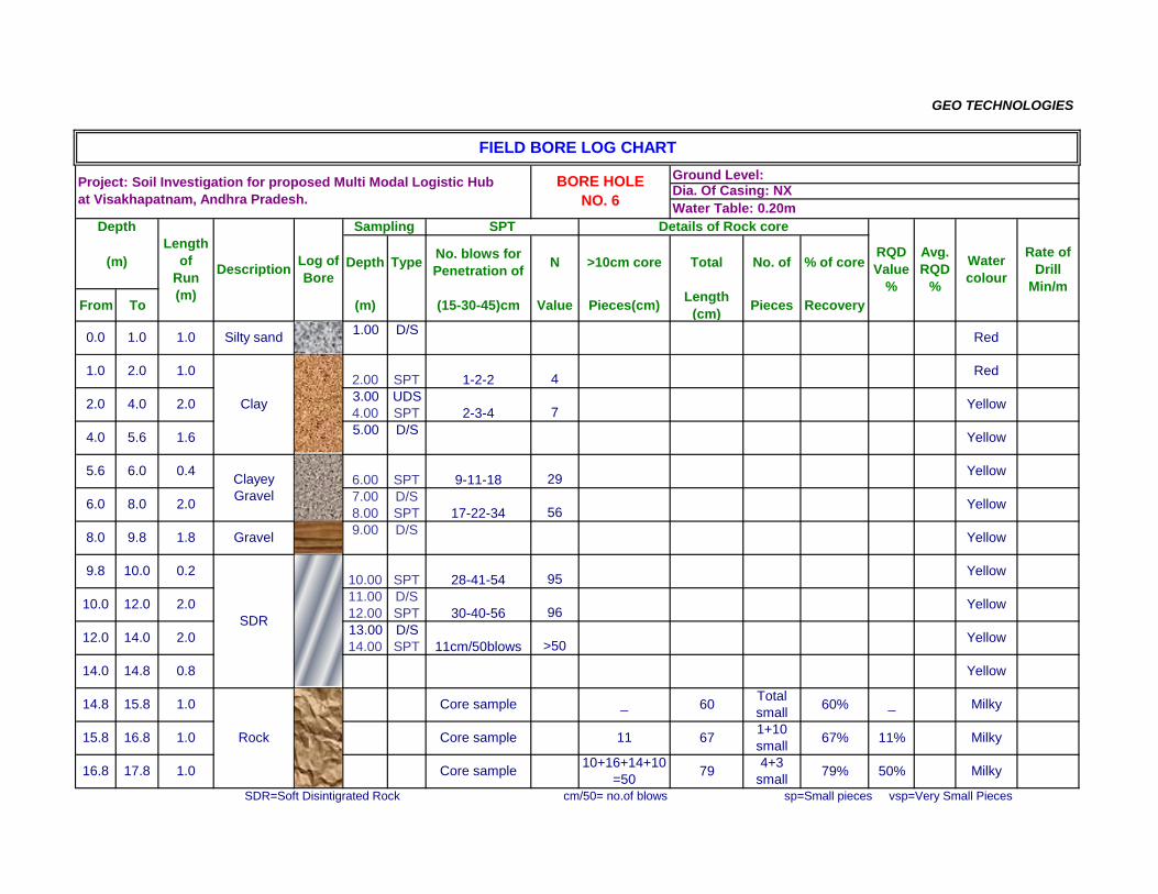
1.00 D/S
2.00 SPT 1-2-2 4
3.00 UDS
4.00 SPT 2-3-4 7
5.00 D/S
6.00 SPT 9-11-18 29
7.00 D/S
8.00 SPT 17-22-34 56
9.00 D/S
10.00 SPT 28-41-54 95
11.00 D/S
12.00 SPT 30-40-56 96
13.00 D/S
14.00 SPT 11cm/50blows >50
Clay
Clayey
Gravel
Gravel
SDR
Rock
Core sample
Core sample
Core sample
Yellow
Yellow
12.0 14.0 2.0
Yellow
10.0 12.0 2.0
9.8 1.8 Yellow
9.8 10.0 0.2
8.0
79% 50%
67% 11%
SDR=Soft Disintigrated Rock cm/50= no.of blows sp=Small pieces vsp=Very Small Pieces
Milky
16.8 17.8 1.010+16+14+10
=5079
15.8 16.8 1.0 11 671+10
small
60% _
4+3
small
Milky
Milky
14.8 15.8 1.0 _ 60Total
small
Yellow
Yellow
14.0 14.8 0.8
Yellow
6.0 8.0 2.0
Yellow
5.6 6.0 0.4
4.0 5.6 1.6
Yellow
Red 1.0 2.0 1.0
2.0 4.0 2.0
Red 0.0 1.0 1.0 Silty sand
Details of Rock core
RQD
Value
%
Avg.
RQD
%
Water
colour
Rate of
Drill
Min/m
Depth
Length
of
Run
(m)
DescriptionLog of
Bore
Sampling SPT
(m)
GEO TECHNOLOGIES
FIELD BORE LOG CHART
BORE HOLE
NO. 6
Ground Level: Dia. Of Casing: NX
Water Table: 0.20m
Project: Soil Investigation for proposed Multi Modal Logistic Hub
at Visakhapatnam, Andhra Pradesh.
Depth TypeNo. blows for
Penetration ofN >10cm core Total No. of % of core
From To (m) (15-30-45)cm Value Pieces(cm)Length
(cm)Pieces Recovery
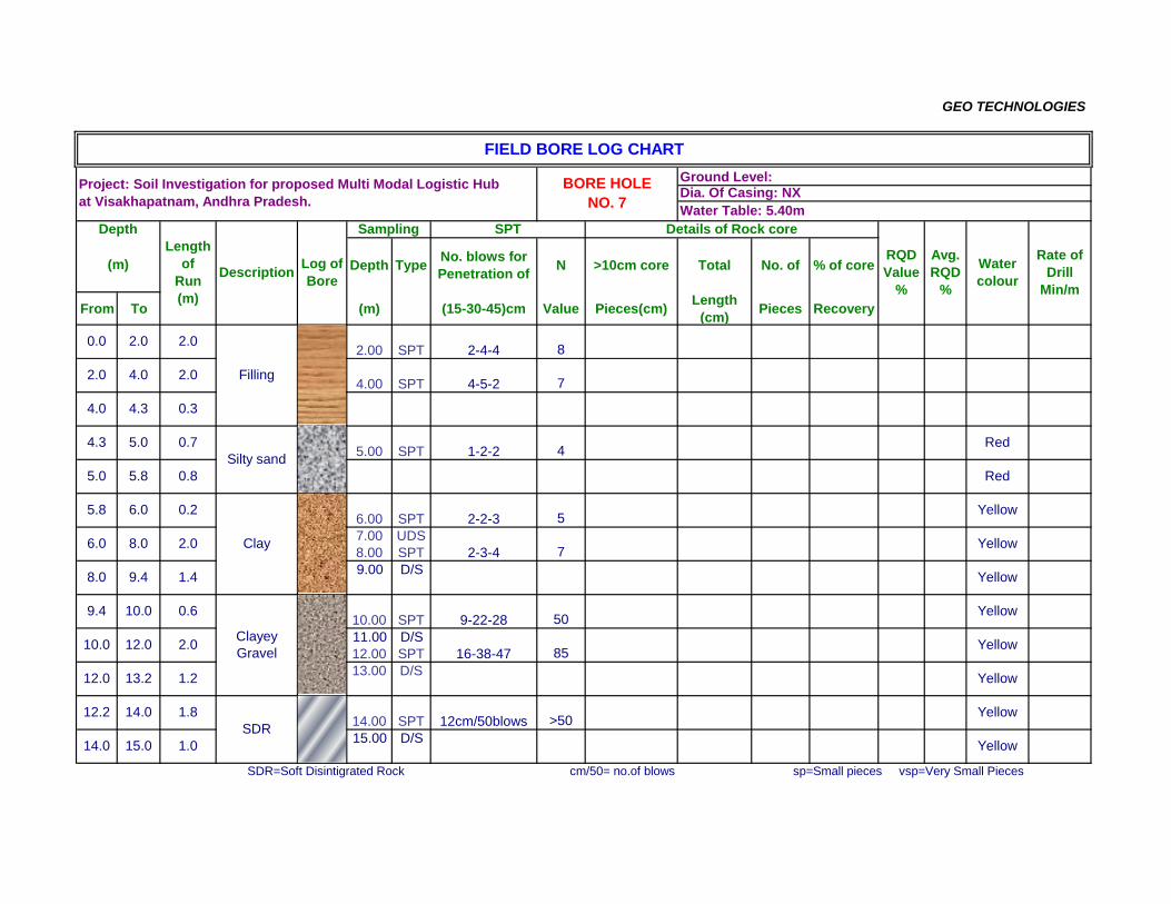
2.00 SPT 2-4-4 8
4.00 SPT 4-5-2 7
5.00 SPT 1-2-2 4
6.00 SPT 2-2-3 5
7.00 UDS
8.00 SPT 2-3-4 7
9.00 D/S
10.00 SPT 9-22-28 50
11.00 D/S
12.00 SPT 16-38-47 85
13.00 D/S
14.00 SPT 12cm/50blows >50
15.00 D/S
Silty sand
Clay
Clayey
Gravel
SDR=Soft Disintigrated Rock cm/50= no.of blows sp=Small pieces vsp=Very Small Pieces
Yellow14.0 15.0 1.0
Yellow
Yellow
12.2 14.0 1.8
SDR
10.0 12.0 2.0
12.0 13.2 1.2
Yellow
Yellow
Yellow
9.4 10.0 0.6
8.0 9.4 1.4
Yellow
6.0 8.0 2.0 Yellow
Red
5.8 6.0 0.2
Red
5.0 5.8 0.8
4.3 5.0 0.7
4.0 4.3 0.3
0.0 2.0 2.0
Filling2.0 4.0 2.0
Details of Rock core
RQD
Value
%
Avg.
RQD
%
Water
colour
Rate of
Drill
Min/m
Depth
Length
of
Run
(m)
DescriptionLog of
Bore
Sampling SPT
(m)
GEO TECHNOLOGIES
FIELD BORE LOG CHART
BORE HOLE
NO. 7
Ground Level: Dia. Of Casing: NX
Water Table: 5.40m
Project: Soil Investigation for proposed Multi Modal Logistic Hub
at Visakhapatnam, Andhra Pradesh.
Depth TypeNo. blows for
Penetration ofN >10cm core Total No. of % of core
From To (m) (15-30-45)cm Value Pieces(cm)Length
(cm)Pieces Recovery
1.00 D/S
2.00 SPT 1-1-1 2
3.00 UDS
4.00 SPT 1-1-2 3
5.00 D/S
6.00 SPT 1-2-3 5
7.00 D/S
8.00 SPT 8-13-18 31
9.00 D/S
10.00 SPT 13-26-34 60
11.00 D/S
12.00 SPT 27-45-49 94
13.00 D/S
14.00 SPT 13cm/50blows >50
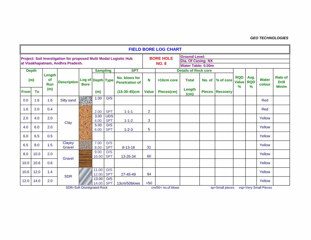
GEO TECHNOLOGIES
FIELD BORE LOG CHART
BORE HOLE
NO. 8
Ground Level: Dia. Of Casing: NX
Water Table: 0.00m
Project: Soil Investigation for proposed Multi Modal Logistic Hub
at Visakhapatnam, Andhra Pradesh.
Depth
Length
of
Run
(m)
DescriptionLog of
Bore
Sampling SPT
(m)
Details of Rock core
RQD
Value
%
Avg.
RQD
%
Water
colour
Rate of
Drill
Min/m
0.0 1.6 1.6 Silty sand Red
1.6 2.0 0.4
2.0 4.0 2.0 Yellow
Red
2.0
6.0 6.5 0.5
4.0
8.0 1.5Clayey
Gravel
Clay
6.0 Yellow
8.0 10.0 2.0
Yellow
6.5
Yellow
Yellow
10.0 10.6 0.6 Yellow
10.6 12.0 1.4
12.0 14.0 2.0
SDR
Gravel
SDR=Soft Disintigrated Rock cm/50= no.of blows sp=Small pieces vsp=Very Small Pieces
Yellow
Yellow
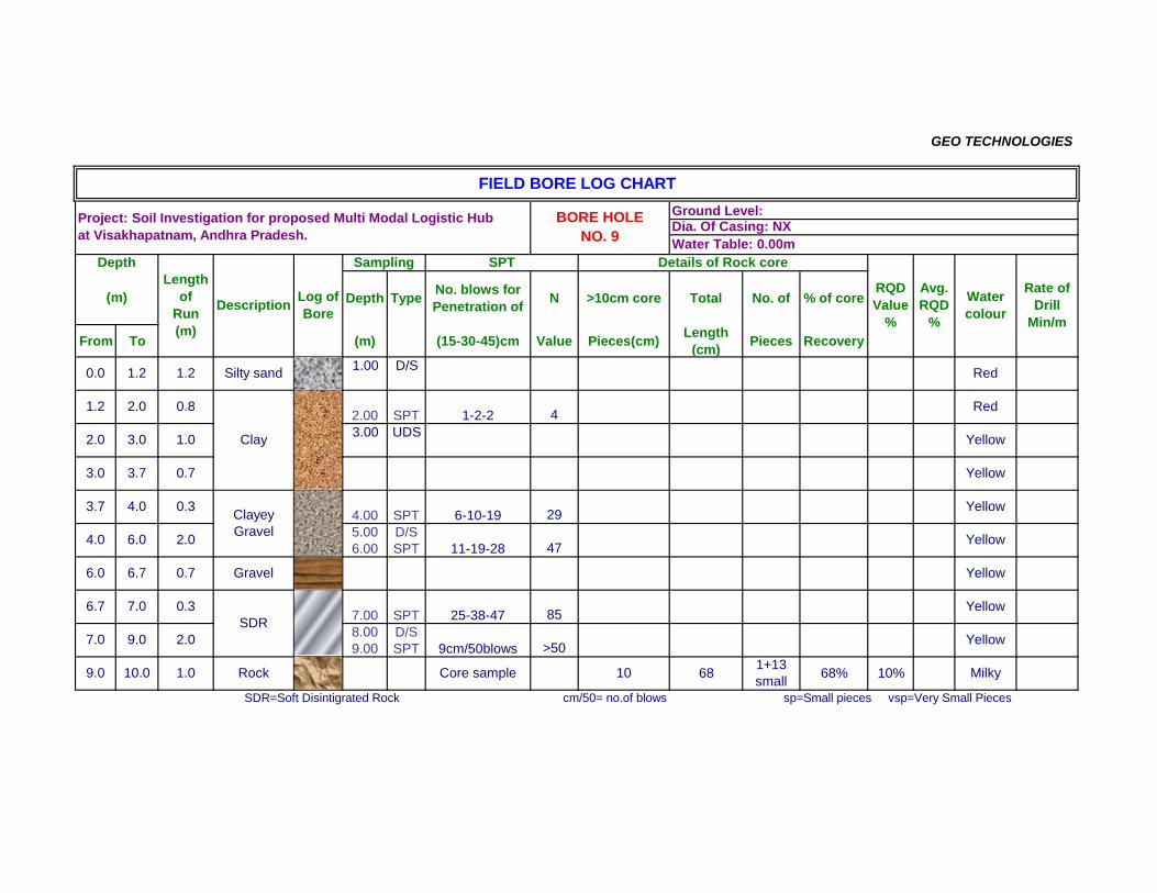
Depth TypeNo. blows for
Penetration ofN >10cm core Total No. of % of core
From To (m) (15-30-45)cm Value Pieces(cm)Length
(cm)Pieces Recovery
1.00 D/S
2.00 SPT 1-2-2 4
3.00 UDS
4.00 SPT 6-10-19 29
5.00 D/S
6.00 SPT 11-19-28 47
7.00 SPT 25-38-47 85
8.00 D/S
9.00 SPT 9cm/50blows >50
GEO TECHNOLOGIES
FIELD BORE LOG CHART
BORE HOLE
NO. 9
Ground Level: Dia. Of Casing: NX
Water Table: 0.00m
Project: Soil Investigation for proposed Multi Modal Logistic Hub
at Visakhapatnam, Andhra Pradesh.
Depth
Length
of
Run
(m)
DescriptionLog of
Bore
Sampling SPT
(m)
Details of Rock core
RQD
Value
%
Avg.
RQD
%
Water
colour
Rate of
Drill
Min/m
Red 0.0 1.2 1.2 Silty sand
1.0
1.2 2.0 0.8
Clay2.0 3.0 Yellow
Red
3.0 3.7 0.7
3.7 4.0 0.3Clayey
Gravel4.0 6.0
Yellow
Yellow
Yellow2.0
Gravel6.0 6.7 0.7
7.0 0.3
Yellow
7.0 9.0 2.0
6.7 Yellow
Rock 10% Milky9.0 10.0 1.01+13
small
SDR
10 68
SDR=Soft Disintigrated Rock cm/50= no.of blows sp=Small pieces vsp=Very Small Pieces
Yellow
Core sample 68%
GEO TECHNOLOGIES
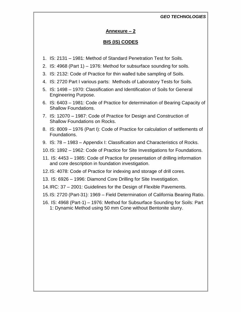
Annexure – 2
BIS (IS) CODES
1. IS: 2131 – 1981: Method of Standard Penetration Test for Soils.
2. IS: 4968 (Part 1) – 1976: Method for subsurface sounding for soils.
3. IS: 2132: Code of Practice for thin walled tube sampling of Soils.
4. IS: 2720 Part I various parts: Methods of Laboratory Tests for Soils.
5. IS: 1498 – 1970: Classification and Identification of Soils for General Engineering Purpose.
6. IS: 6403 – 1981: Code of Practice for determination of Bearing Capacity of Shallow Foundations.
7. IS: 12070 – 1987: Code of Practice for Design and Construction of Shallow Foundations on Rocks.
8. IS: 8009 – 1976 (Part I): Code of Practice for calculation of settlements of Foundations.
9. IS: 78 – 1983 – Appendix I: Classification and Characteristics of Rocks.
10. IS: 1892 – 1962: Code of Practice for Site Investigations for Foundations.
11. IS: 4453 – 1985: Code of Practice for presentation of drilling information and core description in foundation investigation.
12. IS: 4078: Code of Practice for indexing and storage of drill cores.
13. IS: 6926 – 1996: Diamond Core Drilling for Site Investigation.
14. IRC: 37 – 2001: Guidelines for the Design of Flexible Pavements.
15. IS: 2720 (Part-31): 1969 – Field Determination of California Bearing Ratio.
16. IS: 4968 (Part-1) – 1976: Method for Subsurface Sounding for Soils: Part 1: Dynamic Method using 50 mm Cone without Bentonite slurry.