project no. m1504-00 state of new jersey sow/m1504-00 steam and... · 2016-12-27 · project no....
TRANSCRIPT

Document Format Revision (9-21-16)
SCOPE OF WORK
STEAM & CONDENSATE LINE REPLACEMENT
Woodbine Developmental Center Woodbine, Cape May County, N.J.
PROJECT NO. M1504-00
STATE OF NEW JERSEY
Honorable Chris Christie, Governor Honorable Kim Guadagno, Lt. Governor
DEPARTMENT OF THE TREASURY Ford M. Scudder, Treasurer
DIVISION OF PROPERTY MANAGEMENT AND CONSTRUCTION
Christopher Chianese, Director
Date: Final 11/21 /16

PROJECT NAME: Steam & Condensate Piping Replacement PROJECT LOCATION: Woodbine Developmental Center PROJECT NO: M1504-00 DATE: 11/18/16
PAGE 2
TABLE OF CONTENTS SECTION PAGE
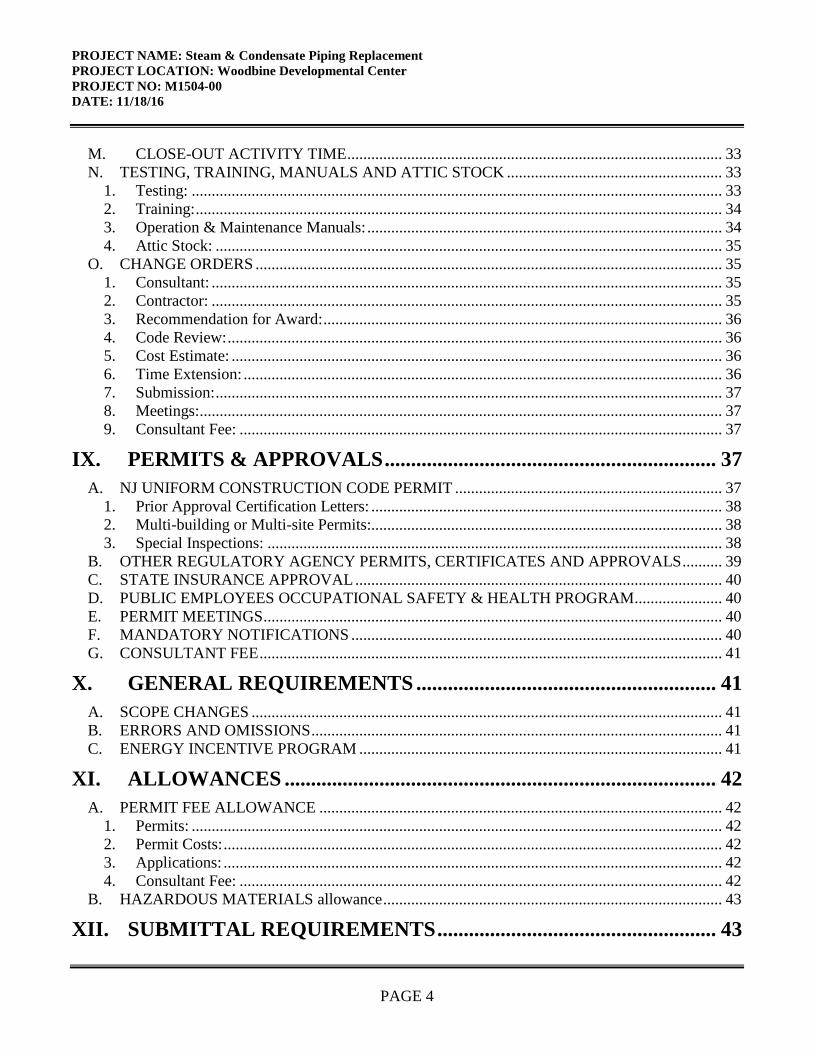
I. OBJECTIVE .......................................................................................... 6
II. CONSULTANT QUALIFICATIONS ................................................ 6
A. CONSULTANT & SUB-CONSULTANT PRE-QUALIFICATIONS ........................................... 6
III. PROJECT BUDGET ............................................................................ 6
A. CONSTRUCTION COST ESTIMATE (CCE) .............................................................................. 6 B. CURRENT WORKING ESTIMATE (CWE) ................................................................................ 6 C. CONSULTANT’S FEES ................................................................................................................ 7
IV. PROJECT SCHEDULE ....................................................................... 7
A. SCOPE OF WORK DESIGN & CONSTRUCTION SCHEDULE ............................................... 7 B. CONSULTANT’S PROPOSED DESIGN & CONSTRUCTION SCHEDULE ........................... 8 C. CONSULTANT DESIGN SCHEDULE ........................................................................................ 8 D. BID DOCUMENT CONSTRUCTION SCHEDULE .................................................................... 8 E. CONTRACTOR CONSTRUCTION PROGRESS SCHEDULE .................................................. 9
V. PROJECT SITE LOCATION & TEAM MEMBERS ...................... 9
A. PROJECT SITE ADDRESS ........................................................................................................... 9 B. PROJECT TEAM MEMBER DIRECTORY ............................................................................... 10
1. DPMC Representative: ............................................................................................................. 10 2. Client Agency Representative: ................................................................................................. 10
VI. PROJECT DEFINITION ................................................................... 10
A. BACKGROUND .......................................................................................................................... 10 B. FUNCTIONAL DESCRIPTION OF THE BUILDING ............................................................... 11
Building Description: ........................................................................................................................ 11 1. Cottages 15, 16, 17 & 18 / Long Term Care Unit: ................................................................... 11
C. DESCRIPTION OF THE STEAM AND CONDENSATE LINE SYSTEM ............................... 11
VII. CONSULTANT DESIGN RESPONSIBILITIES ........................... 12
A. GENERAL DESIGN OVERVIEW ........................................................................................... 12 1. Design Detail: ........................................................................................................................... 12 2. Specification Format: ................................................................................................................ 12 3. Submittal Schedule: .................................................................................................................. 13 4. Construction Cost Estimates: .................................................................................................... 13
B. BUILDING & SITE INFORMATION ......................................................................................... 13

PROJECT NAME: Steam & Condensate Piping Replacement PROJECT LOCATION: Woodbine Developmental Center PROJECT NO: M1504-00 DATE: 11/18/16
PAGE 3
1. Building Classification: ............................................................................................................ 14 2. Building Block & Lot Number: ................................................................................................ 14 3. Building Site Plan: .................................................................................................................... 14 4. Site Location Map: .................................................................................................................... 14
C. DESIGN MEETINGS & PRESENTATIONS.............................................................................. 14 1. Design Meetings: ...................................................................................................................... 14
D. STEAMLINE DISTRIBUTION SYSTEM SURVEYS ............................................................. 15 E. sTEAM & cONDENSATE LINE DESIGN CRITERIA ............................................................ 17 F. ASBESTOS............................................................................................................................. 22 G. PROJECT COMMENCEMENT .................................................................................................. 24
1. Project Directory: ...................................................................................................................... 24 2. Site Access: ............................................................................................................................... 25 3. Project Coordination: ................................................................................................................ 25 4. Existing Documentation: .......................................................................................................... 25 5. Scope of Work: ......................................................................................................................... 25 6. Project Schedule: ...................................................................................................................... 26
H. Construction Bid Document Submittal ......................................................................................... 26
VIII. CONSULTANT CONSTRUCTION RESPONSIBILITIES .......... 26
A. GENERAL CONSTRUCTION ADMINISTRATION OVERVIEW .......................................... 26 B. PRE-BID MEETING .................................................................................................................... 26 C. BID OPENING ............................................................................................................................. 26 D. POST BID REVIEW MEETING, RECOMMENDATION FOR AWARD ................................ 27
1. Post Bid Review:....................................................................................................................... 27 2. Review Meeting: ....................................................................................................................... 27 3. Substitutions:............................................................................................................................. 27 4. Schedule: ................................................................................................................................... 28 5. Performance: ............................................................................................................................. 28 6. Letter of Recommendation: ...................................................................................................... 28 7. Conformed Drawings: ............................................................................................................... 29
E. DIRECTOR’S HEARING ............................................................................................................ 29 F. CONSTRUCTION JOB MEETINGS, SCHEDULES, LOGS ..................................................... 29
1. Meetings:................................................................................................................................... 29 2. Schedules: ................................................................................................................................. 30 3. Submittal Log: .......................................................................................................................... 30
G. CONSTRUCTION SITE ADMINISTRATION SERVICES ....................................................... 30 H. SUB-CONSULTANT PARTICIPATION.................................................................................... 31 I. DRAWINGS ................................................................................................................................. 31
1. Shop Drawings: ......................................................................................................................... 31 2. As-Built & Record Set Drawings: ............................................................................................ 32
J. CONSTRUCTION DEFICIENCY LIST ..................................................................................... 32 K. INSPECTIONS: SUBSTANTIAL & FINAL COMPLETION .................................................... 33 L. CLOSE-OUT DOCUMENTS ...................................................................................................... 33
PROJECT NAME: Steam & Condensate Piping Replacement PROJECT LOCATION: Woodbine Developmental Center PROJECT NO: M1504-00 DATE: 11/18/16
PAGE 4
M. CLOSE-OUT ACTIVITY TIME .............................................................................................. 33 N. TESTING, TRAINING, MANUALS AND ATTIC STOCK ...................................................... 33
1. Testing: ..................................................................................................................................... 33 2. Training: .................................................................................................................................... 34 3. Operation & Maintenance Manuals: ......................................................................................... 34 4. Attic Stock: ............................................................................................................................... 35
O. CHANGE ORDERS ..................................................................................................................... 35 1. Consultant: ................................................................................................................................ 35 2. Contractor: ................................................................................................................................ 35 3. Recommendation for Award: .................................................................................................... 36 4. Code Review: ............................................................................................................................ 36 5. Cost Estimate: ........................................................................................................................... 36 6. Time Extension: ........................................................................................................................ 36 7. Submission: ............................................................................................................................... 37 8. Meetings:................................................................................................................................... 37 9. Consultant Fee: ......................................................................................................................... 37
IX. PERMITS & APPROVALS ............................................................... 37
A. NJ UNIFORM CONSTRUCTION CODE PERMIT ................................................................... 37 1. Prior Approval Certification Letters: ........................................................................................ 38 2. Multi-building or Multi-site Permits:........................................................................................ 38 3. Special Inspections: .................................................................................................................. 38
B. OTHER REGULATORY AGENCY PERMITS, CERTIFICATES AND APPROVALS .......... 39 C. STATE INSURANCE APPROVAL ............................................................................................ 40 D. PUBLIC EMPLOYEES OCCUPATIONAL SAFETY & HEALTH PROGRAM ...................... 40 E. PERMIT MEETINGS ................................................................................................................... 40 F. MANDATORY NOTIFICATIONS ............................................................................................. 40 G. CONSULTANT FEE .................................................................................................................... 41
X. GENERAL REQUIREMENTS ......................................................... 41
A. SCOPE CHANGES ...................................................................................................................... 41 B. ERRORS AND OMISSIONS ....................................................................................................... 41 C. ENERGY INCENTIVE PROGRAM ........................................................................................... 41
XI. ALLOWANCES .................................................................................. 42
A. PERMIT FEE ALLOWANCE ..................................................................................................... 42 1. Permits: ..................................................................................................................................... 42 2. Permit Costs: ............................................................................................................................. 42 3. Applications: ............................................................................................................................. 42 4. Consultant Fee: ......................................................................................................................... 42
B. HAZARDOUS MATERIALS allowance ..................................................................................... 43
XII. SUBMITTAL REQUIREMENTS ..................................................... 43

PROJECT NAME: Steam & Condensate Piping Replacement PROJECT LOCATION: Woodbine Developmental Center PROJECT NO: M1504-00 DATE: 11/18/16
PAGE 5
A. CONTRACT DELIVERABLES .................................................................................................. 43 B. CATALOG CUTS ........................................................................................................................ 43 C. PROJECT DOCUMENT BOOKLET .......................................................................................... 43 D. DESIGN DOCUMENT CHANGES ............................................................................................ 43 E. SINGLE-PRIME CONTRACT .................................................................................................... 44
XIII. SOW SIGNATURE APPROVAL SHEET ....................................... 45
XIV. CONTRACT DELIVERABLES ....................................................... 46
XV. EXHIBITS ............................................................................................ 53
A. SAMPLE PROJECT SCHEDULE FORMAT B. SITE MAP C. CONTRACTOR’S SITE REGULATIONS D. PROPOSED PIPING LOOP E. WDC LOCATION MAP F. ENERGY ASSESSMENT REPORT G. SITE PHOTOS
PROJECT NAME: Steam & Condensate Piping Replacement PROJECT LOCATION: Woodbine Developmental Center PROJECT NO: M1504-00 DATE: 11/18/16
PAGE 6
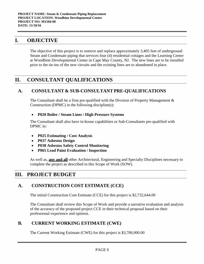
I. OBJECTIVE
The objective of this project is to remove and replace approximately 3,405 feet of underground Steam and Condensate piping that services four (4) residential cottages and the Learning Center at Woodbine Developmental Center in Cape May County, NJ. The new lines are to be installed prior to the tie-ins of the new circuits and the existing lines are to abandoned in place.
II. CONSULTANT QUALIFICATIONS A. CONSULTANT & SUB-CONSULTANT PRE-QUALIFICATIONS
The Consultant shall be a firm pre-qualified with the Division of Property Management & Construction (DPMC) in the following discipline(s):
• P020 Boiler / Steam Lines / High Pressure Systems
The Consultant shall also have in-house capabilities or Sub-Consultants pre-qualified with DPMC in:
• P025 Estimating / Cost Analysis • P037 Asbestos Design • P038 Asbestos Safety Control Monitoring • P065 Lead Paint Evaluation / Inspection
As well as, any and all other Architectural, Engineering and Specialty Disciplines necessary to complete the project as described in this Scope of Work (SOW).
III. PROJECT BUDGET A. CONSTRUCTION COST ESTIMATE (CCE)
The initial Construction Cost Estimate (CCE) for this project is $2,732,644.00 The Consultant shall review this Scope of Work and provide a narrative evaluation and analysis of the accuracy of the proposed project CCE in their technical proposal based on their professional experience and opinion.
B. CURRENT WORKING ESTIMATE (CWE)
The Current Working Estimate (CWE) for this project is $3,700,000.00

PROJECT NAME: Steam & Condensate Piping Replacement PROJECT LOCATION: Woodbine Developmental Center PROJECT NO: M1504-00 DATE: 11/18/16
PAGE 7
The CWE includes the construction cost estimate and all consulting, permitting and administrative fees. The CWE is the Client Agency’s financial budget based on this project Scope of Work and shall not be exceeded during the design and construction phases of the project unless DPMC approves the change in Scope of Work through a Contract amendment.
C. CONSULTANT’S FEES
The construction cost estimate for this project shall not be used as a basis for the Consultant’s design and construction administration fees. The Consultant’s fees shall be based on the information contained in this Scope of Work document and the observations made and/or the additional information received during the pre-proposal meeting.
IV. PROJECT SCHEDULE A. SCOPE OF WORK DESIGN & CONSTRUCTION SCHEDULE
The following schedule identifies the estimated design and construction phases for this project and the estimated durations. PROJECT PHASE ESTIMATED DURATION (Calendar Days) 1. Site Access Approvals & Schedule Design Kick-off Meeting 14
2. Schematic Design Phase 25% (Minimum) 28
• Project Team & DPMC Plan/Code Unit Review & Comment 14 3. Design Development Phase 50% (Minimum) 42
• Project Team & DPMC Plan/Code Unit Review & Comment 14 4. Final Design Phase 100% 42
• Project Team & DPMC Plan/Code Unit Review & Approval 14 5. Permit Application Phase 7
• Issue Plan Release 6. Bid Phase 42 7. Award Phase 28

PROJECT NAME: Steam & Condensate Piping Replacement PROJECT LOCATION: Woodbine Developmental Center PROJECT NO: M1504-00 DATE: 11/18/16
PAGE 8
8. Construction Phase 240 B. CONSULTANT’S PROPOSED DESIGN & CONSTRUCTION SCHEDULE
The Consultant shall submit a project design and construction bar chart schedule with their technical proposal that is similar in format and detail to the schedule depicted in Exhibit ‘A’. The bar chart schedule developed by the Consultant shall reflect their recommended project phases, phase activities, activity durations. The Consultant shall estimate the duration of the project Close-Out Phase based on the anticipated time required to complete each deliverable identified in Section XIV of this document entitled “Contract Deliverables - Project Close-Out Phase” and include this information in the bar chart schedule submitted. A written narrative shall also be included with the technical proposal explaining the schedule submitted and the reasons why and how it can be completed in the time frame proposed by the Consultant. This schedule and narrative will be reviewed by the Consultant Selection Committee as part of the evaluation process and will be assigned a score commensurate with clarity and comprehensiveness of the submission.
C. CONSULTANT DESIGN SCHEDULE The Project Manager will issue the Consultant’s approved project schedule at the first design kickoff meeting. This schedule will be binding for the Consultant’s activities and will include the start and completion dates for each design activity. The Consultant and Project Team members shall use this schedule to ensure that all design milestone dates are being met for the project. The Consultant shall update the schedule to reflect performance periodically (minimally at each design phase) for the Project Team review and approval. Any recommendations for deviations from the approved design schedule must be explained in detail as to the causes for the deviation(s) and impact to the schedule.
D. BID DOCUMENT CONSTRUCTION SCHEDULE The Consultant shall include a construction schedule in Division 1 of the specification bid document. This schedule shall contain, at minimum, the major activities and their durations for each trade specified for the project. This schedule shall be in “bar chart” format and will be used by the Contractors as an aid in determining their bid price. It shall reflect special sequencing or

PROJECT NAME: Steam & Condensate Piping Replacement PROJECT LOCATION: Woodbine Developmental Center PROJECT NO: M1504-00 DATE: 11/18/16
PAGE 9
phased construction requirements including, but not limited to: special hours for building access, weather restrictions, imposed constraints caused by Client Agency program schedules, security needs, lead times for materials and equipment, anticipated delivery dates for critical items, utility interruption and shut-down constraints, and concurrent construction activities of other projects at the site and any other item identified by the Consultant during the design phases of the project.
E. CONTRACTOR CONSTRUCTION PROGRESS SCHEDULE The Contractor shall be responsible for preparing a coordinated combined progress schedule with the Sub-Contractors after the award of the contract. This schedule shall meet all of the requirements identified in the Consultant’s construction schedule. The construction schedule shall be completed in accordance with the latest edition of the Instructions to Bidders and General Conditions and Bulletins that may be issued on the project.
The Consultant must review and analyze this progress schedule and recommend approval/disapproval to the Project Team until a satisfactory version is approved by the Project Team. The Project Team must approve the baseline schedule prior to the start of construction and prior to the Contractor submitting invoices for payment. The Consultant shall note in Division 1 of the specification that the State will not accept the progress schedule until it meets the project contract requirements and any delays to the start of the construction work will be against the Contractor until the date of acceptance by the State. The construction progress schedule shall be reviewed, approved, and updated by the Contractor, Consultant, and Project Team members at each regularly scheduled construction job meeting and the Consultant shall note the date and trade(s) responsible for project delays (as applicable).
V. PROJECT SITE LOCATION & TEAM MEMBERS A. PROJECT SITE ADDRESS
The location of the project site is: Woodbine Developmental Center 1175 DeHirsch Avenue Woodbine, Cape May County, NJ 08270 See Exhibit ‘B’ for the project site plan.

PROJECT NAME: Steam & Condensate Piping Replacement PROJECT LOCATION: Woodbine Developmental Center PROJECT NO: M1504-00 DATE: 11/18/16
PAGE 10
B. PROJECT TEAM MEMBER DIRECTORY
The following are the names, addresses, and phone numbers of the Project Team members. 1. DPMC Representative: Name: Richard Herrero Address: Division Property Management & Construction 20 West State Street, 3rd Floor Trenton, NJ 08608-1206 Phone No: (609) 292-6558 E-Mail No: [email protected] 2.Client Agency Representative: Name: Katherine Fling, Director Address: Department of Human Services 222 South Warren Street PO Box 700 Trenton, NJ 08625 Phone No: (609) 292-0397 E-Mail No: [email protected]
VI. PROJECT DEFINITION A. BACKGROUND
Woodbine Developmental Center was founded in 1921, is located on 250 acres of land in Cape May County. The Woodbine Developmental Center provides residential treatment and rehabilitation services to approximately 600 developmentally disabled men who reside in 18 residential buildings. In addition to the residential cottages and the food services building, the Center contains forty additional buildings that include a medical building, administrative offices, school, recreational facilities, a powerhouse, maintenance facilities and various support facilities. The facility was constructed in 1930 and continues to utilize some of the original buildings. Additional buildings have been constructed and numerous renovations have occurred over the years to maintain compliance with codes and licensing requirements.

PROJECT NAME: Steam & Condensate Piping Replacement PROJECT LOCATION: Woodbine Developmental Center PROJECT NO: M1504-00 DATE: 11/18/16
PAGE 11
The Woodbine Developmental Center needs to replace existing steam and condensate piping that provides heat and air conditioning to four (4) residential cottages and the Learning Center under this project, see Exhibit ‘D’, Proposed Steam Loop.
B. FUNCTIONAL DESCRIPTION OF THE BUILDING
Building Description: 1. Cottages 15, 16, 17 & 18 / Long Term Care Unit:
Cottages 15, 16, 17 and 18 are located adjacent to the Infirmary building. The cottages are one (1) story buildings, approximately 25,000 square feet, constructed in 1981. This buildings house approximately 50 residents that are classified as “medically sensitive” and must have comfortable, stable conditions due to various illnesses and required medications. 2. Learning Center The Learning Center is a 1 1/2 story building with a brick exterior. It functions as the facility’s Learning Center and houses a gymnasium for recreation. There is a Mechanical Room where the final mechanical connections of the new steam and condensate lines are to be tied into the existing header.
C. DESCRIPTION OF THE STEAM AND CONDENSATE LINE SYSTEM
Steam is generated and distributed at 105 psig to most of the WDC campus buildings through a
system of underground piping in buried conduit or tunnels. See Exhibit ‘D’ entitled Proposed Steam Loop for the steam line schematic drawing. Pressure reducing stations are located in the buildings to reduce the steam pressure to approximately 15 psig. The condensate is returned to the boiler house by a number of pumps. The condensate piping is run in the same conduit or tunnel as the steam line.
The majority of the steam and condensate piping that run within the tunnel and underground inner
loop is original dating to the 1930’s, the underground steam and condensate lines that makeup the outer loop were run in the 1950’s. All buried piping are welded sections, not flanged.
The steam and condensate loop was previously replaced in the front of the WDC campus, see
Exhibit ‘D’. The work was completed under DHS Project M1361-00 dated 2/27/09. The drawings

PROJECT NAME: Steam & Condensate Piping Replacement PROJECT LOCATION: Woodbine Developmental Center PROJECT NO: M1504-00 DATE: 11/18/16
PAGE 12
of the DHS Project M1361-00 will be available for viewing at the pre-bid meeting. A copy of the M1361-00 drawings will be awarded to the successful Consulting Firm.
VII. CONSULTANT DESIGN RESPONSIBILITIES A. GENERAL DESIGN OVERVIEW
1. Design Detail: Section VII of this Scope of Work is intended as a guide for the Consultant to understand the overall basic design requirements of the project and is not intended to identify each specific design component related to code and construction items. The Consultant shall provide those details during the design phase of the project ensuring that they are in compliance with all applicable codes, regulating authorities, and the guidelines established in the DPMC Procedures for Architects and Engineers Manual. The Consultant shall understand that construction documents submitted to DPMC shall go beyond the basic requirements set forth by the current copy of the Uniform Construction Code N.J.A.C. 5:23-2.15(f). Drawings and specifications shall provide detail beyond that required to merely show the nature and character of the work to be performed. The construction documents shall provide sufficient information and detail to illustrate, describe and clearly delineate the design intent of the Consultant and enable all Contractors to uniformly bid the project. The Consultant shall ensure that all of the design items described in this scope of work are addressed and included in the project drawings and specification sections where appropriate. It shall be the Consultant’s responsibility to provide all of the design elements for this project. Under no circumstance may they delegate the responsibility of the design; or portions thereof, to the Contractor unless specifically allowed in this Scope of Work. 2. Specification Format: The Consultant shall prepare the construction specifications in the Construction Specifications Institute (CSI) format entitled MasterFormat©, latest edition. The project construction specifications shall include only those CSI MasterFormat© specification sections and divisions applicable to this specific project.

PROJECT NAME: Steam & Condensate Piping Replacement PROJECT LOCATION: Woodbine Developmental Center PROJECT NO: M1504-00 DATE: 11/18/16
PAGE 13
3. Submittal Schedule: The Consultant shall include a submittal schedule in Division 1 of the specifications. The schedule (list of required submittals) shall identify the general conditions and/or specification section (number and name) and the type of submittal required (material data, product data, test results, calculations, etc.). The submittal schedule is a compilation of the submittals required on the project and is provided as an aid to the contractor. 4. Construction Cost Estimates: The Consultant shall include with each design submittal phase identified in Paragraph IV.A, including the Permit Application Phase and Bid Phase, a detailed construction cost estimate itemized and summarized by the divisions and sections of the Construction Specification Institute (CSI) MasterFormat© 2014 applicable to the project. The detailed breakdown of each work item shall include labor, equipment, material and total costs. The construction estimate shall include all alternate bid items and all unit price items itemized and summarized by the divisions and sections of the specifications. All cost estimates shall be adjusted for regional location, site factors, construction phasing, premium time, building use group, location of work within the building, temporary swing space, security issues, and inflation factors based on the year in which the work is to be performed. The cost estimate shall include descriptions of all allowances and contingencies noted in the estimate. All cost estimates must be submitted on a DPMC-38 Project Cost Analysis form at each design phase of the project supported by the detailed construction cost estimate. The Project Manager will provide cost figures for those items which may be in addition to the CCE such as art inclusion, CM services, etc. and must be included as part of the CWE. This cost analysis must be submitted for all projects regardless of the Construction Cost Estimate amount.
B. BUILDING & SITE INFORMATION
The following information shall be included in the project design documents.

PROJECT NAME: Steam & Condensate Piping Replacement PROJECT LOCATION: Woodbine Developmental Center PROJECT NO: M1504-00 DATE: 11/18/16
PAGE 14
1. Building Classification: Provide the building Use Group Classification and Construction Type on the appropriate design drawing. 2. Building Block & Lot Number: Provide the site Block and Lot Number on the appropriate design drawing. 3. Building Site Plan: Only when the project scope involves site work, or when the design triggers code issues that require site information to show code compliance, shall a site plan be provided that is drawn in accordance with an accurate boundary line survey. The site plan shall include, but not be limited to, the following as may be applicable: • The size and location of new and existing buildings and additions as well as other structures. • The distance between buildings and structures and to lot lines. • Established and new site grades and contours as well as building finished floor elevations. • New and existing site utilities, site vehicular and pedestrian roads, walkways and parking
areas. 4. Site Location Map: Provide a site location map on the drawing cover sheet that identifies the vehicular travel routes from major roadways to the project construction site and the approved access roads to the Contractor’s worksite staging area.
C. DESIGN MEETINGS & PRESENTATIONS 1. Design Meetings: Conduct the appropriate number of review meetings with the Project Team members during each design phase of the project so they may determine if the project meets their requirements, question any aspect of the contract deliverables, and make changes where appropriate. The Consultant shall describe the philosophy and process used in the development of the design criteria and the various alternatives considered to meet the project objectives. Selected studies, sketches, cost estimates, schedules, and other relevant information shall be presented to support

PROJECT NAME: Steam & Condensate Piping Replacement PROJECT LOCATION: Woodbine Developmental Center PROJECT NO: M1504-00 DATE: 11/18/16
PAGE 15
the design solutions proposed. Special considerations shall also be addressed such as: Contractor site access limitations, utility shutdowns and switchover coordination, phased construction and schedule requirements, security restrictions, available swing space, material and equipment delivery dates, etc. It shall also be the responsibility of the Consultant to arrange and require all critical Sub-Consultants to be in attendance at the design review meetings. Record the minutes of each design meeting and distribute within seven (7) calendar days to all attendees and those persons specified to be on the distribution list by the Project Manager.
2. Design Presentations:
The Consultant shall make oral presentations of the design documents to the project team members as described below.
a.) Schematic Phase: One meeting 30 days after the completion of Contract Deliverable Items. Total (1) meeting. b.) Design Developmental Phase: One meeting at 50% and one meeting at 100% document completion. Total (2) meetings. c.) Final Design Phase: One meeting at 50% and one meeting at 100% document
completion. Total two (2) meetings. D. STEAMLINE DISTRIBUTION SYSTEM SURVEYS
Provide a site location map on the drawing cover sheet that identifies the vehicular travel routes from major roadways to the project construction site and the approved access roads to the Contractor’s worksite staging area.
1. Site Topographic Survey: The Consultant shall review the topographic information and survey drawings and all other documentation provided by the Client Agency and DPMC at the pre-proposal meeting. Determine their completeness and the need for additional topographic survey information to meet the requirements of this project. The Consultant shall estimate the additional time required to improve the documents and include that amount in the base bid of their fee proposal. 2. Campus Building Survey: Survey all of the Woodbine Developmental Center campus buildings to determine if they presently use steam from the existing steam distribution system and if they will require steam from the new steam distribution system in the future.

PROJECT NAME: Steam & Condensate Piping Replacement PROJECT LOCATION: Woodbine Developmental Center PROJECT NO: M1504-00 DATE: 11/18/16
PAGE 16
Show all of the Woodbine Developmental Center campus buildings on the Woodbine Developmental Center campus site plan and indicate which buildings will require new steam and condensate lines and those that will not require them. Determine the hours of operation, occupancy population, Use Group and Construction Type, and the Block and Lot Number for all of the buildings that will be impacted by the installation of the new steam and condensate lines. Determine the age of the building, the square footage, roof and window system ‘R’ values, and other pertinent information related to energy conservation. Identify how the steam is distributed into the buildings, the location, size, and ratings of all shut-off valves, pressure reducing valves, steam traps, and other related steam component information that will impact the design of this project. Determine if there will be asbestos issues at the point of interface between the existing building piping and the proposed new steam line connections, at the underground distribution piping connections. See Section 7.07 for additional hazardous materials information regarding this project. 3. Underground Utility Survey: The design documents shall identify the existing underground utility line locations, sizes, and elevations of critical crossing points that will be impacted by this project. Underground utilities shall include items such as: fire and domestic water, steam, gas, storm, sewer, fiber optic, cable, and telephone lines, manholes, basin and inlet connections, utility chambers and tunnels, etc. This information shall be used to document their locations on the design drawings and prevent utility line interference, excavation accidents, utility disruption or shutdown during the installation and tie-in of the new lines to the existing utility infrastructure. All “on site” underground utility survey information and previous “on site” underground utility survey reports supplied by the Client Agency or DPMC shall be provided as part of this project and must be field verified and confirmed with line detection methods by the Consultant. The Consultant shall anticipate the costs necessary to update these documents to obtain the appropriate underground utility information and include that amount in the base bid of their fee proposal. 4. Heating Boiler and Piping Survey: Determine the location of the steam and condensate line connections in the boiler room to the new steam and condensate line distribution system. Identify all pipe connection methods and insulation details on the design drawings. Identify any Transite pipe and/or asbestos issues with the existing pipe and provide methods to remediate.

PROJECT NAME: Steam & Condensate Piping Replacement PROJECT LOCATION: Woodbine Developmental Center PROJECT NO: M1504-00 DATE: 11/18/16
PAGE 17
5. Mechanical Equipment Survey: Survey the campus buildings to determine the types of mechanical equipment and systems that utilize steam to heat and cool the buildings. Also identify any equipment utilizing steam for cafeteria food preparation, laundry processes, and production of domestic hot water. Identify the equipment manufacturer’s names, age, capacity, and their condition including all related components. Identify the location of the new steam and condensate line connections to the existing mechanical equipment and identify the connection details including related valves, hangers and pipe supports on the design drawings.
E. STEAM & CONDENSATE LINE DESIGN CRITERIA The Consultant shall ensure that all of the design requirements identified in this section of the scope of work are addressed and included in the project drawings and specification sections where appropriate. The design requirements for this project shall include, but not be limited to the following items: 1. Heating & Cooling Load Calculations: Provide detailed signed and sealed heating and cooling load calculations that indicate the required design loads for the various occupied campus buildings that use steam for their heating, cooling, food preparation, and hot water systems, etc. From this data, confirm that the proposed new steam distribution system and related components are sized for the equipment and systems they serve. 2. Piping: Provide signed and sealed calculations confirming that the size and/or length of the steam and condensate line distribution piping, fittings, and related components are adequate and will not cause excessive pressure or velocity drops in the system. All piping systems and related components shall comply with the current seismic design criteria. The existing steam and condensate lines shall remain operational while the new lines are being installed. Once the new piping systems have been tested and approved, the existing underground burial piping shall be abandoned in place. The Consultant shall provide a Construction Monitor during the piping installation phase of this project, for proper installation.

PROJECT NAME: Steam & Condensate Piping Replacement PROJECT LOCATION: Woodbine Developmental Center PROJECT NO: M1504-00 DATE: 11/18/16
PAGE 18
The Woodbine Developmental Center facility’s domestic hot water and heating systems rely on the steam lines. Switchover to the new piping system shall be coordinated with the Client Agency and disruption to the services shall be minimized. All new underground steam and condensate lines shall be installed a minimum of 10 feet from plastic piping, chilled water systems, fiber optic and telephone lines. They shall have the proper slope in the direction of flow to allow for gravity drainage to the system vaults, low points and other natural drainage points in the system. Profiles shall be drawn to scale indicating the required depth below grade surface and the top and bottom envelope or cross section dimensions of each steam and condensate line that are direct burial. The profiles shall indicate the length, slope and invert elevations of the proposed line and related components. If a valve, flexible coupling, thrust block, tie-rod, etc. is required, they shall be indicated on the profile. Drawing details shall indicate all methods of piping connections and tie-in requirements.
Provide a note on the drawing that all areas of utility line intersections must be hand excavated by the Contractor during construction. Identify the location of any site clearing requirements on the design drawings Identify the location and depth of any underground rock formations in the excavation areas of the construction site. Underground piping systems that run underneath Woodbine Developmental Center campus roadways shall be designed considering the vehicle weight loads and standard DOT design restrictions such as minimum depth requirements of piping conduit below roadway macadam, size of conduit for piping, proper soils fill, and soils compaction requirements. All information shall be included in the design documents. Consideration shall be given to the Woodbine Developmental Center campus site traffic flow and provisions shall be made for alternate routes during construction, in the design documents that have been approved by the Client Agency, Fire Department, and Security personnel. All campus roads that are closed during construction shall be re-opened at the end of every day. Existing penetrations through building walls, manholes, trenches, etc. shall be utilized wherever possible. Interface of the existing pipe insulation system to the new pipe insulation system shall be addressed in the design documents. The configuration of all new lines, valves, and piping components within the buildings shall consider space limitations, required access to piping components for maintenance and repairs, and tie-in methods to the existing building piping distribution system.

PROJECT NAME: Steam & Condensate Piping Replacement PROJECT LOCATION: Woodbine Developmental Center PROJECT NO: M1504-00 DATE: 11/18/16
PAGE 19
A table shall be prepared on the drawing(s) that will summarize the steam and condensate line distribution system pipe diameters and lengths including the lateral lines to the buildings and equipment. All sizes and quantities of the piping components such as meters, valves, backflow preventers, traps, expansion joints, hangers, gages, thermometers, etc. shall also be included in the table. 3. Pressure Reducing Station: Replace the existing pressure reducing stations in the buildings that are to be provided with new steam and condensate lines and make provisions to provide new stations if none exist. 4. Cathodic Protection: All system piping shall have cathodic protection. Proper anode spacing over the length of the steam and condensate lines shall be considered. Test stations located near the manholes shall be provided for the system and shall include a utilities type cover and proper “test station” identification tag. 5. Pipe and Valve Insulation: All steam and condensate lines, valves, fittings, and related components shall be properly insulated and shall have an appropriate insulation ‘R’ value to prevent thermal losses. The insulation may not be water soluble and shall have waterproof membrane protection that will not react and fail from exposure to water, condensation, and humidity. The pipe insulation system recommended shall have a proven history of successful operation and shall be demonstrated by the Consultant with documentation that must be approved by the 6. Condensate Pumps: Provide new duplex condensate pumps and all related equipment. The units shall be factory assembled, packaged, pre-piped, and factory tested. 7. Valves: Provide valves at all appropriate points of the steam and condensation system including the manholes, tunnels, boiler room, and buildings so that sections of the system may be isolated for scheduled seasonal shutdowns, loop drainage, or system repairs. Investigate and provide new isolation valves outside buildings at the connection to utility main and inside the buildings before any branch connections or devices. Valve boxes shall be

PROJECT NAME: Steam & Condensate Piping Replacement PROJECT LOCATION: Woodbine Developmental Center PROJECT NO: M1504-00 DATE: 11/18/16
PAGE 20
provided in the ground for access and maintenance of the valves. Provide curb stops to enable shut-off of isolation valves. All valves that are tied into the steam and condensate line headers shall be equipped with by-pass valves. Provide check valves in the distribution system where required. Provide isolation valves at all distribution system strainers, traps, condensate pumps, and other related components so that they may be repaired or replaced without shutting down the system. Provide pressure reducing and safety relief valves in the steam and condensate lines where appropriate. Inspect all existing valves for proper operation. Valves found inoperable should be repaired or replaced upon the A/E’s recommendation. 8. Steam Traps: Install steam traps in accessible locations with pressure and temperature gauges and include shut off valves, unions, cross tees with test valves, and check valves that will permit removing the trap set as a unit for repair or replacement. 9. Pressure Gauges & Thermometers: Provide pressure gauges and thermometers in appropriate locations of the new steam and condensate line distribution system. Provide pressure snubbers and shut off valves on all gauges.
10. Hangers, Supports, Anchors, Thrust Blocks, and Expansion Loops: All expansion loops shall be horizontal and located underground. Provide details on the drawings for all required hangers, supports, anchors, thrust blocks, supports, and guides as required by appropriate design and codes. Support of steam and condensate piping must account for proper direction of expansion and contraction, vibration and the dead load of the piping and its contents. Location of supports, anchors, and guides for underground piping shall meet insulation manufacturer’s requirements. 11. Trenches:

PROJECT NAME: Steam & Condensate Piping Replacement PROJECT LOCATION: Woodbine Developmental Center PROJECT NO: M1504-00 DATE: 11/18/16
PAGE 21
Pipe trench dimensions, shoring details, barrier and fencing locations, safety site lighting, warning signs, soils stockpile locations, soil erosion precautions, dewatering requirements, OSHA requirements, and other relevant information shall be included in the design documents. All new steam and condensate lines shall be supported on undisturbed material or properly compacted backfill. Backfilling of trenches shall progress as rapidly as construction, testing, inspections, and acceptance of work is completed. Design documents shall require compaction tests for all backfilled trenches. All excess excavated soil material shall be removed from the site and disposed by the Contractor. Describe the site restoration work required after the installation of the steam and condensate lines including grading and seeding of the lawn areas, and the replacement of disturbed sidewalk and driveway areas. 12. Manholes: It is the intent of this project to use new vaults and not to reuse the existing manholes. The vault shall be constructed 4-6” above grade. Provide 3’ x 6’ access doors for each steam vault. Provide new manholes where required and appropriate locations. Manholes to be vented as per existing vents. 13. Observation Ports The Consultant shall consider the addition of observation ports if they are deemed a practical means by which to identify problems with the pipe and that the cost of their installation is insignificant as compared to their benefit. 14. Piping System Tests: Develop detailed piping system test requirements and ensure that they are incorporated into the specifications so that the Contractors may budget the proper amount of time for these tests in their bid proposals. The design specification testing information shall include, but not be limited to the following information: the purpose of the test, required personnel, tools, and instruments needed to perform the tests, design information pertinent to the equipment or system being tested, equipment description, detailed test sequence, test pressures and durations, special instructions or warnings, expected results, and sample strategies. All appropriate approval authorities and/or Agencies shall observe the tests and the data shall be reviewed and approved by the Consultant. The Contractor shall provide a certificate testifying that the system was satisfactorily tested as specified and passed.

PROJECT NAME: Steam & Condensate Piping Replacement PROJECT LOCATION: Woodbine Developmental Center PROJECT NO: M1504-00 DATE: 11/18/16
PAGE 22
The certification shall also provide the following information: • Identification of the system tested and references to the specific equipment connected to
the system. • Date tested. • Test pressure and duration of test. • All recorded test data. • Media used for the testing. • List of necessary repairs made before system passed the test. • Signature of the Contractor. • Signature of the inspector. • Other data as required by the Consultant. Three (3) copies of the test results shall be forwarded to the DPMC Project Manager for distribution. Clean and flush all of the piping systems and components. Replace all start-up strainers and leave the system in proper working order after the tests. 15. As-Built Documentation: The Consultant shall ensure that the Contractor measures and records the locations, depths below surface, and the top and bottom envelop or cross section of all the new steam and condensate lines, anchors, thrust blocks, expansion loops, manholes, valve boxes, vaults, etc. that are installed during the construction phase of the project and that the data is transferred to the as-built set of drawings for future reference. The project will not be closed-out without this information.
F. ASBESTOS
The design documents shall address the potential removal requirements for asbestos for this project including, but not be limited to the following items: 1. ASCM Firm: The Consultant shall be responsible for determining which of the piping systems will be impacted by any proposed construction work for this project. The Consultant shall then employ the services of a firm certified by DCA and pre-qualified with DPMC in the Asbestos Safety Control Monitoring Specialty Discipline (ASCM). The Consultant may contact the NJ State website: www.state.nj.us/treasury/dpmc/construction/consult_search.html for a list of pre-qualified firms.

PROJECT NAME: Steam & Condensate Piping Replacement PROJECT LOCATION: Woodbine Developmental Center PROJECT NO: M1504-00 DATE: 11/18/16
PAGE 23
2. Design Documents: The ASCM firm shall collect samples of the materials in all areas identified to be impacted by the construction work using the “AHERA PROTOCOL” and analyze them for the presence of asbestos. If present, the ASCM firm, under the direction of the Consultant, shall prepare asbestos abatement design documents which shall be incorporated in the project design documents prepared by the Consultant and will be bid as one package. The ASCM firm shall also be responsible for the submission of the design documents to the DCA Asbestos Control Group for review, approval and issuance of a permit. DCA will issue the Certificate of Occupancy when the project is complete. 3. Asbestos Sub-Contractor: It shall be the responsibility of the single prime Contractor to employ the services of a qualified asbestos Sub-Contractor. The Consultant shall ensure that the scheduled asbestos removal has minimal impact on all construction activities and project schedules. The ASCM firm shall provide monitoring and construction administration services during the asbestos abatement activities including submissions of all Hazardous Waste Manifests to the DPMC Project Manager at the completion of the project. 4. Finishes: The restoration of all finishes affected by this work shall be part of this project contract. All restorations to be equivalent to existing or better. 5. Air Samples: The design documents shall also state that the Contractor shall be responsible for any and all air samples as may be required by OSHA, Federal Lead in Construction Standards, and other applicable standards for this work. 6. Consolidation of Tasks: One firm may perform all of the tasks described above if they are pre-qualified with DPMC and have the license, certification, or approval required by the appropriate regulating authority to perform those tasks. 7. Survey Report: The Consultant shall submit three (3) copies of the final “Hazardous Materials Survey Report” to the DPMC Project Manager. The report shall identify all of the hazardous materials found at the project site and include copies of the test lab results for each material and a schematic

PROJECT NAME: Steam & Condensate Piping Replacement PROJECT LOCATION: Woodbine Developmental Center PROJECT NO: M1504-00 DATE: 11/18/16
PAGE 24
plan showing their location. All illustrative material, pictures, or drawings developed during the investigation shall be included for reference. 8. Hazardous Materials Allowance Costs: The Sub-Consulting firm(s) selected by the Consultant to conduct the hazardous materials tests, prepare the potential design documents, and provide construction administration services shall estimate all of the costs associated with their work and submit that amount to the Consultant prior to the proposed due date. The Consultant shall enter the amount submitted by the Sub-Consulting firm(s) on the fee proposal line item entitled “Hazardous Materials Allowance” and attach a detailed cost breakdown sheet for use by the Project Team members during the proposal review and potential fee negotiations. The cost breakdown sheet shall include, but not be limited to the following information: a. Hazardous Material Inspection & Assessment Phase • Total Number of Bulk Samples to be Collected • Bulk Sample Collection Unit Cost • Bulk Sample Lab Analysis Unit Cost • Instrumentation/Equipment Costs • Hazardous Materials Survey Report Cost b. Abatement Design & Construction Administration Phases • Meeting Costs • Drawing Costs • Specification Costs • Construction Administration Costs • Any funds remaining in the Allowance at the end of the project shall be returned to the
State.
G. PROJECT COMMENCEMENT
A pre-design meeting shall be scheduled with the Consultant and the Project Team members at the commencement of the project to obtain and/or coordinate the following information: 1. Project Directory:

PROJECT NAME: Steam & Condensate Piping Replacement PROJECT LOCATION: Woodbine Developmental Center PROJECT NO: M1504-00 DATE: 11/18/16
PAGE 25
Develop a project directory that identifies the name and phone number of key designated representatives who may be contacted during the design and construction phases of this project. 2. Site Access: Develop procedures to access the project site and provide the names and phone numbers of approved escorts when needed. Obtain copies of special security and policy procedures that must be followed during all work conducted at the facility and include this information in Division 1 of the specification. 3. Project Coordination: Review and become familiar with any current and/or future projects at the site that may impact the design, construction, and scheduling requirements of this project. Incorporate all appropriate information and coordination requirements in Division 1 of the specification. 4. Existing Documentation: Copies of the following documents will be provided for viewing at the pre-proposal meeting to assist in the bidding process. Copies of the referenced documents will be awarded to the successful Consulting Firm. DPMC Project: M1361-00, Steam and Condensate Line Replacement, Dated 3/29/12, Miller- Remick Corporation
Review these documents and any additional information that may be provided at a later date such as reports, studies, surveys, equipment manuals, as-built drawings, etc. The State does not attest to the accuracy of the information provided and accepts no responsibility for the consequences of errors by the use of any information and material contained in the documentation provided. It shall be the responsibility of the Consultant to verify the contents and assume full responsibility for any determination or conclusion drawn from the material used. If the information provided is insufficient, the Consultant shall take the appropriate actions necessary to obtain the additional information required. All original documentation shall be returned to the provider at the completion of the project. 5. Scope of Work: Review the design and construction administration responsibilities and the submission requirements identified in this Scope of Work with the Project Team members. Items such as: contract deliverables, special sequencing or phased construction requirements, special hours for construction based on Client Agency programs or building occupancy, security needs, delivery

PROJECT NAME: Steam & Condensate Piping Replacement PROJECT LOCATION: Woodbine Developmental Center PROJECT NO: M1504-00 DATE: 11/18/16
PAGE 26
dates of critical and long lead items, utility interruptions or shut down constraints for tie-ins, weather restrictions, and coordination with other project construction activities at the site shall be addressed. This information and all general administrative information; including a narrative summary of the work for this project, shall be included in Division 1 of the specification. The Consultant shall assure that there are no conflicts between the information contained in Division 1 of the specification and the DPMC General Conditions.
6. Project Schedule: Review and update the project design and construction schedule with the Project Team members.
H. CONSTRUCTION BID DOCUMENT SUBMITTAL
In addition to submitting construction bid documents as defined in Section XIV Contract Deliverables, Consultant shall submit both specifications and drawings on compact disk (CD) in Adobe Portable Document Format (.pdf).
VIII. CONSULTANT CONSTRUCTION RESPONSIBILITIES A. GENERAL CONSTRUCTION ADMINISTRATION OVERVIEW
This section of the Scope of Work is intended as a guide for the Consultant to understand their overall basic construction administration responsibilities for the project and does not attempt to identify each specific activity or deliverable required during this phase. The Consultant shall obtain that information from the current publication of the DPMC Procedures for Architects and Engineers Manual and any additional information provided during the Consultant Selection Process.
B. PRE-BID MEETING The Consultant shall attend, chair, record and distribute minutes of the Contractor pre-bid meetings. When bidders ask questions that may affect the bid price of the project, the Consultant shall develop a Bulletin(s) to clarify the bid documents in the format described in the Procedures for Architects and Engineers Manual, Section 9.2 entitled “Bulletins.” These Bulletins must be sent to DPMC at least seven (7) calendar days prior to the bid opening date. DPMC will then distribute the document to all bidders.
C. BID OPENING The Consultant must attend the bid opening held at the designated location.

PROJECT NAME: Steam & Condensate Piping Replacement PROJECT LOCATION: Woodbine Developmental Center PROJECT NO: M1504-00 DATE: 11/18/16
PAGE 27
In the event that the construction bids received exceed the Consultant’s approved final cost estimate by 5% or more, the Consultant shall redesign and/or set up sufficient approved alternate designs, plans and specifications for the project work, to secure a bid that will come within the allocation specified by the State without impacting the programmatic requirements of the project. Such redesign work and changes to plans, including reproduction costs for submission in order to obtain final approval and permits, shall be undertaken by the Consultant at no additional cost to the State.
D. POST BID REVIEW MEETING, RECOMMENDATION FOR AWARD The Consultant; in conjunction with the Project Manager, shall review the bid proposals submitted by the various Contractors to determine the low responsible bid for the project. The Consultant; in conjunction with the Project Manager and Project Team members, shall develop a post bid questionnaire based on the requirements below and schedule a post bid review meeting with the Contractor’s representative to review the construction costs and schedule, staffing, and other pertinent information to ensure they understand the Scope of the Work and that their bid proposal is complete and inclusive of all requirements necessary to deliver the project in strict accordance with the plans and specifications. 1. Post Bid Review: Review the project bid proposals including the alternates, unit prices, and allowances within seven (7) calendar days from the bid due date. Provide a bid tabulation matrix comparing all bids submitted and make a statement about the high, low, and average bids received. Include a comparison of the submitted bids to the approved current construction cost estimate. When applicable, provide an analysis with supporting data, detailing why the bids did not meet the construction cost estimate. 2. Review Meeting: Arrange a meeting with the apparent low bid Contractor to discuss their bid proposal and other issues regarding the award of the contract. Remind the Contractor that this is a Lump Sum bid. Request the Contractor to confirm that their bid proposal does not contain errors. Review and confirm Alternate pricing and Unit pricing and document acceptance or rejection as appropriate. Comment on all omissions, qualifications and unsolicited statements appearing in the proposals. Review any special circumstances of the project. Ensure the Contractor’s signature appears on all post bid review documents. 3. Substitutions:

PROJECT NAME: Steam & Condensate Piping Replacement PROJECT LOCATION: Woodbine Developmental Center PROJECT NO: M1504-00 DATE: 11/18/16
PAGE 28
Inquire about any potential substitutions being contemplated by the Contractor and advise them of the State’s guidelines for the approval of substitutions and the documentation required. Review the deadline and advise the Contractor that partial submissions are not acceptable. Submission after the deadline may be rejected by the State. Equal substitutions that are proposed by the Contractor that are of lesser value must have a credit change order attached with the submittal (See Article 4.7.5 “Substitutions” of the General Conditions). The State has the right to reject the submission if there is no agreement on the proposed credit. Contractor will be responsible to submit a specified item. 4. Schedule: Confirm that the Contractor is aware of the number of calendar days listed in the contract documents for the project duration and that the Contractor’s bid includes compliance with the schedule duration and completion dates. Particular attention shall be given to special working conditions, long lead items and projected delivery dates, etc. Review project milestones (if applicable). This could give an indication of Contractor performance, but not allow a rejection of the bid. Review the submittal timeframes per the Contract documents. Ask the Contractor to identify what products will take over twenty-eight (28) calendar days to deliver from the point of submittal approval. If a CPM Schedule is required, review the provisions and have Contractor acknowledge the responsibility. Ask for the name of the CPM Scheduler and the “ballpark” costs. 5. Performance: Investigate the past performance of Contractor by contacting Architects and owners (generally three of each) that were listed in their DPMC pre-qualification package and other references that may have been provided. Inquire how the Contractor performed with workmanship, schedule, project management, change orders, cooperation, paper work, etc. 6. Letter of Recommendation: The Consultant shall prepare a Letter of Recommendation for contract award to the Contractor submitting the lowest responsible bid within three (3) calendar days from the post bid review meeting. The document shall contain the project title, DPMC project number, bid due date and expiration date of the proposal. It shall include a detailed narrative describing each post bid meeting agenda item identified above and a recommendation to award the contract to the apparent low bid Contractor based on the information obtained during that meeting. Describe any acceptance or rejection of Alternate pricing and Unit pricing.

PROJECT NAME: Steam & Condensate Piping Replacement PROJECT LOCATION: Woodbine Developmental Center PROJECT NO: M1504-00 DATE: 11/18/16
PAGE 29
Comment on any discussion with the Contractor that provides a sense of their understanding of the project and any special difficulties that they see, and how they might approach those problems. Attach all minutes of the Post bid meeting and any other relevant correspondence with the Letter of Recommendation and submit them to the Project Manager. 7. Conformed Drawings: The Consultant shall prepare and distribute two (2) sets of drawings stamped “Conformed Drawings” to the Project Manager that reflect all Bulletins and/or required changes, additions, and deletions to the pertinent drawings within fourteen (14) calendar days of the construction contract award date. Any changes made in Bulletins, meeting minutes, post bid review requirements shall also be reflected in the specification.
E. DIRECTOR’S HEARING
The Consultant must attend any Director’s hearing(s) if a Contractor submits a bid protest. The Consultant shall be present to interpret the intent of the design documents and answer any technical questions that may result from the meeting. In cases where the bid protest is upheld, the Consultant shall submit a new “Letter of Recommendation” for contract award. The hours required to attend the potential hearings and to document the findings shall be estimated by the Consultant and the costs will be included in the base bid of their fee proposal.
F. CONSTRUCTION JOB MEETINGS, SCHEDULES, LOGS The Consultant shall conduct all of the construction job meetings, to be held bi-weekly for the duration of construction, in accordance with the procedures identified in the A/E manual and those listed below. 1. Meetings: The Consultant and Sub-Consultant(s) shall attend the pre-construction meeting and all construction job meetings during the construction phase of the project. The Consultant shall chair the meeting, transcribe and distribute the job-meeting minutes for every job meeting to all attendees and to those persons specified to be on the distribution list by the Project Manager. The Agenda for the meeting shall include, but not be limited to the items identified in the Procedures for Architects and Engineers Manual, Section 10.3.1, entitled “Agenda.” Also, the Consultant is responsible for the preparation and distribution of minutes within three (3) calendar days of the meeting. The format to be used for the minutes shall comply with those

PROJECT NAME: Steam & Condensate Piping Replacement PROJECT LOCATION: Woodbine Developmental Center PROJECT NO: M1504-00 DATE: 11/18/16
PAGE 30
identified in the “Procedures for Architects and Engineers Manual,” Section 10.3.4, entitled, “Format of Minutes.” All meeting minutes are to have an “action” column indicating the party that is responsible for the action indicated and a deadline to accomplish the assigned task. These tasks must be reviewed at each job progress meeting until it is completed and the completion date of each task shall be noted in the minutes of the meeting following the task completion.
2. Schedules:
The Consultant; with the input from the Client Agency Representative and Project Manager, shall review and recommend approval of the project construction schedule prepared by the Contractor. The schedule shall identify all necessary start and completion dates of construction, construction activities, submittal process activities, material deliveries and other milestones required to give a complete review of the project.
The Consultant shall record any schedule delays, the party responsible for the delay, the schedule activity affected, and the original and new date for reference.
The Consultant shall ensure that the Contractor provides a two (2) week “look ahead” construction schedule based upon the current monthly updated schedule as approved at the bi-weekly job meetings and that identifies the daily planned activities for that period. This Contractor requirement must also be included in Division 1 of the specification for reference.
3. Submittal Log:
Based on the Submittal Schedule in Division 1 of the specifications, the Consultant shall develop and implement a submittal log that includes all of the required project submittals as identified in the general conditions and technical specifications. The dates of submission shall be determined and approved by all affected parties during the pre-construction meeting.
Examples of the submissions to be reviewed and approved by the Consultant and Sub-Consultant (if required) include: project schedule, schedule of values, shop drawings, equipment and material catalog cuts, spec sheets, product data sheets, MSDS material safety data sheets, specification procedures, color charts, material samples, mock-ups, etc. The submittal review process must be conducted at each job progress meeting and shall include the Consultant, Sub-Consultant, Contractor, Project Manager, and designated representatives of the Client Agency.
The Consultant shall provide an updated submittal log at each job meeting that highlights the status of all required submissions.
G. CONSTRUCTION SITE ADMINISTRATION SERVICES
The Consultant and Sub-Consultant(s) shall provide construction site administration services during the duration of the project. The Consultant and Sub-Consultant(s) do not necessarily have

PROJECT NAME: Steam & Condensate Piping Replacement PROJECT LOCATION: Woodbine Developmental Center PROJECT NO: M1504-00 DATE: 11/18/16
PAGE 31
to be on site concurrently if there are no critical activities taking place that require the Sub-Consultant’s participation. The services required shall include, but not be limited to; field observations sufficient to verify the quality and progress of construction work, conformance and compliance with the contract documents, and to attend/chair meetings as may be required by the Project Manager to resolve special issues. Consultant and Sub-Consultant(s) shall conduct weekly site inspection/field observation visits. Site inspection/field observation visits may be conducted in conjunction with regularly scheduled bi-weekly construction job meetings, depending on the progress of work, for weeks that construction job meetings are scheduled. The Consultant and their Sub-Consultant(s) shall submit a field observation report for each site inspection to the Project Manager within three (3) calendar days of the site visit. Also, they shall conduct inspections during major construction activities including, but not limited to the following examples: concrete pours, steel and truss installations, code inspections, final testing of systems, achievement of each major milestone required on the construction schedule, and requests from the Project Manager. The assignment of a full time on-site Sub-Consultant does not relieve the Consultant of their site visit obligation. The Consultant shall refer to Section XIV. Contract Deliverables of this Scope of Work subsection entitled “Construction Phase” to determine the extent of services and deliverables required during this phase of the project.
H. SUB-CONSULTANT PARTICIPATION It is the responsibility of the Consultant to ensure that they have provided adequate hours and/or time allotted in their technical proposal so that their Sub-Consultants may participate in all appropriate phases and activities of this project or whenever requested by the Project Manager. This includes the pre-proposal site visit and the various design meetings and construction job meetings, site visits, and close-out activities described in this Scope of Work. Field observation reports and/or meeting minutes are required to be submitted to the Project Manager within three (3) calendar days of the site visit or meeting. All costs associated with such services shall be included in the base bid of the Consultant’s fee proposal.
I. DRAWINGS 1. Shop Drawings: Each Contractor shall review the specifications and determine the numbers and nature of each shop drawing submittal. Five (5) sets of the documents shall be submitted with reference made to the appropriate section of the specification. The Consultant shall review the Contractor’s shop drawing submissions for conformity with the construction documents within seven (7) calendar

PROJECT NAME: Steam & Condensate Piping Replacement PROJECT LOCATION: Woodbine Developmental Center PROJECT NO: M1504-00 DATE: 11/18/16
PAGE 32
days of receipt. The Consultant shall return each shop drawing submittal stamped with the appropriate action, i.e. “Approved”, “Approved as Noted”, “Approved as Noted Resubmit for Records”, “Rejected”, etc.
2. As-Built & Record Set Drawings:
The Contractor(s) shall keep the contract drawings up-to-date at all times during construction and upon completion of the project, submit their AS-BUILT drawings to the Consultant with the Contractor(s) certification as to the accuracy of the information prior to final payment. All AS-BUILT drawings submitted shall be entitled AS-BUILT above the title block and dated.
The Consultant shall review the Contractor(s)’ AS-BUILT drawings at each job progress meeting to ensure that they are up-to-date. Any deficiencies shall be noted in the progress meeting minutes.
The Consultant shall acknowledge acceptance of the AS-BUILT drawings by signing a transmittal indicating they have reviewed them and that they reflect the AS-BUILT conditions as they exist.
Upon receipt of the AS-BUILT drawings from the Contractor(s), the Consultant shall obtain the original reproducible drawings from DPMC and transfer the AS-BUILT conditions to the original full sized signed reproducible drawings to reflect RECORD conditions within fourteen (14) calendar days of receipt of the AS-BUILT information.
The Consultant shall note the following statement on the original RECORD-SET drawings. “The AS-BUILT information added to this drawing(s) has been supplied by the Contractor(s). The Architect/Engineer does not assume the responsibility for its accuracy other than conformity with the design concept and general adequacy of the AS-BUILT information to the best of the Architect’s/Engineer’s knowledge.”
Upon completion, The Consultant shall deliver the RECORD-SET original reproducible drawings to DPMC who will acknowledge their receipt in writing. This hard copy set of drawings and two (2) sets of current release AUTO CAD discs shall be submitted to DPMC. The discs shall contain all AS-BUILT drawings in both “.dwg” (native file format for AUTO CAD) and “.pdf” (Adobe portable document format) file formats.
J. CONSTRUCTION DEFICIENCY LIST
The Consultant shall prepare, maintain and continuously distribute an on-going deficiency list to the Contractor, Project Manager, and Client Agency Representative during the construction phase of the project. This list shall be separate correspondence from the field observation reports and shall not be considered as a punch list.

PROJECT NAME: Steam & Condensate Piping Replacement PROJECT LOCATION: Woodbine Developmental Center PROJECT NO: M1504-00 DATE: 11/18/16
PAGE 33
K. INSPECTIONS: SUBSTANTIAL & FINAL COMPLETION The Consultant and their Sub-Consultant(s) accompanied by the Project Manager, Code Inspection Group, Client Agency Representative and Contractor shall conduct site inspections to determine the dates of substantial and final completion. The Project Manager will issue the only recognized official notice of substantial completion. The Consultant shall prepare and distribute the coordinated punch list, written warranties and other related DPMC forms and documents, supplied by the Contractor, to the Project Manager for review and certification of final contract acceptance. If applicable, the punch list shall include a list of attic stock and spare parts.
L. CLOSE-OUT DOCUMENTS The Consultant shall review all project close-out documents as submitted by the Contractors to ensure that they comply with the requirements listed in the “Procedure for Architects and Engineers’ Manual.” The Consultant shall forward the package to the Project Manager within fourteen (14) calendar days from the date the Certificate of Occupancy/Certificate of Approval is issued. The Consultant shall also submit a letter certifying that the project was completed in accordance with the contract documents, etc.
M. CLOSE-OUT ACTIVITY TIME The Consultant shall provide all activities and deliverables associated with the “Close-Out Phase” of this project as part of their Lump Sum base bid. The Consultant and/or Sub-Consultant(s) may not use this time for additional job meetings or extended administrative services during the Construction Phase of the project.
N. TESTING, TRAINING, MANUALS AND ATTIC STOCK The Consultant shall ensure that all equipment testing, training sessions and equipment manuals required for this project comply with the requirements identified below. 1. Testing: All equipment and product testing conducted during the course of construction is the responsibility of the Contractor. However, the Consultant shall ensure the testing procedures comply with manufacturers recommendations. The Consultant shall review the final test reports and provide a written recommendation of the acceptance/rejection of the material, products or equipment tested within seven (7) calendar days of receipt of the report.

PROJECT NAME: Steam & Condensate Piping Replacement PROJECT LOCATION: Woodbine Developmental Center PROJECT NO: M1504-00 DATE: 11/18/16
PAGE 34
2. Training: The Consultant shall include in the specification that the Contractor shall schedule and coordinate all equipment training with the Project Manager and Client Agency representatives. It shall state that the Contractor shall submit the Operation and Maintenance (O&M) manuals, training plan contents, and training durations to the Consultant, Project Manager and Client Agency Representative for review and approval prior to the training session. The Consultant shall ensure that the training session is “videotaped” by the Contractor. A copy of the “videotape” shall be transmitted to the Project Manager who will forward the material to the Client Agency for future reference. All costs associated with the training sessions shall be borne by the Contractor installing the equipment. A signed letter shall be prepared stating when the training was completed and must be accompanied with the training session sign-in sheet as part of the project close-out package. 3. Operation & Maintenance Manuals: The Consultant shall coordinate and review the preparation and issuance of the equipment manuals provided by the Contractor(s) ensuring that they contain the operating procedures, maintenance procedures and frequency, cut sheets, parts lists, warranties, guarantees, and detailed drawings for all equipment installed at the facility. A troubleshooting guide shall be included that lists problems that may arise, possible causes with solutions, and criteria for deciding when equipment shall be repaired and when it must be replaced. Include a list of the manufacturer’s recommended spare parts for all equipment being supplied for this project. A list of names, addresses and telephone numbers of the Contractors involved in the installations and firms capable of performing services for each mechanical item shall be included. The content of the manuals shall be reviewed and approved by the Project Manager and Client Agency Representative. The Consultant shall include in the specification that the Contractor must provide a minimum of ten (10) “throwaway” copies of the manual for use at the training seminar and seven (7) hardbound copies as part of the project close-out package.

PROJECT NAME: Steam & Condensate Piping Replacement PROJECT LOCATION: Woodbine Developmental Center PROJECT NO: M1504-00 DATE: 11/18/16
PAGE 35
4. Attic Stock: The Consultant shall determine and recommend whether “attic stock” should be included for all aspects of the project. If required, the Consultant shall specify attic stock items to be included in the project.
Prior to project close-out, the Consultant must prepare a comprehensive listing of all items for delivery by the Contractor to the Owner and in accordance with the appropriate specification/plan section. Items shall include, but not be limited to: training sessions, O&M manuals, as-built drawings, itemized attic stock requirements, and manufacturer guarantees/warranties.
O. CHANGE ORDERS
The Consultant shall review and process all change orders in accordance with the contract documents and procedures described below. 1. Consultant: The Consultant shall prepare a detailed request for Change Order including a detailed description of the change(s) along with appropriate drawings, specifications, and related documentation and submit the information to the Contractor for the change order request submission. This will require the use of the current DPMC 9b form. 2. Contractor: The Contractor shall submit a DPMC 9b Change Order Request form to the Project Manager within seven (7) calendar days after receiving the Change Order from the Consultant. The document shall identify the changed work in a manner that will allow a clear understanding of the necessity for the change. Copies of the original design drawings, sketches, etc. and specification pages shall be highlighted to clarify and show entitlement to the Change Order. Copies shall be provided of job minutes or correspondence with all relative information highlighted to show the origin of the Change Order. Supplementary drawings from the Consultant shall be included if applicable that indicate the manner to be used to complete the changed work. A detailed breakdown of all costs associated with the change, i.e. material, labor, equipment, overhead, Sub-Contractor work, profit and bond, and certification of increased bond shall be provided. If the Change Order will impact the time of the project, the Contractor shall include a request for an extension of time. This request shall include a copy of the original approved project schedule and a proposed revised schedule that reflects the impact on the project completion date. Documentation to account for the added time requested shall be included to support entitlement

PROJECT NAME: Steam & Condensate Piping Replacement PROJECT LOCATION: Woodbine Developmental Center PROJECT NO: M1504-00 DATE: 11/18/16
PAGE 36
of the request such as additional work, weather, other Contractors, etc. This documentation shall contain dates, weather data and all other relative information.
3. Recommendation for Award:
The Consultant shall evaluate the reason for the change in work and provide a detailed written recommendation for approval or disapproval of the Change Order Request including backup documentation of costs in CSI format and all other considerations to substantiate that decision.
4. Code Review:
The Consultant shall determine if the Change Order request will require Code review and shall submit six (6) sets of signed and sealed modified drawings and specifications to the DPMC Plan & Code Review Unit for approval, if required. The Consultant must also determine and produce a permit amendment request if required.
5. Cost Estimate:
The Consultant shall provide a detailed cost estimate of the proposed Change Order Request, as submitted by the Contractor, in CSI format (2004 Edition) for all appropriate divisions and sub-divisions using a recognized estimating formula. The estimate shall then be compared with that of the Contractor’s estimate. If any line item in the Consultant’s estimate is lower than the corresponding line item in the Contractor’s estimate, the Consultant in conjunction with the Project Manager is to contact the Contractor by telephone and negotiate the cost differences. The Consultant shall document the negotiated agreement on the Change Order Request form. If the Contractor’s total dollar value changes based on the negotiations, the Consultant shall identify the changes on the Change Order Request form accordingly.
When recommending approval or disapproval of the change order, the Consultant shall be required to prepare and process a Change Order package that contains at a minimum the following documents:
• DPMC 9b Change Order Request• DPMC 10 Consultant’s Evaluation of Contractor’s Change Order Request• Consultant’s Independent Detailed Cost Estimate• Notes of Negotiations
6. Time Extension:
When a Change Order Request is submitted with both cost and time factors, the Consultant’s independent cost estimate is to take into consideration time factors associated with the changed work. The Consultant is to compare their time element with that of the Contractor’s time request

PROJECT NAME: Steam & Condensate Piping Replacement PROJECT LOCATION: Woodbine Developmental Center PROJECT NO: M1504-00 DATE: 11/18/16
PAGE 37
and if there is a significant difference, the Consultant in conjunction with the Project Manager is to contact the Contractor by telephone and negotiate the difference.
When a Change Order Request is submitted for time only, the Consultant is to do an independent evaluation of the time extension request using a recognized scheduling formula. Requests for extension of contract time must be done in accordance with the General Conditions Article 10.1 “Changes in the Work”. 7. Submission: The Consultant shall complete all of the DPMC Change Order Request forms provided and submit a completed package to the Project Manager with all appropriate backup documentation within seven (7) calendar days from receipt of the Contractor’s change order request. The Consultant shall resubmit the package at no cost to the State if the change order package contents are deemed insufficient by the Project Manager. 8. Meetings: The Consultant shall attend and actively participate at all administrative hearings or settlement conferences as may be called by Project Manager in connection with such Change Orders and provide minutes of those meetings to the Project Manager for distribution.
9. Consultant Fee: All costs associated with the potential Contractor Change Order Requests shall be anticipated by the Consultant and included in the base bid of their fee proposal. If the Client Agency Representative requests a scope change; and it is approved by the Project Manager, the Consultant may be entitled to be reimbursed through an amendment and in accordance with the requirements stated in paragraph 10.01 of this Scope of Work.
IX. PERMITS & APPROVALS
A. NJ UNIFORM CONSTRUCTION CODE PERMIT The project construction documents must comply with the latest adopted edition of the NJ Uniform Construction Code (NJUCC). The latest NJUCC Adopted Codes and Standards can be found at:

PROJECT NAME: Steam & Condensate Piping Replacement PROJECT LOCATION: Woodbine Developmental Center PROJECT NO: M1504-00 DATE: 11/18/16
PAGE 38
http://www.state.nj.us/dca/divisions/codes/codreg/ The Consultant shall complete the NJUCC permit application and all applicable technical sub-code sections with all technical site data required. The Agent section of the application and certification section of the building sub-code section shall be signed. These documents shall be forwarded to the DPMC Project Manager who will send them to the Department of Community Affairs (DCA) and all permit application costs will be paid by DPMC. The Consultant may obtain copies of all NJUCC permit applications at the following website: http://www.state.nj.us/dca/divisions/codes/forms/ All other required project permits shall be obtained and paid for by the Consultant in accordance with the procedures described in Paragraph IX.B. 1. Prior Approval Certification Letters: The issuance of a construction permit for this project may be contingent upon acquiring various “prior approvals” as defined by N.J.A.C. 5:23-1.4. It is the Consultant’s responsibility to determine which prior approvals, if any, are required. The Consultant shall submit a general certification letter to the DPMC Plan & Code Review Unit Manager during the Permit Phase of this project that certifies all required prior approvals have been obtained. In addition to the general certification letter discussed above, the following specific prior approval certification letters, where applicable, shall be submitted by the Consultant to the DPMC Plan & Code Review Unit Manager: Soil Erosion & Sediment Control, Water & Sewer Treatment Works Approval, Coastal Areas Facilities Review, Compliance of Underground Storage Tank Systems with N.J.A.C. 7:14B, Pinelands Commission, Highlands Council, Well Construction and Maintenance; Sealing of Abandoned Wells with N.J.A.C. 7:9D, Certification that all utilities have been disconnected from structures to be demolished, Board of Health Approval for Potable Water Wells, Health Department Approval for Septic Systems. It shall be noted that in accordance with N.J.A.C. 5:23-2.15(a)5, a permit cannot be issued until the letter(s) of certification is received. 2. Multi-building or Multi-site Permits: A project that involves many buildings and/or sites requires that a separate permit shall be issued for each building or site. The Consultant must determine the construction cost estimate for each building and/or site location and submit that amount where indicated on the permit application. 3. Special Inspections:

PROJECT NAME: Steam & Condensate Piping Replacement PROJECT LOCATION: Woodbine Developmental Center PROJECT NO: M1504-00 DATE: 11/18/16
PAGE 39
In accordance with the requirements of the New Jersey Uniform Construction Code N.J.A.C. 5:23-2.20(b), Bulletin 03-5 and Chapter 17 of the International Building Code, the Consultant shall be responsible for the coordination of all special inspections during the construction phase of the project.
Bulletin 03-5 can be found at:
http://www.state.nj.us/dca/divisions/codes/publications/pdf_bulletins/b_03_5.pdf
a. Definition:
Special inspections are defined as an independent verification by a certified Special Inspector for Class I buildings and smoke control systems in any class building. The special inspector is to be independent from the Contractor and responsible to the Consultant so that there is no possible conflict of interest.
Special inspectors shall be certified in accordance with the requirements in the New Jersey Uniform Construction Code.
b. Responsibilities:
The Consultant shall submit with the permit application, a list of special inspections and the agencies or special inspectors that will be responsible to carry out the inspections required for the project. The list shall be a separate document, on letter head, signed and sealed.
B. OTHER REGULATORY AGENCY PERMITS, CERTIFICATES AND APPROVALS
The Consultant shall identify and obtain all other State Regulatory Agency permits, certificates, and approvals that will govern and affect the work described in this Scope of Work. An itemized list of these permits, certificates, and approvals shall be included with the Consultant’s Technical Proposal and the total amount of the application fees should be entered in the Fee Proposal line item entitled, “Permit Fee Allowance.”
The Consultant may refer to the Division of Property Management and Construction “Procedures for Architects and Engineers Manual”, Section 6.4.8, which presents a compendium of State permits, certificates, and approvals that may be required for this project.
The Consultant shall determine the appropriate phase of the project to submit the permit application(s) in order to meet the approved project milestone dates.
Where reference to an established industry standard is made, it shall be understood to mean the most recent edition of the standard unless otherwise noted. If an industry standard is found to be
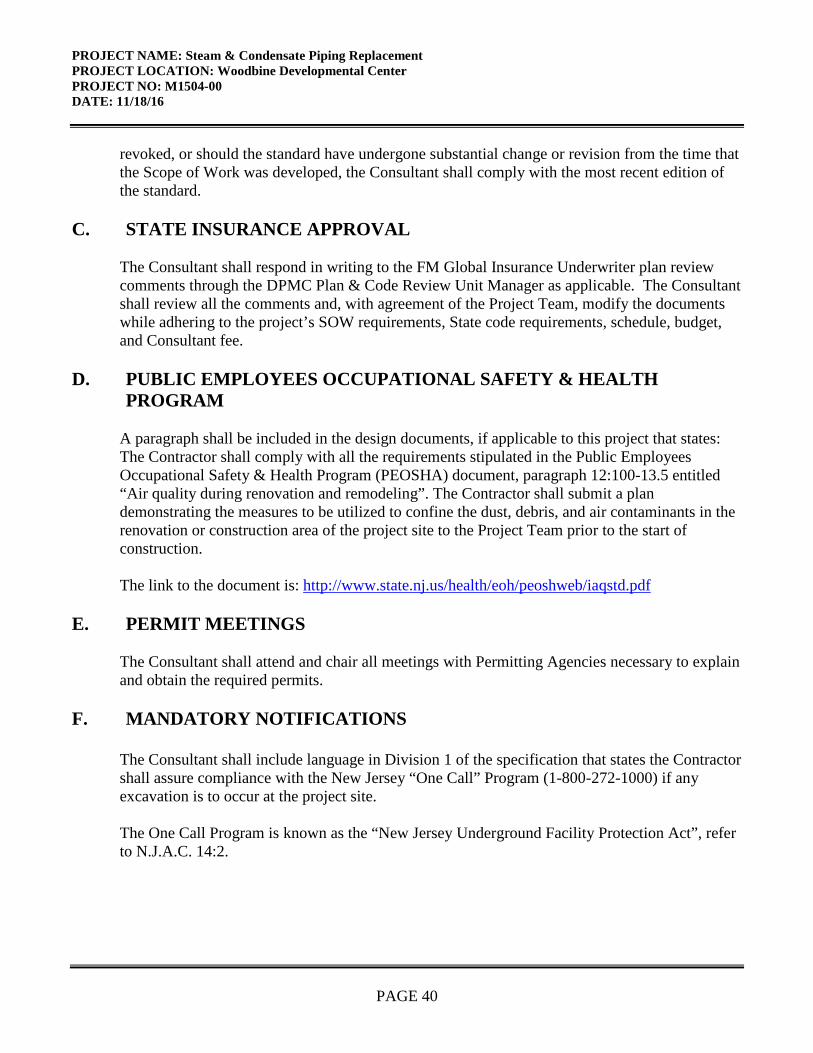
PROJECT NAME: Steam & Condensate Piping Replacement PROJECT LOCATION: Woodbine Developmental Center PROJECT NO: M1504-00 DATE: 11/18/16
PAGE 40
revoked, or should the standard have undergone substantial change or revision from the time that the Scope of Work was developed, the Consultant shall comply with the most recent edition of the standard.
C. STATE INSURANCE APPROVAL
The Consultant shall respond in writing to the FM Global Insurance Underwriter plan review comments through the DPMC Plan & Code Review Unit Manager as applicable. The Consultant shall review all the comments and, with agreement of the Project Team, modify the documents while adhering to the project’s SOW requirements, State code requirements, schedule, budget, and Consultant fee.
D. PUBLIC EMPLOYEES OCCUPATIONAL SAFETY & HEALTH PROGRAM
A paragraph shall be included in the design documents, if applicable to this project that states: The Contractor shall comply with all the requirements stipulated in the Public Employees Occupational Safety & Health Program (PEOSHA) document, paragraph 12:100-13.5 entitled “Air quality during renovation and remodeling”. The Contractor shall submit a plan demonstrating the measures to be utilized to confine the dust, debris, and air contaminants in the renovation or construction area of the project site to the Project Team prior to the start of construction. The link to the document is: http://www.state.nj.us/health/eoh/peoshweb/iaqstd.pdf
E. PERMIT MEETINGS The Consultant shall attend and chair all meetings with Permitting Agencies necessary to explain and obtain the required permits.
F. MANDATORY NOTIFICATIONS The Consultant shall include language in Division 1 of the specification that states the Contractor shall assure compliance with the New Jersey “One Call” Program (1-800-272-1000) if any excavation is to occur at the project site. The One Call Program is known as the “New Jersey Underground Facility Protection Act”, refer to N.J.A.C. 14:2.

PROJECT NAME: Steam & Condensate Piping Replacement PROJECT LOCATION: Woodbine Developmental Center PROJECT NO: M1504-00 DATE: 11/18/16
PAGE 41
G. CONSULTANT FEE
The Consultant shall determine the efforts required to complete and submit all permit applications, obtain and prepare supporting documentation, attend meetings, etc., and include the total cost in the base bid of their fee proposal under the “Permit Phase”.
X. GENERAL REQUIREMENTS
A. SCOPE CHANGES
The Consultant must request any changes to this Scope of Work in writing. An approved DPMC 9d Consultant Amendment Request form reflecting authorized scope changes must be received by the Consultant prior to undertaking any additional work. The DPMC 9d form must be approved and signed by the Director of DPMC and written authorization issued from the Project Manager prior to any work being performed by the Consultant. Any work performed without the executed DPMC 9d form is done at the Consultant’s own financial risk.
B. ERRORS AND OMISSIONS
The errors and omissions curve and the corresponding sections of the “Procedures for Architects and Engineers Manual” are eliminated. All claims for errors and omissions will be pursued by the State on an individual basis. The State will review each error or omission with the Consultant and determine the actual amount of damages, if any, resulting from each negligent act, error or omission.
C. ENERGY INCENTIVE PROGRAM
The Consultant shall review the programs described on the “New Jersey’s Clean Energy Program” website at: http://www.njcleanenergy.com to determine if any proposed upgrades to the mechanical and/or electrical equipment and systems for this project qualify for “New Jersey Clean Energy Program” rebates and incentives such as SmartStart, Pay4Performance, Direct Install or any other incentives.
The Consultant shall be responsible to complete the appropriate registration forms and applications, provide any applicable worksheets, manufacturer’s specification sheets, calculations, attend meetings, and participate in all activities with designated representatives of the programs and utility companies to obtain the entitled financial incentives and rebates for this project. All costs associated with this work shall be estimated by the Consultant and the amount included in the base bid of their fee proposal.
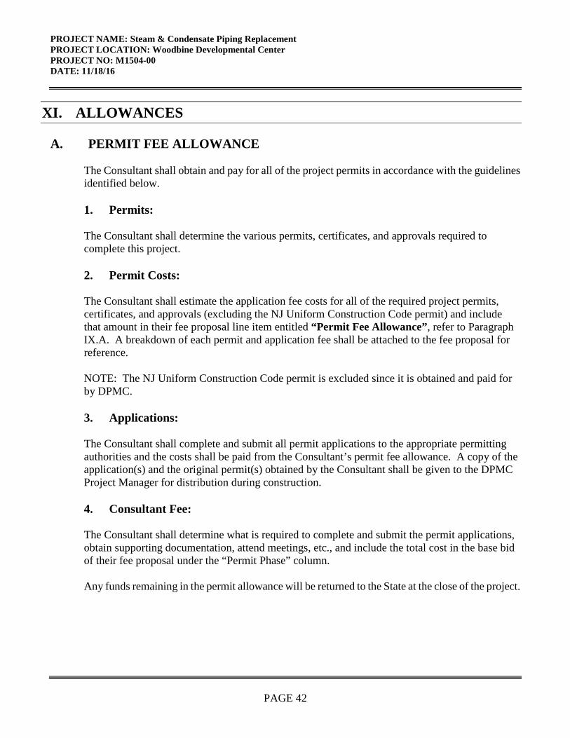
PROJECT NAME: Steam & Condensate Piping Replacement PROJECT LOCATION: Woodbine Developmental Center PROJECT NO: M1504-00 DATE: 11/18/16
PAGE 42
XI. ALLOWANCES
A. PERMIT FEE ALLOWANCE
The Consultant shall obtain and pay for all of the project permits in accordance with the guidelines identified below.
1. Permits:
The Consultant shall determine the various permits, certificates, and approvals required to complete this project.
2. Permit Costs:
The Consultant shall estimate the application fee costs for all of the required project permits, certificates, and approvals (excluding the NJ Uniform Construction Code permit) and include that amount in their fee proposal line item entitled “Permit Fee Allowance”, refer to Paragraph IX.A. A breakdown of each permit and application fee shall be attached to the fee proposal forreference.
NOTE: The NJ Uniform Construction Code permit is excluded since it is obtained and paid for by DPMC.
3. Applications:
The Consultant shall complete and submit all permit applications to the appropriate permitting authorities and the costs shall be paid from the Consultant’s permit fee allowance. A copy of the application(s) and the original permit(s) obtained by the Consultant shall be given to the DPMC Project Manager for distribution during construction.
4. Consultant Fee:
The Consultant shall determine what is required to complete and submit the permit applications, obtain supporting documentation, attend meetings, etc., and include the total cost in the base bid of their fee proposal under the “Permit Phase” column.
Any funds remaining in the permit allowance will be returned to the State at the close of the project.
PROJECT NAME: Steam & Condensate Piping Replacement PROJECT LOCATION: Woodbine Developmental Center PROJECT NO: M1504-00 DATE: 11/18/16
PAGE 43
B. HAZARDOUS MATERIALS ALLOWANCE
The Sub-Consulting firm(s) selected by the Consultant to conduct the hazardous materials tests, prepare the potential design documents, and provide construction administration services shall estimate all of the costs associated with their work and submit that amount to the Consultant prior to the proposed due date.
The Consultant shall enter the amount submitted by the Sub-Consulting firm(s) on the fee proposal line item entitled “Hazardous Materials Allowance” and attach a detailed cost breakdown sheet for use by the Project Team members during the proposal review and potential fee negotiations.
XII. SUBMITTAL REQUIREMENTS
A. CONTRACT DELIVERABLES
All submissions shall include the Contract Deliverables identified in Section XIV of this Scope of Work and described in the DPMC Procedures for Architects and Engineers Manual.
B. CATALOG CUTS
The Consultant shall provide catalog cuts as required by the DPMC Plan & Code Review Unit during the design document review submissions. Examples of catalog cuts include, but are not limited to: mechanical equipment, hardware devices, plumbing fixtures, fire suppression and alarm components, specialized building materials, electrical devices, etc.
C. PROJECT DOCUMENT BOOKLET
The Consultant shall submit all of the required Contract Deliverables to the Project Manager at the completion of each phase of the project. All reports, meeting minutes, plan review comments, project schedule, cost estimate in CSI format (2004 Edition), correspondence, calculations, and other appropriate items identified on the Submission Checklist form provided in the A/E Manual shall be presented in an 8½” x 11” bound “booklet” format.
D. DESIGN DOCUMENT CHANGES
Any corrections, additions, or omissions made to the submitted drawings and specifications at the Permit Phase of the project must be submitted to DPMC Plan & Code Review Unit as a complete document. Corrected pages or drawings may not be submitted separately unless the

PROJECT NAME: Steam & Condensate Piping Replacement PROJECT LOCATION: Woodbine Developmental Center PROJECT NO: M1504-00 DATE: 11/18/16
PAGE 44
Consultant inserts the changed page or drawing in the original documents. No Addendums or Bulletins will be accepted as a substitution to the original specification page or drawing.
E. SINGLE-PRIME CONTRACT
All references to “separate contracts” in the Procedures for Architects and Engineers Manual, Chapter 8, shall be deleted since this project will be advertised as a “Single Bid” (Lump Sum All Trades) contract. The single prime Contractor will be responsible for all work identified in the drawings and specifications.
The drawings shall have the required prefix designations and the specification sections shall have the color codes as specified for each trade in the DPMC Procedure for Architects and Engineers Manual.
The Consultant must still develop the Construction Cost Estimate (CCE) for each trade and the amount shall be included on the DPMC-38 Project Cost Analysis form where indicated. This document shall be submitted at each design phase of the project and updated immediately prior to the advertisement to bid.


PROJECT NAME: Steam & Condensate Piping Replacement PROJECT LOCATION: Woodbine Developmental Center PROJECT NO: M1504-00 DATE: 11/18/16
PAGE 46
XIV. CONTRACT DELIVERABLES The following is a listing of Contract Deliverables that are required at the completion of each phase of this project. The Consultant shall refer to the DPMC publication entitled, “Procedures for Architects and Engineers,” Volumes I and II, 2nd Edition, dated January, 1991 to obtain a more detailed description of the deliverables required for each item listed below. The numbering system used in this “Contract Deliverables” section of the scope of work corresponds to the numbering system used in the “Procedures for Architects and Engineers” manual and some may have been deleted if they do not apply to this project. SCHEMATIC DESIGN PHASE: 25% Complete Design Documents (Minimum) 6.1 Project Schedule (Update Bar Chart Schedule) 6.2 Meetings & Minutes (Minutes within seven (7) calendar days of meeting) 6.2.1 Working Design Meeting (1) w/Project 6.3 Correspondence 6.4 Submission Requirements 6.4.1 A/E Statement of Site Visit, As-Built Drawing Verification (if available) 6.4.2 Surveys 6.4.2.1 Site Topographic Survey 6.4.2.2 Building Survey 6.4.2.3 Underground Utility Survey 6.4.2.4 Heating Boiler, Steam Line Header, Deareator Survey 6.4.2.5 Mechanical Equipment Survey 6.4.2.6 Pressure Reducing Station Survey 6.4.2.7 Water-table Survey 6.4.3 Special Features Description: communications, security, smoke, exhaust, fire
protection, special structural features, etc. 6.4.4 Site Evaluation 6.4.5 Borings, Surveys, and Soils Analysis (provided with plan submission) 6.4.8 Regulatory Agency Approvals 6.4.8.1 NJ Department of Agriculture (a) Soil Erosion (land disturbance over 5000 s.f.) 6.4.8.2 NJ Department of Community Affairs

PROJECT NAME: Steam & Condensate Piping Replacement PROJECT LOCATION: Woodbine Developmental Center PROJECT NO: M1504-00 DATE: 11/18/16
PAGE 47
(a) UCC Permit for Building Construction 6.4.9 Utility Availability for: Electric Service 6.4.10 Drawings: 6 sets Cover Sheet (See A/E Manual for format) Site Plan Site Utility Plan Floor Plans Elevations Sections/Details Structural Narrative HVAC Narrative Electrical Narrative 6.4.11 Specifications: 6 sets (See A/E Manual for format, include Division 1 and edit to
describe the administrative and general requirements of the project) 6.4.12 Current Working Estimate in CSI Format & Cost Analysis 38 Form 6.4.13 Bar Chart of Design and Construction Schedule 6.4.14 Oral Presentation of Submission to Project Team 6.4.15 SOW Compliance Statement 6.4.16 This Submission Checklist (See A/E Manual, Figure 6.4.16 for format) 6.4.17 Deliverables Submission in Booklet Form: 7 sets 6.5 Approval 6.5.1 Respond to Submission Comments 6.6 Submission Forms Figure 6.4.10 Plan Review Record Sheet Figure 6.4.12 Current Working Estimate/Cost Analysis Figure 6.4.16 Submission Checklist DESIGN DEVELOPMENT PHASE: 50% Complete Design Documents (Minimum) 7.1 Project Schedule (Update Bar Chart Schedule) 7.2 Meetings & Minutes (Minutes within seven (7) calendar days of meeting) 7.2.1 Working Design Meeting (2) w/Project Team Members 7.3 Correspondence 7.4 Submission Requirements

PROJECT NAME: Steam & Condensate Piping Replacement PROJECT LOCATION: Woodbine Developmental Center PROJECT NO: M1504-00 DATE: 11/18/16
PAGE 48
7.4.1 A/E Statement of Site Visit, As-Built Drawing Verification (if available) 7.4.4 Site Evaluation 7.4.5 Borings, Surveys, and Soils Analysis (provided with plan submission) 7.4.8 Regulatory Agency Approvals (See Section 6.4.8 for listing) 7.4.10 Drawings: 6 sets Cover Sheet (See A/E Manual for format) Piping distribution & riser details, signed & sealed calculations 7.4.11 Specifications: 6 sets (See A/E Manual for format, include Division 1 and edit to Describe the administrative and general requirements of the project) 7.4.12 Current Working Estimate in CSI Format & Cost Analysis 38 Form 7.4.13 Bar Chart of Design and Construction Schedule 7.4.14 Oral Presentation of Submission to Project Team 7.4.15 SOW Compliance Statement 7.4.16 This Submission Checklist (See A/E Manual, Figure 6.4.16 for format) 7.4.17 Deliverables Submission in Booklet Form: 7 sets 7.5 Approval 7.5.1 Respond to Submission Comments 7.6 Submission Forms Figure 7.4.12 Current Working Estimate/Cost Analysis Figure 7.4.16 Submission Checklist FINAL DESIGN PHASE 100% Complete Construction Documents This Final Design Phase may require more than one submission based on the technical quality and code conformance of the design documents. 8.1 Schedule (Update Bar Chart Schedule) 8.2 Meeting & Minutes (Minutes within seven (7) calendar days of meeting) 8.2.1 Working Design Meetings (2) w/Project Team Members 8.3 Correspondence 8.4 Submission Requirements 8.4.1 A/E Statement of Site Visit 8.4.8 Regulatory Agency Approvals (Include itemized list specific to this project)
PROJECT NAME: Steam & Condensate Piping Replacement PROJECT LOCATION: Woodbine Developmental Center PROJECT NO: M1504-00 DATE: 11/18/16
PAGE 49
8.4.10 Drawings: 6 sets 8.4.11 Specifications: 6 sets 8.4.12 Current Working Estimate in CSI Format & Cost Analysis 38 Form 8.4.13 Bar Chart of Design and Construction Schedule 8.4.14 Oral Presentation of this Submission to Project Team 8.4.15 Plan Review/SOW Compliance Statement 8.4.16 This Submission Checklist 8.4.17 Deliverables Submission in Booklet Form: 7 sets 8.5 Approvals 8.5.1 Respond to Submission Comments PERMIT APPLICATION PHASE This Permit Application Phase should not include any additional design issues. Design documents shall be 100% complete at the Final Design Phase. 8.6 Permit Application Submission Requirements 8.6.8 Regulatory Agency Approvals (a) UCC Permit Application & Technical Sub-codes completed by A/E 8.6.9 Utility Availability Confirmation 8.6.10 Signed and Sealed Drawings: 6 sets 8.6.11 Signed and Sealed Specifications: 6 sets 8.6.12 Current Working Estimate/Cost Analysis 8.6.14 Project Presentation (N/A this Project) 8/6.16 Submission Checklist 8.7 Approvals 8.8 Submission Forms Figure 8.4.12 Current Working Estimate/Cost Analysis Figure 8.4.16 Submission Checklist (Final Review Phase) Figure 8.6.12-b Bid Proposal Form (Form DPMC -3) Figure 8.6.12-c Notice of Advertising (Form DPMC -31) Figure 8.6.16 Submission Checklist (Permit Phase) Figure 8.7 Bid Clearance Form (Form DPMC -601) BIDDING AND CONTRACT AWARD

PROJECT NAME: Steam & Condensate Piping Replacement PROJECT LOCATION: Woodbine Developmental Center PROJECT NO: M1504-00 DATE: 11/18/16
PAGE 50
9.0 Bidding Phase Requirements
9.01 Original Drawings signed & sealed by A/E and drawings on compact disk (CD) in Adobe Portable Document Format (.pdf) 9.02 One Unbound Specification Color Coded per A/E Manual Section 8.4.11 and
specifications on compact disk (CD) in Adobe Portable Document Format (.pdf) ` 9.03 Bid Documents Checklist 9.04 Bid Proposal Form 9.05 Notice for Advertising 9.1 Chair Pre-Bid Conference/Mandatory Site Visit 9.1.1 Prepare & Distribute Pre-Bid Minuets 9.2 Prepare Bulletins 9.3 Attend Bid Opening 9.4 Recommendation for Contract Award 9.4.1 Prepare Letter of Recommendation for Award & Cost Analysis 9.5 Attend Pre-Construction Meeting 9.6 Submission Checklist 9.7 Submission Forms Figure 9.4.1 Cost Analysis Figure 9.6 Submission Checklist CONSTRUCTION PHASE 10.1 Site Construction Administration 10.2 Pre-Construction Meeting 10.3 Construction Job Meetings 10.3.1 Agenda: Schedule and Chair Construction Job Meetings 10.3.2 Minutes: Prepare and Distribute Minutes within 5 working days of meeting 10.3.3 Schedules; Approve Contractors’ Schedule & Update

PROJECT NAME: Steam & Condensate Piping Replacement PROJECT LOCATION: Woodbine Developmental Center PROJECT NO: M1504-00 DATE: 11/18/16
PAGE 51
10.3.4 Minutes Format: Prepare Job Meeting Minutes in approved format, figure 10.3.4-a 10.4 Correspondence 10.5 Prepare and Deliver Conformed Drawings 10.7 Approve Contractors Invoicing and Payment Process 10.8 Approve Contractors 12/13 Form for Subs, Samples and Materials 10.10 Approve Test Reports 10.11 Approve Shop Drawings 10.12 Construction Progress Schedule 10.12.1 Construction Progress Schedule 10.12.2 CPM Consultant 10.13 Review & Recommend or Reject Change Orders 10.13.1 Scope Changes 10.13.2 Construction Change Orders 10.13.3 Field Changes 10.14 Construction Photographs 10.15 Submit Field Observation Reports 10.16 Submission Forms Figure 10.3.4-a Job Meeting Format of Minutes Figure 10.3.4-b Field Report Figure 10.6 DPMC Insurance Form-24 Figure 10.6-a Unit Schedule Breakdown Figure 10.6-b Monthly Estimate for Payment to Contractor DPMC 11-2 Figure 10.6-c Monthly Estimate for Payment to Contractor DPMC 11-2A Figure 10.6-d Invoice DPMC 11 Figure 10.6-e Prime Contractor Summary of Stored Materials DPMC 11-3 Figure 10.6-f Agreement & Bill of Sale certificate for Stored Materials DPMC 3A Figure 10.7-a Approval Form for Subs, Samples & Materials DPMC 12 Figure 10.7-b Request for Change Order DPMC 9b

PROJECT NAME: Steam & Condensate Piping Replacement PROJECT LOCATION: Woodbine Developmental Center PROJECT NO: M1504-00 DATE: 11/18/16
PAGE 52
Figure 10.9 Transmittal Form DPMC 13 Figure 10.10 Submission Checklist PROJECT CLOSE-OUT PHASE 11.1 Responsibilities: Plan, Schedule and Execute Close-Out Activities 11.2 Commencement: Initiate Close-Out w/DPMC 20A Project Close-Out Form 11.3 Develop Punch List & Inspection Reports 11.4 Verify Correction of Punch List Items 11.5 Determination of Substantial Completion 11.6 Ensure Issuance of “Temporary Certificate of Occupancy or Approval” 11.7 Initiation of Final Contract Acceptance Process 11.8 Submission of Close-Out Documentation 11.8.1 As-Built & Record Set Drawings, 3 sets AUTOCAD Discs Delivered to DPMC 11.8.2 (a) Maintenance and Operating manuals, Warranties, etc.: 7 sets each (b) Guarantees (c) Testing and Balancing Reports (d) Boiler Inspection Certificates (e) Shop Drawings (f) Letter of Contract Performance 11.8.3 Final Cost Analysis-Insurance Transfer DPMC 25 11.8.4 This Submission Checklist 11.9 Final Payment 11.9.1 Contractors Final Payment 11.9.2 A/E Invoice and Close-Out Forms for Final Payment 11.10 Final Performance Evaluation of the A/E and the Contractors 11.11 Ensure Issuance of a “Certificate of Occupancy or Approval” 11.12 Submission Forms Figure 11.2 Project Close-Out Documentation List DPMC 20A

PROJECT NAME: Steam & Condensate Piping Replacement PROJECT LOCATION: Woodbine Developmental Center PROJECT NO: M1504-00 DATE: 11/18/16
PAGE 53
Figure 11.3-a Certificate of Substantial Completion DPMC 20D Figure 11.3-b Final Acceptance of Consultant Contract DPMC 20C Figure 11.5 Request for Contract Transition Close-Out DPMC 20X Figure 11.7 Final Contract Acceptance Form DPMC 20 Figure 11.8.3-a Final Cost Analysis Figure 11.8.3-b Insurance Transfer Form DPMC 25 Figure 11.8.4 Submission Checklist
XV. EXHIBITS The attached exhibits in this section will include a sample project schedule, and any supporting documentation to assist the Consultant in the design of the project such as maps, drawings, photographs, floor plans, studies, reports, etc.
END OF SCOPE OF WORK

February 7, 1997Rev.: January 29, 2002
Responsible Group Code Table
The codes below are used in the schedule field “GRP” that identifies the group responsible for theactivity. The table consists of groups in the Division of Property Management & Construction(DPMC), as well as groups outside of the DPMC that have responsibility for specific activities ona project that could delay the project if not completed in the time specified. For reportingpurposes, the groups within the DPMC have been defined to the supervisory level ofmanagement (Le., third level of management, the level below the Associate Director) to identifythe “functional group” responsible for the activity.
CODE DESCRIPTION REPORTS TO ASSOCIATE DIRECTOR OF:
CM Contract Management Group Contract Management
CA Client Agency N/A
CSP Consultant Selection and Technical ServicesPrequalification Group
NE Architect/Engineer N/A
PR Plan Review Group Technical Services
CP Construction Procurement Planning & Administration
CON Construction Contractor N/A
FM Financial Management Group Planning & Administration
OEU Office of Energy and N/AUtility Management
PD Project Development Group Planning & Administration
EXHIBIT ‘A’
Page 1 of 4

Act
ivity
Ix
tesc
ar.p
ti.n
ii,,
ni
,,,,u.in,,,,,
i,a
it,i
pi.
agn.
;..itu.n
.ii
i.
iiii
,i
in.
mii
i...
..
ii.
Iq
uin
tnin
imi
IH
tiii
.,.u
i.p..
.ini
,nni,
nrn
ii,.in
.ni
ii
h Des
CV
3)l
Sche
dule
/Con
duct
Predesign/P
roject
Kic
kO
ffM
tgC
M
CV
3020
Prep
are
Program
Phas
eSu
bmitt
alA
E
CV
3021
Dis
trib
ute
Prog
ram
Subm
ittal
for
Rev
iew
CM
CV
3OZI
Prep
are
&Su
bmit
Prbj
ect
Cos
t Analy
sis
(DPM
C38
)C
M
CV
3022
Rev
iew
&A
pprove
Program
Subm
ittal
CA
CV
3023
Revie
w&
Approve
Program
Subm
ittal
PR
CVSO
24R
evie
w&
Approve
Program
Subm
ittal
CM
CV
3025
Con
solid
ate
&R
etur
nPr
ogra
mSu
bmitt
alC
omm
ents
CM
CV
3030
Prep
are
Sche
mat
icPh
ase
Subm
ittal
AE
CV
3031
Dis
trib
ute
Sche
mat
icSu
bmitt
alfo
rR
evie
wC
M
CV
3037
Prep
are
&Su
bmit
Proj
ect
Cos
tAna
lysi
s(D
PMC
38)
CM
CVSO
3ZR
evie
w&
App
rove
Sche
mat
icSu
bmitt
alC
A
CV
3033
Rev
iew
&A
ppro
veSc
hem
atic
Subm
ittal
PR
Rev
iew
&A
ppro
veSc
hem
atic
Subm
ittal
CM
CV
3035
Con
solid
ate
&R
etur
nSc
hem
atic
Subm
ittal
Com
men
tC
M
CV
3040
Pre
pare
Des
ignD
evel
opm
entP
hase
Sub
mit
tal
AE
CV3O
S1D
istr
ibut
eD
DSu
bmitt
alfo
rR
evie
wC
M
C’O
47Pr
epar
e&
Subm
itPr
ojec
tCos
t Ana
lysi
s(D
PMC
38)
CM
CV
3042
Rev
iew
&A
ppro
veD
esig
nD
evel
opm
ent S
ubm
ittal
CA
CV
3043
Rev
iew
&A
ppro
veD
esig
nD
evel
opm
ent S
ubm
ittal
PRC
’130
44R
evie
w&
App
rove
Des
ign
Dev
elop
men
tSu
bmitt
alC
MCV
SO45
Con
solj
date
&R
etum
DD
.Sub
mit
talC
omm
ents
CM
Prep
are
Fina
lD
esig
nPh
ase
Subm
ittal
AE
CV3O
SID
istr
ibut
eFi
nal
Des
ign
Subm
ittal
for
Rev
iew
CM
CV
3052
Rev
iew
&A
ppro
veFi
nal
Des
ign
Subm
ittal
CA
CV
3053
Rev
iew
&A
ppro
veFi
nal
Des
ign
Subm
ittal
PRC
V30
54R
evie
wFi
nal
Des
ign
Subm
itifo
rC
onst
ruct
abili
tyO
CS
:N
OT
E:
DB
cA.T
FS
TS
heti
of3
Ref
erto
sect
ion
“IV
Pro
ject
Sch
edul
e”of
the
Bur
eau
ofD
esig
n&
Con
stru
ctio
nS
ervi
ces
Sco
peof
Work
for
contr
act
phas
edu
rati
ons.
Rou
tine
Pro
ject
IX
h1b
it‘
iS0
Prl
mav
era
Sys
tem
s,In
c.
Page 2 of 4

Act
ivit
y.
II)
L)e
seri
pti
on
‘R
evie
w&
App
rove
Fina
lD
esig
nSu
bmitt
alC
M
‘3
0C
onso
lidat
e&
Ret
urn
Fina
lDes
ign
Com
men
tsC
M
Prep
are
&Su
bmit
Perm
itA
pplic
atio
nD
ocum
ents
AE
CV
3068
Prep
are
&Su
bmit
Bid
ding
Cos
tAna
lysi
s(D
PMC
38)
CM
Pla
nR
evie
w-P
ernz
ztA
cgw
stho
nC
V40
0iR
evie
wC
onst
rD
ocum
ents
&Se
cure
UC
CPe
rmit
PR
CV4O
1OPr
ovid
eFu
ndin
gfo
rC
onst
ruct
ion
Con
trac
tsC
A
CV
4020
Secu
reB
idC
lear
ance
CM
Adv
ertis
e-B
id-A
war
dC
V50
0IA
dver
tise
Proj
ect&
Bid
Con
stru
ctio
nC
ontr
acts
CP
CV5O
IOO
pen
Con
stru
ctio
nB
ids
CP
CVSO
II
Eva
luat
eB
ids
&Pr
epR
ecom
men
datio
nfo
rA
war
dC
M
CV
5Oi2
Eva
luat
eB
ids
&Pr
epR
ecom
men
datio
nfo
rA
war
dA
E
CV
5Oi4
Com
plet
eR
ecom
men
datio
nfo
rAw
ard
CP
CV
5020
Aw
ardC
onst
ruct
ionC
ontr
acts
/lss
ueN
TP
CP
:
Con
sfru
ctio
nC
’P
roje
ctC
onst
ruct
ion
Slar
tfls
sue
NT
PC
M
CV
6mi
Con
trac
tSta
rtlC
ontr
actW
ork
(25%
)C
ompl
ete
CO
N
CV
tOO
2Pr
econ
stru
cuon
Mee
ting
CM
CV
t()03
Beg
inPr
econ
stru
ctio
nSu
bmitt
als
CO
N
CVI5
004
Lon
gest
Lea
dPr
ocur
emen
tIte
mO
rder
edC
ON
CVtO
OS
Lea
dT
ime
for
Lon
gest
Lea
dPr
ocur
emen
tIt
emC
ON
Prep
are
&Su
bmit
Shop
Dra
win
gsC
ON
CV
6007
Com
plet
eC
onst
ruct
ion
Subm
ittal
sC
ON
CVSO
I IR
ough
ing
Wor
kSt
art
CO
N
CV
eoia
Perf
orm
Rou
ghin
gW
ork
CO
N
CVSO
IOC
ontr
actW
ork
(50%
+)C
ompl
ete
CO
N
CV
tOt3
Lon
gest
Lea
dPr
ocur
emen
tIte
mD
eliv
ered
CO
N
“°
Con
trac
tW
ork
(75%
)C
ompl
ete
CO
N
NO
TE
:D
BC
AT
ES
TSl
ieet
2or3
Ref
erto
sect
ion
“IV
Pro
ject
Sche
dule
”of
the
Bur
eau
ofD
esig
n&
Con
stru
ctio
nSe
rvic
esSc
ope
ofW
ork
for
cont
ract
phas
edu
rati
ons.
Rou
tine
Pro
ject
1xli
i I)i
t@
Pil
mav
era
Syst
ems,
Inc.
Page 3 of 4

Act
ivity
11)
-
t)es
crip
tion
si)r
.C
VO
14R
ough
ing
Wor
kC
ompl
ete
CO
N
CV
6021
Inte
rior
Fini
shes
Star
tC
ON
CV
)22
Inst
all
Inte
rior
Fini
shes
CO
N
CV
O3O
Con
trac
tWor
kto
Subs
tant
ialC
ompl
etio
nC
ON
(DV
O3l
Subs
tant
ialC
ompl
etio
nD
ecla
red
CM
CVC’
075
Com
plet
eD
efer
red
Punc
hL
ist)
Seas
onal
Act
iviti
esC
OI4
CV
6079
Proj
ectC
onst
ruct
ion
Com
plet
eC
M:
CV60
84)
Clo
seO
utC
onst
ruct
ion
Con
trac
tsC
M
CV
6O&
Con
stru
ctio
nC
ontr
acts
Com
plet
eC
M
CV6O
SOC
lose
Out
A/E
Con
trac
tC
M
CV
6092
Proj
ectC
ompl
etio
nD
ecla
red
CM
NO
TE
:D
BC
AT
ES
TS
hee
t3of3
Ref
erto
sect
ion
“IV
Pro
ject
Sche
dule
”of
the
Bure
auof
Des
ign
&C
onst
ruct
ion
Ser
vic
esSc
ope
ofW
ork
for
cont
ract
phas
edu
ratio
ns.
Routi
ne
Pro
ject
Ixli
i bit
‘
©P
rim
aver
aS
yste
ms,
Inc.
Page 4 of 4
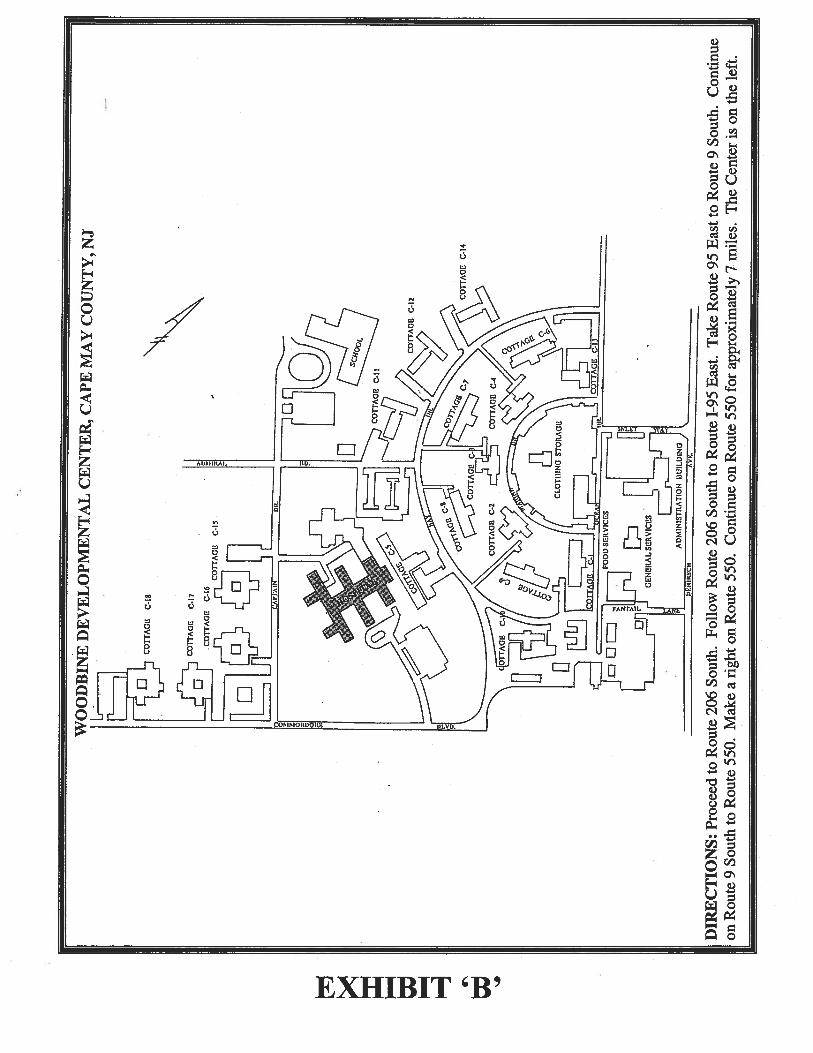

Woodbine Developmental Center – Engineering Department A. GENERAL SITE REGULATIONS
UNLESS OTHERWISE SPECIFIED IN THE SOW, THE FOLLOWING REPRESENTS THE GUIDELINES FOR WORK PERFORMED AT WOODBINE DEVELOPMENTAL CENTER.
1. Contractors and their Employees are authorized to be on grounds only during the performance of work related to the project.
2. The speed limit is 15 mph on grounds. Yield to all pedestrian traffic. Resident population is severely handicapped, some are blind, some are deaf; many do not possess good pedestrian skills.
3. Do not give anything to a resident. This includes food, money and cigarettes. 4. It is not permitted to photograph any resident. 5. Smoking is permitted in designated areas only. Matches and cigarette butts pose a life threatening danger to some
of our residents and must be disposed in an appropriate receptacle. 6. Contractor will be responsible to police the construction area keeping it free of debris and litter. 7. Vehicles and operating equipment is to be off and secure whenever not in use. All tools and equipment are to be
secured at the end of the work day. If kept on site, they must be stored within a fenced work staging area. WDC will not assume responsibility for any missing articles.
8. To minimize the disruption to unexcavated areas and enhance the protection of fragile underground utilities, ground mats are to be used if heavy equipment (cranes, tractor trailers, dumpsters) is expected to travel over or operate from unpaved areas.
9. Active construction, staging and equipment storage areas are to be fenced and secured (6 foot chain link preferred) at all times to prevent residents and employees from wandering inside.
10. Possession and/or consumption of alcoholic beverages or drugs are prohibited, by law, anywhere on State property.
11. Please Note: As available, prints of the site’s utilities may have been provided by the facility. Understand that the prints are general and that we have encountered situations where they are not accurate. Contractor should determine the actual location of any utility within the construction zone.
B. HOURS OF WORK
1. Work will occur Monday through Friday only. Any work on Saturday, Sunday, or state Holiday must be approved by the project coordinator and the WDC Engineering Office. A two day (48 hour) notice is required.
2. Project work will not begin before 7:30am.
3. WDC Engineering Office is to be notified whenever project work is to occur beyond 4:30pm. A two day (48 hour) notice is required. Approval for ongoing work which is required to be completed that day should be sought by project manager/site foreman as soon as he becomes aware of the need. Facility will work with project manager to accommodate unanticipated needs.
4. No work will occur past dusk without 48 hours notice and approval of the WDC Engineering Office.
5. The facility requires a minimum of 48 hours notice for any contractor operation such as large material deliveries, power tie-ins, etc, that will impact or potentially disrupt facility operations.
EXHIBIT ‘C’
CONTRACTOR’S USE OF PREMISES
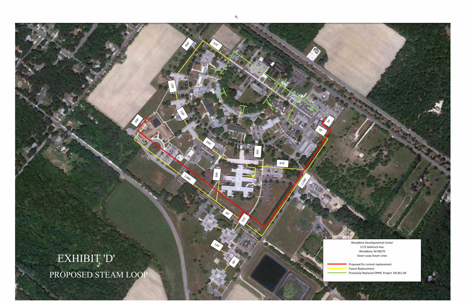
ɳ
Woodbine Developmental Center
1175 DeHirsch Ave.
Woodbine, NJ 08270
Outer Loop Steam Lines
Proposed for current replacement
Future Replacement
Previously Replaced DPMC Project M1361-00
EXHIBIT 'D'PROPOSED STEAM LOOP

EXHIBIT ‘E’ WOODBINE DEVELOPMENTAL CENTER LOCATION

Energy Assessment Woodbine Developmental CenterWoodbine, Cape May County, New Jersey
NEW JERSEY DEPARTMENT OF HUMAN SERVICES
Princeton Engineering Group, LLC 100A Forrestal Road
Princeton, New Jersey 08540
March 20, 2014
EXHIBIT 'F'

PE GROUP
Princeton Engineering Group, LLC
Consulting Engineers 100A Forrestal Road, Princeton, NJ 08540
Tel: (609) 243-9286 Fax: (609) 243-9287 e-mail: [email protected]
Woodbine Development Center Energy Assessment Systems Report Princeton Engineering Group, LLC 1 March 20, 2014
Central Boiler Plant Energy Assessment Woodbine Developmental Center
INTRODUCTION
Woodbine Developmental Center (WDC) is located on 250 acres of land in Woodbine, Cape May County. WDC provides a wide range of rehabilitation, behavioral and medical services and supports to persons with developmental disabilities. The complex consists of approximately 60 residential and service building structures located throughout the site.
The Princeton Engineering Group (PEG) has been retained to perform an energy assessment as required under the Area Source Boiler Rule, National Emission Standards for Hazardous Air Pollutants for Area Sources: Industrial, Commercial, and Institutional Boilers, 40 CFR Part 63. This report has been prepared in conformance with the requirements of Table 1- Energy Assessment Duration Requirements for annual boiler heat input less than 0.3 Tbtu/year
The majority of the buildings are provided with steam service piped from the Boiler Plant located in the Power House. The medium pressure steam at 65 psi generated in the Power House is distributed throughout the campus. Part of the steam piping is located in the underground service tunnels, while the remaining piping utilizes a direct burial application. The steam pressure is reduced utilizing pressure reducing valve (PRV) stations and then is sent to hot water converters in each building to generate hot water for heating. The steam is also used for domestic hot water service generation, laundry and food service. The medium pressure steam is used directly in two absorption chillers to generate chilled water for summer cooling.
A map of the existing steam distribution system is attached.
Princeton Engineering Group performed a visual inspection of the boiler systems during a site visit on March 7, 2014. An evaluation of operating characteristics, operating and maintenance procedure was performed and reviewed with operating personnel. An inventory of major energy use systems was completed. (See detailed breakdown below). In addition, a detailed review of available architectural and engineering plans, facility operation, maintenance procedures and logs (fuel usage) was performed as well.
PEG would like to thank Woodbine DC personnel for their assistance in provision of data and information for this report.

Woodbine Development Center Energy Assessment Systems Report Princeton Engineering Group, LLC 2 March 20, 2014
HEATING PLANT
The Central Heating Plant utilizes three Medium Pressure Steam Boilers:
• Boiler #1, water tube construction, manufactured by Nebraska Boiler division of Cleaver Brooks and rated at 40,000 lb of steam per hour;
• Boiler #2, fire tube construction, manufactured by Cleaver Brooks and rated at 24,000 lb of steam per hour;
• Boiler #3, fire tube construction, manufactured by Cleaver Brooks and rated at 17,000 lb of steam per hour.
All boilers utilize a common breeching connected to a 66 inch diameter round stack, 90 feet high. Boilers are designed for a dual fuel application and can be fired with either Gas or Oil. All boilers were recently replaced together with a condensate pump serving a portion of the distribution system. All other auxiliary equipment including flue and breeching were retained
ENERGY SOURCES
The boiler plant utilizes a combination of energy sources:
1. Land Fill Gas System (primary) 2. Natural Gas System (primary) 3. #2 Oil (back-up)
STEAM DISTRIBUTION
The WDC utilizes two independent loops for site steam piping distribution: Front and Back. The Front Loop has been recently replaced (2012) with a new piping system and is fully accessible in the walkable service tunnel. The Back Loop utilizes a shallow concrete surface trench covered with earth. Each trench is sloped toward the vault to allow for ground water drainage. Because the system is covered with earth, it is essentially not maintainable between valve vaults without major excavation. This system can tolerate some ground water saturation depending on the water tightness of construction and reliability of internal drainage.
BOILER SYSTEM EVALUATION
Boilers:
Boiler #1 is water tube design, has a heavy duty industrial grade construction and will provide a long operational life with very low maintenance requirements. The boiler utilizes membrane wall construction and does not require additional refractory, the gas seals are fully welded to ensure gas tight operation. Boilers #2 and #3 are Cleaver Brooks fire tube Steam Boilers. Due to a 4-pass, dry-back design they have high combustion efficiency and operate with a lower stack temperature as compared to a 2 or 3 pass equivalent sized boiler. All Boilers are well maintained and appear to be in good operating condition. A summary of the most recent available twelve month fuel consumption is attached.

Woodbine Development Center Energy Assessment Systems Report Princeton Engineering Group, LLC 3 March 20, 2014
Feedwater System:
A packaged deaerator is utilized. The deaerator is well maintained and is in good condition overall, two pump motors and some trim items were recently replaced due to wear and tear.
Combustion Air:
Combustion Air is sourced through the wall mounted outside air intake louver. In the attempt to improve the boilers combustion efficiency, a steam unit heater was installed in the front of the louver to preheat the combustion air.
Fuel System (including burners):
Boilers #2 and #3 are packaged boilers and are equipped with a manufacture provided burner. Boiler #1 has been provided with a special aftermarket burner design to fire landfill gas. (Special burner was required due to the highly corrosive nature of landfill gas). #2 oil is stored in (2) two 20,000 gallon above ground oil storage tanks and distributed by an oil pump set. Land fill gas is pumped to the site from the nearby landfill (about 2 miles away). The landfill gas quantity is limited and as a result it is mostly fired in the Boilers #2 and #3. The landfill gas is heavily laden with moisture and as result the boiler combustion efficiency when running on the land fill gas is quite low. However, the
Flue System:
All boilers utilize the common metal breeching attached to the brick stack. Due to the high moisture content of the landfill gas and low flue temperature, some of the condensation is formed in the breeching. Because the condensate is highly corrosive there is a visible damage to the breeching (rust spots at low points). This situation is also a detrimental to boiler #1 itself due to the backflow of the condensate in the boiler stack.
Blowdown System:
Boiler blow down is manually activated based on the conductivity measurements. Blow down is collected in the outside water storage tank and after cooling off the collected materials are sent to the facility's sewage treatment plant.
Combustion Control System:
All Boilers are equipped with a factory installed PLC based control system. The controls are optimized by the boiler manufacture to provide the best combustion efficiency possible for the selected operation parameters.
All boilers are manually stopped and started by the operator to suit the available fuel conditions.
Steam System:
Medium pressure steam is distributed throughout the site via an underground pipe distribution system. The front loop system is located in the accessible tunnel and available for inspection and repairs; it has been replaced recently and should not require any significant capital expenditure for the foreseeable

Woodbine Development Center Energy Assessment Systems Report Princeton Engineering Group, LLC 4 March 20, 2014
future. On the other hand, the back loop system dates to the 1970s, with some portions even older. It has a numerous leaks which are evident by the multiple steam clouds throughout the site. The loss of steam in the back loop system contributes to the significant water make up requirements and loss of boiler plant efficiency.
Condensate System:
The buildings are equipped with a steam converters; the condensate is collected and pumped back into the main condensate loop located in the tunnel. All condensate is drained back into the main condensate pump set (one for each loop) and then pumped back into the deaerator. Condensate piping is run in tandem with steam supply loops. Same problems are present: back loop condensate piping is leaking which leads to the loss of energy and requires a substantial amount of additional make up water. In addition, some steam traps are allowing the steam to enter the condensate piping, which can cause water hammer and damage to piping material in addition to energy loss.
The following is a listing of the major steam consuming buildings and equipment on campus. Steam consumption listed was obtained from design drawings; some estimates were made when such information was not available. Steam consumption given is the design peak rate.
MAJOR ENERGY USERS INVENTORY
User Steam consumption, lb./hr.
Absorption Chiller (new) 2100
Absorption Chiller (new) 2100
Cottage C15 1400
Cottage C16 1400
Cottage C17 1400
Cottage C18 1400
Cottage C1 850
Cottage C5 870
Cottage C7 900
Cottage C8 850
Cottage C9 850
Learning Center 4000
Administrative Building 850
Food service 2000
Laundry 1600 (estimated)

Woodbine Development Center Energy Assessment Systems Report Princeton Engineering Group, LLC 5 March 20, 2014
Hospital 2000 (estimated)
Cottage C11 900
CottageC12 900
Cottage C14 900
CottageC2 850
Cottage C3 850
Cottage C4 850
Gen. Service 600
Cottage C6 800
Cottage C19 800 (estimated)
Cottage C10 900 (estimated)
Total 27,000 lb. /hr.
Notes:
a. Other structures located on site do not use a significant amount of energy and therefore are excluded from this report.
b. The absorption chillers steam demand is not included in the estimated total number above. (Heating only operation)
The average steam demand during heating season operation is approximately equal to 27,000#/HR. Based on the 83% boiler combustion efficiency and additional 10% piping and heat transfer losses the estimated peak energy input required is (27,000 x 1040)/.83 x .9 = 37,600,000.000BTU/H or 1120 BHP.
ENERGY USE SYSTEMS EVALUATION
Facility heating:
Medium pressure steam is used to generate a hot water for the facility. Each building is equipped with a set of hot water converters and circulating pumps. The hot water is pumped to the terminal devices to provide building heating. Condensate is collected in the local condensate receiver and pumped back into the main return loop. Many of the buildings’ heating systems are dated and should be upgraded.
Domestic Hot Water:
The medium pressure steam is used to generate the domestic hot water. Because the heating medium is at higher pressure than the service water, the service water may be contaminated by leakage of the steam through the damaged heat exchanger. This system produces a very high rate of condensate, especially during peak demand, which puts a strain on the steam traps and return piping.

Woodbine Development Center Energy Assessment Systems Report Princeton Engineering Group, LLC 6 March 20, 2014
Facility Air Conditioning System:
The three existing single affect absorption chillers are being replaced with one centrifugal electric and two steam fired double effect absorption chillers. The new absorption chillers use 8.4 lb/hr of steam per Ton of refrigeration, compare to about 19 lb/hr for the old chillers. As a result the steam usage of the boiler plant will experience a significant reduction.
Food Preparation:
In commercial food preparation service, bacteria are usually killed by rinsing washed dishes with 180 to 195F hot water for several seconds. In addition, an ample supply of 150F water is required for the wash cycle of dishwashers. As a result food preparation requires a significant quantity of steam for it operation. Some of the flash steam and condensate can be used for the heat recovery as well.
Laundry:
Commercial laundries are ideally suited for heat recovery, because 135F wastewater is discharged to the sewer. Fresh water can be conservatively preheated to within 15F of the wastewater temperature for the next wash cycle. Also flash steam can be recovered to preheat makeup water to the heater by an additional 10 to 15F.
Building Envelope:
Most of the existing building structures date back to the 1970s, and were built to comply with energy conservation requirements, which were in force at that time. Current Building Energy Standards are very different today and require better roof and ceiling insulation, more energy efficient windows, etc. To improve overall building U-value, installation of an additional roof and wall insulation would be desirable.
RECOMMENDATIONS
Steam Distribution System:
The most important improvement which could be made would be to reduce leakage in the steam and condensate piping. Since the replacement of the Front Loop piping, the majority of the energy loss is a result of the steam and condensate leakage from the older Back loop distribution piping. Because most of the distribution loop is underground, finding the source of leakage and fixing it requires a major effort. As a result, a lot of leaks remain unattended, and continue to lose steam.
The facility has provided logs of makeup water requirements for the central steam system. While some leakage is to be expected in any steam system, the high makeup rates confirm that there is extensive leakage in the distribution piping.
The reported leakage varies widely, between several hundred to over 11,000 gallons per day. The average leakage for the reported 52 weeks is approximately 3500 gallons per day. Leakage can be expected to worsen as corrosion inevitably advances in the piping.

Woodbine Development Center Energy Assessment Systems Report Princeton Engineering Group, LLC 7 March 20, 2014
Leakage is occurring in both the steam and condensate piping. Energy waste is higher for steam leaks, since all the energy of the lost steam is wasted. Energy loss due to condensate leakage is much lower since the steam has already been used for heating and the lost energy is only that needed to heat the makeup water to the condensate return temperature. The cost at WDC would be between $20,000 and as high as $120,000 annually to compensate for the additional fuel required.
Based on the high end of makeup water requirements of 10,000 gal per day, we estimate that the facility is required to spend an estimated $50,000 to $60,000 per year for the lost energy. This is based on 50% lost condensate and 50% lost steam. While the payback in energy savings does not look positive given the replacement costs (see below), this cost will continue to increase and repair costs will rise so as to eventually be unsustainable.
Due to the age of Back Loop piping and based on ASHRAE life cycle analyses the distribution system should be replaced. There are two basic options available: aboveground system and underground system. An aboveground system has the lowest first cost and is the easiest to inspect and maintain, however it is susceptible to freezing, it could be a safety hazard and has a poor aesthetics. Because of all of these negative factors an aboveground system is not recommended. An underground system is much more desirable, but is more expensive to build. To reduce maintenance requirements and assure the longest possible service life, we recommend a prefabricated pipe conduit system. The steam and condensate piping would be within a single large conduit, each pipe would be individually insulated and the system would include a liquid sensing cable along the length of the conduit to detect leakage and pinpoint the location to facilitate repair. The field work will be required for trenching, backfilling, valve vaults and connecting to buildings. We have estimated that Back loop replacement will require installation of around 6000 L.F of new conduit system. Based on an estimated cost of $500 per LF, total installed cost would be in the $3,000,000 range.
Surface Blow down Heat Recovery:
This option is not recommended due to the very corrosive properties of liquid and intermediate blow down operation.
Feed Water Heat Recovery:
Install feed water heat recovery equipment on both fire tube boilers. This option is recommended not only because of energy recovery, but to protect water tube boiler from the corrosion as well. This option will require installation of new stacks for both fire tube boilers. The existing breeching is in poor condition and should be replaced with a new one designed to service the water tube boiler only. This option will provide an additional operation redundancy and will allow chimney cleaning and soot removal without shutting down the entire boiler plant operation. Based on the vendor quotation the budget price for this option is around $300,000. The rate of heat recovery will vary depending on quantity of fresh water make up requirements. Utilizing currently available data it is estimated that simple pay back for this option will be around 5 years. Note that this is based on the current high

Woodbine Development Center Energy Assessment Systems Report Princeton Engineering Group, LLC 8 March 20, 2014
makeup water requirements. If the makeup water usage is significantly reduced as a result of large scale repairs, the payback period for heat recovery would be extended.
General Maintenance Recommendations:
Check the refractory for integrity to ensure it is properly protecting critical portions of the boiler. Check for broken pieces or even cracks, and repair if needed.
Check oil fuel feed system and burners. Clean or replace any fuel filters to maintain effective fuel flow.
Clean boiler heat transfer surfaces regularly to remove buildup of soot. Soot can act as an insulator which cuts down on the efficiency of the heat transfer between combustion gas and steam generation.
Repair or replace malfunctioning steam traps in a timely manner. Delaying repairs leads to costly steam loss and potential pipe damage due to the increased likelihood of water hammer.
Facility Heating:
The installation of modern digital control systems in all buildings is recommended. Presently, only one or two buildings have modern controls. By utilizing high quality, industrial grade components the local hot water distribution system can be very closely controlled and will provide a substantial energy savings. A 5% to 10% reduction in heating fuel usage can be expected. Other energy saving strategies, such as variable speed control for circulating pumps can also be implemented for electric cost savings.
Domestic Hot Water:
Installation of new stand along Storage type domestic hot water (DHW) heaters should be considered for the individual buildings. An independent DHW heater will improve boiler plant flexibility during summer time operation, allowing shut down of some of the steam supply headers and reducing demand on the boilers. The new heaters would be high efficiency gas fired type, using 15-20% less fuel than the central boilers. This system can also be retrofitted with a roof mounted solar panels, which will provide an additional energy savings. The installation of solar panels can be a viable option due to the credits available from governmental agencies and the BPU in New Jersey.
Absorption Chillers:
Based on the existing building cooling requirements, the absorption chiller located in Mechanical Equipment Room #1 will have approximately 40 tons of extra cooling capacity available. Because Cottages #2, 3 and 4 do not have a central Air Conditioning system and rely instead on the window A/C units, this underutilized cooling capacity will be sufficient to provide chilled water supply to one of the Cottages. We have estimated that connecting one of the cottages to the central chilled water plant will generate around a 40% reduction in annual cooling energy cost for this cottage. Other benefits include significant operational and equipment replacement savings due to the reduction of numbers of unitary equipment, and an improved physical environment due to removal of noisy and

Woodbine Development Center Energy Assessment Systems Report Princeton Engineering Group, LLC 9 March 20, 2014
obtrusive window cooling units. Conversion to central chilled water cooling will require a substantial capital cost for new distribution piping, terminal units, controls, etc. Approximate cost of $20/sf can be used for preliminary HVAC estimating.
Replace Central Steam with Local Boilers:
Under this option all distribution piping in the Back Loop would be abandoned in place and no medium pressure steam repairs would be made. Each of the buildings on the Back Loop would be provided with local high efficiency hydronic gas boilers. These buildings have hydronic distribution systems which will allow reuse of most of the existing components. Utilizing the unitary boiler equipment located in the each user domain will eliminate piping loop distribution losses, and by specifying the more efficient condensing type equipment the boilers can be selected with the 90-95% combustion efficiency. By doing this, the equivalent energy input required will be in 30,522,000 BTU/H range, or reduction of 7,078,000 BTU/H which is equal to a 23% savings of the annual energy heating bill. This option would require substantial investment in field survey, engineering and building modifications. However, the replacement cost for the Back Loop would be avoided.
The steam supply to the two new absorption chillers is coming from the back loop. Under this scheme, these boilers would be refed from the newly replaced Front Loop.
This would not be a recommended option due to the following:
1. The benefits of the inexpensive landfill gas would be reduced. 2. A new gas distribution system is required throughout the campus. 3. The distributed boiler plants greatly increase maintenance requirements. 4. This option may have been more feasible before the significant investment in
replacement of the Front Loop piping.
Laundry:
Waste water can be directed through a plate and frame heat exchanger to heat incoming fresh water. This design will require installation of two new water storage tanks. Some of the heated fresh water will be directed to a cold water storage tank to raise the water temperature above ambient which will result in reduced downstream energy input requirements and cost reductions. The remainder of the fresh water will be heated to a higher second temperature and directed to a hot water storage tank. A system of temperature control valves will regulate the temperature of the water flowing into each of the hot and cold water storage tanks to maintain a preset temperature. The energy reduction cannot be estimated at this time due to lack of available data.
Building Envelope:
Additional roof/attic insulation should be applied where feasible. Replacement of existing windows with a new low-E, double glazed insulated windows will provide 1 to 5% of heating and cooling energy savings annually.


Woodbine Developmental Center
Fuel Consumption
Start Date End Date
Hess Commodity
Therm
S Jersey Gas
Transport
Therm
Methane
Therm Total Therms
9/11/2013 10/8/2013 10822 45700 56522
8/9/2013 9/11/2013 13125 63800 76925
7/10/2013 8/9/2013 3614 76100 79714
6/10/2013 7/10/2013 11961 11790 57000 68790
5/9/2013 6/10/2013 37678 37139 56000 93139
4/10/2013 5/9/2013 1637 1614 53400 55014
3/11/2013 4/10/2013 47084 46411 56900 103311
2/7/2013 3/11/2013 83711 82514 56700 139214
1/10/2013 2/7/2013 64135 63218 66440 129658
12/11/2012 1/10/2013 55762 54965 70440 125405
11/8/2012 12/11/2012 24280 23933 81850 105783
10/11/2012 11/8/2012 9165 9034 39230 48264
9/11/2012 10/11/2012 1667 1643
Annual Total Therms 1,081,737
EXHIBIT 'F'ENERGY ASSESSMENT
REPORT

EXHIBIT ‘G’
SITE PHOTOS

EXHIBIT ‘G’
SITE PHOTOS

EXHIBIT ‘G’
SITE PHOTOS

EXHIBIT ‘G’
SITE PHOTOS

EXHIBIT ‘G’
SITE PHOTOS
LOOKING DOWN PIPING CHASE
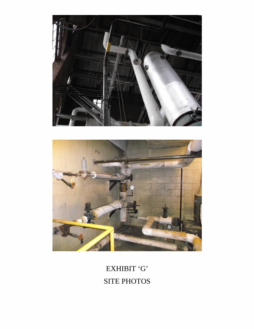
EXHIBIT ‘G’
SITE PHOTOS

EXHIBIT ‘G’
SITE PHOTOS