project no. a1143-00 state of new jersey sow/a1143-00 roof... · project no. a1143-00 state of new...
TRANSCRIPT
Document Format Revision (10/19/11)
SCOPE OF WORK
Roof Replacement
William F. Ashby Building Trenton, Mercer County, N.J.
PROJECT NO. A1143-00
STATE OF NEW JERSEY
Honorable Chris Christie, Governor Honorable Kim Guadagno, Lt. Governor
DEPARTMENT OF THE TREASURY
Andrew P. Sidamon-Eristoff, Treasurer
DIVISION OF PROPERTY MANAGEMENT AND CONSTRUCTION
Steven Sutkin, Director
Date: March 20, 2012

PROJECT NAME: Roof Replacement PROJECT LOCATION: William F. Ashby Building PROJECT NO: A1143-00 DATE: March 20, 2012
PAGE 2
TABLE OF CONTENTS SECTION PAGE
I. OBJECTIVE .......................................................................................... 6
II. CONSULTANT QUALIFICATIONS ................................................ 6
A. CONSULTANT & SUB-CONSULTANT PRE-QUALIFICATIONS .......................................... 6
III. PROJECT BUDGET ............................................................................ 6
A. CONSTRUCTION COST ESTIMATE (CCE) .............................................................................. 6 B. CURRENT WORKING ESTIMATE (CWE) ................................................................................ 6 C. COST ESTIMATING ..................................................................................................................... 7 D. CONSULTANT’S FEES ................................................................................................................ 7
IV. PROJECT SCHEDULE ....................................................................... 7
A. SCOPE OF WORK DESIGN & CONSTRUCTION SCHEDULE ............................................... 7 B. CONSULTANT’S PROPOSED DESIGN & CONSTRUCTION SCHEDULE ........................... 8 C. CONSULTANT DESIGN SCHEDULE ........................................................................................ 8 D. BID DOCUMENT CONSTRUCTION SCHEDULE .................................................................... 9 E. CONTRACTOR CONSTRUCTION PROGRESS SCHEDULE .................................................. 9
V. PROJECT SITE LOCATION & TEAM MEMBERS .................... 10
A. PROJECT SITE ADDRESS ......................................................................................................... 10 B. PROJECT TEAM MEMBER DIRECTORY ............................................................................... 10
1. DPMC Representative: ............................................................................................................. 10 2. Client Agency Representative: ................................................................................................. 10
VI. PROJECT DEFINITION ................................................................... 11
A. BACKGROUND .......................................................................................................................... 11 B. FUNCTIONAL DESCRIPTION OF THE ROOFING SYSTEM ............................................... 11
VII. CONSULTANT DESIGN RESPONSIBILITIES ............................ 11
A. NEW ROOF DESIGN REQUIREMENTS .................................................................................. 11 B. WARRANTY & PERFORMANCE AGREEMENT ................................................................... 15 C. CONTRACTOR CERTIFICATION ............................................................................................ 15 D. SITE REQUIREMENTS .............................................................................................................. 15 E. SPECIAL CONSIDERATIONS ................................................................................................... 16 F. GENERAL DESIGN OVERVIEW .............................................................................................. 17
1. Design Detail: ........................................................................................................................... 17 2. Specification Format: ................................................................................................................ 18
PROJECT NAME: Roof Replacement PROJECT LOCATION: William F. Ashby Building PROJECT NO: A1143-00 DATE: March 20, 2012
PAGE 3
G. PROJECT COMMENCEMENT .................................................................................................. 18 1. Project Directory: ...................................................................................................................... 18 2. Site Access: ............................................................................................................................... 18 3. Project Coordination: ................................................................................................................ 19 4. Existing Documentation: .......................................................................................................... 19 5. Scope of Work: ......................................................................................................................... 19 6. Project Schedule: ...................................................................................................................... 19
H. BUILDING & SITE INFORMATION ......................................................................................... 19 1. Building Classification: ............................................................................................................ 20 2. Building Block & Lot Number: ................................................................................................ 20 3. Building Site Plan: .................................................................................................................... 20 4. Site Location Map: .................................................................................................................... 20
I. DESIGN MEETINGS & PRESENTATIONS.............................................................................. 20 1. Design Meetings: ...................................................................................................................... 20 2. Design Presentations: ................................................................................................................ 21
VIII. CONSULTANT CONSTRUCTION RESPONSIBILITIES .......... 21
A. GENERAL CONSTRUCTION ADMINISTRATION OVERVIEW .......................................... 21 B. PRE-BID MEETING .................................................................................................................... 21 C. BID OPENING ............................................................................................................................. 21 D. POST BID REVIEW MEETING, RECOMMENDATION FOR AWARD ................................ 22
1. Post Bid Review:....................................................................................................................... 22 2. Review Meeting: ....................................................................................................................... 22 3. Substitutions:............................................................................................................................. 22 4. Schedule: ................................................................................................................................... 23 5. Performance: ............................................................................................................................. 23 6. Superintendent: ......................................................................................................................... 23 7. Letter of Recommendation: ...................................................................................................... 23 8. Conformed Drawings: ............................................................................................................... 24
E. DIRECTOR’S HEARING ............................................................................................................ 24 F. CONSTRUCTION JOB MEETINGS, SCHEDULES, LOGS ..................................................... 24
1. Meetings:................................................................................................................................... 24 2. Schedules: ................................................................................................................................. 25 3. Submittal Log: .......................................................................................................................... 25
G. CONSTRUCTION SITE ADMINISTRATION SERVICES ....................................................... 25 H. SUB-CONSULTANT PARTICIPATION.................................................................................... 26 I. ROOF MONITOR ALLOWANCE AND RESPONSIBILITIES ................................................ 26 J. EMERGENCY REPAIRS ............................................................................................................ 28 K. DRAWINGS ................................................................................................................................. 28
1. Shop Drawings: ......................................................................................................................... 28 2. As-Built & Record Set Drawings: ............................................................................................ 28
L. CONSTRUCTION DEFICIENCY LIST ..................................................................................... 29 M. INSPECTIONS: SUBSTANTIAL & FINAL COMPLETION ................................................ 29
PROJECT NAME: Roof Replacement PROJECT LOCATION: William F. Ashby Building PROJECT NO: A1143-00 DATE: March 20, 2012
PAGE 4
N. CLOSE-OUT DOCUMENTS ...................................................................................................... 30 O. CLOSE-OUT ACTIVITY TIME .................................................................................................. 30 P. MANUALS AND ATTIC STOCK .............................................................................................. 30
1. Operation & Maintenance Manuals: ......................................................................................... 30 2. Attic Stock: ............................................................................................................................... 31
Q. CHANGE ORDERS ..................................................................................................................... 31 1. Consultant: ................................................................................................................................ 31 2. Contractor: ................................................................................................................................ 31 3. Recommendation for Award: .................................................................................................... 32 4. Code Review: ............................................................................................................................ 32 5. Cost Estimate: ........................................................................................................................... 32 6. Time Extension: ........................................................................................................................ 32 7. Submission: ............................................................................................................................... 33 8. Meetings:................................................................................................................................... 33 9. Consultant Fee: ......................................................................................................................... 33
IX. PERMITS & APPROVALS ............................................................... 33
A. REGULATORY AGENCY PERMITS ........................................................................................ 33 1. NJ Uniform Construction Code Permit: ................................................................................... 34 2. Other Regulatory Agency Permits, Certificates, and Approvals: ............................................. 34 3. Prior Approval Certification Letters: ........................................................................................ 34
B. STATE INSURANCE APPROVAL ............................................................................................ 35 C. PUBLIC EMPLOYEES OCCUPATIONAL SAFETY & HEALTH PROGRAM ...................... 35 D. PERMIT MEETINGS ................................................................................................................... 35 E. CONSTRUCTION TRAILER PERMITS .................................................................................... 36 F. SPECIAL INSPECTIONS ............................................................................................................ 36
1. Definition: ................................................................................................................................. 36 2. Responsibilities: ........................................................................................................................ 36 3. Special Inspections: .................................................................................................................. 36
X. GENERAL REQUIREMENTS ......................................................... 37
A. SCOPE CHANGES ...................................................................................................................... 37 B. ERRORS and omissions ............................................................................................................... 37 C. ENERGY INCENTIVE PROGRAM ........................................................................................... 37 D. AIR POLLUTION FROM ARCHITECTURAL COATINGS .................................................... 38
XI. ALLOWANCES .................................................................................. 38
A. PERMIT FEE ALLOWANCE ..................................................................................................... 38 1. Permits: ..................................................................................................................................... 38 2. Permit Costs: ............................................................................................................................. 38 3. Applications: ............................................................................................................................. 39 4. Consultant Fee: ......................................................................................................................... 39

PROJECT NAME: Roof Replacement PROJECT LOCATION: William F. Ashby Building PROJECT NO: A1143-00 DATE: March 20, 2012
PAGE 5
B. ROOF MONITOR ALLOWANCE .............................................................................................. 39
XII. SUBMITTAL REQUIREMENTS ..................................................... 39
A. CONTRACT DELIVERABLES .................................................................................................. 39 B. CATALOG CUTS ........................................................................................................................ 39 C. PROJECT DOCUMENT BOOKLET .......................................................................................... 40 D. DESIGN DOCUMENT CHANGES ............................................................................................ 40 E. SINGLE-PRIME CONTRACT .................................................................................................... 40
XIII. SOW SIGNATURE APPROVAL SHEET ....................................... 41
XIV. CONTRACT DELIVERABLES ....................................................... 42
XV. EXHIBITS ............................................................................................ 48
A. SAMPLE PROJECT SCHEDULE FORMAT B. ROOF INVESTIGATION REPORT WILLIAM F. ASHBY BUILDING

PROJECT NAME: Roof Replacement PROJECT LOCATION: William F. Ashby Building PROJECT NO: A1143-00 DATE: March 20, 2012
PAGE 6
I. OBJECTIVE
The objective of this project is to remove approximately 25,200 square feet of a single ply EPDM roofing system with ballast rock that is installed on the William F. Ashby Building and replace it with a new energy efficient roofing system.
II. CONSULTANT QUALIFICATIONS
A. CONSULTANT & SUB-CONSULTANT PRE-QUALIFICATIONS
The Consultant shall be a firm pre-qualified with the Division of Property Management & Construction (DPMC) in the P035 Roofing Consultant Discipline and have in-house capabilities or Sub-Consultants pre-qualified with DPMC in all other Engineering and Specialty Disciplines necessary to complete the project as described in this Scope of Work (SOW). The Consultant shall also have in-house capabilities or Sub-Consultant pre-qualified in P028 Roofing Inspection Discipline. See Section VIII, paragraph I for a description of the P028 Roof Inspection responsibilities.
III. PROJECT BUDGET
A. CONSTRUCTION COST ESTIMATE (CCE) The initial Construction Cost Estimate (CCE) for this project is $1,000,000. The Consultant shall review this Scope of Work and provide a narrative evaluation and analysis of the accuracy of the proposed project CCE in their technical proposal based on their professional experience and opinion.
B. CURRENT WORKING ESTIMATE (CWE) The Current Working Estimate (CWE) for this project is $1,434,000. The CWE includes the construction cost estimate and all consulting, permitting and administrative fees.
PROJECT NAME: Roof Replacement PROJECT LOCATION: William F. Ashby Building PROJECT NO: A1143-00 DATE: March 20, 2012
PAGE 7
The CWE is the Client Agency’s financial budget based on this project Scope of Work and shall not be exceeded during the design and construction phases of the project unless DPMC approves the change in Scope of Work through a Contract amendment.
C. COST ESTIMATING On projects with a CCE under $750,000, the estimate may be prepared by the Consultant’s in-house staff or their Sub-Consultant’s staff during each design phase of the project. However, if the CCE is $750,000 or larger, the Consultant or Sub-Consultant providing the estimate must be pre-qualified with DPMC in the P025 Estimating/Cost Analysis Specialty Discipline. All cost estimates shall be adjusted for regional location, site factors, construction phasing, premium time, building use group, location of work within the building, temporary swing space, security issues, and inflation factors based on the year in which the work is to be performed. All cost estimates must be submitted on a DPMC-38 Project Cost Analysis form at each design phase of the project with a detailed construction cost analysis in CSI format (2004 Edition) for all appropriate divisions and sub-divisions. The Project Manager will provide cost figures for those items which may be in addition to the CCE such as art inclusion, CM services, etc. and must be included as part of the CWE. This cost analysis must be submitted for all projects regardless of the Construction Cost Estimate amount.
D. CONSULTANT’S FEES The construction cost estimate for this project shall not be used as a basis for the Consultant’s design and construction administration fees. The Consultant’s fees shall be based on the information contained in this Scope of Work document and the observations made and/or the additional information received during the pre-proposal meeting.
IV. PROJECT SCHEDULE
A. SCOPE OF WORK DESIGN & CONSTRUCTION SCHEDULE The following schedule identifies the estimated design and construction phases for this project and the estimated durations. PROJECT PHASE ESTIMATED DURATION (Calendar Days) 1. Design Development Phase 50% (Minimum) 28
• Project Team & DPMC Plan/Code Unit Review & Comment 14
PROJECT NAME: Roof Replacement PROJECT LOCATION: William F. Ashby Building PROJECT NO: A1143-00 DATE: March 20, 2012
PAGE 8
2. Final Design Phase 100% 28 • Project Team & DPMC Plan/Code Unit Review & Approval 14
3. Permit Application Phase 7
• Issue Permit 4. Bid Phase 42 5. Award Phase 28 6. Construction Phase 60
B. CONSULTANT’S PROPOSED DESIGN & CONSTRUCTION SCHEDULE
The Consultant shall submit a project design and construction bar chart schedule with their technical proposal that is similar in format and detail to the schedule depicted in Exhibit ‘A’. The bar chart schedule developed by the Consultant shall reflect their recommended project phases, phase activities, activity durations. The Consultant shall estimate the duration of the project Close-Out Phase based on the anticipated time required to complete each deliverable identified in Section XIV of this document entitled “Contract Deliverables - Project Close-Out Phase” and include this information in the bar chart schedule submitted. A written narrative shall also be included with the technical proposal explaining the schedule submitted and the reasons why and how it can be completed in the time frame proposed by the Consultant. This schedule and narrative will be reviewed by the Consultant Selection Committee as part of the evaluation process and will be assigned a score commensurate with clarity and comprehensiveness of the submission.
C. CONSULTANT DESIGN SCHEDULE The Project Manager will issue the Consultant’s approved project schedule at the first design kickoff meeting. This schedule will be binding for the Consultant’s activities and will include the start and completion dates for each design activity. The Consultant and Project Team members shall use this schedule to ensure that all design milestone dates are being met for the project. The Consultant shall update the schedule to reflect performance periodically (minimally at each design phase) for the Project Team review and approval. Any recommendations for deviations from the approved design schedule must be explained in detail as to the causes for the deviation(s) and impact to the schedule.
PROJECT NAME: Roof Replacement PROJECT LOCATION: William F. Ashby Building PROJECT NO: A1143-00 DATE: March 20, 2012
PAGE 9
D. BID DOCUMENT CONSTRUCTION SCHEDULE
The Consultant shall include a construction schedule in Division 1 of the specification bid document. This schedule shall contain, at minimum, the major activities and their durations for each trade specified for the project. This schedule shall be in “bar chart” format and will be used by the Contractors as an aid in determining their bid price. It shall reflect special sequencing or phased construction requirements including, but not limited to: special hours for building access, weather restrictions, imposed constraints caused by Client Agency program schedules, security needs, lead times for materials and equipment, anticipated delivery dates for critical items, utility interruption and shut-down constraints, and concurrent construction activities of other projects at the site and any other item identified by the Consultant during the design phases of the project.
E. CONTRACTOR CONSTRUCTION PROGRESS SCHEDULE The Contractor shall be responsible for preparing a coordinated combined progress schedule with the Sub-Contractors after the award of the contract. This schedule shall meet all of the requirements identified in the Consultant’s construction schedule. The construction schedule shall be completed in accordance with the latest edition of the Instructions to Bidders and General Conditions entitled, “Article 9, Construction Progress Schedule” (No CPM). The Consultant must review and analyze this progress schedule and recommend approval/disapproval to the Project Team until a satisfactory version is approved by the Project Team. The Project Team must approve the baseline schedule prior to the start of construction and prior to the Contractor submitting invoices for payment. The Consultant shall note in Division 1 of the specification that the State will not accept the progress schedule until it meets the project contract requirements and any delays to the start of the construction work will be against the Contractor until the date of acceptance by the State. The construction progress schedule shall be reviewed, approved, and updated by the Contractor of schedule, Consultant, and Project Team members at each regularly scheduled construction job meeting and the Consultant shall note the date and trade(s) responsible for project delays (as applicable).
PROJECT NAME: Roof Replacement PROJECT LOCATION: William F. Ashby Building PROJECT NO: A1143-00 DATE: March 20, 2012
PAGE 10
V. PROJECT SITE LOCATION & TEAM MEMBERS
A. PROJECT SITE ADDRESS The location of the project site is: William F. Ashby Building (DCA Building) 101 Broad Street Trenton, NJ 08625-0800 See Exhibit ‘B’ for the project site photos and location.
B. PROJECT TEAM MEMBER DIRECTORY The following are the names, addresses, and phone numbers of the Project Team members. 1. DPMC Representative: Name: Eugene Cardone, Project Manager Address: Division Property Management & Construction 20 West State Street, 3rd Floor Trenton, NJ 08625 Phone No: (609) 633-2648 E-Mail No: [email protected] 2. Client Agency Representative: Name: Gary Karr, Chief, Property Management Address: Division Property Management & Construction 20 West State Street, 3rd Floor Trenton, NJ 08625 Phone No: (609) 984-5933 E-Mail No: [email protected]
PROJECT NAME: Roof Replacement PROJECT LOCATION: William F. Ashby Building PROJECT NO: A1143-00 DATE: March 20, 2012
PAGE 11
VI. PROJECT DEFINITION
A. BACKGROUND In 2011, the State of New Jersey commissioned Ronald A. Sebring Associates (RASA) to conduct a physical conditions survey of the roofing system on the William F. Ashby Building which houses the Department of Community Affairs. The building has leaks in various locations. Nuclear gauge moisture testing was performed to locate areas of water infiltration. Areas of roof material delamination, cuts and other defects were noted. A Roof Investigation Report was produced with photos, recommendations and cost estimates for the repair of the roofing system. See Exhibit ‘B’ for the report. Ultimately, RASA recommended replacing the entire roofing system with a built-up bituminous roofing system. This project will implement that recommendation.
B. FUNCTIONAL DESCRIPTION OF THE ROOFING SYSTEM The existing 25,200 square feet roofing system is a single ply, loose laid, EPDM membrane with river rock ballast over tapered rigid insulation. This sits on 1 ½ “ metal decking. There is spray-applied fire proofing on the underside of the deck and structural roof framing. HVAC units sitting on solid curbs occupy about 1,280 square feet of the roof. Parapet walls of varying heights surround the perimeter of the roof. A further description can be found in the Roof Investigation Report shown in Exhibit ‘B’.
VII.CONSULTANT DESIGN RESPONSIBILITIES
A. NEW ROOF DESIGN REQUIREMENTS 1. Roof System Removal: The existing roof system, insulation, flashings, and related trims on the William F. Ashby Building shall be completely removed to the original decking and legally disposed. The removal of the existing roof system shall be coordinated with the installation of the new roof to prevent exposure to weather conditions and potential water infiltration into the building. Design documents shall identify all requirements for safety devices, dumpster location, chutes or other methods of roofing material removal, protection from exposure to the weather, protection
PROJECT NAME: Roof Replacement PROJECT LOCATION: William F. Ashby Building PROJECT NO: A1143-00 DATE: March 20, 2012
PAGE 12
of property and personnel, building access routes and circulation patterns, contractor use of the premises, parking, security procedures, equipment and materials storage, waste disposal, etc. 2. Caulking & Joint Sealants: All appropriate roof deck joint sealants shall be removed and replaced with high performance sealant as part of the roof system. The design shall include the cleaning, priming, and installation of new sealants with new backer rods and bond breakers. Examine and measure all exterior joints and calculate the required joint width(s). Design for widening joints as required. Observe the installation of the sealant joints, performing pull tests for cohesion and adhesion on a random sampling of each joint type. Specify that the sealant manufacturer must provide a warranty for a minimum of twenty (20) years for any repairs to maintain joints in a leak free condition and at no cost to the State. 3. Insulation: Recommend new high-density rigid insulation boards that comply with current energy code requirements. Ensure the roofing system manufacturer approves the method of fastening the insulation board to the roof deck system. Flat roofs shall be avoided by using tapered insulation to promote positive drainage to the roof drains. Incorporate a roof design that shall slope a minimum of ¼” per foot (½” per foot preferred). DPMC does not permit Urethane material insulation due to a history of gas release and bubbling under the roofing ply layer(s). 4. New Roofing System Criteria: Provide the design and specifications for a built-up bituminous roofing system for the William F. Ashby Building in accordance with the requirements of the roofing manufacturer and those described in the DPMC Procedures for Architects and Engineers Manual. The manufacturer of the roofing system shall have no less than five (5) years successful experience in producing the materials required for this project. Membrane, flashing, and adhesive shall be the single product of a standard manufacturer. The roofing system shall be in accordance with the latest ASHRAE 90.1 (latest version) energy standards.
PROJECT NAME: Roof Replacement PROJECT LOCATION: William F. Ashby Building PROJECT NO: A1143-00 DATE: March 20, 2012
PAGE 13
The roofing system shall be in compliance with the “Factory Mutual Research Corp” (FMRC) standards and must meet all requirements of Factory Mutual I-90 classification for wind uplift. The Contractor shall supply only a U.L. Class “A” fire rated roofing system. Since the roofing system and/or related components are not a replacement in kind, the Consultant shall submit signed and sealed calculations to the DPMC Design and Code Review Unit Manager verifying that the existing roof structure can support all loads of the new roofing system and components per current code requirements. 5. Flashing: All rooftop HVAC curbing, parapet walls, conduit, pipe supports, pipe vents, roof hatch, ventilation fans, and other roof penetrations must have new flashing installed as part of this project. All pipe flashings are to be pre-molded and provided with stainless steel pipe clamps at each penetration. 6. Parapet Walls & Coping: Provide a design to repair or replace any damaged coping on the parapet walls as part of this project including design details to seal the coping joints. 7. Building Component Repairs: Provide a design to repair the damaged lightning protection cable as identified in the Roof Inspection Report. The contract documents shall indicate the scope and methods of the proposed repairs and replacements to allow for permitting, bidding and construction purposes. The design documents shall be accurate and include sufficient detail to cover all conditions for fixed price quotations of the work. 8. Removals: Remove all unused towers, antennas, conduit, piping, structural steel support systems, curbing, etc. Details shall be included on the drawings that indicate the methods to seal all roof penetrations and cap all piping below the new roof line as appropriate. 9. Walkways: Provide new walkway protection from access points to and around all roof mounted HVAC units and/or other similar equipment requiring periodic servicing and any other trafficking areas. If
PROJECT NAME: Roof Replacement PROJECT LOCATION: William F. Ashby Building PROJECT NO: A1143-00 DATE: March 20, 2012
PAGE 14
existing walk pads are to be reused then verify that they are compatible with the new roofing system. 10. Roof Drains: All drains shall be removed and reset or repositioned so that the drain is below the roof membrane surface. Provide for the interior cleaning, repair, replacement and additional drains as required and ensure that drainage water will be carried away from the building foundations, footings, lanes, sidewalks and driveways. Investigate the abandonment of leaking interior drain lines and the installation of new interior lines where access is impossible for repairs and/or replacement. Provide additional roof drains where required to eliminate standing or ponding water. New interior roof drain piping shall be designed to avoid interference with existing ductwork, structural members, and miscellaneous piping, electrical conduit, hangers, etc. The design documents shall include detailed information that describes the methods required to protect the furniture, equipment, and interior building finishes. 11. Night Seals: Specify in the design documents that only as much roofing insulation, membrane, and flashing as can be made weather tight shall be installed each day. Install temporary water tight night seals around all exposed edges of the roofing assembly at the end of each work day and when work must be postponed due to inclement weather. 12. Fire Protection Program: Address fire protection requirements during the demolition and installation of the roofing system. Language shall be included that states open flames such as propane torches, kettles, flame cutting, and welding cannot be used on the construction site until a fire watch program has been submitted by the Contractor and approved by the Consultant and Project Team members. 13. Allowable Roof System Installation: The design documents shall specify the weather and temperature installation restrictions based on the roof system manufacturer’s recommendations. 14. Unit Prices: If the total amount or quantity of repair work cannot be determined for a roof related item, then the Consultant shall include a “Unit Price” Section in Division 1 of the specification for that item. Items may include deteriorated decking, plywood sheathing, wood blocking or curbing, vapor barriers, interior roof drains, etc.
PROJECT NAME: Roof Replacement PROJECT LOCATION: William F. Ashby Building PROJECT NO: A1143-00 DATE: March 20, 2012
PAGE 15
B. WARRANTY & PERFORMANCE AGREEMENT
1. Warranty: The roofing manufacturer’s warranty shall be for a period of twenty (20) years. 2. Performance Agreement: The Contractor shall provide a five (5) year performance agreement on labor and material in addition to the manufacturer’s warranty. This performance shall include an annual inspection and written report on a DPMC Inspection Form, for each of the five (5) years. The performance agreement shall include the stipulation that the Contractor shall perform all inspections and emergency repairs to all defects or leaks in the roofing system within four (4) hours of receipt of notice from the owner. Repairs shall include all labor, roofing materials, flashings, etc. When weather permits, all temporary repairs shall be redone and the roof restored to the standard of the original installation.
C. CONTRACTOR CERTIFICATION The Consultant shall state in the design documents that the DPMC Contractor Classification Group must have certification in writing from the roofing system manufacturer that the Roofing Contractor is a licensed or approved installer of the roofing system selected for the project.
D. SITE REQUIREMENTS 1. Contractor Use of the Premises: Determine the coordination, policies, and procedures with the Client Agency and the Contractor with respect to parking, material staging, and storage areas, use of Client Agency utilities, allowable hours of construction, the need and location of portable toilets, the need and location of construction and storage trailers, etc. and include the information in Division 1 of the specification. 2. Dumpster: The location and security requirements of the dumpster shall be identified on the site plan in an area approved by the Client Agency, and the frequency of debris removal shall be identified in the design specification. 3. Special Sequencing:

PROJECT NAME: Roof Replacement PROJECT LOCATION: William F. Ashby Building PROJECT NO: A1143-00 DATE: March 20, 2012
PAGE 16
The contract documents must incorporate special sequencing of the work, if necessary, to be coordinated with the Client Agency in order to provide for any functional requirement of the facility. Items shall include, but not be limited to: safety/security requirements, pedestrian and vehicle traffic flow, weather and/or seasonal concerns, and shut down of any physical plant functions or services. 4. Site Restoration: Include in the contract documents that the site must be restored to pre-construction conditions after construction has been completed and approved.
E. SPECIAL CONSIDERATIONS 1. Security: Include any special security requirements or policies published by the Client Agency in Division 1 of the specification. 2. Hours of Work: Identify the approved construction work hours for this project in Division 1 of the specification. Special hours required to install any internal roof drains in the building shall be identified if required. Additional construction hours during the day or weekends will be allowed if the Contractor obtains prior approval from the Project Team members. 3. Trailers: Provide a storage trailer and meeting room at the construction site if required for the project and in an area approved by the Client Agency. 4. Material Staging: The Client Agency shall approve the construction material staging area and the location shall be shown on the project site plan. 5. Material Protection: All stored roofing felts, insulation boards, and/or other roofing components shall be protected from the elements and moisture with plastic sheet covers or other approved materials. 6. Material Safety Data Sheets (MSDS):
PROJECT NAME: Roof Replacement PROJECT LOCATION: William F. Ashby Building PROJECT NO: A1143-00 DATE: March 20, 2012
PAGE 17
Specify in the contract documents that the Contractor shall provide material safety data sheets on site for all roofing materials used such as: sealants, bonding adhesives, solvents, bitumen, etc. 7. Fire Extinguishers: Design documents shall require the Contractor to make provisions for stand-by portable fire extinguishers of proper size and type. They shall be located on the roof and/or near any source of open flame or spark and all employees shall be trained in their proper use. 8. HVAC Unit, Roof Ventilators, Intake Fans: Requirements to shutdown all rooftop equipment and allowable hours of adhesive application shall be identified in the contract documents to prevent fumes from entering the building. 9. Roof Antenna: Indicate if the Contractor or Client Agency will remove and replace any existing roof antennas and mounting fixtures in the contract documents. 10. Vapor Recovery Equipment: Vapor recovery systems shall be used in conjunction with the asphalt adhesive application. The kettle shall be located considering wind direction, open windows, HVAC air intake louver locations, adjacent buildings, etc. The allowable hours of adhesive application shall be identified in the contract documents and if the building may be occupied during the application. 11. Existing Equipment Removal & Replacement: Identify on the design drawings any existing equipment and materials that must be removed in order to install any component of the new roofing system such as: lights, security cameras, lightning protection systems, antennas, piping, conduit, etc. and include details indicating the approved methods of reattachment.
F. GENERAL DESIGN OVERVIEW
1. Design Detail: Section VII of this Scope of Work is intended as a guide for the Consultant to understand the overall basic design requirements of the project and is not intended to identify each specific design component related to code and construction items. The Consultant shall provide those details during the design phase of the project ensuring that they are in compliance with all applicable codes, regulating authorities, and the guidelines established in the DPMC Procedures for Architects and Engineers Manual.

PROJECT NAME: Roof Replacement PROJECT LOCATION: William F. Ashby Building PROJECT NO: A1143-00 DATE: March 20, 2012
PAGE 18
The Consultant shall understand that construction documents submitted to DPMC shall go beyond the basic requirements set forth by the current copy of the Uniform Construction Code NJAC 5:23-2.15(f). Drawings and specifications shall provide detail beyond that required to merely show the nature and character of the work to be performed. The construction documents shall provide sufficient information and detail to illustrate, describe and clearly delineate the design intent of the Consultant and enable all Contractors to uniformly bid the project. The Consultant shall ensure that all of the design items described in this scope of work are addressed and included in the project drawings and specification sections where appropriate. It shall be the Consultant’s responsibility to provide all of the design elements for this project. Under no circumstance may they delegate the responsibility of the design; or portions thereof, to the Contractor unless specifically allowed in this Scope of Work. 2. Specification Format: The Consultant shall ensure that the project design specifications are formatted in the revised and expanded version of the Construction Specifications Institute (CSI) format entitled “Master Format 2004 Edition: Numbers and Titles.” The Consultant shall review all of the CSI Master Format 2004 specification sections listed and remove those that do not apply and edit those that remain so they are consistent and specific to this project scope of work.
G. PROJECT COMMENCEMENT A pre-design meeting shall be scheduled with the Consultant and the Project Team members at the commencement of the project to obtain and/or coordinate the following information: 1. Project Directory: Develop a project directory that identifies the name and phone number of key designated representatives who may be contacted during the design and construction phases of this project. 2. Site Access: Develop procedures to access the project site and provide the names and phone numbers of approved escorts when needed. Obtain copies of special security and policy procedures that must be followed during all work conducted at the facility and include this information in Division 1 of the specification.
PROJECT NAME: Roof Replacement PROJECT LOCATION: William F. Ashby Building PROJECT NO: A1143-00 DATE: March 20, 2012
PAGE 19
3. Project Coordination: Review and become familiar with any current and/or future projects at the site that may impact the design, construction, and scheduling requirements of this project. Incorporate all appropriate information and coordination requirements in Division 1 of the specification. 4. Existing Documentation: Review any documents and additional information that may be provided at a later date such as reports, studies, surveys, equipment manuals, as-built drawings, etc. The State does not attest to the accuracy of the information provided and accepts no responsibility for the consequences of errors by the use of any information and material contained in the documentation provided. It shall be the responsibility of the Consultant to verify the contents and assume full responsibility for any determination or conclusion drawn from the material used. If the information provided is insufficient, the Consultant shall take the appropriate actions necessary to obtain the additional information required. All original documentation shall be returned to the provider at the completion of the project. 5. Scope of Work: Review the design and construction administration responsibilities and the submission requirements identified in this Scope of Work with the Project Team members. Items such as: contract deliverables, special sequencing or phased construction requirements, special hours for construction based on Client Agency programs or building occupancy, security needs, delivery dates of critical and long lead items, utility interruptions or shut down constraints for tie-ins, weather restrictions, and coordination with other project construction activities at the site shall be addressed. This information and all general administrative information; including a narrative summary of the work for this project, shall be included in Division 1 of the specification. The Consultant shall assure that there are no conflicts between the information contained in Division 1 of the specification and the DPMC General Conditions. 6. Project Schedule: Review and update the project design and construction schedule with the Project Team members.
H. BUILDING & SITE INFORMATION The following information shall be included in the project design documents.
PROJECT NAME: Roof Replacement PROJECT LOCATION: William F. Ashby Building PROJECT NO: A1143-00 DATE: March 20, 2012
PAGE 20
1. Building Classification: Provide the building Use Group Classification and Construction Type on the appropriate design drawing. 2. Building Block & Lot Number: Provide the site Block and Lot Number on the appropriate design drawing. 3. Building Site Plan: Only when the project scope involves site work, or when the design triggers code issues that require site information to show code compliance, shall a site plan be provided that is drawn in accordance with an accurate boundary line survey. The site plan shall include, but not be limited to, the following as may be applicable: • The size and location of new and existing buildings and additions as well as other structures. • The distance between buildings and structures and to lot lines. • Established and new site grades and contours as well as building finished floor elevations. • New and existing site utilities, site vehicular and pedestrian roads, walkways and parking
areas. 4. Site Location Map: Provide a site location map on the drawing cover sheet that identifies the vehicular travel routes from major roadways to the project construction site and the approved access roads to the Contractor’s worksite staging area.
I. DESIGN MEETINGS & PRESENTATIONS 1. Design Meetings: Conduct the appropriate number of review meetings with the Project Team members during each design phase of the project so they may determine if the project meets their requirements, question any aspect of the contract deliverables, and make changes where appropriate. The Consultant shall describe the philosophy and process used in the development of the design criteria and the various alternatives considered to meet the project objectives. Selected studies, sketches, cost estimates, schedules, and other relevant information shall be presented to support the design solutions proposed. Special considerations shall also be addressed such as: Contractor site access limitations, utility shutdowns and switchover coordination, phased construction and schedule requirements, security restrictions, available swing space, material and equipment delivery dates, etc.
PROJECT NAME: Roof Replacement PROJECT LOCATION: William F. Ashby Building PROJECT NO: A1143-00 DATE: March 20, 2012
PAGE 21
It shall also be the responsibility of the Consultant to arrange and require all critical Sub-Consultants to be in attendance at the design review meetings. Record the minutes of each design meeting and distribute within seven (7) calendar days to all attendees and those persons specified to be on the distribution list by the Project Manager. 2. Design Presentations: The minimum number of design presentations required for each phase of this project is identified below for reference: Design Development Phase: One (1) oral presentation at phase completion. Final Design Phase: One (1) oral presentation at phase completion.
VIII.CONSULTANT CONSTRUCTION RESPONSIBILITIES
A. GENERAL CONSTRUCTION ADMINISTRATION OVERVIEW This section of the Scope of Work is intended as a guide for the Consultant to understand their overall basic construction administration responsibilities for the project and does not attempt to identify each specific activity or deliverable required during this phase. The Consultant shall obtain that information from the current publication of the DPMC Procedures for Architects and Engineers Manual and any additional information provided during the Consultant Selection Process.
B. PRE-BID MEETING The Consultant shall attend, chair, record and distribute minutes of the Contractor pre-bid meetings. When bidders ask questions that may affect the bid price of the project, the Consultant shall develop a Bulletin(s) to clarify the bid documents in the format described in the Procedures for Architects and Engineers Manual, Section 9.2 entitled “Bulletins.” These Bulletins must be sent to DPMC at least seven (7) calendar days prior to the bid opening date. DPMC will then distribute the document to all bidders.
C. BID OPENING The Consultant must attend the bid opening held at the designated location.
PROJECT NAME: Roof Replacement PROJECT LOCATION: William F. Ashby Building PROJECT NO: A1143-00 DATE: March 20, 2012
PAGE 22
In the event that the construction bids received exceed the Consultant’s approved final cost estimate by 5% or more, the Consultant shall redesign and/or set up sufficient approved alternate designs, plans and specifications for the project work, to secure a bid that will come within the allocation specified by the State without impacting the programmatic requirements of the project. Such redesign work and changes to plans, including reproduction costs for submission in order to obtain final approval and permits, shall be undertaken by the Consultant at no additional cost to the State.
D. POST BID REVIEW MEETING, RECOMMENDATION FOR AWARD The Consultant; in conjunction with the Project Manager, shall review the bid proposals submitted by the various Contractors to determine the low responsible bid for the project. The Consultant; in conjunction with the Project Manager, shall develop a post bid questionnaire based on the requirements below and schedule a post bid review meeting with the Contractor’s representative to review the construction costs and schedule, staffing, and other pertinent information to ensure they understand the Scope of the Work and that their bid proposal is complete and inclusive of all requirements necessary to deliver the project in strict accordance with the plans and specifications. 1. Post Bid Review: Review the project bid proposals including the alternates, unit prices, and allowances within seven (7) calendar days from the bid due date. Provide a bid tabulation matrix comparing all bids submitted and make a statement about the high, low, and average bids received. Include a comparison of the submitted bids to the approved current construction cost estimate. When applicable, provide an analysis with supporting data, detailing why the bids did not meet the construction cost estimate. 2. Review Meeting: Arrange a meeting with the apparent low bid Contractor to discuss their bid proposal and other issues regarding the award of the contract. Remind the Contractor that this is a Lump Sum bid. Request the Contractor to confirm that their bid proposal does not contain errors. Review and confirm Alternate pricing and Unit pricing and document acceptance or rejection as appropriate. Comment on all omissions, qualifications and unsolicited statements appearing in the proposals. Review any special circumstances of the project. Ensure the Contractor’s signature appears on all post bid review documents. 3. Substitutions: Inquire about any potential substitutions being contemplated by the Contractor and advise them of the State’s guidelines for the approval of substitutions and the documentation required.
PROJECT NAME: Roof Replacement PROJECT LOCATION: William F. Ashby Building PROJECT NO: A1143-00 DATE: March 20, 2012
PAGE 23
Review the deadline and advise the Contractor that partial submissions are not acceptable. Submission after the deadline may be rejected by the State. Equal substitutions that are proposed by the Contractor that are of lesser value must have a credit change order attached with the submittal (See Article 4 of the General Conditions). The State has the right to reject the submission if there is no agreement on the proposed credit. Contractor will be responsible to submit a specified item. 4. Schedule: Confirm that the Contractor is aware of the number of calendar days listed in the contract documents for the project duration and that the Contractor’s bid includes compliance with the schedule duration and completion dates. Particular attention shall be given to special working conditions, long lead items and projected delivery dates, etc. Review project milestones (if applicable). This could give an indication of Contractor performance, but not allow a rejection of the bid. Review the submittal timeframes per the Contract documents. Ask the Contractor to identify what products will take over twenty-eight (28) calendar days to deliver from the point of submittal approval. 5. Performance: Investigate the past performance of Contractor by contacting Architects and owners (generally three of each) that were listed in their DPMC pre-qualification package and other references that may have been provided. Inquire how the Contractor performed with workmanship, schedule, project management, change orders, cooperation, paper work, etc. 6. Superintendent: Remind the Contractor that a full-time non-working superintendent is required per the General Conditions, who must be responsible to address Contract issues. (Article 4.3.2.). 7. Letter of Recommendation: The Consultant shall prepare a Letter of Recommendation for contract award to the Contractor submitting the low responsible bid within three (3) calendar days from the post bid review meeting. The document shall contain the project title, DPMC project number, bid due date and expiration date of the proposal. It shall include a detailed narrative describing each post bid meeting agenda item identified above and a recommendation to award the contract to the apparent low bid Contractor based on the information obtained during that meeting. Describe any acceptance or rejection of Alternate pricing and Unit pricing.
PROJECT NAME: Roof Replacement PROJECT LOCATION: William F. Ashby Building PROJECT NO: A1143-00 DATE: March 20, 2012
PAGE 24
Comment on any discussion with the Contractor that provides a sense of their understanding of the project and any special difficulties that they see, and how they might approach those problems. Attach all minutes of the Post bid meeting and any other relevant correspondence with the Letter of Recommendation and submit them to the Project Manager. 8. Conformed Drawings: The Consultant shall prepare and distribute two (2) sets of drawings stamped “Conformed Drawings” to the Project Manager that reflect all Bulletins and/or required changes, additions, and deletions to the pertinent drawings within fourteen (14) calendar days of the construction contract award date. Any changes made in Bulletins, meeting minutes, post bid review requirements shall also be reflected in the specification.
E. DIRECTOR’S HEARING
The Consultant must attend any Director’s hearing(s) if a Contractor submits a bid protest. The Consultant shall be present to interpret the intent of the design documents and answer any technical questions that may result from the meeting. In cases where the bid protest is upheld, the Consultant shall submit a new “Letter of Recommendation” for contract award. The hours required to attend the potential hearings and to document the findings shall be estimated by the Consultant and the costs will be included in the base bid of their fee proposal.
F. CONSTRUCTION JOB MEETINGS, SCHEDULES, LOGS The Consultant shall conduct all of the construction job meetings, to be held bi-weekly for the duration of construction, in accordance with the procedures identified in the A/E manual and those listed below. 1. Meetings: The Consultant and Sub-Consultant(s) shall attend the pre-construction meeting and all construction job meetings during the construction phase of the project. The Consultant shall chair the meeting, transcribe and distribute the job-meeting minutes for every job meeting to all attendees and to those persons specified to be on the distribution list by the Project Manager. The Agenda for the meeting shall include, but not be limited to the items identified in the Procedures for Architects and Engineers Manual, Section 10.3.1, entitled “Agenda.” Also, the Consultant is responsible for the preparation and distribution of minutes within three (3) calendar days of the meeting. The format to be used for the minutes shall comply with those
PROJECT NAME: Roof Replacement PROJECT LOCATION: William F. Ashby Building PROJECT NO: A1143-00 DATE: March 20, 2012
PAGE 25
identified in the “Procedures for Architects and Engineers Manual,” Section 10.3.4, entitled, “Format of Minutes.” All meeting minutes are to have an “action” column indicating the party that is responsible for the action indicated and a deadline to accomplish the assigned task. These tasks must be reviewed at each job progress meeting until it is completed and the completion date of each task shall be noted in the minutes of the meeting following the task completion. 2. Schedules: The Consultant; with the input from the Client Agency Representative and Project Manager, shall review and recommend approval of the project construction schedule prepared by the Contractor. The schedule shall identify all necessary start and completion dates of construction, construction activities, submittal process activities, material deliveries and other milestones required to give a complete review of the project. The Consultant shall record any schedule delays, the party responsible for the delay, the schedule activity affected, and the original and new date for reference. The Consultant shall ensure that the Contractor provides a two (2) week “look ahead” construction schedule based upon the current monthly updated schedule as approved at the bi-weekly job meetings and that identifies the daily planned activities for that period. This Contractor requirement must also be included in Division 1 of the specification for reference. 3. Submittal Log: The Consultant shall develop and implement a submittal log that will identify all of the required project submittals as identified in the design specification. The dates of submission shall be determined and approved by all affected parties during the pre-construction meeting. Examples of the submissions to be reviewed and approved by the Consultant and Sub-Consultant (if required) include: shop drawings, change orders, Request for Information (RFI), equipment and material catalog cuts, spec sheets, product data sheets, MSDS material safety data sheets, specification procedures, color charts, material samples, mock-ups, etc. The submittal review process must be conducted at each job progress meeting and shall include the Consultant, Sub-Consultant, Contractor, Project Manager, and designated representatives of the Client Agency. The Consultant shall provide an updated submittal log at each job meeting that highlights all of the required submissions that are behind schedule during the construction phase of the project.
G. CONSTRUCTION SITE ADMINISTRATION SERVICES The Consultant and Sub-Consultant(s) shall provide construction site administration services during the duration of the project. The Consultant and Sub-Consultant(s) do not necessarily have

PROJECT NAME: Roof Replacement PROJECT LOCATION: William F. Ashby Building PROJECT NO: A1143-00 DATE: March 20, 2012
PAGE 26
to be on site concurrently if there are no critical activities taking place that require the Sub-Consultant’s participation. The services required shall include, but not be limited to; field observations sufficient to verify the quality and progress of construction work, conformance and compliance with the contract documents, and to attend/chair meetings as may be required by the Project Manager to resolve special issues. Consultant and Sub-Consultant(s) shall conduct weekly site inspection/field observation visits. Site inspection/field observation visits may be conducted in conjunction with regularly scheduled bi-weekly construction job meetings, depending on the progress of work, for weeks that construction job meetings are scheduled. The Consultant and their Sub-Consultant(s) shall submit a field observation report for each site inspection to the Project Manager. Also, they shall conduct inspections during major construction activities including, but not limited to the following examples: concrete pours, steel and truss installations, code inspections, final testing of systems, achievement of each major milestone required on the construction schedule, and requests from the Project Manager. The assignment of a full time on-site Sub-Consultant does not relieve the Consultant of their site visit obligation. The Consultant shall refer to Section XIV. Contract Deliverables of this Scope of Work subsection entitled “Construction Phase” to determine the extent of services and deliverables required during this phase of the project.
H. SUB-CONSULTANT PARTICIPATION It is the responsibility of the Consultant to ensure that they have provided adequate hours and/or time allotted in their technical proposal so that their Sub-Consultants may participate in all appropriate phases and activities of this project or whenever requested by the Project Manager. This includes the pre-proposal site visit and the various design meetings and construction job meetings, site visits, and close-out activities described in this Scope of Work. Field observation reports and/or meeting minutes are required to be submitted to the Project Manager within three (3) calendar days of the site visit or meeting. All costs associated with such services shall be included in the base bid of the Consultant’s fee proposal.
I. ROOF MONITOR ALLOWANCE AND RESPONSIBILITIES 1. Roof Monitor Allowance: The Consultant shall estimate the costs associated with providing a full time roof monitor during the installation of the roof system on the building and enter that amount in their fee proposal line item entitled “Roof Monitor Allowance”.
PROJECT NAME: Roof Replacement PROJECT LOCATION: William F. Ashby Building PROJECT NO: A1143-00 DATE: March 20, 2012
PAGE 27
A detailed cost breakdown sheet shall be attached to the fee proposal that identifies the amounts proposed for the various activities associated with the allowance and may be used by DPMC during the proposal review and potential fee negotiations. Any funds remaining in the allowance shall be returned to the State at the end of the project. The responsibilities of the roof monitor shall include, but not be limited to the following items: 2. Roof Monitor Inspections: The Consultant shall have in-house capabilities or a Sub-Consultant pre-qualified with DPMC in the P028 Roofing Inspection Specialty Discipline. If a Sub-Consultant is required, the costs for the services provided shall be borne by the Consultant and included in the base bid of their fee proposal. A cost breakdown sheet shall accompany the fee proposal that identifies all costs associated with the Roof Monitoring services to be provided. The Roof Monitor must continuously inspect and monitor the Contractor’s work on site and file a daily DPMC 605 Roofing Inspector’s Check List Form to ensure compliance with the contract documents. Photographs shall be included for reference. The report shall include weather conditions, number of workers, and the amount of roof removed and installed together with comments on each phase of work. Comments shall provide descriptions and information on project mobilization, material delivery, removal of existing roof system, preparation of the existing deck, installation of the new underlayment and/or insulation, sealant and adhesive applications, flashing, walkways, etc. 3. Inclement Weather: The Consultant, in conjunction with the Roof Monitor, shall anticipate time losses due to seasonal inclement weather conditions such as rain, wind and low ambient temperatures and include these hours in the base bid of the fee proposal. On the first day of inclement weather, the Roof Monitor will be entitled to four hours to visit the site and inspect the roofing system for potential roof leaks or damage. Additional time spent on the site during inclement weather will not be reimbursed unless directed by the Project Manager. 4. Unsatisfactory Work: If the Roof Monitor determines that the roof Contractor is installing the roofing system improperly, he shall notify the Contractor to stop all work until the Consultant is notified and inspects the work for design conformity. If appropriate, provisions shall be made to seal the roof work area until the Consultant arrives and the installation issues are resolved. If the Consultant determines that the installation does not meet the intentions of the design or indicates poor workmanship, he shall notify the Project Manager that he recommends the
PROJECT NAME: Roof Replacement PROJECT LOCATION: William F. Ashby Building PROJECT NO: A1143-00 DATE: March 20, 2012
PAGE 28
questionable roofing installation be removed and replaced properly. The Project Manager shall then notify the Contractor verbally to take the recommended action and shall follow up with a written directive indicating the time and date the Contractor was notified. 5. Meetings: The Consultant and Roof Monitor shall both attend the pre-construction conference and all periodic job progress meetings during the construction phase of the project.
J. EMERGENCY REPAIRS The Consultant must include information in the contract documents that will address the Contractor’s responsibility for repairs to the roofing system during the construction phase of the project. The information shall include, but not be limited to the following: 1. Repair Period: Stipulate in the contract documents that the Contractor shall perform all inspections and emergency repairs to all defects or leaks in the roofing system during construction within four (4) hours of receipt of notice from the owner. Repairs shall include all labor, roofing materials, flashing, etc. When weather permits, all temporary repairs shall be redone and the roof restored to the standard of the original installation.
K. DRAWINGS 1. Shop Drawings: Each Contractor shall review the specifications and determine the numbers and nature of each shop drawing submittal. Five (5) sets of the documents shall be submitted with reference made to the appropriate section of the specification. The Consultant shall review the Contractor’s shop drawing submissions for conformity with the construction documents within seven (7) calendar days of receipt. The Consultant shall return each shop drawing submittal stamped with the appropriate action, i.e. “Approved”, “Approved as Noted”, “Approved as Noted Resubmit for Records”, “Rejected”, etc. 2. As-Built & Record Set Drawings: The Contractor(s) shall keep the contract drawings up-to-date at all times during construction and upon completion of the project, submit their AS-BUILT drawings to the Consultant with the Contractor(s) certification as to the accuracy of the information prior to final payment. All AS-BUILT drawings submitted shall be entitled AS-BUILT above the title block and dated.
PROJECT NAME: Roof Replacement PROJECT LOCATION: William F. Ashby Building PROJECT NO: A1143-00 DATE: March 20, 2012
PAGE 29
The Consultant shall review the Contractor(s)’ AS-BUILT drawings at each job progress meeting to ensure that they are up-to-date. Any deficiencies shall be noted in the progress meeting minutes. The Consultant shall acknowledge acceptance of the AS-BUILT drawings by signing a transmittal indicating they have reviewed them and that they reflect the AS-BUILT conditions as they exist. Upon receipt of the AS-BUILT drawings from the Contractor(s), The Consultant shall obtain the original mylars from DPMC and transfer the AS-BUILT conditions to the original full sized signed mylars to reflect RECORD conditions within fourteen (14) calendar days of receipt of the AS-BUILT information. The Consultant shall note the following statement on the original RECORD-SET drawings. “The AS-BUILT information added to this drawing(s) has been supplied by the Contractor(s). The (Architect) (Engineer) does not assume the responsibility for its accuracy other than conformity with the design concept and general adequacy of the AS-BUILT information to the best of the (Architect’s) (Engineer’s) knowledge.” Upon completion, The Consultant shall deliver the RECORD-SET original mylars to DPMC who will acknowledge their receipt in writing. This hard copy set of drawings and three (3) sets of current release AUTO CAD discs shall be submitted to DPMC and the discs shall contain all AS-BUILT drawings in both “.dwg” (native file format for AUTO CAD) and “.tif” (Tagged Image File) file formats.
L. CONSTRUCTION DEFICIENCY LIST The Consultant shall prepare, maintain and continuously distribute an on-going deficiency list to the Contractor, Project Manager, and Client Agency Representative during the construction phase of the project. This list shall be separate correspondence from the field observation reports and shall not be considered as a punch list.
M. INSPECTIONS: SUBSTANTIAL & FINAL COMPLETION The Consultant and their Sub-Consultant(s) accompanied by the Project Manager, Code Inspection Group, Client Agency Representative and Contractor shall conduct site inspections to determine the dates of substantial and final completion. The Project Manager will issue the only recognized official notice of substantial completion. The Consultant shall prepare and distribute the coordinated punch list, written warranties and other related DPMC forms and documents, supplied by the Contractor, to the Project Manager for review and certification of final contract acceptance. If applicable, the punch list shall include a list of attic stock and spare parts.
PROJECT NAME: Roof Replacement PROJECT LOCATION: William F. Ashby Building PROJECT NO: A1143-00 DATE: March 20, 2012
PAGE 30
N. CLOSE-OUT DOCUMENTS
The Consultant shall review all project close-out documents as submitted by the Contractors to ensure that they comply with the requirements listed in the “Procedure for Architects and Engineers’ Manual.” The Consultant shall forward the package to the Project Manager within fourteen (14) calendar days from the date the Certificate of Occupancy/Certificate of Approval is issued. The Consultant shall also submit a letter certifying that the project was completed in accordance with the contract documents, etc.
O. CLOSE-OUT ACTIVITY TIME The Consultant shall provide all activities and deliverables associated with the “Close-Out Phase” of this project as part of their Lump Sum base bid. The Consultant and/or Sub-Consultant(s) may not use this time for additional job meetings or extended administrative services during the Construction Phase of the project.
P. MANUALS AND ATTIC STOCK 1. Operation & Maintenance Manuals: The Consultant shall coordinate and review the preparation and issuance of the equipment manuals provided by the Contractor(s) ensuring that they contain the operating procedures, maintenance procedures and frequency, cut sheets, parts lists, warranties, guarantees, and detailed drawings for all equipment installed at the facility. A troubleshooting guide shall be included that lists problems that may arise, possible causes with solutions, and criteria for deciding when equipment shall be repaired and when it must be replaced. Include a list of the manufacturer’s recommended spare parts for all equipment being supplied for this project. The Consultant shall ensure that the training session is videotaped by the Contractor. A transmittal copy must be presented to the Project Manager who will forward the document to the Client Agency for future reference. A list of names, addresses and telephone numbers of the Contractors involved in the installations and firms capable of performing services for each mechanical item shall be included. The content of the manuals shall be reviewed and approved by the Project Manager and Client Agency Representative.
PROJECT NAME: Roof Replacement PROJECT LOCATION: William F. Ashby Building PROJECT NO: A1143-00 DATE: March 20, 2012
PAGE 31
The Consultant shall include in the specification that the Contractor must provide a minimum of ten (10) “throwaway” copies of the manual for use at the training seminar and seven (7) hardbound copies as part of the project close-out package. 2. Attic Stock: The Consultant shall determine and recommend whether “attic stock” should be included for all aspects of the project. If required, the Consultant shall specify attic stock items to be included in the project. Prior to project close-out, the Consultant must prepare a comprehensive listing of all items for delivery by the Contractor to the Owner and in accordance with the appropriate specification/plan section. Items shall include, but not be limited to: training sessions, O&M manuals, as-built drawings, itemized attic stock requirements, and manufacturer guarantees/warranties.
Q. CHANGE ORDERS
The Consultant shall review and process all change orders in accordance with the contract documents and procedures described below. 1. Consultant: The Consultant shall prepare a detailed request for Change Order including a detailed description of the change(s) along with appropriate drawings, specifications, and related documentation and submit the information to the Contractor for the change order request submission. This will require the use of the current DPMC 9b form. 2. Contractor: The Contractor shall submit a DPMC 9b Change Order Request form to the Project Manager within seven (7) calendar days after receiving the Change Order from the Consultant. The document shall identify the changed work in a manner that will allow a clear understanding of the necessity for the change. Copies of the original design drawings, sketches, etc. and specification pages shall be highlighted to clarify and show entitlement to the Change Order. Copies shall be provided of job minutes or correspondence with all relative information highlighted to show the origin of the Change Order. Supplementary drawings from the Consultant shall be included if applicable that indicate the manner to be used to complete the changed work. A detailed breakdown of all costs associated with the change, i.e. material, labor, equipment, overhead, Sub-Contractor work, profit and bond, and certification of increased bond shall be provided.
PROJECT NAME: Roof Replacement PROJECT LOCATION: William F. Ashby Building PROJECT NO: A1143-00 DATE: March 20, 2012
PAGE 32
If the Change Order will impact the time of the project, the Contractor shall include a request for an extension of time. This request shall include a copy of the original approved project schedule and a proposed revised schedule that reflects the impact on the project completion date. Documentation to account for the added time requested shall be included to support entitlement of the request such as additional work, weather, other Contractors, etc. This documentation shall contain dates, weather data and all other relative information. 3. Recommendation for Award: The Consultant shall evaluate the reason for the change in work and provide a detailed written recommendation for approval or disapproval of the Change Order Request including backup documentation of costs in CSI format and all other considerations to substantiate that decision. 4. Code Review: The Consultant shall determine if the Change Order request will require Code review and shall submit six (6) sets of signed and sealed modified drawings and specifications to the DPMC Plan & Code Review Unit for approval, if required. The Consultant must also determine and produce a permit amendment request if required. 5. Cost Estimate: The Consultant shall provide a detailed cost estimate of the proposed Change Order Request, as submitted by the Contractor, in CSI format (2004 Edition) for all appropriate divisions and sub-divisions using a recognized estimating formula. The estimate shall then be compared with that of the Contractor’s estimate. If any line item in the Consultant’s estimate is lower than the corresponding line item in the Contractor’s estimate, the Consultant in conjunction with the Project Manager is to contact the Contractor by telephone and negotiate the cost differences. The Consultant shall document the negotiated agreement on the Change Order Request form. If the Contractor’s total dollar value changes based on the negotiations, the Consultant shall identify the changes on the Change Order Request form accordingly. When recommending approval or disapproval of the change order, the Consultant shall be required to prepare and process a Change Order package that contains at a minimum the following documents: • DPMC 9b Change Order Request • DPMC 10 Consultant’s Evaluation of Contractor’s Change Order Request • Consultant’s Independent Detailed Cost Estimate • Notes of Negotiations 6. Time Extension:
PROJECT NAME: Roof Replacement PROJECT LOCATION: William F. Ashby Building PROJECT NO: A1143-00 DATE: March 20, 2012
PAGE 33
When a Change Order Request is submitted with both cost and time factors, the Consultant’s independent cost estimate is to take into consideration time factors associated with the changed work. The Consultant is to compare their time element with that of the Contractor’s time request and if there is a significant difference, the Consultant in conjunction with the Project Manager is to contact the Contractor by telephone and negotiate the difference. When a Change Order Request is submitted for time only, the Consultant is to do an independent evaluation of the time extension request using a recognized scheduling formula. Requests for extension of contract time must be done in accordance with the General Conditions Section 14.2.2. 7. Submission: The Consultant shall complete all of the DPMC Change Order Request forms provided and submit a completed package to the Project Manager with all appropriate backup documentation within seven (7) calendar days from receipt of the Contractor’s change order request. The Consultant shall resubmit the package at no cost to the State if the change order package contents are deemed insufficient by the Project Manager. 8. Meetings: The Consultant shall attend and actively participate at all administrative hearings or settlement conferences as may be called by Project Manager in connection with such Change Orders and provide minutes of those meetings to the Project Manager for distribution. 9. Consultant Fee: All costs associated with the potential Contractor Change Order Requests shall be anticipated by the Consultant and included in the base bid of their fee proposal. If the Client Agency Representative requests a scope change; and it is approved by the Project Manager, the Consultant may be entitled to be reimbursed through an amendment and in accordance with the requirements stated in paragraph 10.01 of this Scope of Work.
IX. PERMITS & APPROVALS
A. REGULATORY AGENCY PERMITS The Consultant shall comply with the following guidelines to ensure that all required permits, certificates, and approvals required by State regulatory agencies are obtained for this project.
PROJECT NAME: Roof Replacement PROJECT LOCATION: William F. Ashby Building PROJECT NO: A1143-00 DATE: March 20, 2012
PAGE 34
1. NJ Uniform Construction Code Permit: The Consultant shall complete the NJUCC permit application and all applicable technical sub-code sections with all technical site data listed. The Agent section of the application and certification section of the building sub-code section shall be signed. These documents shall be forwarded to the Project Manager who will send them to the Department of Community Affairs (DCA) and all permit application costs will be paid by DPMC from encumbered funds for the project. The Consultant may obtain access and copies of all NJUCC Building, Fire, Plumbing, Electrical and Elevator permit applications at the following website: www.nj.gov/dca/codes The project construction documents must comply with the latest adopted edition of the NJ Uniform Construction Code that is in effect at the Final Design Phase of this project. All other required project permits shall be obtained and paid for by the Consultant in accordance with the procedures described in paragraph 2. below. 2. Other Regulatory Agency Permits, Certificates, and Approvals: The Consultant shall identify and obtain all other State Regulatory Agency permits, certificates, and approvals that will govern and affect the work described in this Scope of Work. An itemized list of these permits, certificates, and approvals shall be included with the Consultant’s Technical Proposal and the total amount of the application fees should be entered in the Fee Proposal line item entitled, “Permit Fee Allowance.” See Section XIV. 6.4.8 for a preliminary list of Regulatory Agency approvals. The Consultant may refer to the Division of Property Management and Construction “Procedures for Architects and Engineers Manual”, Section 6.4.8, which presents a compendium of State permits, certificates, and approvals that may be required for this project. The Consultant shall determine the appropriate phase of the project to submit the permit application(s) in order to meet the approved project milestone dates. Where reference to an established industry standard is made, it shall be understood to mean the most recent edition of the standard unless otherwise noted. If an industry standard is found to be revoked, or should the standard have undergone substantial change or revision from the time that the Scope of Work was developed, the Consultant shall comply with the most recent edition of the standard. 3. Prior Approval Certification Letters:
PROJECT NAME: Roof Replacement PROJECT LOCATION: William F. Ashby Building PROJECT NO: A1143-00 DATE: March 20, 2012
PAGE 35
The issuance of a construction permit for this project may be contingent upon acquiring various prior approvals as defined by NJAC 5:23-1.4. It is the Consultant’s responsibility to determine which prior approvals, if any, are required. The Consultant shall submit a general certification letter to the DPMC Plan & Code Review Unit Manager during the Permit Phase of this project that certifies all required prior approvals have been obtained. In addition to the general certification letter discussed above, the following specific prior approval certification letters, where applicable, shall be submitted by the Consultant to the DPMC Plan & Code Review Unit Manager: Soil Erosion & Sediment Control, Water & Sewer Treatment Works Approval, Coastal Areas Facilities Review, Compliance of Underground Storage Tank Systems with NJAC 7:14 b, Pinelands Review, Compliance of Abandoned Wells with NJAC 7:9-9, Certification that all utilities have been disconnected from structures to be demolished, Board of Health Approval for Potable Water Wells, Health Department Approval for Septic Systems. It shall be noted that in accordance with NJAC 5:23-2.15(a)5, a permit cannot be issued until the letter(s) of certification is received.
B. STATE INSURANCE APPROVAL The Consultant shall respond in writing to the FM Global Insurance Underwriter plan review comments through the DPMC Plan & Code Review Unit Manager as applicable. The Consultant shall review all the comments and modify the documents while adhering to the project’s SOW requirements, State code requirements, schedule, budget, and Consultant fee.
C. PUBLIC EMPLOYEES OCCUPATIONAL SAFETY & HEALTH PROGRAM
A paragraph shall be included in the design documents, if applicable to this project that states: The Contractor shall comply with all the requirements stipulated in the Public Employees Occupational Safety & Health Program (PEOSHA) document, paragraph 12:100-13.5 entitled “Air quality during renovation and remodeling”. The Contractor shall submit a plan demonstrating the measures to be utilized to confine the dust, debris, and air contaminants in the renovation or construction area of the project site to the Project Team prior to the start of construction. The link to the document is: http://www.state.nj.us/health/eoh/peoshweb/iaqstd.pdf
D. PERMIT MEETINGS The Consultant shall attend and chair all meetings with Permitting Agencies necessary to explain and obtain the required permits.
PROJECT NAME: Roof Replacement PROJECT LOCATION: William F. Ashby Building PROJECT NO: A1143-00 DATE: March 20, 2012
PAGE 36
E. CONSTRUCTION TRAILER PERMITS If construction trailers are required for the project then the Consultant shall include language in the Supplemental General Conditions that states the Contractor(s) shall be responsible to obtain and pay for each construction trailer permit directly from the Department of Community Affairs. (General Contractor for Single Bid-Lump Sum All Trades contract, and each Contractor for Separate Bids & Single Bid contract). DCA will allow a single permit application to cover more than one trailer per Contractor provided the building, plumbing, and electrical technical sub-code sections, as applicable, specify the correct numbers and costs. The trailers will not require a plan review. DCA will inspect each construction trailer and issue a Certificate of Occupancy (CO) separate from the main building construction. Storage trailers with no utility connections are exempt from this requirement.
F. SPECIAL INSPECTIONS In accordance with the requirements of the New Jersey Uniform Construction Code, Bulletin 03-5 and as clarified further by the Department of Community Affairs, the Consultant shall be responsible for the coordination of all special inspections during the construction phase of the project. 1. Definition: Special inspections are defined as an independent verification by a qualified person (special Inspector) rendered to the code official for Class I buildings only. The special inspector is to be independent from the Contractor and responsible to the building owner or owner’s agent so that there is no possible conflict of interest. 2. Responsibilities: The Consultant shall submit with the permit application, a list of special inspections and the firm(s) that will be responsible to carry out the inspections required for the project. The list shall be a separate document, on letter head, signed and sealed. 3. Special Inspections: The following special inspections, as applicable to this project, shall be performed in accordance with Chapter 17 of the International Building Code, New Jersey Edition, as defined below.
PROJECT NAME: Roof Replacement PROJECT LOCATION: William F. Ashby Building PROJECT NO: A1143-00 DATE: March 20, 2012
PAGE 37
• Steel construction, in accordance with Section 1704.3. • Concrete construction, in accordance with Section 1704.4. • Masonry construction, in accordance with Section 1704.5. • Soils, in accordance with Section 1704.7. • Pile foundations, in accordance with Section 1704.8. • Seismic resistance for Design Category D buildings, in accordance with Section 1707. • Structural testing for isolation damping systems in seismic Design Category D buildings, in
accordance with Section 1708. • A quality assurance plan for seismic resistance of seismic Design Category D buildings, in
accordance with Sections 1705.1 and 1705.2. Special inspectors shall be licensed in accordance with the requirements in the New Jersey Uniform Construction Code.
X. GENERAL REQUIREMENTS
A. SCOPE CHANGES The Consultant must request any changes to this Scope of Work in writing. An approved DPMC 9d Consultant Amendment Request form reflecting authorized scope changes must be received by the Consultant prior to undertaking any additional work. The DPMC 9d form must be approved and signed by the Director of DPMC and written authorization issued from the Project Manager prior to any work being performed by the Consultant. Any work performed without the executed DPMC 9d form is done at the Consultant’s own financial risk.
B. ERRORS AND OMISSIONS The errors and omissions curve and the corresponding sections of the “Procedures for Architects and Engineers Manual” are eliminated. All claims for errors and omissions will be pursued by the State on an individual basis. The State will review each error or omission with the Consultant and determine the actual amount of damages, if any, resulting from each negligent act, error or omission.
C. ENERGY INCENTIVE PROGRAM The Consultant shall review the programs described on the “New Jersey’s Clean Energy Program” website at: http://www.njcleanenergy.com to determine if any proposed upgrades to the mechanical and/or electrical equipment and systems for this project qualify for “New Jersey Clean Energy Program” rebates and incentives such as SmartStart, Pay4Performance, Direct Install or any other incentives.
PROJECT NAME: Roof Replacement PROJECT LOCATION: William F. Ashby Building PROJECT NO: A1143-00 DATE: March 20, 2012
PAGE 38
The Consultant shall be responsible to complete the appropriate registration forms and applications, provide any applicable worksheets, manufacturer’s specification sheets, calculations, attend meetings, and participate in all activities with designated representatives of the programs and utility companies to obtain the entitled financial incentives and rebates for this project. All costs associated with this work shall be estimated by the Consultant and the amount included in the base bid of their fee proposal.
D. AIR POLLUTION FROM ARCHITECTURAL COATINGS The Consultant shall include in the appropriate sections of the specification the requirement that all architectural coatings applied at the project site shall comply with the NJDEP Administrative Code Title 7, Chapter 27, Subchapter 23, entitled “Prevention of Air Pollution from Architectural Coatings”. Architectural coatings shall mean materials applied for protective, decorative, or functional purposes to stationary structures or their appurtenances, portable buildings, pavements, or curbs. The coating materials include, but are not limited to, paints, varnishes, sealers, and stains.
XI. ALLOWANCES
A. PERMIT FEE ALLOWANCE
The Consultant shall obtain and pay for all of the project permits in accordance with the guidelines identified below. 1. Permits: The Consultant shall determine the various State permits, certificates, and approvals required to complete this project. 2. Permit Costs: The Consultant shall determine the application fee costs for all of the required project permits, certificates, and approvals (excluding the NJ Uniform Construction Code permit) and include that amount in their fee proposal line item entitled “Permit Fee Allowance”. A breakdown of each permit and application fee shall be attached to the fee proposal for reference. NOTE: The NJ Uniform Construction Code permit is excluded since it is obtained and paid for by DPMC.
PROJECT NAME: Roof Replacement PROJECT LOCATION: William F. Ashby Building PROJECT NO: A1143-00 DATE: March 20, 2012
PAGE 39
3. Applications: The Consultant shall fill out and submit all permit applications to the appropriate permitting authorities and the costs shall be paid from the Consultant’s permit fee allowance provided. A copy of the application(s) and the original permit(s) obtained by the Consultant shall be given to the Project Manager for distribution during construction. 4. Consultant Fee: The Consultant shall determine what is required to complete and submit the permit applications, obtain supporting documentation, attend meetings, etc., and include the total cost in the base bid of their fee proposal under the “Permit Phase” column. Any funds remaining in the permit allowance account will be returned to the State at the close of the project.
B. ROOF MONITOR ALLOWANCE The Consultant shall estimate the costs associated with providing a full time roof monitor during the installation of the roof system on the building and enter that amount in their fee proposal line item entitled “Roof Monitor Allowance”. A detailed cost breakdown sheet shall be attached to the fee proposal that identifies the amounts proposed for the various activities associated with the allowance and may be used by DPMC during the proposal review and potential fee negotiations. Any funds remaining in the allowance shall be returned to the State at the end of the project.
XII.SUBMITTAL REQUIREMENTS
A. CONTRACT DELIVERABLES All submissions shall include the Contract Deliverables identified in Section XIV of this Scope of Work and described in the DPMC Procedures for Architects and Engineers Manual.
B. CATALOG CUTS The Consultant shall provide catalog cuts as required by the DPMC Plan & Code Review Unit during the design document review submissions. Examples of catalog cuts include, but are not limited to: mechanical equipment, hardware devices, plumbing fixtures, fire suppression and alarm components, specialized building materials, electrical devices, etc.
PROJECT NAME: Roof Replacement PROJECT LOCATION: William F. Ashby Building PROJECT NO: A1143-00 DATE: March 20, 2012
PAGE 40
C. PROJECT DOCUMENT BOOKLET
The Consultant shall submit all of the required Contract Deliverables to the Project Manager at the completion of each phase of the project. All reports, meeting minutes, plan review comments, project schedule, cost estimate in CSI format (2004 Edition), correspondence, calculations, and other appropriate items identified on the Submission Checklist form provided in the A/E Manual shall be presented in an 8½” x 11” bound “booklet” format.
D. DESIGN DOCUMENT CHANGES Any corrections, additions, or omissions made to the submitted drawings and specifications at the Permit Phase of the project must be submitted to DPMC Plan & Code Review Unit as a complete document. Corrected pages or drawings may not be submitted separately unless the Consultant inserts the changed page or drawing in the original documents. No Addendums or Bulletins will be accepted as a substitution to the original specification page or drawing.
E. SINGLE-PRIME CONTRACT All references to “separate contracts” in the Procedures for Architects and Engineers Manual, Chapter 8, shall be deleted since this project will be advertised as a “Single Bid” (Lump Sum All Trades) contract. The single prime Contractor will be responsible for all work identified in the drawings and specifications. The drawings shall have the required prefix designations and the specification sections shall have the color codes as specified for each trade in the DPMC Procedure for Architects and Engineers Manual. The Consultant must still develop the Construction Cost Estimate (CCE) for each trade and the amount shall be included on the DPMC-38 Project Cost Analysis form where indicated. This document shall be submitted at each design phase of the project and updated immediately prior to the advertisement to bid.
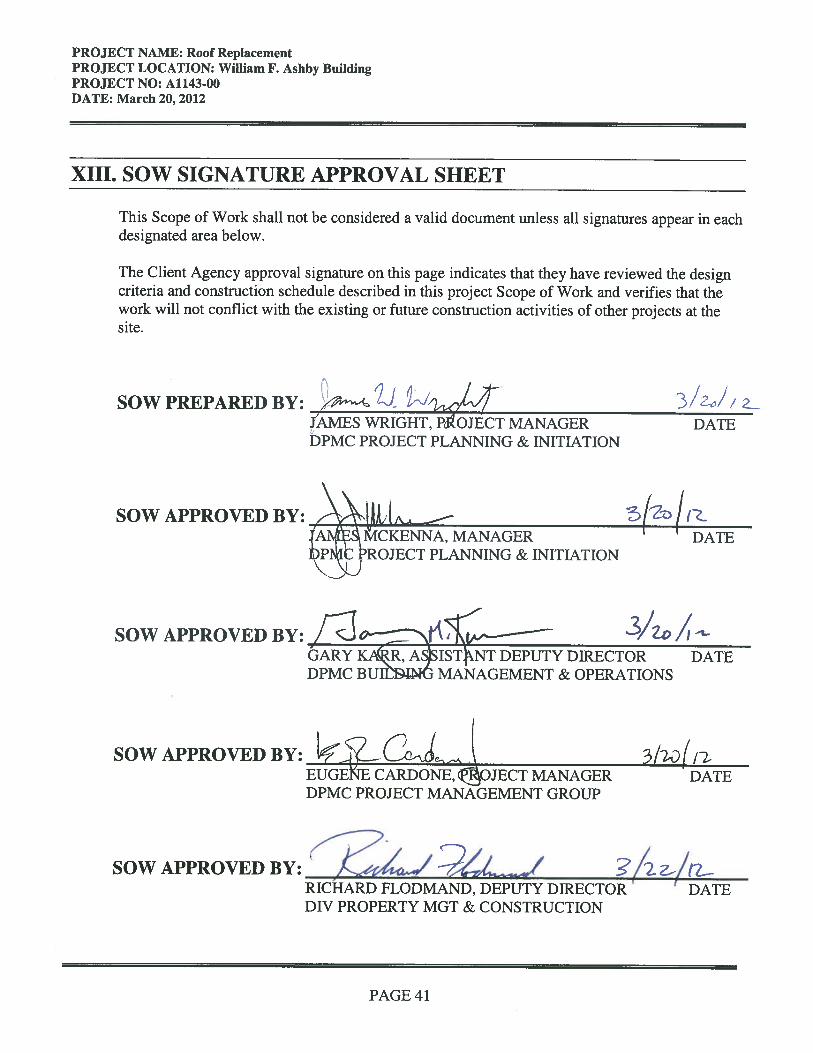
PROJECT NAME: Roof Replacement PROJECT LOCATION: William F. Ashby Building PROJECT NO: A1143-00 DATE: March 20, 2012
PAGE 42
XIV.CONTRACT DELIVERABLES The following is a listing of Contract Deliverables that are required at the completion of each phase of this project. The Consultant shall refer to the DPMC publication entitled, “Procedures for Architects and Engineers,” Volumes I and II, 2nd Edition, dated January, 1991 to obtain a more detailed description of the deliverables required for each item listed below. The numbering system used in this “Contract Deliverables” section of the scope of work corresponds to the numbering system used in the “Procedures for Architects and Engineers” manual and some may have been deleted if they do not apply to this project. DESIGN DEVELOPMENT PHASE: 50% Complete Design Documents (Minimum) 7.1 Project Schedule (Update Bar Chart Schedule) 7.2 Meetings & Minutes (Minutes within 5 working days of meeting) 7.3 Correspondence 7.4 Submission Requirements 7.4.1 A/E Statement of Site Visit, As-Built Drawing Verification (if available) 7.4.2 Space Analysis 7.4.3 Special Features Description: special structural features, etc. 7.4.7 Design Sketches 7.4.8 Regulatory Agency Approvals 7.4.9 Confirm Utility Availability Roof Drains 7.4.10 Drawings: 6 sets Cover Sheet (See A/E Manual for format) Site Plan Site Utility Plan Roof Plans Elevations Sections/Details Structural Drawings, Seismic Design Load Criteria HVAC Drawings Roof Drain Plumbing Drawings, Pipe Distribution & Riser Details 7.4.11 Specifications: 6 sets (See A/E Manual for format, include Division 1 and edit to
describe the administrative and general requirements of the project) 7.4.12 Current Working Estimate in CSI Format & Cost Analysis 38 Form
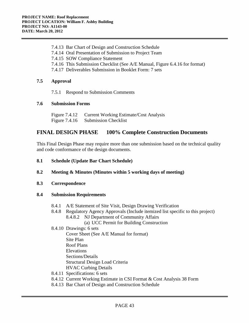
PROJECT NAME: Roof Replacement PROJECT LOCATION: William F. Ashby Building PROJECT NO: A1143-00 DATE: March 20, 2012
PAGE 43
7.4.13 Bar Chart of Design and Construction Schedule 7.4.14 Oral Presentation of Submission to Project Team 7.4.15 SOW Compliance Statement 7.4.16 This Submission Checklist (See A/E Manual, Figure 6.4.16 for format) 7.4.17 Deliverables Submission in Booklet Form: 7 sets 7.5 Approval 7.5.1 Respond to Submission Comments 7.6 Submission Forms Figure 7.4.12 Current Working Estimate/Cost Analysis Figure 7.4.16 Submission Checklist FINAL DESIGN PHASE 100% Complete Construction Documents This Final Design Phase may require more than one submission based on the technical quality and code conformance of the design documents. 8.1 Schedule (Update Bar Chart Schedule) 8.2 Meeting & Minutes (Minutes within 5 working days of meeting) 8.3 Correspondence 8.4 Submission Requirements 8.4.1 A/E Statement of Site Visit, Design Drawing Verification 8.4.8 Regulatory Agency Approvals (Include itemized list specific to this project) 8.4.8.2 NJ Department of Community Affairs (a) UCC Permit for Building Construction 8.4.10 Drawings: 6 sets Cover Sheet (See A/E Manual for format) Site Plan Roof Plans Elevations Sections/Details Structural Design Load Criteria HVAC Curbing Details 8.4.11 Specifications: 6 sets 8.4.12 Current Working Estimate in CSI Format & Cost Analysis 38 Form 8.4.13 Bar Chart of Design and Construction Schedule

PROJECT NAME: Roof Replacement PROJECT LOCATION: William F. Ashby Building PROJECT NO: A1143-00 DATE: March 20, 2012
PAGE 44
8.4.14 Oral Presentation of this Submission to Project Team 8.4.15 Plan Review/SOW Compliance Statement 8.4.16 This Submission Checklist 8.4.17 Deliverables Submission in Booklet Form: 7 sets 8.5 Approvals 8.5.1 Respond to Submission Comments PERMIT APPLICATION PHASE This Permit Application Phase should not include any additional design issues. Design documents shall be 100% complete at the Final Design Phase. 8.6 Permit Application Submission Requirements 8.6.1 - 8.6.7: If all of the deliverables of these sections have been previously submitted to
DPMC and approved there are no further deliverables due at this time 8.6.8 Regulatory Agency Approvals (a) UCC Permit Application & Technical Sub-codes completed by A/E 8.6.9 Utility Availability Confirmation 8.6.10 Signed and Sealed Drawings: 6 sets 8.6.11 Signed and Sealed Specifications: 6 sets 8.6.12 Current Working Estimate/Cost Analysis 8.6.13 Bar Chart Schedule 8.6.14 Project Presentation (N/A this Project) 8.6.15 Plan Review/SOW Compliance Statement 8/6.16 Submission Checklist 8.7 Approvals 8.8 Submission Forms Figure 8.4.12 Current Working Estimate/Cost Analysis Figure 8.4.16 Submission Checklist (Final Review Phase) Figure 8.6.12-b Bid Proposal Form (Form DPMC -3) Figure 8.6.12-c Notice of Advertising (Form DPMC -31) Figure 8.6.16 Submission Checklist (Permit Phase) Figure 8.7 Bid Clearance Form (Form DPMC -601) BIDDING AND CONTRACT AWARD 9.0 Bidding Phase Requirements
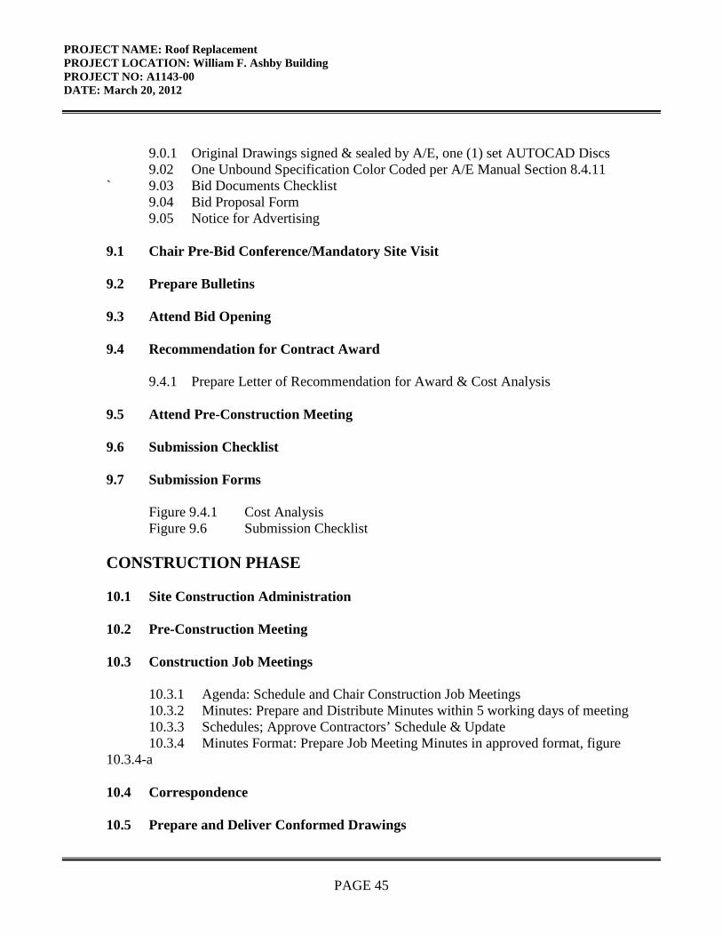
PROJECT NAME: Roof Replacement PROJECT LOCATION: William F. Ashby Building PROJECT NO: A1143-00 DATE: March 20, 2012
PAGE 45
9.0.1 Original Drawings signed & sealed by A/E, one (1) set AUTOCAD Discs 9.02 One Unbound Specification Color Coded per A/E Manual Section 8.4.11 ` 9.03 Bid Documents Checklist 9.04 Bid Proposal Form 9.05 Notice for Advertising 9.1 Chair Pre-Bid Conference/Mandatory Site Visit 9.2 Prepare Bulletins 9.3 Attend Bid Opening 9.4 Recommendation for Contract Award 9.4.1 Prepare Letter of Recommendation for Award & Cost Analysis 9.5 Attend Pre-Construction Meeting 9.6 Submission Checklist 9.7 Submission Forms Figure 9.4.1 Cost Analysis Figure 9.6 Submission Checklist CONSTRUCTION PHASE 10.1 Site Construction Administration 10.2 Pre-Construction Meeting 10.3 Construction Job Meetings 10.3.1 Agenda: Schedule and Chair Construction Job Meetings 10.3.2 Minutes: Prepare and Distribute Minutes within 5 working days of meeting 10.3.3 Schedules; Approve Contractors’ Schedule & Update 10.3.4 Minutes Format: Prepare Job Meeting Minutes in approved format, figure 10.3.4-a 10.4 Correspondence 10.5 Prepare and Deliver Conformed Drawings
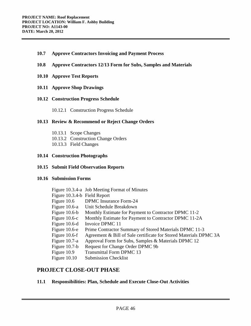
PROJECT NAME: Roof Replacement PROJECT LOCATION: William F. Ashby Building PROJECT NO: A1143-00 DATE: March 20, 2012
PAGE 46
10.7 Approve Contractors Invoicing and Payment Process 10.8 Approve Contractors 12/13 Form for Subs, Samples and Materials 10.10 Approve Test Reports 10.11 Approve Shop Drawings 10.12 Construction Progress Schedule 10.12.1 Construction Progress Schedule 10.13 Review & Recommend or Reject Change Orders 10.13.1 Scope Changes 10.13.2 Construction Change Orders 10.13.3 Field Changes 10.14 Construction Photographs 10.15 Submit Field Observation Reports 10.16 Submission Forms Figure 10.3.4-a Job Meeting Format of Minutes Figure 10.3.4-b Field Report Figure 10.6 DPMC Insurance Form-24 Figure 10.6-a Unit Schedule Breakdown Figure 10.6-b Monthly Estimate for Payment to Contractor DPMC 11-2 Figure 10.6-c Monthly Estimate for Payment to Contractor DPMC 11-2A Figure 10.6-d Invoice DPMC 11 Figure 10.6-e Prime Contractor Summary of Stored Materials DPMC 11-3 Figure 10.6-f Agreement & Bill of Sale certificate for Stored Materials DPMC 3A Figure 10.7-a Approval Form for Subs, Samples & Materials DPMC 12 Figure 10.7-b Request for Change Order DPMC 9b Figure 10.9 Transmittal Form DPMC 13 Figure 10.10 Submission Checklist PROJECT CLOSE-OUT PHASE 11.1 Responsibilities: Plan, Schedule and Execute Close-Out Activities
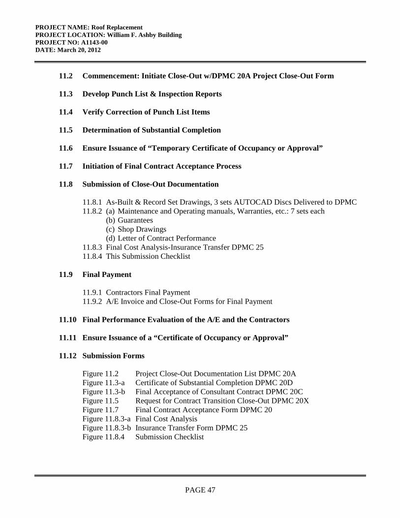
PROJECT NAME: Roof Replacement PROJECT LOCATION: William F. Ashby Building PROJECT NO: A1143-00 DATE: March 20, 2012
PAGE 47
11.2 Commencement: Initiate Close-Out w/DPMC 20A Project Close-Out Form 11.3 Develop Punch List & Inspection Reports 11.4 Verify Correction of Punch List Items 11.5 Determination of Substantial Completion 11.6 Ensure Issuance of “Temporary Certificate of Occupancy or Approval” 11.7 Initiation of Final Contract Acceptance Process 11.8 Submission of Close-Out Documentation 11.8.1 As-Built & Record Set Drawings, 3 sets AUTOCAD Discs Delivered to DPMC 11.8.2 (a) Maintenance and Operating manuals, Warranties, etc.: 7 sets each (b) Guarantees (c) Shop Drawings (d) Letter of Contract Performance 11.8.3 Final Cost Analysis-Insurance Transfer DPMC 25 11.8.4 This Submission Checklist 11.9 Final Payment 11.9.1 Contractors Final Payment 11.9.2 A/E Invoice and Close-Out Forms for Final Payment 11.10 Final Performance Evaluation of the A/E and the Contractors 11.11 Ensure Issuance of a “Certificate of Occupancy or Approval” 11.12 Submission Forms Figure 11.2 Project Close-Out Documentation List DPMC 20A Figure 11.3-a Certificate of Substantial Completion DPMC 20D Figure 11.3-b Final Acceptance of Consultant Contract DPMC 20C Figure 11.5 Request for Contract Transition Close-Out DPMC 20X Figure 11.7 Final Contract Acceptance Form DPMC 20 Figure 11.8.3-a Final Cost Analysis Figure 11.8.3-b Insurance Transfer Form DPMC 25 Figure 11.8.4 Submission Checklist
PROJECT NAME: Roof Replacement PROJECT LOCATION: William F. Ashby Building PROJECT NO: A1143-00 DATE: March 20, 2012
PAGE 48
XV.EXHIBITS The attached exhibits in this section will include a sample project schedule, and any supporting documentation to assist the Consultant in the design of the project such as maps, drawings, photographs, floor plans, studies, reports, etc.
END OF SCOPE OF WORK
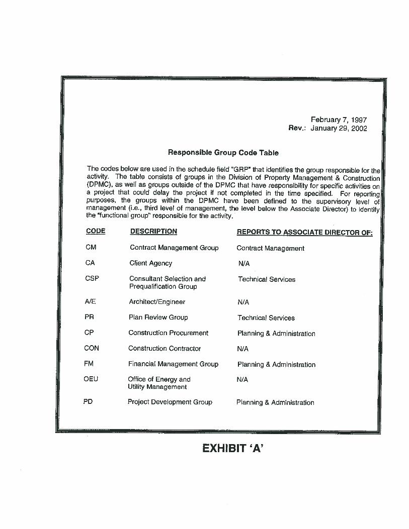
February 7, 1997Rev.: January 29, 2002
Responsible Group Code Table
The codes below are used in the schedule field “GRP” that identifies the group responsible for theactivity. The table consists of groups in the Division of Property Management & Construction(DPMC), as well as groups outside of the DPMC that have responsibility for specific activities ona project that could delay the project if not completed in the time specified. For reportingpurposes, the groups within the DPMC have been defined to the supervisory level ofmanagement (i.e., third level of management, the level below the Associate Director) to identifythe “functional group” responsible for the activity.
CODE DESCRIPTION REPORTS TO ASSOCIATE DIRECTOR OF:
CM Contract Management Group Contract Management
CA Client Agency N/A
CSP Consultant Selection and Technical ServicesPrequalitication Group
AlE ArchitectlEngineer N/A
PR Plan Review Group Technical Services
CP Construction Procurement Planning & Administration
CON Construction Contractor N/A
FM Financial Management Group Planning & Administration
OEU Office of Energy and N/AUtility Management
PD Project Development Group Planning & Administration
EXHIBIT ‘A’
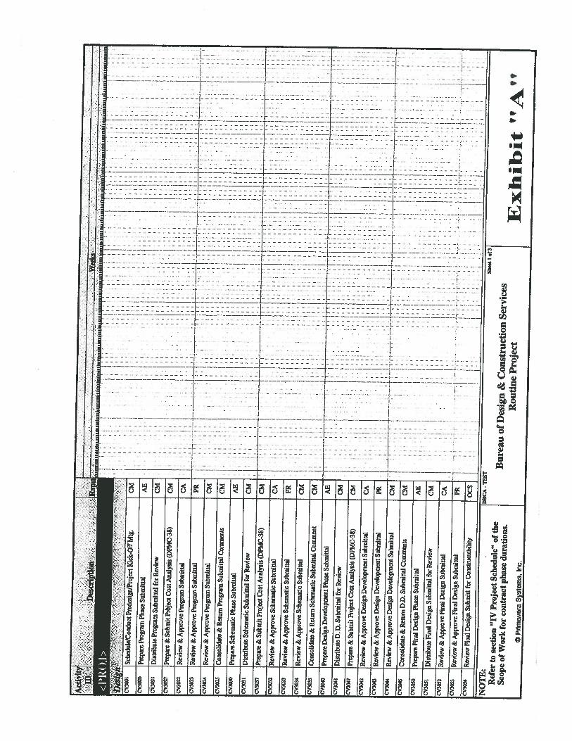
Act
ivity
rn..
IS
ulo
uct
Pted
esig
n/Pr
ojec
t
UI
CM
CV
3020
Prep
are
Prog
ram
Phas
eSu
bmitt
alA
BC
V3O
2iD
istr
ibut
ePr
ogra
mSu
bmitt
alfor
Revie
wC
M
CV3O
Z7Pr
epar
e &S
ubm
itPr
bjec
tCos
t Ana
lysi
s(D
PM
C.3
8)
CM
CV
3022
::v30
23
Rev
iew
&A
pprove
Program
Subm
itta
l
Rev
iew
&A
ppro
vePr
ogra
mSu
bmitt
al
1.
.3
3.
CA
II
33
3,
II
I—
S
3II
SI
.3
5I
II
II
1.:
135
II
PRV
3O24
Rev
iew
&A
pprove
Prog
ram
Subm
ittal
CM
CV
3025
Con
solid
ate
&R
etu
rn
Program
Subm
ittal
Co
mm
en
tsC
MCV
3030
Prep
are
Sche
mat
icP
hase
Subm
ittal
AB
CV
3031
Dis
tribu
teSc
hem
atic
Subm
itta
lfor
Revie
w
II
I
33.’
CM
II.
-I
II,.
3:
I.
1
535333
.1
CV
3031
Prep
are
&Su
bmit
Proj
ect C
ostA
naly
sis
(DPM
C35
)C
M4—
CV30
32R
evie
w&
App
rove
Sche
mat
icSu
bmitt
alC
A3
1C
V30
33R
evie
w&
App
rove
Sche
mat
icSu
bmitt
al1
I:_j.
,.
33
5,
.4.
11133
II—
:.
1ii
1i.
Rev
iew
&A
ppro
veSc
hem
atic
Subm
ittal
CM
Cv30
35C
onso
lidat
e&
Ret
urn
Sche
mat
icSu
bnuf
lalC
omm
ent
CM
I—
-___--.
—L
..-_
•_.-__.__-.
CV
3040
Prep
are
Desig
nD
evel
opm
ent P
hase
Subm
ittal
AE
—33335
:I
II
ii
IIiII.’
4;
IS
i
CV
3041
Dis
trib
uteD
1)Su
bmitt
alfo
rkev
iew
CM
1C
V30
47Pr
epar
eSr
Subm
itPr
ojec
t Cos
tAna
lysi
s(D
PMC
38)
CM
iç
I
CV
3042
Rev
iew
&A
ppro
veD
esig
nD
evel
opm
ent S
ubm
ittal
CA
II
I1
3C
V30
43R
evie
w&
App
rove
Des
ign
Dev
elop
men
t Sub
mitt
alPR
33
IC
V30
44R
evie
w&
App
rove
Des
ign
Dev
elop
men
t Sub
mitt
alC
MI
II
—
CV
3045
Con
solid
ate
&R
etur
nD
DSu
bmitt
alC
omm
ents
CM
CV3O
5OPr
epar
eFi
nal D
esig
nPh
ase
Subm
ittal
AE
II
CVSO
SID
istr
ibut
eFi
nalD
esig
nSu
bmitt
alfo
rRev
iew
CM
Ic3
Rev
iew
SrA
ppro
veFi
nalD
esig
nSu
bmitt
alC
AI
CV
3053
Rev
iew
&A
ppro
veFi
nal
Des
ign
Subm
ittal
PRC
V30
54R
evie
wFm
alD
esig
nSu
bini
tifo
rCon
stni
ctab
ility
OC
S
NO
TE
:—
Shee
t it3
Ref
erto
sect
ion
“IV
Pro
ject
Sch
edul
e”of
the
Bure
auof
Des
ign
&C
onst
ruct
ion
Serv
ices
Scop
eof
Wor
kfo
rco
ntra
ctph
ase
dura
tion
s.R
outi
neP
roje
ctI
Xli
i bit
“?
©P
rlm
aver
aS
yste
ms,
Inc.
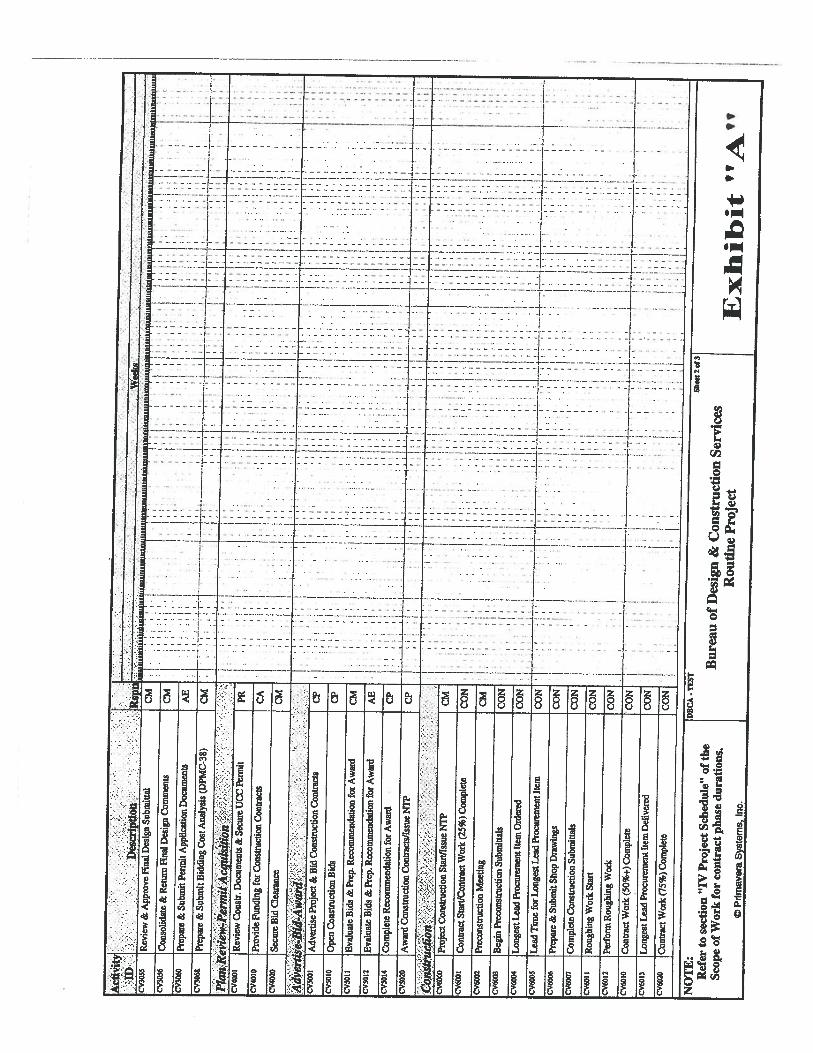
III I
g.
S
aCa.II I I.
I
a
I.I
I
III
I
E
a
III
IS
C
I •1
I
IS
C
I
2
.
_I3C:
[I5.
1
o—
1I• ‘VC
eM
w
N
O0.
f:‘IVV —V
-
......
V
•:.
-•-.:-I;•-
•—
-...
-
V——I-—-.V—•_____V__V——V—V
.4
--
-
-
V_I—
——I—
—V “1’•
r—--——t-
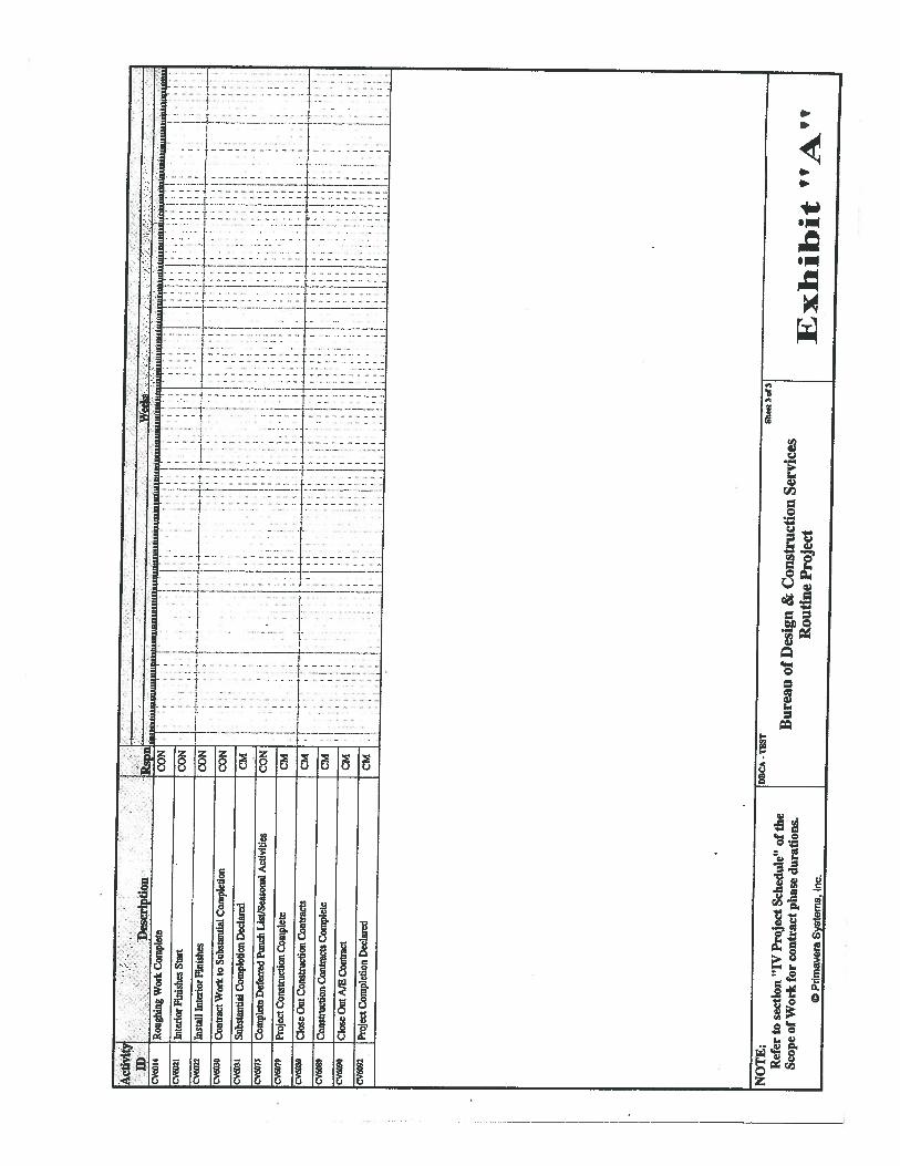
z
-
a
Ia
0
9
Cl,
030
C)
r)
0
I IF•1
O
Ia
9
00
ng
0
•1I
ir:l::
----.--.----4-
::H:T:Z
--
—---—-—-—--———--t—-
f.
::::tz•---_
-+----::::4:.
—I
4
zz:
—I—
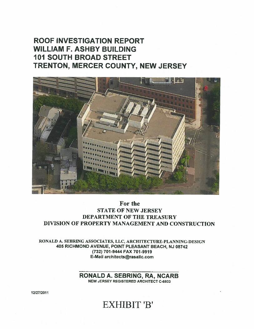
ROOF INVESTIGATION REPORTWILLIAM F. ASHBY BUILDING101 SOUTH BROAD STREETTRENTON, MERGER COUNTY, NEW JERSEY
For theSTATE OF NEW JERSEY
DEPARTMENT OF THE TREASURYDIVISION OF PROPERTY MANAGEMENT AND CONSTRUCTION
RONALD A. SEBRING ASSOCIATES, LLC, ARCHITECTURE-PLANNING-DESIGN405 RICHMOND AVENUE, POINT PLEASANT BEACH, NJ 08742
(732) 701-9444 FAX 701-9919E-Mail [email protected]
1212712011
RONALD A. SEBRING, RA, NCARBNEW JERSEY REGISTERED ARCHITECT C-6933
EXHIBIT ‘B’
INTRODUCTION:
The William F. Ashby Building, constructed about 1985 is located at 101 Broad Street in Trenton,New Jersey. The building is an 8-story, steel framed structure containing approximately 47,201square feet gross floor area. The building is currently occupied as offices for the New JerseyDepartment of Community Affairs.
Ronald A. Sebring Associates, LLC (RASA) was commissioned by the New Jersey, Department of theTreasury, Division of Property Management and Construction, to conduct a physical conditions surveyand prepare a report to identify the source of leaks, locate and identify observable roof defects, and,through nuclear gauge moisture testing, identify areas where moisture has entered the roofing system.Recommendations for repair and/or replacement, along with construction cost estimates are to beincluded in the report.
Members of RASA and Jersey Infrared Consultants, a DPMC pre-qualified testing firm, visited theroof on multiple occasions to field measure the roof, conduct a survey of the existing conditions, andto conduct nuclear gauge moisture testing.
ROOF CONSTRUCTION:
The roof system consists of a single ply, loose laid, EPDM membrane, ballasted with river rock, overtapered rigid insulation, over 1 ‘/2” metal decking. The original construction documents indicate thatthe roofing system is to meet the requirements of one hour firerated assembly U.L. Des. No. P711 orP801. Both systems require spray-applied fireproofing on the underside of the deck and structuralroof framing. Care must be taken during roof replacement or roof repair work to not disturb theexisting fireproofing. If disturbed, the fireproofing must be repaired by a licensed applicator.
The total roof area is approximately 25,200 square feet. There are HVAC units that are mounted onsolid curbs that occupy approximately 1,280 square feet leaving a total of approximately 23,920square feet of roof membrane. 18” square by I 3/4 thick concrete walkpads are in place around theHVAC units and the roof perimeter.
High (6’-6 ‘/2”+/- above top of steel deck) and low (1’-lO”+/- above top of steel deck) parapet wallsenclose the roof perimeter. The parapet wall is surfaced with EPDM membrane flashing bonded torigid insulation or plywood. A prefinished pre-fabricated metal coping is in place over the parapetwall. The coping will need to be removed and reset or replaced if the roof system is replaced to allowthe new flashings to properly extend over the parapet wall substrate.
TEST CUTS AND PROBES
Areas surveyed to have high or low moisture readings during the nuclear gauge moisture testing wereprobed to confirm the moisture test results.
ROOF INVESTIGATION REPORT 1 12/27/11WILLIAM ASHBY BUILDING
EXHIBIT ‘B’
NUCLEAR FLAT ROOF MOISTURE SURVEY
A nuclear flat roof moisture survey was conducted on November 8th 2011. Readings were taken at 71/2’ intervals and transferred to a scaled map that is included in the Nuclear Flat Roof MoistureSurvey Report, prepared by Jersey Infrared Consultants, presented in Appendix “C”. Four (4) separateareas of moisture damage were found during the survey and are identified on the map referencedabove and also on the Roof Plan presented in Appendix “A”. Moisture probes confirmed the presenceof moisture in each of the areas. The total area of moisture damage is approximately 225 square feet.From overlaying the roof and floor plans, two (2) of the moisture damaged areas correlate directly toknown water leakage locations on the 8tl floor. One location is in the Commander’s Office bathroomand the other is within Room 824.
The approximate 225 square feet of moisture damaged area represents a total of .94% of the entire roofarea.
GENERAL CONDITIONS:
The 8th floor was reviewed for water infiltration with the building’s maintenance personnel. The leakson the 8th floor were indentified and noted. The approximate locations were transferred onto the RoofPlan presented in Appendix “A”. Most areas have been leak free in recent months except for RoomNo.872b which has water leaking down the wall adjacent to the elevator shaft. It was noted that,during heavy rains, Room No.81 2b may also experience water infiltration. It was observed that, aboveRoom No.827b, the original base flashing, which has not been repaired, is delaminating at the bottomof the flashings. See photo No. 26. Above Room No.812b, the base flashings, previously partiallyrepaired, are opening at the roof level. See photo No. 35.
Although the condition of the actual membrane is fair, there are a number of deficiencies. They arenoted as follows:
• Greater than 50% of the original lap sealant around flashings and on seams is in failure. (50%-75%)
• Many of the seams between the roof membrane sheets are delaminating. Typically, the 4”wide overlapped seams are open approximately ¼”. The actual amount of delaminated seamscannot be determined without removal of the river rock ballast. Based on observations of thevisible roof surface it is estimated that approximately 20% of the seams may be delaminating.Photograph No.23 shows typical delamination of seam.
• Approximately 30% of original base flashings have failed. Of the failed flashings,approximately 95% have been previously repaired. Much of the older repairs are at the startof failure. Approximately 15% of the previous repairs are beginning to fail and 85% of therepairs appear to be stable.
• There are multiple repairs and improper uses of lap sealant, membrane, and membraneflashings. Pitch pockets are in failure.
• Slope and drainage appear adequate.
• The existing exterior building sealants appear to be in satisfactory condition.
ROOF INVESTIGATION REPORT 2 12/27/11WILLIAM ASHBY BUILDING
EXHIBIT ‘B’

• The lightning protection system has minor damage. The location is identified on the RoofPlan.
• The prefinished metal copings are in satisfactory condition.
• Rail curb metal cap flashings are rusted and in very poor condition.
• Flashing at the top of the Rooftop HVAC units curbs is rusted and in poor condition. Somecurbs have been previously repaired with EPDM membrane flashing.
• Ballast stone is missing from some areas of the roof that were previously repaired.Approximately 85%-90% of the roof is properly covered with ballast stone. The ballast isrequired to prevent lifting of the roofing system components in high wind conditions.
SHORT RANGE RECOMMENDATIONS:
The observed defects, noted on the Roof Plan presented in Appendix “A” should be repaired as soonas possible. The estimated cost of the necessary repairs is $10,750.
This work includes:
• The cutting out and replacement of the moisture damaged insulation detected by the nuclearmoisture testing.
• Repair of delaminating and open seams in EPDM membrane roof and flashings. New 6” or12” wide fully cured EPDM pressure sensitive cover strips should be installed over the failedseams. The existing membrane surface should be cleaned and primed in accordance with theroofing manufacturer’s instructions prior to application of the cover strips.
• Repair of pitch pockets using elastoform flashing.
• Preparing and painting galvanized steel rail curb and HVAC unit curb caps with rust-inhibitive paint.
At locations of active leaks, where no rooftop defects were observed, or, where after repairs are madeto known defects, the leaks re-occur, the rooftop areas should be further reviewed by removal andresetting of paving stones and river rock ballast as necessary and water testing conducted to identifithe source of the leaks.
LONG RANGE RECOMMENDATIONS:
The roofing and flashing membranes are in fair condition, however, it is anticipated that seamdelamination, opening of seams, and deterioration of water block will continue over time. Inspectionsshould be made at least bi-annually to identi’ readily observable defects. Approximately $5,000should be budgeted annually for maintenance repairs and for emergency repairs due to roof leaks.
ROOF INVESTIGATION REPORT 3 12/27/11BUILDING EXHIBIT ‘B
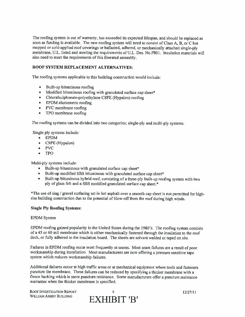
The roofing system is out of warranty, has exceeded its expected lifespan, and should be replaced assoon as funding is available. The new roofing system will need to consist of Class A, B, or C hotmopped or cold-applied roof coverings or ballasted, adhered, or mechanically attached single-plymembrane, U.L. listed and meeting the requirements of U.L. Des. No.P801. Insulation materials willalso need to meet the requirements of this firerated assembly.
ROOF SYSTEM REPLACEMENT ALTERNATIVES:
The roofing systems applicable to this building construction would include:
• Built-up bituminous roofing• Modified bituminous roofing with granulated surface cap sheet*• Chloralsulphonate-polyethylene CSPE (Hypalon) roofing• EPDM elastomeric roofing• PVC membrane roofing• TPO membrane roofing
The roofing systems can be divided into two categories; single-ply and multi-ply systems.
Single ply systems include:• EPDM• CSPE (Hypalon)• PVC• TPO
Multi-ply systems include:• Built-up bituminous with granulated surface cap sheet*• Built-up modified SBS bituminous with granulated surface cap sheet*• Built-up bituminous hybrid roof, consisting of a three-ply built-up roofing system with two
ply of glass felt and a SBS modified granulated surface cap sheet.*
*The use of slag / gravel surfacing set in hot asphalt over a smooth cap sheet is not permitted for high-rise building construction due to the potential of blow-off from the roof during high winds.
Single Ply Roofing Systems:
EPDM System
EPDM roofing gained popularity in the United States during the 1980’s. The roofing system consistsof a 45 or 60 mu membrane which is either mechanically fastened through the insulation to the roofdeck, or fully adhered to the insulation board. The sheets are solvent welded or taped on site.
Failures in EPDM roofing occur most frequently at seams. Most seam failures are a result of poorworkmanship during installation. Most manufacturers are now offering a pressure sensitive tapesystem which reduces workmanship failures.
Additional failures occur at high traffic areas or at mechanical equipment where tools and fastenerspuncture the membrane. These failures can be reduced by specifying a thicker membrane with afleece backing which is more puncture resistance. Some manufacturers offer a puncture resistancewarrantee when the thicker membrane is specified.
ROOF INVESTIGATION REPORT 4 12/27/11WILLIAM ASHBY BUILDING
EXFIIBJT
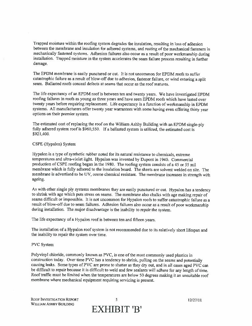
Trapped moisture within the roofing system degrades the insulation, resulting in loss of adhesionbetween the membrane and insulation for adhered systems, and rusting of the mechanical fasteners inmechanically fastened systems. Adhesion failures also occur as a result of poor workmanship duringinstallation. Trapped moisture in the system accelerates the seam failure process resulting in furtherdamage.
The EPDM membrane is easily punctured or cut. It is not uncommon for EPDM roofs to suffercatastrophic failure as a result of blow-off due to adhesion, fastener failure, or wind entering a splitseam. Ballasted roofs conceal defects at seams that occur as the roof matures.
The life expectancy of an EPDM roof is between ten and twenty years. We have investigated EPDMroofing failures in roofs as young as three years and have seen EPDM roofs which have lasted overtwenty years before requiring replacement. Life expectancy is a function of workmanship in EPDMsystems. All manufacturers offer twenty year warrantees with some having even offering thirty yearoptions on their premier system.
The estimated cost of replacing the roof on the William Ashby Building with an EPDM single-plyfully adhered system roof is $960,550. If a ballasted system is utilized, the estimated cost is$921,400.
CSPE (Hypalon) System
Hypalon is a type of synthetic rubber noted for its natural resistance to chemicals, extremetemperatures and ultra-violet light. Hypalon was invented by Dupont in 1940. Commercialproduction of CSPE roofing began in the 1980. The roofing system consists of a 45 or 55 milmembrane which is fully adhered to the insulation board. The sheets are solvent welded on site. Themembrane is advertised to be UV, ozone chemical resistant. The membrane increases in strength withageing.
As with other single ply systems membranes they are easily punctured or cut. Hypalon has a tendencyto shrink with age which puts stress on seams. The membrane also chalks with age making repair ofseams difficult or impossible. It is not uncommon for Hypalon roofs to suffer catastrophic failure as aresult of blow-off due to seam failures. Adhesion failures also occur as a result of poor workmanshipduring installation. The major disadvantage is the inability to repair the system.
The life expectancy of a Hypalon roof is between ten and fifteen years.
The installation of a Hypalon roof system is not recommended due to its relatively short lifespan andthe inability to repair the system over time.
PVC System
Polyvinyl chloride, commonly known as PVC, is one of the most commonly used plastics inconstruction today. Over time PVC has a tendency to shrink, pulling on the seams and potentiallycausing leaks. Some types of PVC are prone to shatter as they dry out, and in all cases aged PVC canbe difficult to repair because it is difficult to weld and few sealants will adhere for any length of time.Roof traffic must be limited when the temperatures are below 50 degrees making it an unsuitable roofmembrane where mechanical equipment requiring servicing is present.
ROOF INVESTIGATION REPORT 5 12/27/11WILLIAM ASHBY BUILDING
EXHIBIT ‘B’
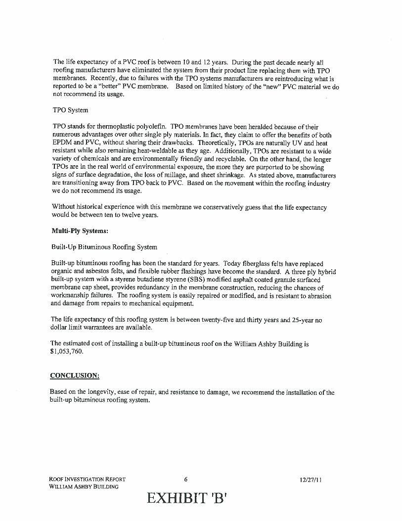
The life expectancy of a PVC roof is between 10 and 12 years. During the past decade nearly allroofing manufacturers have eliminated the system from their product line replacing them with TPOmembranes. Recently, due to failures with the TPO systems manufacturers are reintroducing what isreported to be a “better” PVC membrane. Based on limited history of the “new” PVC material we donot recommend its usage.
TPO System
TPO stands for thermoplastic polyolefin. TPO membranes have been heralded because of theirnumerous advantages over other single ply materials. In fact, they claim to offer the benefits of bothEPDM and PVC, without sharing their drawbacks. Theoretically, TPOs are naturally UV and heatresistant while also remaining heat-weldable as they age. Additionally, TPOs are resistant to a widevariety of chemicals and are environmentally friendly and recyclable. On the other hand, the longerTPOs are in the real world of environmental exposure, the more they are purported to be showingsigns of surface degradation, the loss of millage, and sheet shrinkage. As stated above, manufacturersare transitioning away from TPO back to PVC. Based on the movement within the roofing industrywe do not recommend its usage.
Without historical experience with this membrane we conservatively guess that the life expectancywould be between ten to twelve years.
Multi-Ply Systems:
Built-Up Bituminous Roofing System
Built-up bituminous roofing has been the standard for years. Today fiberglass felts have replacedorganic and asbestos felts, and flexible rubber flashings have become the standard. A three ply hybridbuilt-up system with a styrene butadiene styrene (SBS) modified asphalt coated granule surfacedmembrane cap sheet, provides redundancy in the membrane construction, reducing the chances ofworkmanship failures. The roofing system is easily repaired or modified, and is resistant to abrasionand damage from repairs to mechanical equipment.
The life expectancy of this roofing system is between twenty-five and thirty years and 25-year nodollar limit warrantees are available.
The estimated cost of installing a built-up bituminous roof on the William Ashby Building is$1,053,760.
CONCLUSION:
Based on the longevity, ease of repair, and resistance to damage, we recommend the installation of thebuilt-up bituminous roofing system.
ROOF INVESTIGATION REPORT 6 12/27/11WILLIAM ASHBY BUILDING
EXHIBIT ‘B’
APPENDIX “A”
• Roof Plan Drawing
EXHIBIT ‘B’
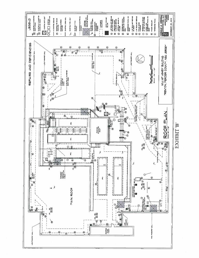
EX
HIB
IT‘B
’
=E
XIS
TIN
GB
RA
CE
EX
ST
ET
CT
IE-B
AC
IC
EX
IST
ING
SC
RE
EN
rn
LE
AC
DA
MA
GE
RE
LC
IU
®L
AP
SE
AL
AN
TR
EP
AIR
aS
PIT
CH
PD
T
©P
RE
VS
EJS
BA
TE
FL
AS
HE
SR
EP
AIR
@V
ER
TIC
AL
SE
AM
SIN
FA
ILU
RE
pM
EM
BR
AN
EP
AT
CS
RE
PA
IRE
NP
AR
AP
ET
©T
RT
CR
AE
EP
AT
CH
05
RO
SE
LA
MS
EA
LA
NT
RE
PA
IRO
NS
EA
M
©L
AP
SE
AL
AN
TR
EP
AIR
FA
ILE
DE
AS
EF
LA
SH
ES
@M
EM
ER
AT
BFL
AN
GIN
GA
TT
OP
SE
RE
IC
UR
E
OL
OO
SE
LA
IDM
EII
ER
AR
EP
AT
CH
ON
RO
SE
Ig>
FA
ILE
DS
EU
LA
NT
TE
TtR
AE
EP
AT
CH
EP
AIc
RS
AN
DD
EC
IEN
CIE
SL
EG
EN
DR
DS
XIN
TE
S6”
DIA
ME
TE
RR
OD
ED
RA
IN
DO C
TE
XIS
TIN
GA
”D
IAM
ET
ER
EA
DV
ES
EL
OU
DR
AIN
EV
IST
ES
ST
CT
L.U
S4T
O0
1JE
XIS
TE
D—
CU
T-1A
UST
FAN
_P
________
r
©O
DR
CDIbrfi
III
B
___
r
DA
MA
GE
DE
4_///I
HL
I-lI
NE
SV
IP
RO
TE
CT
ION
II
IC
AE
LE
—Ir
-—--
II.i
0
MA
INW
OR
D
ET
C
H
!ST
Flr
TIT
G$
©-i
l-i
I\
DR
AIN
11$
IE
XIS
TIN
GU
”D
IAM
ET
ER
II
RO
CF
CR
WN
©1
I
HI
1
I©
JLIJ
II
I:I
U’
IE
1I
____
I©
L_
RT
U
EX
IST
ES
EL
EV
AT
OR
EX
IST
ING
CU
RE
RA
IL
EX
IST
ED
PIP
EV
EN
T
OF
FE
DIT
ED
PIT
CU
PC
OT
ET
EX
IST
ING
EL
EC
TR
ICA
LC
ON
DU
IT
fMC
TS
lTA
RN
DE
TE
CT
ED
BY
/N
IM
I-C
LE
AR
TE
ST
ED
It—
NE
XIS
TIN
GW
AL
LB
MO
UN
TE
DC
AM
ER
A
®—
PU
DT
ON
RA
PH
RE
FE
RE
NC
ER
EIR
ER
r1
CS
ES
DR
ET
EL
——
JIU
AL
ITPA
DS
4=
0--
n--
---.
..
____________
©
TT
TC
AT
TT
TT
S
I1
rI
Wi
IT
IE
IXN
TIS
CE
RA
CE
-7I
©II
LC
I)rJ
-—zI
I’R
TU
21I
1ri
I©
J>
fl/
JIF
kHL
W’II
FF
:F
i4E
4fl
LO
N/
‘—
-1*=
hI
4®
i©T
®_—
H-
L-’
ilL
IIC
B)R
EL
DA
==
==
_=
==
==
==
==
==
==
IL
—I
LO
WP
AR
AP
ET
WA
LL
II
I—
II
CC
TT
TIS
SIC
SE
RS
“PT
——
—I
F:S
EC
RE
TA
RY
SP
AC
EB
EL
OW
EX
IST
ING
PV
CR
OO
TF
CR
I
t(3
CO
RD
JL
rVW
EO
NG
TR
CT
EC
AC
NT
hH
()
CO
t1IS
SIO
I-E
RE
—-
OF
FIC
ER
AT
SR
CC
M“T
vQ
i-
IR
EL
OC
-\E
XIS
TIN
GP
VC
RO
DE
I0
FO
RL
ISI-
ITSI
NG
I
________________________
A©
,--P
RO
TE
CT
ICS
CIC
-—-P
/-
IR
AW
PA
RA
PE
TW
AL
L©
-//
©•
——
SC
AL
C-
lAG
=I-
AM
-_I_
/-/_1,/r
SIN
RE
LD
SN
CIS
TIN
GB
RA
CE
//
Ii
‘E
r/P
©r=
//L
_©
WIL
I4M
AS
NY
SUIL
=DIN
GL
®—
--‘@
CC
L4
NtR
EN
TC
N,M
ER
CE
RC
UN
fl’
NIEW
JER
SE
YS
CA
LE
:T
C
RO
NA
LD
A.
SE
BR
ING
flA
SS
OC
IA7”E
9,
LL
CV
eTflA
WRE
SSO
N
DE
CE
MB
ER
27.
2011
APPENDIX “B”
• Photographs
EXHIBIT ‘B’
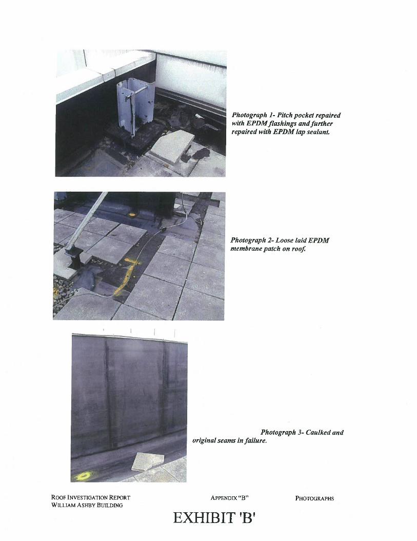
Photograph 1- Pitch pocket repairedwith EPDMflashings andfurtherrepaired with EPDM lap sealant.
Photograph 2- Loose laid EPDMmembrane patch on roof
ROOF INVESTIGATION REPORT
WILLIAM ASHBY BUILDING
APPENDIX “B”
EXHIBIT ‘B’
PHOTOGRAPHS
\
original seams in failure.Photograph 3- Caulked and
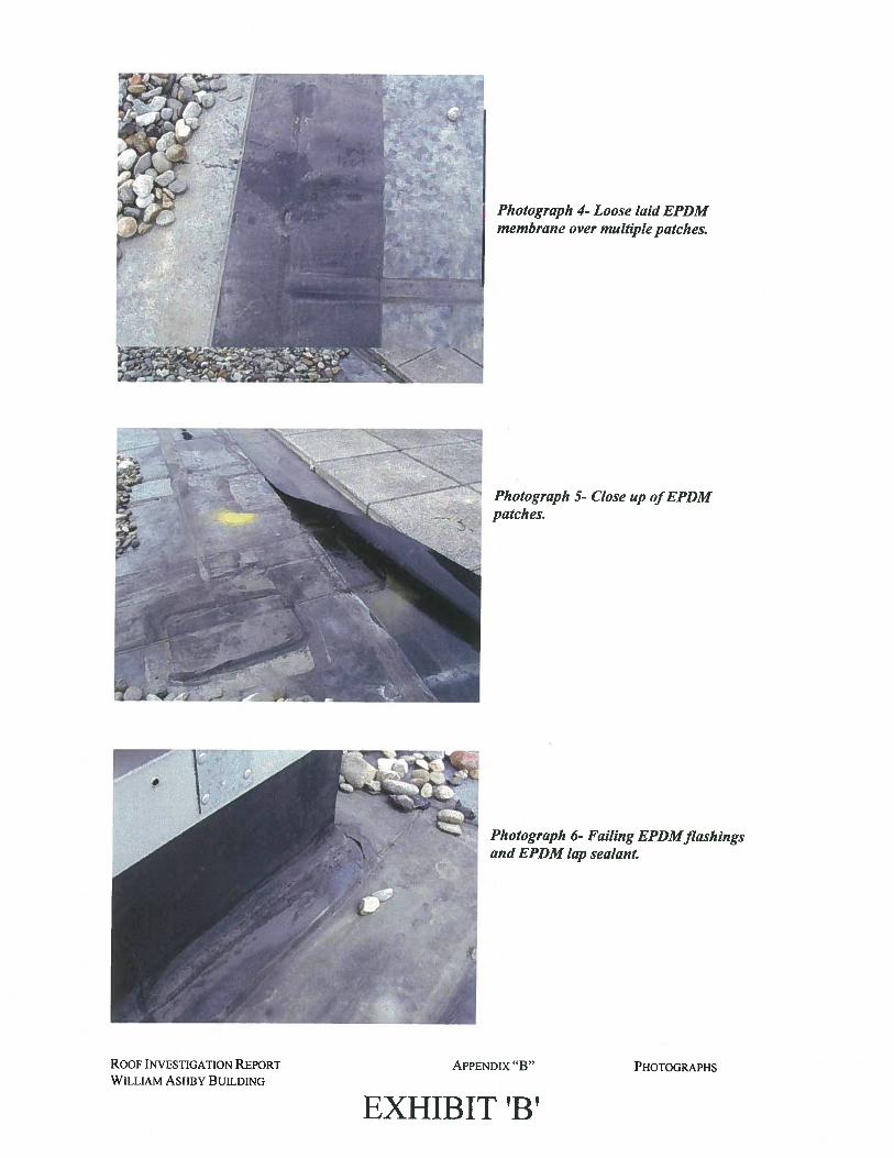
Photograph 4- Loose laid EPDMmembrane over multiple patches.
Photograph 5- Close up ofEPDMpatches.
Photograph 6- Falling EPDMflashingsand EPDM lap sealant.
ROOF INVESTIGATION REPORT
WILLIAM ASHBY BUILDINGAPPENDIX “B”
EXHIBIT ‘B’
PHOTOGRAPHS
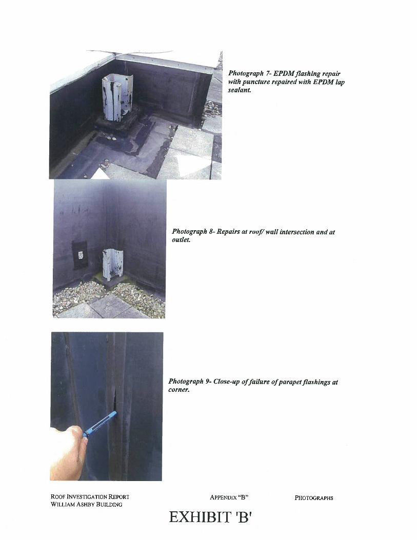
Photograph 7- EPDMflashing repairN with puncture repaired with EPDM lap
sealant.
Photograph 8- Repairs at roof/wall intersection and atoutlet.
Photograph 9- Close-up offailure ofparapetflashings atcorner.
ROOF INVESTIGATION REPORT
WILLIAM ASHBY BUILDING
APPENDIX “B”
EXHIBIT ‘B’
PHOTOGRAPHS
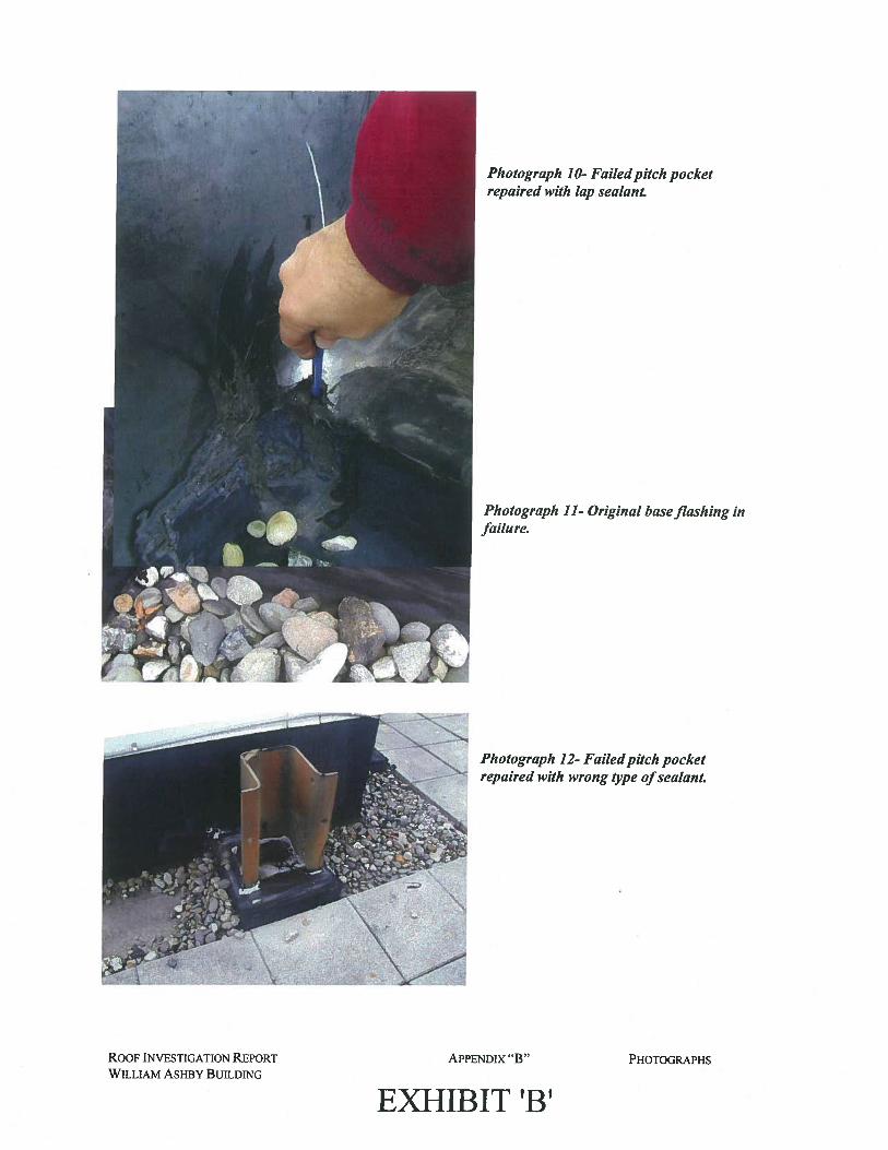
Photograph 10- Failedpitch pocketrepaired with lap sealant.
Photograph 11- Original baseflashing infailure.
Photograph 12- Failedpitch pocketrepaired with wrong type ofsealant.
ROOF INVESTIGATION REPORT
WILLIAM ASHBY BUILDINGAPPENDIX “B”
EXHIBIT ‘B’
PHOTOGRAPHS
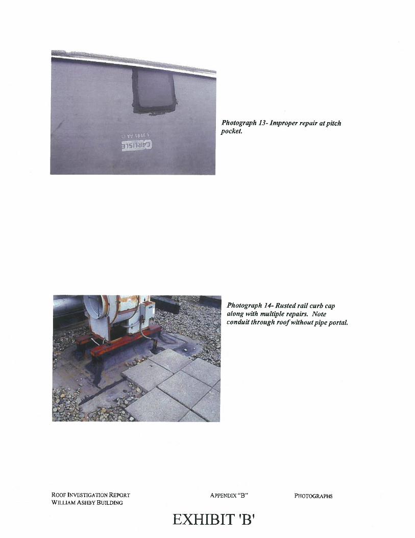
Photograph 13- Improper repair at pitchpocket.
Photograph 14- Rusted rail curb capalong with multiple repairs. Noteconduit through roof withoutpipe portaL
ROOF INVESTIGATION REPORT
WILLIAM ASHBY BUILDING
APPENDIX “B” PHOTOGRAPHS
EXHIBIT ‘W
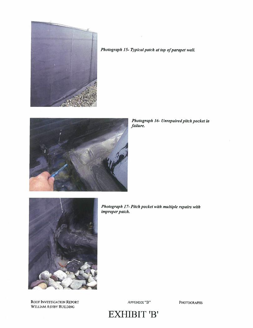
Photograph 15- Typicalpatch at top ofparapet walL
Photograph 16- Unrepairedpitch pocket infailure.
Photograph 17- Pitch pocket with multiple repairs withimproperpatch.
ROOF INVESTIGATION REPORT
WILLIAM AsHBY BUILDING
APPENDIX “B”
EXHIBIT ‘B’
PHOTOGRAPHS
I :
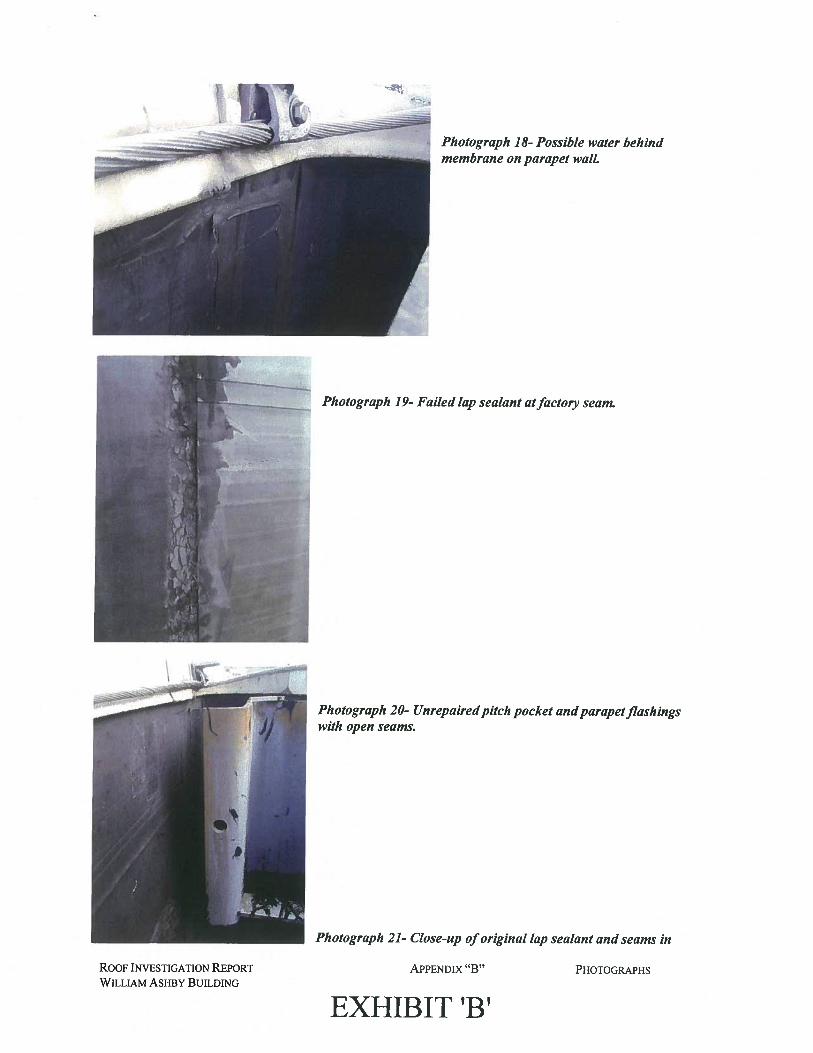
Photograph 18- Possible water behindmembrane on parapet walL
Photograph 19- Failed lap sealant atfactory seam.
Photograph 20- Unrepairedpitch pocket andparapetflashingswith open seams.
Photograph 21- Close-up oforiginal lap sealant and seams in
ROOF INVESTIGATION REPORT
WILLIAM ASHBY BUILDING
APPENDIX “B”
EXHIBIT ‘B’
PHOTOGRAPHS

failure.
Photograph 22- Separation at membraneandpitch pocket.
Photograph 23- Typical seamdelamination atfactory seam.
ROOF INVESTIGATION REPORT
WILLIAM ASHBY BUILDING
APPENDIX “B”
EXHIBIT ‘B’
PHOTOGRAPHS
III
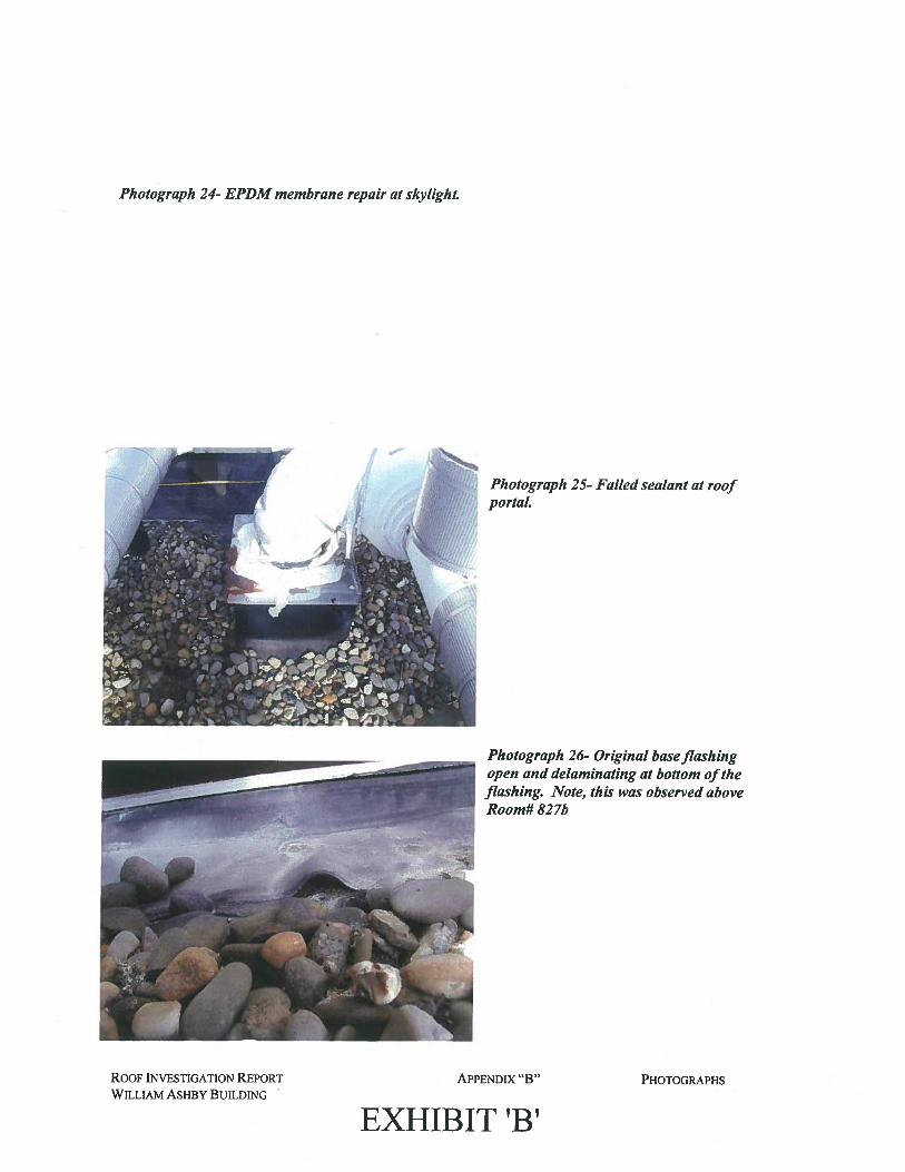
Photograph 24- EPDM membrane repair at skylight.
Photograph 25- Failed sealant at roofportal.
Photograph 26- Original baseflashingopen and delaminating at bottom oftheflashing. Note, this was observed aboveRoom# 827b
ROOF INVESTIGATION REPORT
WILLIAM ASHBY BUILDII’4G
APPENDIX “B”
EXHIBIT ‘B’
PHOTOGRAPHS
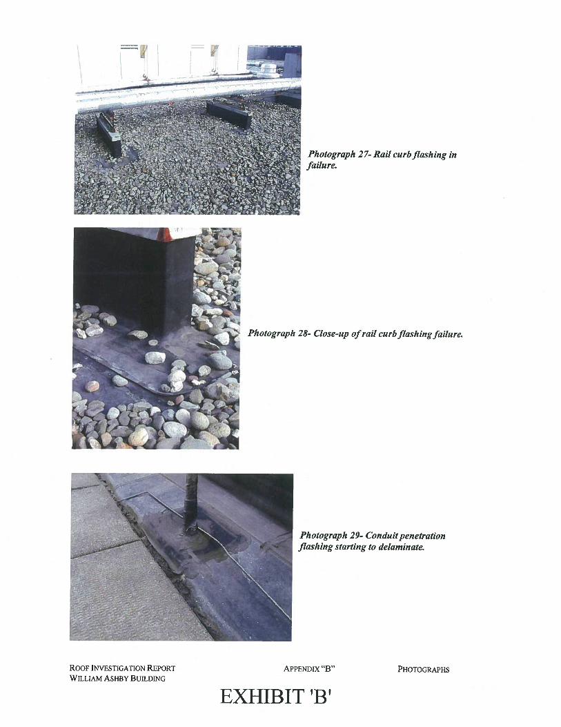
Photograph 27- Rail curb flashing infailure.
Photograph 28- Close-up ofrail curb flashingfailure.
Photograph 29- Conduit penetrationflashing starting to delaminate.
ROOF INVESTIGATION REPORT
WILLIAM ASHBY BUILDING
APPENDIX “B”
EXHIBIT ‘B’
PHOTOGRAPHS
\.ji
:.
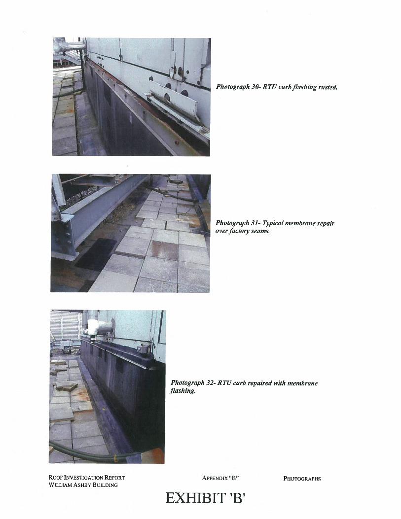
Photograph 30- RTU curb flashing rusted.
Photograph 31- Typical membrane repairover factory seams.
Photograph 32- R TU curb repaired with membraneflashing.
ROOF INVESTIGATION REPORT
WILLIAM ASHBY BUILDING
APPENDIX “B”
EXHIBIT ‘B’
PHOTOGRAPHS
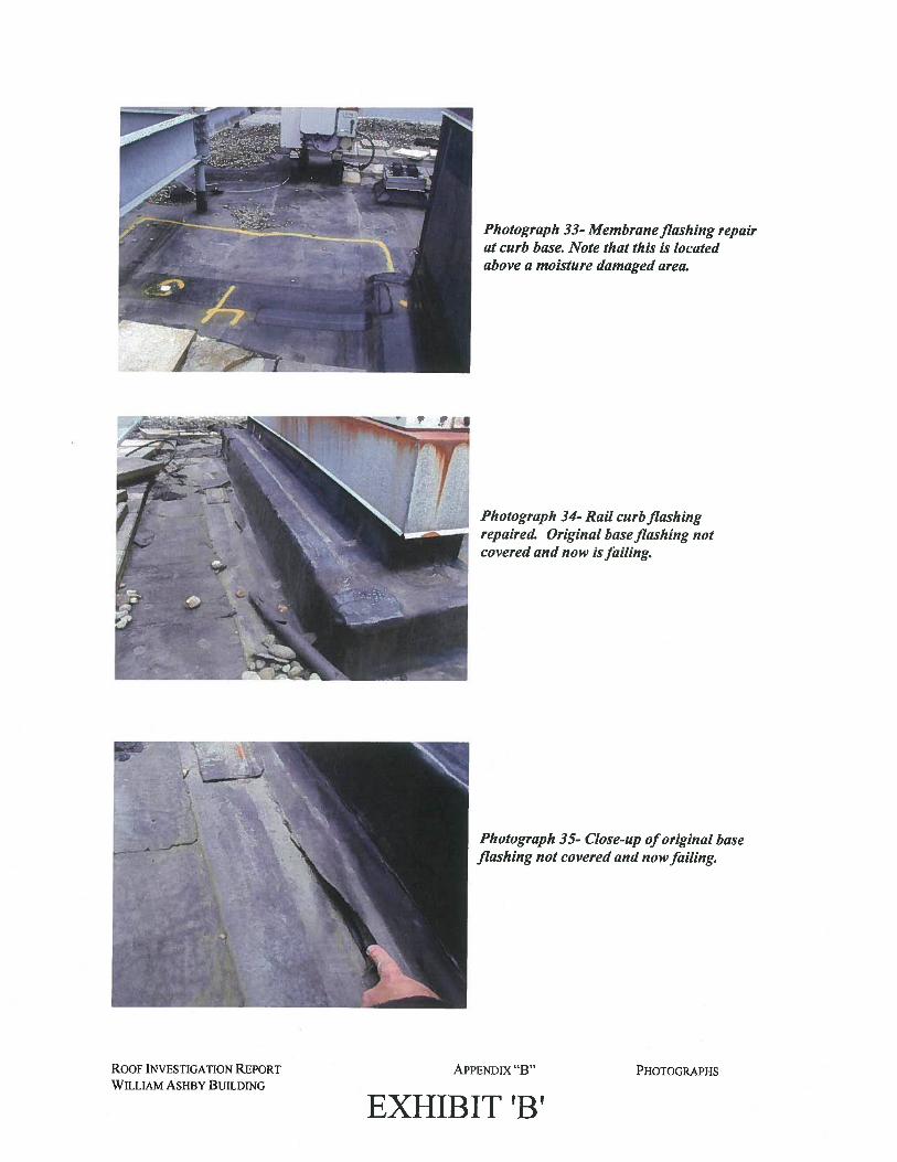
Photograph 33- Membraneflashing repairat curb base. Note that this is locatedabove a moisture damaged area.
Photograph 34- Rail curb flashingrepaired. Original baseflashing notcovered and now isfailing.
Photograph 35- Close-up oforiginal baseflashing not covered and nowfailing.
ROOF INVESTIGATION REPORT
WILLIAM ASHBY BUILDING
APPENDIX “B”
EXHIBIT ‘B’PHOTOGRAPHS
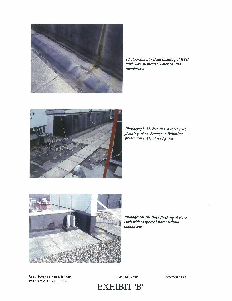
Photograph 36- Baseflashing at RTUcurb with suspected water behindmembrane.
Photograph 37- Repairs at RTU curbflashing. Note damage to lightningprotection cable at roofpaver.
Photograph 38- Baseflashing at RTUcurb with suspected water behindmembrane
ROOF INVESTIGATION REPORT
WILLIAM ASHBY BUILDING
APPENDIX “B”
EXHIBIT ‘B’PHOTOGRAPHS
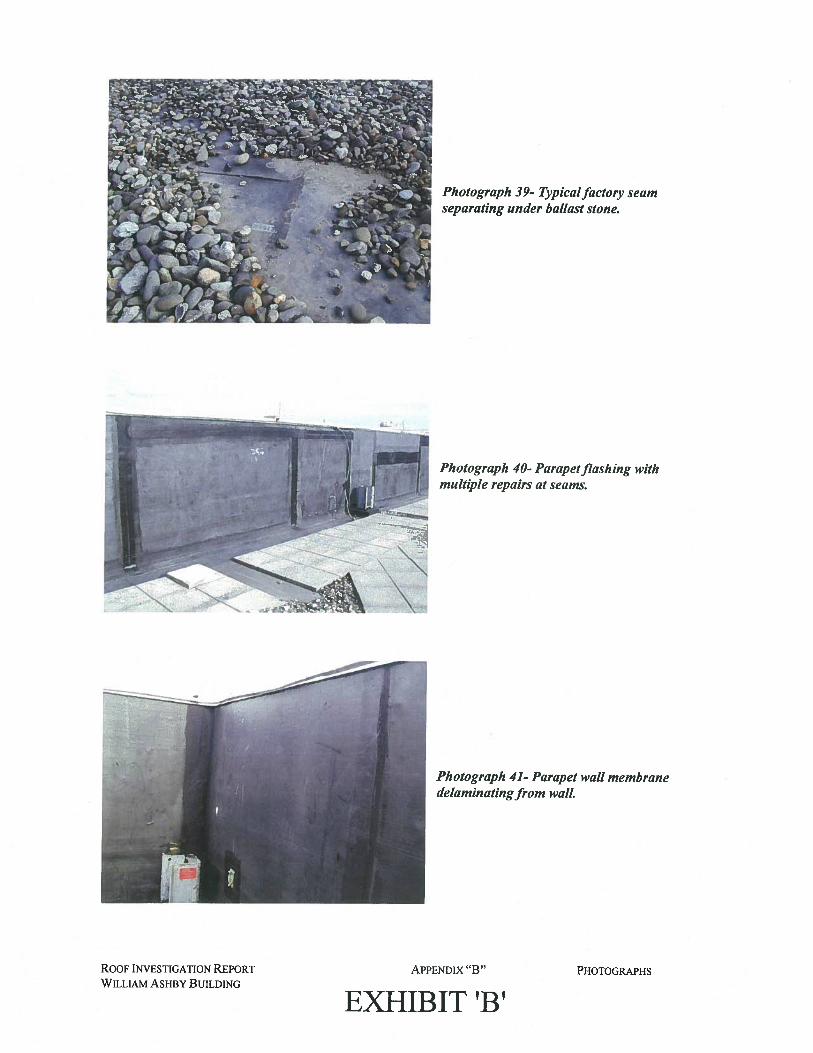
Photograph 39- Typicalfactory seamseparating under ballast stone.
Photograph 40- Parapetflashing withmultiple repairs at seams.
Photograph 41- Parapet wall membranedelaminatingfrom wall.
Roof INVESTIGATION REPORT
WILLIAM ASHBY BUILDING
APPENDIX “B”
EXHIBIT ‘B’PHOTOGRAPHS
-.
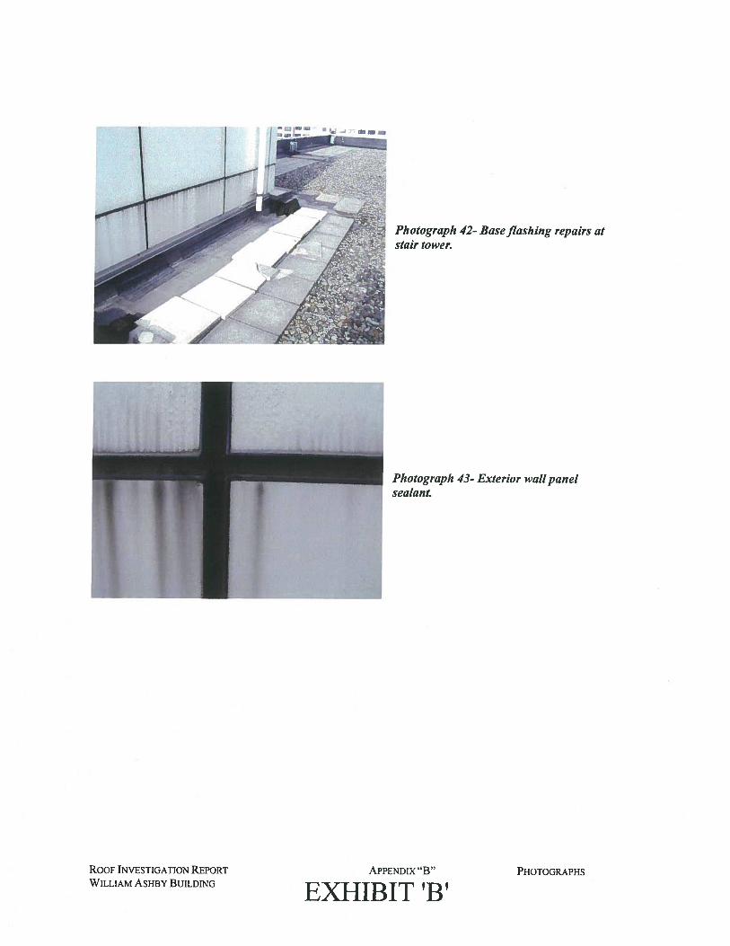
Photograph 42- Baseflashing repairs atstair tower.
Photograph 43- Exterior wallpanelsealant.
ROOF INVESTIGATION REPORT
WILLIAM ASHBY BUILDING
APPENDIX “B”
EXHIBIT ‘B’PHOTOGRAPHS
APPENDIX “C”
• Nuclear Flat Roof Moisture SurveyPrepared by Jersey Infrared Consultants
EXHIBIT ‘B’
__EEE
JERSEY INFRARED CONSULTANTSPhone: (609) 386-1281
Fax: (809) 387-4334
NUCLEAR FLA T ROOF MOISTURE SURVEY
for
Ronald A. Sebring Associates, LLC405 Richmond A venue
Point Pleasant Beach, NJ 08742
at
William Ashby BuildingSouth Broad and Front Streets
Trenton, NJ
November 14, 2011 Our Job Number: 11-1501.7
EXHIBIT ‘B’

JERSEY INFRARED CONSULTANTSPhone (809) 398-1281
Fax: (609) 387.4334
November 14, 2011
David A. ClarkRonald A. Sebring Associates, LLC405 Richmond AvenuePoint Pleasant Beach, NJ 08742
RE: NUCLEAR FLAT ROOF MOISTURE SURVEY REPORTOUR JOB NUMBER: 11-1501.7
Dear Mr. Clark:
Here is our completed report and CD-ROM for the Nuclear Flat Roof Moisture Surveyperformed for Ronald A. Sebring Associates, LLC at the William Ashby Building facility
located at South Broad and Front Streets in Trenton, NJ on November 8, 2011.
Thank you for this opportunity to serve you. If you have any questions or if we can beof further assistance, please feel free to call.
Very truly yours,
Michael CoinLevel IllProject Coordinator
MC:sc
Enclosures
EXHIBIT ‘B’
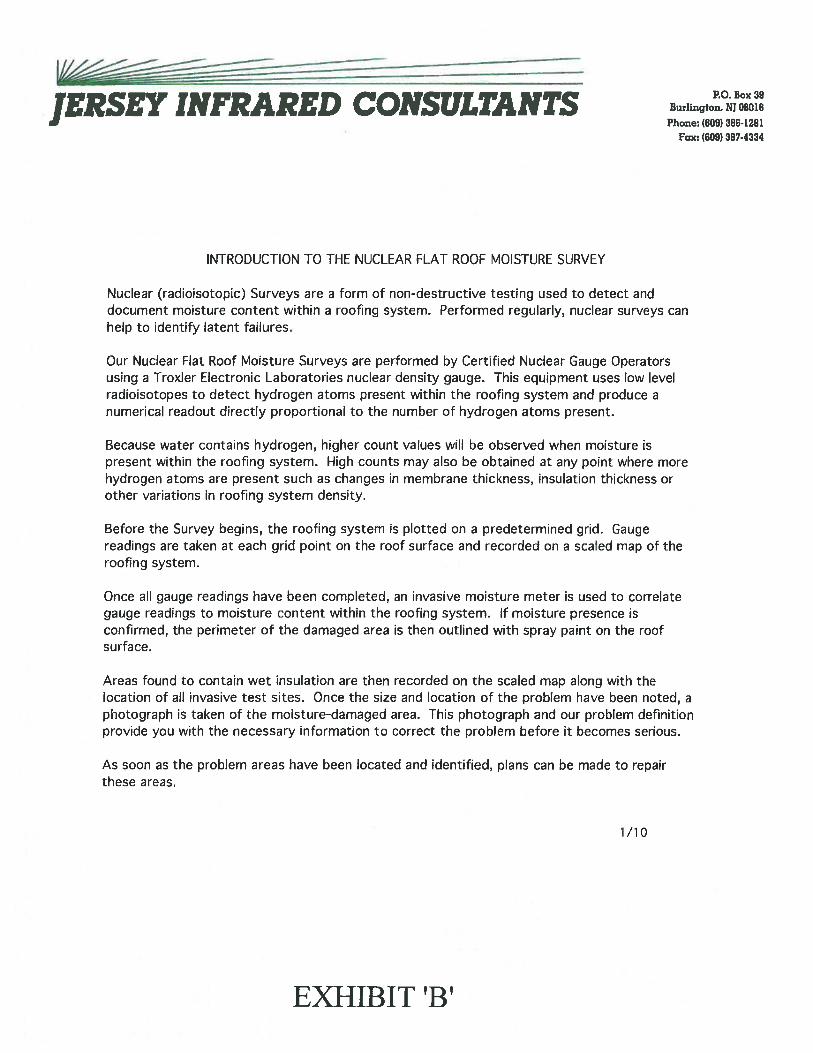
JERSEY INFRARED CONSULTANTSPhone: (609) 386-1281
Fax: (809) 387-4334
INTRODUCTION TO THE NUCLEAR FLAT ROOF MOISTURE SURVEY
Nuclear (radioisotopic) Surveys are a form of non-destructive testing used to detect anddocument moisture content within a roofing system. Performed regularly, nuclear surveys canhelp to identify latent failures.
Our Nuclear Flat Roof Moisture Surveys are performed by Certified Nuclear Gauge Operatorsusing a Troxler Electronic Laboratories nuclear density gauge. This equipment uses low levelradioisotopes to detect hydrogen atoms present within the roofing system and produce anumerical readout directly proportional to the number of hydrogen atoms present.
Because water contains hydrogen, higher count values will be observed when moisture ispresent within the roofing system. High counts may also be obtained at any point where morehydrogen atoms are present such as changes in membrane thickness, insulation thickness orother variations in roofing system density.
Before the Survey begins, the roofing system is plotted on a predetermined grid. Gaugereadings are taken at each grid point on the roof surface and recorded on a scaled map of theroofing system.
Once all gauge readings have been completed, an invasive moisture meter is used to correlategauge readings to moisture content within the roofing system. If moisture presence isconfirmed, the perimeter of the damaged area is then outlined with spray paint on the roofsurface.
Areas found to contain wet insulation are then recorded on the scaled map along with thelocation of all invasive test sites. Once the size and location of the problem have been noted, aphotograph is taken of the moisture-damaged area. This photograph and our problem definitionprovide you with the necessary information to correct the problem before it becomes serious.
As soon as the problem areas have been located and identified, plans can be made to repairthese areas.
1/10
EXHIBIT ‘B’
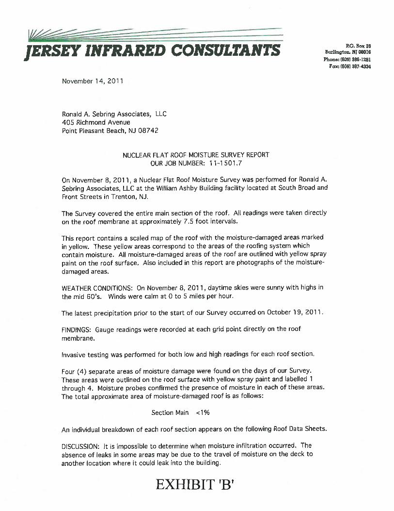
EEEJERSEY INFRARED CONSULTANTS
Phone: (609) 3861281Fax: (609) 3874334
November 14, 2011
Ronald A. Sebring Associates, LLC405 Richmond AvenuePoint Pleasant Beach, NJ 08742
NUCLEAR FLAT ROOF MOISTURE SURVEY REPORTOUR JOB NUMBER: 11-1501.7
On November 8, 2011, a Nuclear Flat Roof Moisture Survey was performed for Ronald A.Sebring Associates, LLC at the William Ashby Building facility located at South Broad andFront Streets in Trenton, NJ.
The Survey covered the entire main section of the roof. All readings were taken directlyon the roof membrane at approximately 7.5 foot intervals.
This report contains a scaled map of the roof with the moisture-damaged areas marked
in yellow. These yellow areas correspond to the areas of the roofing system whichcontain moisture. All moisture-damaged areas of the roof are outlined with yellow spraypaint on the roof surface. Also included in this report are photographs of the moisture-damaged areas,
WEATHER CONDITIONS: On November 8, 2011, daytime skies were sunny with highs in
the mid 60’s. Winds were calm at 0 to 5 miles per hour.
The latest precipitation prior to the start of our Survey occurred on October 1 9, 2011.
FINDINGS: Gauge readings were recorded at each grid point directly on the roof
membrane.
Invasive testing was performed for both low and high readings for each roof section.
Four (4) separate areas of moisture damage were found on the days of our Survey.
These areas were outlined on the roof surface with yellow spray paint and labelled 1through 4. Moisture probes confirmed the presence of moisture in each of these areas.
The total approximate area of moisture-damaged roof is as follows:
Section Main <1%
An individual breakdown of each roof section appears on the following Roof Data Sheets.
DISCUSSION: It is impossible to determine when moisture infiltration occurred. The
absence of leaks in some areas may be due to the travel of moisture on the deck to
another location where it could leak into the building.
EXHIBIT ‘B’
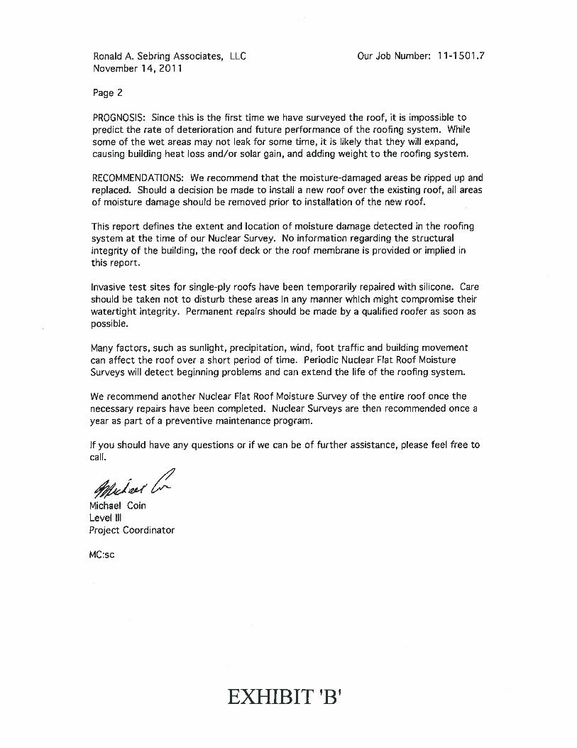
Ronald A. Sebring Associates, LLC Our Job Number: 11-1501.7November 14, 2011
Page 2
PROGNOSIS: Since this is the first time we have surveyed the roof, it is impossible topredict the rate of deterioration and future performance of the roofing system. Whilesome of the wet areas may not leak for some time, it is likely that they will expand,causing building heat loss and/or solar gain, and adding weight to the roofing system.
RECOMMENDATIONS: We recommend that the moisture-damaged areas be ripped up andreplaced. Should a decision be made to install a new roof over the existing roof, all areasof moisture damage should be removed prior to installation of the new roof.
This report defines the extent and location of moisture damage detected in the roofingsystem at the time of our Nuclear Survey. No information regarding the structuralintegrity of the building, the roof deck or the roof membrane is provided or implied inthis report.
Invasive test sites for single-ply roofs have been temporarily repaired with silicone. Careshould be taken not to disturb these areas in any manner which might compromise theirwatertight integrity. Permanent repairs should be made by a qualified roofer as soon aspossible.
Many factors, such as sunlight, precipitation, wind, foot traffic and building movementcan affect the roof over a short period of time. Periodic Nuclear Flat Roof MoistureSurveys will detect beginning problems and can extend the life of the roofing system.
We recommend another Nuclear Flat Roof Moisture Survey of the entire roof once thenecessary repairs have been completed. Nuclear Surveys are then recommended once ayear as part of a preventive maintenance program.
If you should have any questions or if we can be of further assistance, please feel free tocall.
Michael CoinLevel IllProject Coordinator
MC:sc
EXHIBIT ‘B’
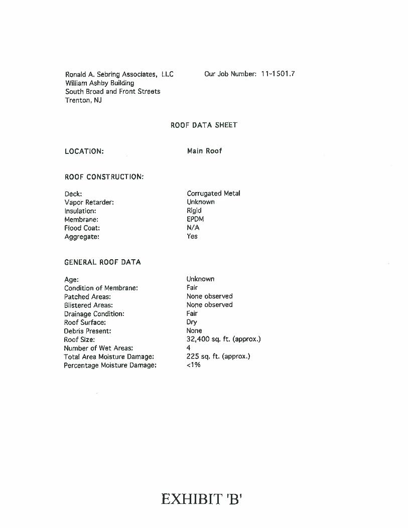
Ronald A. Sebring Associates, LLC Our Job Number: 11-1 501.7William Ashby BuildingSouth Broad and Front StreetsTrenton, NJ
ROOF DATA SKEET
LOCATION: Main Roof
ROOF CONSTRUCTION:
Deck: Corrugated MetalVapor Retarder: UnknownInsulation: RigidMembrane: EPDMFlood Coat: N/AAggregate: Yes
GENERAL ROOF DATA
Age: UnknownCondition of Membrane: FairPatched Areas: None observedBlistered Areas: None observedDrainage Condition: FairRoof Surface: DryDebris Present: NoneRoof Size: 32,400 sq. ft. (approx.)Number of Wet Areas: 4Total Area Moisture Damage: 225 sq. ft. (approx.)Percentage Moisture Damage: <1 %
EXHIBIT ‘B’
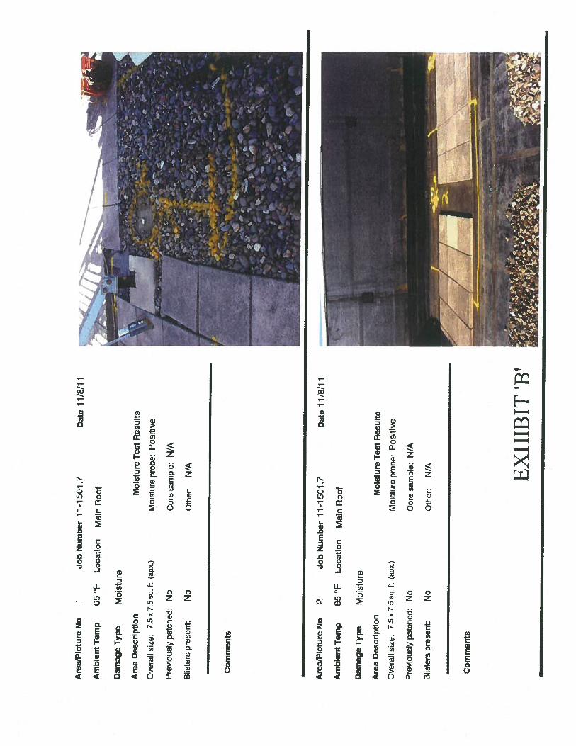
Are
a/P
ictu
reN
o1
Am
bien
tTem
p65°F
Dam
age
Typ
eM
oist
ure
Are
aD
escr
ipti
on
Ove
rall
size
:7.
5x
7.5
sq.
ft.(a
px.)
Pre
viou
sly
patc
hed:
No
Blis
ters
pres
ent:
No
Co
rnm
ents
Are
a/P
ictu
reN
o
Am
bien
tT
emp
Dam
age
Typ
eM
oist
ure
Are
aD
escr
ipti
on
Ove
rall
size
:7.
5x
7.5
sq.f
t.(a
px.)
Pre
viou
sly
patc
hed:
No
Blis
ters
pres
ent:
No
Co
mm
ents
Job
Nu
mb
er
11
-15
01
.7D
ate
11/8
/11
Loc
atio
nM
ain
Roo
t
Moi
stur
eT
est
Res
ult
s
Moi
stur
epr
obe:
Pos
itiv
e
Cor
esa
mpl
e:N
/A
Oth
er:
N/A
2Jo
bN
umbe
r11-1
501.7
65°F
Loc
atio
nM
ain
Roo
t
Dat
e11
/8/1
1
MoI
stur
eT
est
Res
ult
s
Moi
stur
epr
obe:
Pos
itiv
e
Cor
esa
mpl
e:N
/A
Oth
er:
N/A EX
HIB
IT‘B
’

Are
a/P
ictu
reN
o3
Am
bien
tT
emp
65°F
Dam
age
Ty
pe
Moi
stur
e
Are
aD
escr
ipti
on
Ove
rall
size
:7.5
x7.
5sq
.ft
(apx
.)
Pre
viou
sly
patc
hed:
No
Blis
ters
pres
ent:
No
Com
men
ts
Mois
ture
Tes
tR
esult
s
Moi
stur
epr
obe:
Pos
itiv
e
Cor
esa
mpl
e:N
/A
Oth
er:
N/A
Are
a/P
ictu
reN
o
Am
bie
nt
Tem
p
Dam
age
Ty
pe
Moi
stur
e
Are
aD
escr
ipti
on
Ove
rall
size
:7.
5x
7.5
sq.
ft.(a
px.)
Pre
viou
sly
patc
hed:
No
Blis
ters
pres
ent:
No
Co
mm
ents
Job
Num
ber
11-1
501.7
Dat
e1
1/8
/11
Loc
atio
nM
ain
Roo
f
4Jo
bN
umbe
r11-1
501.7
65°F
Loc
atio
nM
ain
Roo
f
Dat
e11/8
/11
Moi
stur
eT
est
Resu
lts
Moi
stur
epr
obe:
Pos
itiv
e
Cor
esa
mpl
e:N
/A
Oth
er:
N/A
EX
HIB
IT‘B
’
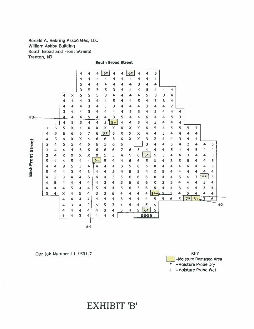
Ronald A. Sebring Assodates, LLCWilliam Ashby BuildingSouth Broad and Front StreetsTrenton, NJ
South Broad Street
4Li4 4Li44444444
5444444
____
3535344
4 X 6553444
444 344 5 44
444 345 344
344 34444 5
444 5443 5 4
4 5 ati14755 XXX XXX XX
4 5 6 6 6 7 6J6 X X
4 54 XX 466 6 XX
54 5 54665 66
3 4446 666 6 76
3 4 X X X X X 5 5 4 5
4 4 6
5 4 4 3 4 3j4 4 5 4 6
“ 4 3 5 6
4 5 44444343 6
4 X 4544 54436
34 X 4 5433 644
44444443 4
434355344
444443454
443 4444
45
444
344
45444
45334
54534
43 447
345444
46 4453
545444
X 6 54 5 5 5 7
X 4454444
X 3 344344
3 4 4 5 4 3 4 4 5
3 444544544
3 4 4 3 4 4 3
6 5 X 433 5445
66 X 4444445
54 X 5444444
6 6 X 4 4 5 4 3jj566 X 3344454
3 6 64434444
4 4 5 4 4 4
: : 6
5R16
KEYfj=Moisture Damaged Area
* =Moisture Probe Dry+ =Moisture Probe Wet
0?0J‘a
‘at2U
‘UILl
I DOOR
#4
Our Job Number 11-1501.7
#2
EXHIBIT ‘B’
APPENDIX “D”
• Construction Cost Estimates
o Replacement of Entire Roof with New EPDM fully AdheredSystem
o Replacement of Entire Roof with New EPDM Ballasted System
o Replacement of Entire Roof with New Built-up Asphalt System
EXHIBIT ‘B’

GENERAL REQUIREMENTS (DIVISION 1)BOND IL S.INSURANCE /LS.TEMPORARY TOILET IMONTHSAFETY AND PROTECTION COSTS IL SMOBILIZATION I DEMOBILIZATION /L.S.CRANE IMONTH
GENERAL REQUIREMENTS (DIVISION 1)
100 $0.001.00 $0004.00 $0.001.00 $1,500.001.00 $0001.00 $0.00
$11,250.00 $000 $11,250.00$35,000 00 $000 $35000.00
$180.00 $000 $720.00$5,000.00 $1,500.00 $5,000.00
$22,500.00 $0.00 $22,500.00$46,000.00 $0.00 $46,000.00
SITEWORK (DIVISION 2)DEMOLITION
INSULATION REMOVAL /B.F.CONCRETE PAVER REMOVAL 1SF.BALLAST ROCK REMOVAL VAC. IS F.SINGLE-PLY EPDM ROOF REMOVAL/S FWALL FLASHING REMOVAL /S.F.2X4 WOOD NAILERS / L.F.MISCELLANEOUS DEMOLITION /L.SCHUTE /L.F.RUBBISH HANDLING ICY.DUMPSTER /EACI-I
AREA ADJUSTMENT DMSION 2
107,640,00 $0.185,871.00 $0.82
23,920.00 $0 7123.920,00 $0.19
4,738.00 $0.3752800 $0.20
1.00 $2000.00110.00 $21.5045000 $2250
12.00 $0.00
4 40%
$0.28 $19,375.20 $30,139 20$1.25 $4,814.22 $7,338.75$1 09 $0.00 $26,072.80$0.29 $4,532.84 $6,936.80$0.56 $1,729.37 $2,653.28$020 $105.60 $105.60
$2,500.00 $2,000 00 $2,500.00$90.50 $2,365.00 $9,955.00$3450 $10,125.00 $15,525.00
$900.00 $0.00 $10,800 00
1.80% $1,982.08 $2,016.48
METALSMETAL DECKING REPLACEMENT/S.F.
AREA ADJUSTMENT DMSION 3
CARPENTRY2X4 WOOD NAILERS /M.B.F.
AREA ADJUSTMENT DMSION 6
WOOD AND PLASTICS (DIVISION 6)
3.33 $1,400.00 $2,900.00 $4,662.00 $9,657.00
23.90% 12.40% $1,114.22 $1,197.47
ROOF REPLACEMENTEPDM ROOFING FULLY ADHERED /Sq.EPDM FLASHINGS /S FEPDM FLASHING IRDLLEPDM PRIMER AND CLEANER /GALLONEPDM WALK PADS/EACHSEAM TAPE /EACH ROLLINSULATION ADHESIVE /CANEPDM ADHESIVE /CAN1.5” INSULATION IS.FTAPERED INSULATION 1/4” /B.F.METAL COUNTER- FLASHING /L F.METAL COPING REMOVE AND RESET IL.F.4” CANT/LFPIPE VENT FLASHING/EACHFLUE FLASHING/EACHREPLACE RAIL CURBS /EACHNEW PIPE PORTALS/EACHROOF DRAIN FLASHING /EACHCAULKING /L.F.
AREA ADJUSTMENT DIVISION 7
ThERMAL AND MOISTURE PROTECTION (DIVISION 7)
239.20 $52.502,400.00 $0.98
16.00 $5.2528.00 $0.00
1,080.00 $8.0048.00 $5.00
240.00 $0.00120.00 $0.00
23,920 00 $0.2471,760.00 $0.21
258.00 $2.00888.00 $8.95
2,800.00 $0.929.00 $20.001.00 $50.00
19.00 $50.001000 $75.0014.00 $85.00
2,632.00 $1.23
24.60%
$215.00 $12,558.00 $51,428.00$2.74 $2,352.00 $6,576.00
$169.25 $84.00 $2,708.00$30.00 $0.00 $84000$25.00 $8,640.00 $27,000.00$75.00 $240.00 $3,600.00$55.00 $0.00 $13,200.00$65.00 $0.00 $7,800.00
$1.13 $5,740.80 $27,029.60$0.93 $15069 60 $66736.80$580 $53148 $1,496.40
$11.20 $7,947.60 $9,945.60$1.75 $2,576.00 $4900.00
$50.00 $18000 $450.00$75.00 $50.00 $75.00
$125.00 $950.00 $2,375.00$350.00 $750.00 $3,500.00$125.00 $1,190.00 $1,750.00
$2.21 $3,237.36 $5,816.72
8.30% $15,275.82 $19,689.85
EXHIBIT ‘B’
ITEM
CONSTRUCTION COST ESTIMATE
ROOF REPLACEMENTWILLIAM ASHBY BUILDING
TRENTON NEW JERSEYEPDM Fully Adhered Roofing System
12127111
QUAN. UNIT AMOUNTLABOR TOTAL
TOTALLABOR TOTAL
METALS (DIVISION 5)
2000.00 $0.35 $2.57 $700.00 $5,140.00
7.20% -2.00% $50.40 ($102.80)
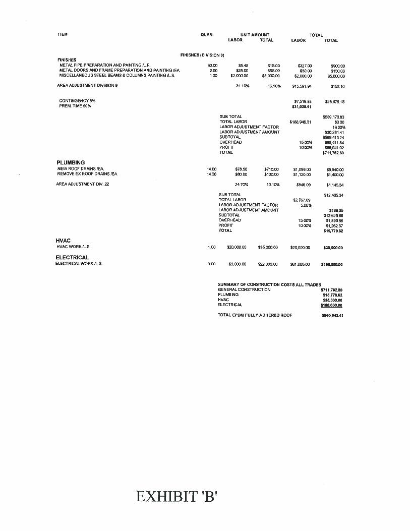
ITEM QUAN. UNIT AMOUNT TOTALLABOR TOTAL LABOR TOTAL
FINISHES (DIVISION 9)FINISHES
METAL PIPE PREPARATION AND PAINTING/LF. 60.00 $5.45 $15.00 $327.00 $900.00METAL DOORS AND FRAME PREPARATION AND PAINTING /EA. 2.00 $25.00 $65.00 $50.00 $130.00MISCELLANEOUS STEEL BEAMS & COLUMNS PAINTING /L.S. 1.00 $2,000.00 $5,000.00 $2,000.00 $5,000.00
AREA ADJUSTMENT OMSION 9 31.10% 16.90% $15,591.94 $152.10
CONTINGENCY 5% $7,519.88 $25,675.18PREM. TIME 50% $31,028.91
SUB TOTAL $539,178.53TOTAL LABOR $188,946.31 $0.00LABOR ADJUSTMENT FACTOR 1600%LABOR ADJUSTMENT AMOUNT $30,231.41SUBTOTAL $569,410.24OVERHEAD 15.00% $85,411.54PROFIT 10.00% $56,941.02TOTAL $711,762.80
PLUMBINGNEWROOFDRAINS/EA. 14.00 $78.50 $710.00 $1,099.00 $9,940.00REMOVEEXROOFDRAINSIEA 14.00 $80.00 $100.00 $112000 $1,400.00
AREAADJUSTMENTDF/. 22 24.70% 10.10% $548.09 $1,145.34
SUB TOTAL $12,485.34TOTAL LABOR $2,767.09LABOR ADJUSTMENT FACTOR 5.00%LABOR ADJUSTMENT AMOUNT $13835SUBTOTAL $12,623.69OVERHEAD 1500% $1,893.55PROFIT 10 00% $1,262 37TOTAL $15,779.62
HVACHVAC WORK /L.S. 1.00 $20,000.00 $35,000.00 $20,000.00 $35,000.00
ELECTRICALELECTRICAL WORK /L.S. 9 00 $9,000.00 $22,000.00 $81,000.00 $198,000.00
SUMMARY OF CONSTRUCTION COSTS ALL TRADESGENERAL CONSTRUCTION $711,762.80PLUMBING $15,779.62HVAC $35,000.00ELECTRICAL $198,000.00
TOTAL EPDM FULLY ADHERED ROOF $960,542.41
EXHIBIT ‘B’
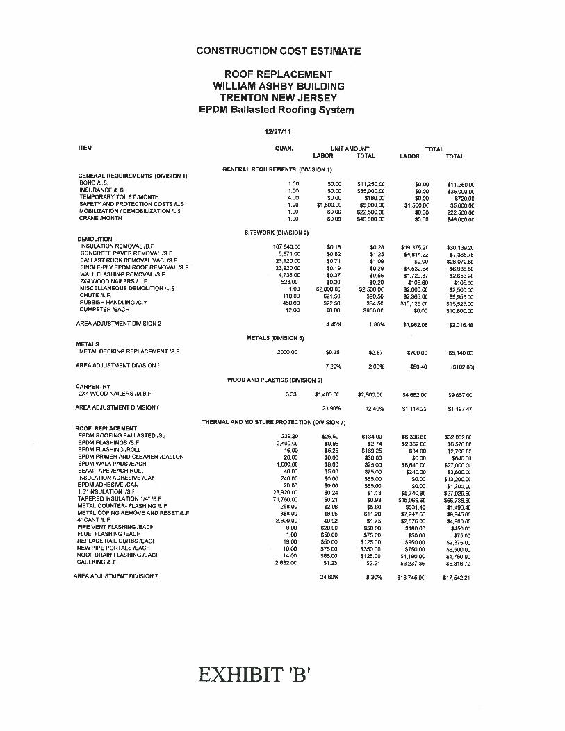
GENERAL REQUIREMENTS (DIVISION 1)BOND /LS.INSURANCE /L.S.TEMPORARY TOILET /MONTISAFETY AND PROTECTION COSTS /L.SMOBILIZATION I DEMOBILIZATION IL.0CRANE /MONTH
GENERAL REQUIREMENTS (DIVISION 1)
1.00 $0.001.00 $0.00400 $0.001.00 $1,500.OC1.00 $0.001.00 $0.00
$11,250.00 $0.00 $11250.00535,000CC $0.00 $35,000.0C
$180.00 $0.00 $720.00$5,000 DC $1,500.OC $5,000.00
$22,500.OC $0 00 $22,500.0C$46,000.OC $0.00 $46,000.OC
DEMOLITIONINSULATION REMOVAL /B.FCONCRETE PAVER REMOVAL/S.FBALLAST ROCK REMOVAL VAC /S.FSINGLE-PLY EPDM ROOF REMOVAL/S FWALL FLASHING REMOVAL /S.F2X4 WOOD NAILERS / L.FMISCELLANEOUS DEMOLITION /L.SCHUTE IL.F.RUBBISH HANDLING /C.YDUMPSTER /EACH
AREA ADJUSTMENT DIVISION 2
SITEWORI( (DIVISION 2)
107,640.OC $0.185871 DC $0.82
23920.OC $0.7123,920.00 $0.194,738 DC $0.37528.00 $0.20
1.00 $2,000.OC110.00 $21.50450.00 $22.50
12.00 $0.00
4.40%
$0.28 $19,375.2C $30,139,2C$1 25 $4,814.22 $7,338.7$1.09 $0.00 $26,072 80$0.29 $4,532.84 $6936 SC$056 $1,729.37 $2,653.26$0.20 $105.60 $105.60
$2,500.OC 52,000CC $2,500.00$90.50 $2365.OC $9,955.OC$3450 $10,125.OC $15.5250C
$900.00 $0 00 $10,800.0C
1.80% $1,962 08 $2,016.46
METALSMETAL DECKING REPLACEMENT/S.F
AREA ADJUSTMENT DIVISION
CARPENTRY2X4 WOOD NAILERS /M,B.F
AREA ADJUSTMENT DIVISION
WOOD AND PLASTICS (DIVISION 6)
3.33 $1 .400 DC $2,900,OC $4662 DC 89.657CC
23.90% 12.40% $1,114.22 $1,197.47
ROOF REPLACEMENTEPDM ROOFING BALLASTED /SqEPDM FLASHINGS /S.FEPDM FLASHING /ROLLEPDM PRIMER AND CLEANER /GALLONEPDM WALK PADS /EACHSEAM TAPE /EACH ROLLINSULATION ADHESIVE /CAFsEPDM ADHESIVE /CAI1 5’ INSULATION /S.FTAPERED INSULATION 1/4” IB.FMETAL COUNTER- FLASHING /L.FMETAL COPING REMOVE AND RESET/L.F4”CANT/LFPIPE VENT FLASHING /EACIFLUE FLASHING /EACHREPLACE RAIL CURBS lEAdNEW PIPE PORTALS /EACIHROOF DRAIN FLASHING /EACICAULKING /L.F.
AREA ADJUSTMENT DIVISION 7
ThERMAL AND MOISTURE PROTECTION (DIVISION 7)
239.20 826.502,400.OC $0.98
16.00 $5.2528.00 $0.00
1,080.OC $8.0048.00 $5.00
240.00 $0.0020.00 $0.00
23920CC $0.2471,760.00 $0.21
258.00 $2.00888.00 $8.95
2,800.0C $0.929.00 $20.001.90 $5000
19.00 $50.0010.00 $75.0014.00 $8500
2,632.OC $1.23
24.60%
$134.00 $6,338.80 $32,052.SC$2.74 $2,352 DC $6,576.OC
$169.25 $84.00 $2,708.OC$30.00 $0.00 $840.00$25.00 $8,640.OC 527,000CC$75.00 $240.00 $3,600.OC$55.00 $0.00 $13,200,OC$65.00 $0.00 $1,300.OC
$1 13 $5,740.8C $27.029.6C$0.93 $15,069.6C $66.736.8C$5.80 $531.48 $1,496.4C
$11.20 $7.947.BC $9,945.50$1.75 $2,576.OC $4,900.00
$50.00 $160.00 $450.00$75 00 $50.00 $75 00
$125.00 $950.00 $2,375.00$350.00 $750.00 $3,500 CC$125.00 81,190CC $1,750.00
$2.21 $3,237.38 $5,816.72
8.30% $13,745.9C $17,542.21
EXHIBIT ‘B’
CONSTRUCTION COST ESTIMATE
ROOF REPLACEMENTWILLIAM ASHBY BUILDING
TRENTON NEW JERSEYEPDM Ballasted Roofing System
12127/11
ITEM QUAN. UNIT AMOUNT TOTALLABOR TOTAL LABOR TOTAL
METALS (DIVISION 5)
2000.00 $0.35 $2.57 $700.00 $5,140.00
7 20% -2.00% $5040 ($102.80)

FINISHESMETAL PIPE PREPARATION AND PAINTING IL.FMETAL DOORS AND FRAME PREPARATION AND PAINTING /EPMISCELLANEOUS STEEL BEAMS & COLUMNS PAINTING /L.0
AREA ADJUSTMENT DIVISION 9
CONTINGENCY 5%PREM. TIME 50%
PLUMBINGNEW ROOF DRAINS /EAREMOVE EX ROOF DRAINS lEA
AREA ADJUSTMENT DIV. 22
QUAN. UNIT AMOIJNT TOTALLABOR TOTAL LABOR TOTAL
SUB TOTALTOTAL LABORLABOR ADJUSTMENT FACTORLABOR ADJUSTMENT AMOUNTSUBTOTALOVERHEADPROFITTOTAL
$12,485.34
$138.35$12,623.65
15.00% $1,893.5510.00% $1,262.37
$15,779.62
HVACHVAC WORK IL S
ELECTRICALELECTRICAL WORK /L.S
SUMMARY OF CONSTRUCTiON COSTS ALL TRADESGENERAL CONSTRUCTIONPLUMBINGHVACELECTRICAL
$672,633.66$15779.62$35,000.08
$1 98,000.08
TOTAL EPDM BALLASTED ROOF
EXHIBIT ‘B’
$921,413.29
ITEM
FINISHES (DIVISION 9)
60.00 $5.45 $15.00 $327.00 $900.002.00 $25.00 $65.00 $50.00 $130.001.00 $2,000.0C $5,000.00 $2,000.OC $5,000.OC
31.10% 16.90% $15116.14 $152.10
SUB TOTALTOTAL LABORLABOR ADJUSTMENT FACTORLABOR ADJUSTMENT AMOUNTSUBTOTALOVERHEADPROFITTOTAL
$7,108.62 $24,274.04$27,919.31
$509,754.84$177,200.54 $0.00
16.00%$28,352.06
$538,106.9215.00% $80,716.041000% $53,810.65
$672,633.66
14.00 $78.50 $710.00 $1,099.OC $9,940.OC14.00 $80.00 $100.OC $1,120.00 $1,400 00
24.70% 10.10% $548.09 $1,145.34
$2,767.095.00%
1 00 $20,000.00 $35,000.00 $20,000.00 $35,000.09
9.00 $9,000.OC $22,000.OC $81,000.00 $198,000.08
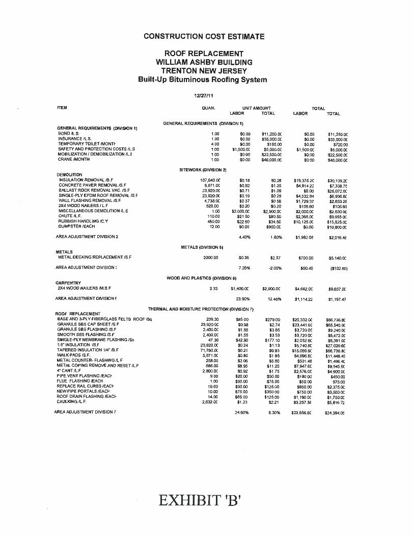
METALSMETAL DECKING REPLACEMENT/S.F
AREA ADJUSTMENT DIVISION
CARPENTRY2X4 WOOD NAILERS /M.B.F
AREA ADJUSTMENT DIVISION
METALS (DIVISION 5)
2000.00
WOOD AND PLASTICS (DIVISION 6)
$0.35 $2.57 $700.00 85,140CC
7,20% -2.00% $50.40 ($102.80)
3.33 $1.400.OC
23.90%
82.900CC $4,662.OC $9,657.00
12.40% $1,114.22 $1197.47
EXHIBIT ‘B’
CONSTRUCTION COST ESTIMATE
ROOF REPLACEMENTWILLIAM ASH BY BUILDING
TRENTON NEW JERSEYBuilt-Up Bituminous Roofing System
12/27111
QUAN. UNIT AMOUNTLABOR TOTAL
GENERAL REQUIREMENTS (DMSION 1)
1.00 $0.001.00 $0.004.00 $0.001.00 81,500CC1.00 $0.001 00 $0.00
SITEWORK (DIVISION 2)
107,640.OC $0.185871CC $0.82
23,920CC $07123,920CC $0.194,738CC $037
528.OC $0201 00 $2,000 CC
110.00 $21.50450.00 $22.50
12.00 $000
4.40%
TOTALITEM
GENERAL REQUIREMENTS (DIVISION 1)BOND /L.S.INSURANCE /L.S.TEMPORARY TOILET /MONTISAFETY AND PROTECTION COSTS/L.SMOBILIZATION? DEMOBILIZATION /L.5CRANE /MONTH
DEMOLITIONINSULATION REMOVAL/S.FCONCRETE PAVER REMOVAL /S.FBALLAST ROCK REMOVAL VAC. /S.FSINGLE-PLY EPDM ROOF REMOVAL /S.FWALL FLASHING REMOVAL/S F2X4 WOOD NAILERS / L.FMISCELLANEOUS DEMOLITION /L.SCHUTE IL.F.RUBBISH HANDLING /C.YDUMPSTER lEACH
AREA ADJUSTMENT DIVISION 2
LABOR TOTAL
$11.250.0C $0.00 $11 250.0C835,000CC $0.00 $35,000.OC
$180.00 $0.00 $720.0085,000CC si,soooc $5,000.OC
822,500CC $0 00 822,500CC$46,000.0C $0.00 $46,000.00
$0.28 $19,3752C $30,139.2C$1.25 $4814.22 $7,338.75$1.09 $0.00 $26072 8C$0.29 $4,532.84 $6,936 BC$0.55 $1729.37 $2653.26$0.20 $105.6C $105.60
$2,500.00 $2,000 DC $2,500 oc$90.50 $2.365.OC $9,955.OC$3450 810.125CC $15,5250C
$900.00 $0.00 $1 0,800CC
1.80% $1,982.08 $2,016.46
ThERMAL AND MOISTURE PROTECTION (DIVISION 7)ROOF REPLACEMENT
BASE AND 3-PLY FIBERGLASS FELTS ROOF /Sq 239.20 $85.00 $27900 820,332CC $66,736.8cGRANULE SBS CAP SHEET/S.F 23,920.OC $0.98 $2.74 $23,441.6c $65,540.8CGRANULE SBS FLASHING /S.F 2,400CC $1.55 $3.85 $3,720.0c 89,240CCSMOOTH SBS FLASHING/S.F 2,400.OC $1.55 $3.53 83,720CC $8,472.OCSINGLE-PLY MEMBRANE FLASHING /Sq 47.38 $42.90 $177.10 $2,032.6C 88,391CC1.5” INSULATION /S.F 23,920.OC $0.24 $1.13 $5,740.8C $27,029.6CTAPERED INSULATION 1/4” /B.F 71,760CC $0.21 $0.93 $15,069.6C $66,736.8CWALKPADS/S.F. 5,871CC $0.80 $1.95 $4,696.8C $11,448.45METALCOUNTER-FLASHING/L.F 258.00 $2.06 $580 $531.48 $1,496.4CMETAL COPING REMOVE AND RESET/L F 888.00 $8.95 $11.20 $7,947.6C $9,945.604” CANT/L.F 2.800CC $0.92 $1.75 82,576Cc $4.900.0cPIPE VENT FLASHING /EACI- 900 $2000 $60.00 $180.00 8450CCFLUE FLASHING/EACH 1.00 $50.00 875.00 $50.00 $75.00REPLACE RAIL CURBS /EACI- 19.00 $50.00 5125CC $950.OC $2,375.00NEW PIPE PORTALS lEAd” 1000 $75.00 $35000 $75000 $3,500.00ROOF DRAIN FLASHING/EACI- 1400 $85.00 $125.OC 81,190CC 81,750CCCAULKING/L.F 2,632CC $1.23 $2.21 $3,237.36 $5,816.72
AREA ADJUSTMENT DIVISION 7 24.60% 8.30% 823,656.80 $24,394.05
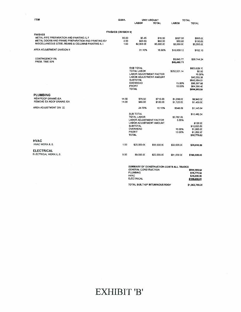
FINISHESMETAL PIPE PREPARATION AND PAINTING /L.FMETAL DOORS AND FRAME PREPARATION AND PAINTING /EPMISCELLANEOUS STEEL BEAMS & COLUMNS PAINTING IL.5
AREA ADJUSTMENT DIVISION 9
CONTINGENCY 5%PREM. TIME 50°,4
FINISHES (DIVISION 9)
60.00 $5.45 $15.00 $327.002.00 $25.00 $65.00 $50.001.00 $2,000.OC $5,000.00 $2,000.OC
31.10% 16.90% $19,659.10
$900.00$130.00
$5,000.OC
$152.10
$9,845.73 $28,744.24$45,460.71
HVAC WORK/L.S.
ELECTRICALELECTRICAL WORK /L.S.
SUB TOTALTOTAL LABORLABOR ADJUSTMENT FACTORLABOR ADJUSTMENT AMOUNTSUBTOTALOVERHEADPROFITTOTAL
14.00 $78.5014.00 $80.00
24.70%
SUB TOTALTOTAL LABORLABOR ADJUSTMENT FACTORLABOR ADJUSTMENT AMOUNTSUBTOTALOVERHEADPROFITTOTAL
$603,629.12$252,221.14 $0.00
16.00%$40,355.38
$643,984.5115.00% $96,597.6810.00% $64,398.45
$804,980.64
$9,940 OC$1 ,400.OC
$1145.34
$12,485.34
$138.35$12,623.60
15.00% $1,893.5510.00% $1,262.37
$16,779.62
SUMMARY OF CONSTRUCTION COSTS ALL TRADESGENERAL CONSTRUCTIONPLUMBINGHVACELECTRICAL
________
TOTAL BUILT-UP BITUMINOUS ROOF $1,053,760.2E
ITEM QUAN. UNIT AMOUNTLABOR TOTAL
TOTALLABOR TOTAL
PLUMBINGNEW ROOF DRAINS /EA.REMOVE EX ROOF DRAINS /EA
AREA ADJUSTMENT DIV. 22
HVAC
$710.00 $1,099.OC$100.00 $1,120.00
10.10% $548.09
$2,767.095.00%
1.00 $20,000.OC $35,000.OC $20,000.OC $35,000.00
9.00 $9,000.OC $22,000.00 $81,000.OC $198,000.00
$804,980.64$1 5,779.62$35,000.00
$198,000.00
EXHIBIT ‘B’