programme area: smart systems and heat project: enabling
TRANSCRIPT

Title:
Disclaimer:
The key objective was to identify a short-list of technology development opportunities for specific technologies
which are likely to have a role in smart heating systems that, under certain scenarios, have the potential to make
a significant contribution to reducing national carbon emissions. To provide a comprehensive assessment of the
issues associated with implementing new, low carbon heating systems, it is also necessary to consider the
impact of technology selection on the wider energy system and the influence that the nature of the local area
might have on technology choice. To provide a framework for this analysis, the Consortium has developed the
concept of Host Space Environments (HSEs), which are archetypes of local areas, typical in terms of mix and
density of buildings, to real towns, cities and rural settlements. The report was initially published in July 2013.
Some details and analysis may be out of date with current thinking.
Context:This project identified gaps in the range of potential smart systems technologies to accelerate the development
of component technologies which are required for any successful deployment and operation of a future smart
energy system. This £500k project was announced in February 2013 and was delivered by a consortium of
partners that includes Hitachi Europe, EDF Energy, Element Energy, David Vincent & Associates and Imperial
Consultants.
The Energy Technologies Institute is making this document available to use under the Energy Technologies Institute Open Licence for
Materials. Please refer to the Energy Technologies Institute website for the terms and conditions of this licence. The Information is licensed
‘as is’ and the Energy Technologies Institute excludes all representations, warranties, obligations and liabilities in relation to the Information
to the maximum extent permitted by law. The Energy Technologies Institute is not liable for any errors or omissions in the Information and
shall not be liable for any loss, injury or damage of any kind caused by its use. This exclusion of liability includes, but is not limited to, any
direct, indirect, special, incidental, consequential, punitive, or exemplary damages in each case such as loss of revenue, data, anticipated
profits, and lost business. The Energy Technologies Institute does not guarantee the continued supply of the Information. Notwithstanding
any statement to the contrary contained on the face of this document, the Energy Technologies Institute confirms that the authors of the
document have consented to its publication by the Energy Technologies Institute.
Programme Area: Smart Systems and Heat
Project: Enabling Technologies
Identifying a short-list of technologies for potential engagement by the
ETI
Abstract:

Smart Systems and Heat – Work Area 1:
Enabling Technologies
Task 3, Step 1 – Identifying a short-list of technologies for
potential engagement by the ETI
Final Report
19th July 2013

2
Contents 1 Executive Summary ......................................................................................................................... 4
2 Introduction .................................................................................................................................... 7
3 Introduction to the HSE concept ..................................................................................................... 9
3.1 HSEs and House types ............................................................................................................. 9
3.2 Factors affecting heating technology suitability ................................................................... 10
3.3 Summary of the six HSEs ....................................................................................................... 12
3.4 Problem statement ............................................................................................................... 13
3.5 Representation of the overall dwelling stock ....................................................................... 17
4 Gap analysis of technology packages ............................................................................................ 19
4.1 Technology deployment scenarios ....................................................................................... 19
4.2 Building-level technology packages ...................................................................................... 21
4.2.1 Cross-cutting issues and enablers ................................................................................. 31
4.3 Host Space Environment level assessment ........................................................................... 31
4.3.1 Cost analysis .................................................................................................................. 32
4.3.2 Grid reinforcement costs .............................................................................................. 36
4.4 Carbon emissions impact ...................................................................................................... 40
4.5 Packages of solutions ............................................................................................................ 43
5 Short-list of technologies / systems and rationale ....................................................................... 46
6 Criteria and proposed priority technologies / systems ................................................................ 49
7 Next steps ..................................................................................................................................... 52
8 Appendices .................................................................................................................................... 53
Appendix A – Host Space Environments ............................................................................................... 53
Appendix B – Technology deployment scenarios ................................................................................. 62
The detail of the scenarios used for the analysis is presented in the table below. .............................. 62
Appendix C – Key enabling technologies .............................................................................................. 63
C2.1 Building level control strategies: ....................................................................................... 68
C2.2 HSE level control strategies: ............................................................................................. 69
Appendix D – Network Solutions .......................................................................................................... 71
Appendix E – Technology gap analysis .................................................................................................. 76
E1. Technology selection criteria ...................................................................................................... 76
E2. Technology analysis .................................................................................................................... 77

3
Appendix F – Cost and Carbon emissions assessment ......................................................................... 95
F.1 – Capital cost estimates .............................................................................................................. 97
Appendix G – Scoring the short-list against the proposed criteria ....................................................... 99

4
1 Executive Summary
The Task objective
Task 3 Step 1 of WA1 was set up following discussions with the ETI to address the revised objective
set by the ETI: “to identify (through the identification of “gaps”) a small number of short term
involvement / engagement opportunities for the ETI – these relate to technologies / systems that are
likely to be included in a smart energy and heat system that can be made more effective through ETI
involvement”.
The scope and deliverables for the Task were set out in Variation Order 005.
The work on this Task was carried out between 18 April and 28 June 2013.
Approach
The Consortium approach to this Task was to:
(i) from general principles, create six Host Space Environments (HSEs) representative of at least
75% of the national housing stock in rural, suburban and urban settings. These HSEs serve as realistic
“base cases” against which the carbon savings performance of selected technology packages was
assessed and gaps identified.
(ii) devise technology packages appropriate to each dwelling type/location, after the
identification of particular technological problems associated with each HSE, comprising best
available and promising emerging technologies – treated as systems of interacting technologies.
Semi-quantitative methods (based on standard public domain software) were used to estimate the
impacts of these packages on carbon savings, costs, and on the networks supplying the HSEs.
(iii) produce a shortlist of technologies / systems that could result in a material reduction in
carbon emissions if the identified gaps were addressed and the technologies were deployed at scale
(iv) devise and apply selection criteria (aligned to the Consortium’s understanding of the ETI’s
needs); and produce a list of three priority technologies which would justify further consideration by
the ETI.
(v) summarise next steps.
In considering the nature of the above “gaps”, the Consortium is aware that they are characterised
by a range of technical, systems and non-technical factors. However, at ETI’s request, the
Consortium has limited its consideration of “gaps” to a purely technology / engineering perspective.

5
Technology shortlist
The following 15 technologies/systems were identified for shortlisting:
Heat distribution Fan-assisted radiators
Heat source
ASHP
Hybrid ASHP
Fuel cell mCHP
Storage HDTS / PCM
Monitoring & control Sensors / actuators
HEMS gateway / HAN
Heat network Low Temperature district heating network
Electricity distribution
Low Voltage control
D-FACTS (Distributed Flexible AC Transmission System)
DSR / thermal storage
Distributed generation
Community-scale CHP (biomass / biogas)
Community-scale energy from waste
Service level Cloud management Service
Energy Management Service
In the Consortium’s view, these technologies, as part of well designed, properly installed,
commissioned and managed heating systems, have the potential to deliver significant carbon savings
(a full set of assumptions is included in Appendix F), whilst at the same time minimising adverse
impacts on local networks (in respect of electric heating systems).
Priority technologies recommended for further investigation
At the request of the ETI, the Consortium devised for the ETI’s consideration a set of criteria for
selecting a limited number of priority technologies / systems for further investigation. On the basis
of these criteria and the analysis carried out to date, the following technologies are recommended
for further investigation by the ETI:
• Community scale biomass / biogas CHP
• LV Voltage control technologies
• Energy Management Services and advanced network controls systems.
Technical considerations would need to include, in addition to technology specific factors, systems
design (where “system” includes building fabric, controls, management, storage, heat generator,
heat emitters, etc.), optimisation and packaging. Non-technical factors would also need to be
considered including: supply chain coordination, installer competency, sale/lease and energy
services models, finance packages and system (as oppose to product) efficacy guarantees, etc.
In addition to the technologies identified above, assessment of the short-listed technologies on the
basis of the proposed criteria also highlights hybrid ASHP, High Density Thermal Storage (HDTS) and
HEMS / HAN as high priority technologies. These technologies were pre-selected by the ETI for
assessment in Task 5a. The analysis undertaken has validated the pre-selection of these

6
technologies, which in the Consortium’s view merit further consideration (beyond the scope of the
Task 5a assessment).

7
2 Introduction
The key objective of WA1 Task 3 was to identify a short-list of technology development
opportunities for specific technologies which are likely to have a role in smart heating systems that,
under certain scenarios, have the potential to make a significant contribution to reducing national
carbon emissions. The development opportunities have, at the ETI’s request, been considered from
the technology / engineering standpoint only. This short-list has been drawn up on the basis of the
Consortium’s research and analysis. It is presented for the ETI’s consideration and, we understand,
more detailed investigation. The aim of this process is to identify technology development
opportunities that would contribute to addressing the identified technical gaps and that might also
present commercial opportunities for ETI engagement. As requested therefore, we have, as part of
this study, proposed a set of criteria for ETI’s consideration. However, identifying these specific
development opportunities is beyond the scope of the Task 3 Step 1 study.
To identify the short-list of technologies, we have considered how technologies are combined into
smart heating systems and the issues associated with integrating these systems into buildings.
Through this analysis, we have sought to identify the barriers to widespread deployment of these
technologies and the technology gaps that need to be addressed. While the focus of this analysis is
the technologies and systems, we recognised that many of the most significant barriers are non-
technical and include factors such as costs, supply-side capacity, business models and agents, and
consumer perception and behaviour. Drawing on the knowledge of the Consortium, we have
attempted to capture these non-technical barriers and gaps at a high level. Further investigations
would be required to characterise the gaps at a level of detail consistent with the due diligence
required to understand and reduce the commercial risk associated with any investments or activities
the ETI decide to carry out.
To provide a comprehensive assessment of the issues associated with implementing new, low
carbon heating systems, it is also necessary to consider the impact of technology selection on the
wider energy system and the influence that the nature of the local area might have on technology
choice. To provide a framework for this analysis, we have developed the concept of Host Space
Environments (HSEs), which are archetypes of local areas, typical in terms of mix and density of
buildings, to real towns, cities and rural settlements. We have constructed from general principles
and publicly available data six specific HSEs for the ETI. The form and construction of the HSEs is
described in the following section.
This report presents the findings of the technology gap analysis and identifies the short-list of
technologies and proposed criteria for further down-selection. The report is structured as a concise
summary report and a detailed set of appendices, which provide further detail on the approach and
on the analysis of particular component technologies and systems. The summary report is
structured as follows:
• Section 3 provides an introduction to the HSE concept and the specific set of HSEs used in
this work.

8
• Section 4 contains the technology gap analysis at the building level and assessment of
impacts of technology deployment at the wider HSE level, particularly in terms of costs and
carbon saving.
• Section 5 presents the short-list of technologies and brief rationale for their inclusion.
• Section 6 provides the proposed criteria for further down-selection and the Consortium view
on priority technologies for further investigation.
• Section 7 presents proposals for structuring further work.

9
3 Introduction to the HSE concept
As part of the work in Task 3, Step 1 the Consortium developed the concept of Host Space
Environments (HSEs) from general principles. This was done to ensure that we identified technology
packages appropriate for use in a range of typical dwellings and locations.
HSEs are virtual constructs of groups of dwellings (and other buildings where appropriate), designed
to be representative of the UK housing stock in specific types of locations. They are characterised
according to a range of parameters to form the “base case” upon which the impact (including energy
and carbon savings, network impacts, etc.) of different existing and emerging technology packages
can be assessed. Depending on the range of parameters, HSEs can be made as coarse grain / simple
or as fine grain/ sophisticated as is required or can be accommodated within given time and budget
envelopes for investigation. The granularity can range from a grouping of house types according to
certain parameters (built form, location, etc.) to GIS mapping / postcode representation of actual
districts in real cities and detailed consideration of occupancy factors, heat networks, etc. They can
be limited to considering heat provision or can be made more sophisticated to include consideration
of, for example, export of solar generated electricity, electricity storage, etc. Within the available
budget and time envelopes, the Consortium has created the six HSEs for the ETI from published data
and with sufficient granularity to enable reasonable and robust conclusions to be drawn about the
performance of technology packages and the identification of technology and system gaps for
further assessment. In any future pieces of work, the HSEs could be designed for and used at
increasing degrees of granularity and sophistication to address wider issues and increasing
complexity.
The HSE granularity used in Step 1 provided a sufficient basis on which to assess technology
packages, identify technology gaps and make recommendations to the ETI on which technology
areas would be worthwhile assessing further for possible ETI engagement. Further work beyond Step
1 would consider the carbon performance achievable with different technology packages,
aggregated over the housing stock, in relation to a given position on a given decarbonisation
trajectory. This assessment of performance at scale is needed to confirm whether incremental
improvements of currently know and emerging technologies will be sufficient to achieve the carbon
savings necessary; or, if not, what kind of disruptive technologies will be needed.
The following section sets out the six HSEs developed by the Consortium for this task.
3.1 HSEs and House types
For the purposes of this Task, the national housing stock was categorised into six generic and typical
HSE settings as follows:
Rural village
Market town
Suburban (without a centre)
Suburban (with a centre)

10
Urban (without a centre)
Urban (with a centre).
The six HSEs have been constructed to be representative of over 75% of the national housing stock.
The house types in each HSE are also representative of the stock which we would expect to find in
specific locations. Thus, for example, the urban HSEs would contain more flats and terraced
dwellings than the rural HSEs where there are more detached houses. Using the standard source
literature (e.g. the English House Condition Survey1, neighbourhood statistics2), the actual dwelling
types and their respective proportions, conditions and densities in each of the six HSEs can be
reliably established. The housing stock has been classified into 12 house types, each of which is
described by the following characteristics:
main heating fuel (gas, electricity)
dwelling type (detached, semi-detached, terraced, flats)
standard of energy efficiency (good, poor)
wall construction type (cavity wall insulation, unfilled cavities and solid wall).
3.2 Factors affecting heating technology suitability
The nature of a building’s construction, its usage and occupancy patterns and preferences can have
implications for the selection of heating systems. The mix of building types, density of buildings and
features of the local environment can also influence choice of heating system and can be assessed
within the framework of the HSEs. Factors that have been taken into account include:
number of buildings and mix of building types
fabric performance and thermal mass of buildings
heat load density and demand profile
impact of heating technologies on the local distribution network (and wider system impacts)
space availability (e.g. domestic gardens and surrounding green space).
There are a number of other factors that are too location specific to form part of a limited set of
generalised HSEs but that can be important influences on heating system selection and design for a
particular area. These factors include:
proximity to large heat users
availability of waste heat
access to mains gas
mix of tenure type and socio-economic characteristics of an area
availability of renewable resources (e.g. wind, solar, biomass etc.)
1 English Housing Condition Survey, Communities and Local Government, 2012,
https://www.gov.uk/government/organisations/department-for-communities-and-local-government/series/english-housing-survey 2 http://www.neighbourhood.statistics.gov.uk

11
tolerance to other environmental impacts, such as noise, visual amenity, traffic (e.g. fuel
deliveries), etc.
While not part of the definition of the HSEs, the impact of these factors can be considered as
sensitivities.
Technologies, and the technology packages in which they operate, are parts of complex systems
(within buildings, between buildings, and the networks serving buildings). Buildings with different
technology packages and occupancies will have different energy / heat demand profiles. (However,
at the level of granularity selected for this work, standard occupancy patterns were applied as this
was appropriate and sufficient for this level of investigation). The way in which these different
demand profiles sum and then interact with local supply networks can have significant impacts that
need to be addressed and managed. HSEs can help us understand these impacts in the rural,
suburban and urban settings. The proportions of residential and non-domestic buildings therefore
need to be considered for each HSE. The methodology used to assess the number of non-domestic
connections within each of the HSEs is described in Appendix A – Host Space Environments.
Different technology packages (whether individual heating or community heating based; with or
without storage) will have different impacts on demand profiles and hence the local energy supply
networks. The Consortium has carried out a semi-quantitative analysis of impacts in order to give an
indication of where technology development (or help with early deployment via trials for example)
would be required.
The Consortium recognises that the cost of technology packages will be an important factor so far as
take-up is concerned. However, HSEs are not, in their simple form capable of incorporating and
utilising cost data. The cost implications of technology packages have therefore been estimated
separately. For existing technologies (e.g. fabric insulation, conventional air source heat pumps, etc.)
cost data exists. The Consortium has used this information to assess the cost implications of
particular technology packages. However, cost per se, has not been the arbiter of plausibility for
designing technology packages. For new and emerging technologies, the Consortium has used an
indicative cost figure (or range, if estimates exist), recognising that these figures may well change
over time (e.g. if manufacture increases and / or sales / leasing become a significant share of the
market, costs will reduce).

12
3.3 Summary of the six HSEs
The six HSEs developed for this study are summarised in the table below. Further detail on the six HSEs and the standard building types within the
HSEs is provided in the appendices (Appendix A – Host Space Environments).
Table 1. Summary of the six Host Space Environments
Community Type
Predominant
dwelling type
Non-dom
/resi ratio Garden
area Description
Rural Village Detached, semi Low -
medium High
Small settlements of dwellings and local amenities surrounded by agricultural land
or other green space.
Market Town Detached, semi,
terrace, flats Medium Medium
Larger communities with town centre. Rural in nature, surrounded by agricultural /
green space.
Suburban
residential
Semi, Terraced,
detached Low Medium
Typical edge of town housing estates. Homes have gardens but limited other green
space. Non-domestic area limited to small shops, pubs, schools.
Suburban with
local centre Semi and terraced Medium Medium
Similar housing density to suburban residential but in proximity to a local centre,
including larger retail, leisure and office uses.
Urban
(residential)
Terraces, flats
(converted and
purpose-built)
Low-medium Low Inner-city residential – terraced houses and flats. High built density with green
space limited to parks / allotments.
Urban centre Flats, Terraces Medium -
high Low
High density flats (purpose built and conversions) and terraced housing. Diverse
non-domestic uses, including commercial offices, large retail, leisure, pubs,
restaurants etc.

13
3.4 Problem statement
The table below provides a summary of the problem statements relevant to each Host Space Environment, both at the building and network /
district heating level. These problem statements were derived following discussions with the ETI (on 27 June). They have been drawn up on the
basis of the Consortium’s understanding of these discussions, recognising that the level of discussion did not allow a detailed definition to be
finalised. At the ETI’s request, they are derived from a technology / engineering perspective.
The general problem statement can be summarised as follows. Occupants of dwellings want affordable, responsive heating to the standard and at
the times they choose. Currently available systems provide what occupants want but at too high a carbon footprint to be consistent with national
decarbonisation goals for 2050. Very low carbon footprint heating* will be required across the UK’s housing stock in order to achieve carbon savings
consistent with decarbonisation trajectories. Current market penetration of low carbon heating systems is minute, compared with the national
stock of gas fired central heating systems. They are very expensive (at least three times the cost of mature gas-fired systems), disruptive and
complex. High cost, disruption to occupants, poor supply chain competency and complexity are the principal barriers which need to be overcome in
order to make a robust start on the heat decarbonisation challenge. Achieving these decarbonisation goals will require different
technological/systems solutions to be designed and implemented. Factors which would need to be considered include: location, occupant
behaviours and preferences, standard of energy efficiency and fabric insulation, housing density, commercially available products, or yet to be
developed technologies, etc. Some technological solutions will have impacts within HSEs and on networks serving HSEs (eg local electricity
distribution systems). Different house types and settings (as described by the six HSEs) will present different opportunities and challenges in respect
of the general problem statement. The key specific factors for each HSE and house types are given below.
*(The scope of this Task did not include cooling requirements. However, the Consortium is aware that summer time overheating is already
becoming a problem for some newer house designs in the UK. In any further consideration of technologies for space heating in the context of the
Smart Systems and Heat Programme, the Consortium recommends that the space cooling challenge should receive appropriate attention so that in
finding and implementing low carbon heating solutions and demand reduction measures, the cooling needs of occupants are not exacerbated.)

14
HSE Technology suitability – building level
Network-level implications
1 Village • Off-gas dwellings, although representing a small percentage of the stock, are most likely to be found within this HSE. This limits certain technology choices, although the higher cost incumbent fuel (e.g. heating oil) can favour uptake of low carbon technologies in these areas (e.g. heat pumps).
• This HSE could be favourable for biomass boilers uptake, given the predominance of larger dwellings with adequate space. Local availability of stock and fuel delivery, may restrict their uptake
• Communications might be constrained in remote rural areas, limiting some demand response and active network management options.
• Scenarios involving a high level of district heating penetration are less likely to be applicable
• Potential high impact of electricity heating technologies (e.g. ASHPs) on the local distribution network, given the reduced number of dwellings in the HSE (200 dwellings) if DSR/ LV control is not implemented. In that case, high grid reinforcement costs would arise
2 Market town
• Although this HSE could be favourable for biomass boilers uptake, given the predominance of big dwellings, local availability of stock and fuel delivery, might restrict their uptake
• Scenarios involving a high level of district heating penetration are less likely to be applicable (unless there are particular location specific factors, such as reliable long-term availability of waste heat from industrial / commercial development, that can improve the economics of district heating).
• Potential high impact of electricity heating technologies (e.g. ASHPs) on the local distribution network, given the reduced number of dwellings in the HSE (200 dwellings) if DSR/ LV control is not implemented. In that case, very high grid reinforcement costs would arise
3 Suburban residential
• Noise concerns in densely constructed areas for ASHPs • The fact that >15% of the HSE is comprises poorly insulated semi-
detached houses and terraces might hinder ASHPs uptake, given the additional insulation capital costs required for a successful ASHP installation. There is a prevalence of terraced houses in this HSE; ~50% of the poorly insulated terraces in the UK have solid wall insulation, adds to this fact
• Heat density is likely to be low for district heating (relatively low density housing and lack of non-domestic buildings).
• New generations of district heating networks (e.g. low temperature heat network) could be applied in this HSE. Particularly suitable for new build housing developments.
15
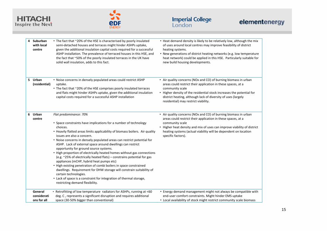
4 Suburban with local centre
• The fact that ~20% of the HSE is characterised by poorly insulated semi-detached houses and terraces might hinder ASHPs uptake, given the additional insulation capital costs required for a successful ASHP installation. The prevalence of terraced houses in this HSE, and the fact that ~50% of the poorly insulated terraces in the UK have solid wall insulation, adds to this fact.
• Heat demand density is likely to be relatively low, although the mix of uses around local centres may improve feasibility of district heating systems.
• New generations of district heating networks (e.g. low temperature heat network) could be applied in this HSE. Particularly suitable for new build housing developments.
5 Urban (residential)
• Noise concerns in densely populated areas could restrict ASHP uptake.
• The fact that ~20% of the HSE comprises poorly insulated terraces and flats might hinder ASHPs uptake, given the additional insulation capital costs required for a successful ASHP installation
• Air quality concerns (NOx and CO) of burning biomass in urban areas could restrict their application in these spaces, at a community scale
• Higher density of the residential stock increases the potential for district heating, although lack of diversity of uses (largely residential) may restrict viability.
6 Urban centre
Flat predominance: 70% • Space constraints have implications for a number of technology
choices. • Heavily flatted areas limits applicability of biomass boilers. Air quality
issues are also a concern. • Noise concerns in densely populated areas can restrict potential for
ASHP. Lack of external space around dwellings can restrict opportunity for ground source systems.
• High proportion of electrically heated homes without gas connections (e.g. ~25% of electrically heated flats) – constrains potential for gas appliances (mCHP, hybrid heat pumps etc)
• High existing penetration of combi boilers in space constrained dwellings. Requirement for DHW storage will constrain suitability of certain technologies.
• Lack of space is a constraint for integration of thermal storage, restricting demand flexibility.
• Air quality concerns (NOx and CO) of burning biomass in urban areas could restrict their application in these spaces, at a community scale
• Higher heat density and mix of uses can improve viability of district heating systems (actual viability will be dependent on location specific factors).
General considerations for all
• Retrofitting of low temperature radiators for ASHPs, running at <60 deg. C , represents a significant disruption and requires additional space (30-50% bigger than conventional)
• Energy demand management might not always be compatible with end-user comfort constraints. Might hinder EMS uptake
• Local availability of stock might restrict community scale biomass

16
HSEs • Stirling Engine (SE) mCHP systems, given their high heat to power ratios and the power capacities currently available , could be better suited to higher thermal demand dwellings, predominant in suburban and rural areas
• Local availability of fuel stock might restrict biomass boiler application
CHP application • There are a number of other factors that are too location specific to
form part of a limited set of generalised HSEs but that be important influences on heating system selection and design for a particular area. These factors include: - Proximity to very large heat users - Availability of waste heat - Access to mains gas - Mix of tenancy and socio-economic characteristics of an area - Availability of renewable resources (e.g. wind, solar, biomass etc.)

17
3.5 Representation of the overall dwelling stock
The intention of the HSEs is to represent a large proportion of the housing stock using a limited
number of typical area descriptions. As a result, the HSEs are necessarily highly generalised, such
that each HSE is broadly representative of a large proportion of the housing stock. One metric that
can be used to map the HSEs onto the stock in order to make a high-level assessment of how much
of the stock each HSE can be said to represent is the residential area fraction, i.e. the fraction of land
area in the local area that is used for domestic buildings. The distribution of the GB building stock by
residential area fraction of the local community (census ward level) is shown in the chart below. The
range of residential area fraction that is typical of each HSE is shown on the chart.
Figure 1, Cumulative frequency of GB dwelling stock by the residential area fraction of the local area (census ward level)
On the basis of the segmentation of the stock between the HSEs shown above (based on matching
the typical residential fraction of the HSEs to census ward level data on the stock), it is possible to
derive a rough order of magnitude estimate for the amount of the stock represented by each HSE /
dwelling type combination. This disaggregation of the stock by HSE and house type is tabulated
below.
This table provides an indication of the overall amount of the stock that the various problem
statements discussed above are applicable to and also the extent to which technology packages that
are well-suited to a particular HSE are applicable to the stock (see Section 4.5)
0
0.2
0.4
0.6
0.8
1
1.2
00
.01
0.0
20
.03
0.0
40
.05
0.0
60
.07
0.0
80
.09
0.1
0.1
10
.12
0.13
0.1
40
.15
0.1
60
.17
0.1
80
.19
0.2
0.2
10
.22
0.2
30
.24
0.2
50
.26
0.27
0.2
80
.29
0.3
Frac
tio
n o
f th
e h
ou
sin
g st
ock
Residential area fraction
Cumulative distribution of the dwelling stock by residential area fraction of the local areaHSE 1
HSE
2
HSE
3 & 4
HSE
5
HSE 6

18
Table 2, Approximate disaggregation of the dwelling stock between the HSEs and broad house type descriptions
HSE Detached Semi Terrace Flat TOTAL
1 8% 6% 4% 0% 18%
2 8% 5% 6% 5% 23%
3 3% 10% 7% 0% 19%
4 0% 12% 8% 0% 20%
5 0% 0% 10% 2% 12%
6 0% 0% 2% 6% 8%
TOTAL 19% 32% 36% 13% 100%

19
4 Gap analysis of technology packages
4.1 Technology deployment scenarios
The HSEs provide a framework for assessment of heating technologies and packages of technologies
(systems) that could provide significant carbon reduction if deployed at scale. The HSE framework is
used to assess the issues associated with integrating these technologies and systems into buildings
and wider local areas and the impact that their deployment might have in terms of carbon emissions
reduction. On this basis, we identified a priority list of technologies that appeared to be promising in
terms of future low carbon heating systems, fit for various building and area types. We also
identified the main barriers to the deployment of these priority technologies and the gaps, both
technical and non-technical, that would need to be addressed.
The technology packages or systems are made up from a set of components that were categorised
as follows:
These technology packages were initially assessed at the building level. We then considered what
the impact of the heating system selection is at the HSE level, particularly in terms of the impact of
technology deployment on the electricity distribution network and also the potential requirement of
controls and active management infrastructure upstream of the individual buildings. Through the
assessment at the HSE level, we also considered whether the characteristics of particular area types
lead to consideration of alternative heating system options, such as district heating. We also took
into account that, generally speaking, the standard of thermal insulation across the nation’s stock is
in need of significant improvement and that in order for technology packages to be most effective,
they would therefore have to include optimum levels of thermal insulation on each building element
consistent with practical constraints.
In addition to the assessment of barriers to deployment of systems and the associated gaps, we have
also quantitatively estimated the cost implications of particular systems and CO2 emissions reduction
potential. We have taken a view on the level of penetration of the technology packages in order to
arrive at our cost estimates.
Modelling the uptake of technologies or systems has not been undertaken as part of this work.
Instead, published scenarios for deployment of technologies have been used as a basis for the
assessments. The scenarios have been taken from the DECC 2050 Pathways analysis3, which sets out
16 different heat technology pathways that differ in terms of the level of electrification and
predominant type of non-electric fuel that is assumed. From these 16 pathways, we have selected
3 2050 Pathways Analysis, July 2010, DECC, www.gov.uk/2050-pathways-analysis
Heating
appliance
Energy storage
(thermal / electrical) Heat distribution
Controls/
Management Systems

20
six technology deployment scenarios for this analysis. The table below summarises how the selected
scenarios are classified in terms of level of electrification and type of non-electric fuel.
Table 3. Classification of selected scenarios Primary non-electric source
Electrification level 1. Gas 2. Solid 3. District 4. Mixed/none
1. Very low Low elec.
2. Low High mCHP (No DH) High DH
3. Medium Mixed
4. High High HP High HP (No DH)
Detail of scenarios in Appendix B – Technology deployment scenarios.
The levels of deployment by technology assumed in these scenarios are shown in detail in the table
below. These levels of technology penetration have been used as the basis for the assessment of
cost and carbon impacts at the HSE level.
Table 4. Technology deployment by scenario
DH scale techs
Scenario Name ASHP GSHP FC
mCHP SE
mCHP Other
gas/solid Other elec
CHP Other
Low elec. 0.24 0.05 0.63 0.08
Mixed 0.3 0.2 0.1 0.33 0.07
High HP 0.5 0.3 0.2
High DH 0.2 0.1 0.7
High HP (No DH) 0.6 0.3 0.1
High mCHP (No DH) 0.9 0.1
Not all of these scenarios are plausible to apply to all six HSEs. For example, the scenarios involving a
high level of district heating penetration are less likely to be applicable to the rural HSEs with low
housing densities. The final two scenarios have therefore been included to assess the impact of high
penetration of microgeneration in the absence of district heating. The ‘Mixed’ scenario has been
modelled for all HSEs. The applicability of the technology deployment scenarios to HSEs of rural,
suburban and urban character is summarised in the matrix below.

21
Table 5. Suitability of scenarios to HSEs
Scenario Name Rural Suburban Urban
Low elec.
Mixed
High HP
High DH
High HP (No DH)
High mCHP (No DH)
4.2 Building-level technology packages
A range of building level technology packages were devised, whereby a package typically includes a
heating appliance, an energy storage medium, heat distribution / emitters and some controls. The
packages were built up from a range of key technologies within each of these categories, as shown
below (note the technologies highlighted are not exhaustive) and for their selection the process
shown in Appendix E1 was followed.
Figure 2. Technology packages
A range of building-level technologies has been assessed in detail from a technological perspective.
The assessment has focussed on the following issues:
• Integration Issues – What are the issues associated with integrating the component
technologies together into a system?
• Dependencies – What factors influence the applicability of the technology package to various
building types? This assessment covers how plausible each technology is for each type of
building
Heating
appliance
Energy storage
(thermal / electrical) Heat distribution Controls /
Management systems
• ASHP
• GSHP
• Hybrid HP
• Gas absorption
HP
• Fuel cell mCHP
• Stirling Engine
mCHP
• Biomass boiler
• Hybridised solar
thermal
• Gas boiler
• Direct electric
• Hot-water cylinder
• PCM / HDTS
• Cold vapour cycle
• Batteries at home
• Conventional
radiators
• Low temperature
radiators
• Fan-assisted
‘smart’ radiators
• Underfloor
heating
• Room controls
• In-home display
• Consumer gateway
• HEMS controller
• Smart meter

22
• Barriers – What are the main barriers that are currently acting to limit the deployment of the
technologies?
• Gaps – On the basis of the foregoing assessment, what are the main gaps that need to be
addressed for the technology to achieve large-scale deployment? Technical gaps have been
assessed. A high level indication of the non-technical gaps has been provided.
The detailed assessment of the technology packages is included in the appendices (Appendix E –
Technology gap analysis). In the following, the major barriers and gaps that have been identified are
summarised. These barriers and gaps are grouped by primary heating technology, although we also
identify gaps related to other technologies in the system that could be relevant to systems involving
a range of heating appliances.
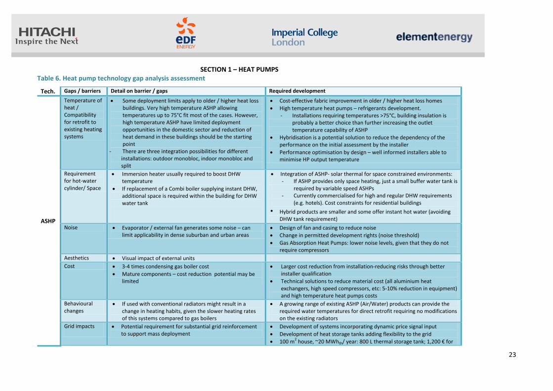
23
SECTION 1 – HEAT PUMPS Table 6. Heat pump technology gap analysis assessment
Tech. Gaps / barriers Detail on barrier / gaps Required development
ASHP
Temperature of heat / Compatibility for retrofit to existing heating systems
Some deployment limits apply to older / higher heat loss buildings. Very high temperature ASHP allowing temperatures up to 75°C fit most of the cases. However, high temperature ASHP have limited deployment opportunities in the domestic sector and reduction of heat demand in these buildings should be the starting point
- There are three integration possibilities for different installations: outdoor monobloc, indoor monobloc and split
Cost-effective fabric improvement in older / higher heat loss homes
High temperature heat pumps – refrigerants development. - Installations requiring temperatures >75°C, building insulation is
probably a better choice than further increasing the outlet temperature capability of ASHP
Hybridisation is a potential solution to reduce the dependency of the performance on the initial assessment by the installer
Performance optimisation by design – well informed installers able to minimise HP output temperature
Requirement for hot-water cylinder/ Space
Immersion heater usually required to boost DHW temperature
If replacement of a Combi boiler supplying instant DHW, additional space is required within the building for DHW water tank
Integration of ASHP- solar thermal for space constrained environments: - If ASHP provides only space heating, just a small buffer water tank is
required by variable speed ASHPs - Currently commercialised for high and regular DHW requirements
(e.g. hotels). Cost constraints for residential buildings
• Hybrid products are smaller and some offer instant hot water (avoiding DHW tank requirement)
Noise Evaporator / external fan generates some noise – can limit applicability in dense suburban and urban areas
Design of fan and casing to reduce noise
Change in permitted development rights (noise threshold)
Gas Absorption Heat Pumps: lower noise levels, given that they do not require compressors
Aesthetics Visual impact of external units
Cost 3-4 times condensing gas boiler cost
Mature components – cost reduction potential may be limited
Larger cost reduction from installation-reducing risks through better installer qualification
Technical solutions to reduce material cost (all aluminium heat exchangers, high speed compressors, etc: 5-10% reduction in equipment) and high temperature heat pumps costs
Behavioural changes
If used with conventional radiators might result in a change in heating habits, given the slower heating rates of this systems compared to gas boilers
A growing range of existing ASHP (Air/Water) products can provide the required water temperatures for direct retrofit requiring no modifications on the existing radiators
Grid impacts
Potential requirement for substantial grid reinforcement to support mass deployment
Development of systems incorporating dynamic price signal input
Development of heat storage tanks adding flexibility to the grid
100 m2 house, ~20 MWhth/ year: 800 L thermal storage tank; 1,200 € for

24
equipment + 800 € for installation- without tax)
Development of control solutions to use the thermal inertia of the building as heat storage to add flexibility to the grid
Lack of skilled and experienced installers
High dependency of the performance on the installer
The performance of the installation will depend on: - the initial assessment of the installer regarding the
ASHP requirements (heating capacity and temperature range)
- the quality of the installation, (may include work on the existing radiator loop to ensure suitable water flow distribution)
- the settings of the control parameters
Increase resourcing / capacity of Microgeneration Certification Scheme (or similar) to maintain quality of accreditation standards of installers (i.e. increase in the installation base is required while maintaining appropriate barriers to entry. There is a risk of installation companies that are not trained in heat pump installation moving into the market, driven by incentives).
Heat pump associations have played an important role in European heat pump markets. Associations have supported R&D, system testing and installer training. Heat pump associations have also provided dispute resolution services for underperforming heat pump installations.
GSHP
Requirement of hot-water cylinder/ Space
Internal space limitations:
Water tank is required External space:
Limited applicability due to space requirements for boreholes or ground loops
Space for ground exchangers. Integration issues: - compatibility with the heat pump capacity and
building needs - compatibility with the area available around the
building
Large ground exchanger fields can be used as seasonal heat storage
Cost Boreholes are a significant additional cost compared to ASHP
Vertical ground collectors are more expensive than horizontal ones (~3-4 times the cost of a condensing gas boiler)
Solar assisted GSHPs are cheaper than pure GSHPs
Technical solutions to reduce ground exchangers installation costs: smaller drilling rigs, standardised installation process.
Regionalised drilling industry. This reduces the transportation time for drilling rigs and also means that local contractors become expert in the particular ground conditions.
Solar assisted GSHP with unglazed solar collector has capital costs lower than pure GSHP
For solar assisted GSHP: solar collector integration
Compatibility with heat pump capacity and ground exchangers sizing
Compatibility with area available on the building roof
suitable brine flow rate in the ground exchangers and unglazed solar collectors
Development of installer base • Integration of all system elements (ground exchangers, unglazed
solar collectors, heat pump and control) has to be supported by a competent installer
Currently, solar assisted GSHPs are developed for office or big

25
Possibility to produce DHW with unglazed solar collectors during summer
residential buildings (500-7000 m2), not for single family houses.
Commercialisation in process
Hybrid ASHP (packaged-integrated, unpackaged-extended)
Cost 2-3 times condensing gas boiler costs
Overall cost reductions 10-20% by 2020
See ASHP
Integration ASHP - boiler
Integration will allow optimisation of the system (in terms of costs or CO2 emissions)
Optimisation of the integration of the hydraulic connection and controls between the boiler and ASHPs for Hybrid ASHP with Extended HP coverage system
Space See ASHP See ASHP
Noise See ASHP
See ASHP
Gas Absorption heat
pump
Space Suitable for large scale residential buildings (hotels, nursing homes…)
Cost / lifetime Technical solutions to reduce material cost (all aluminium heat exchangers, high speed compressors, etc)
Back-up system depending on ambient T
If the ambient temperature is lower than -5 deg. C a back-up boiler is required
Technical development
Efficiency improvement
Ammonia used typically as refrigerant. Hazardous, leads to high pressure
Development of thermodynamic solutions to increase G.U.E. (Gas
Utilisation Efficiency)
Refrigerant developments

26
SECTION 2 – mCHP Table 7. mCHP technology gap analysis assessment
Tech. Gaps / barriers Detail on barrier / gaps Required development
LT PEM
mCHP
Requirement for auxiliary boiler and HW tank & potentially larger thermal store to optimise operation/ Space
Volume of these systems ~ 2.5 bigger than conventional condensing boilers
Development of wall-hung systems might be necessary for customer uptake in the UK
Other mCHP technologies (e.g. SE mCHP) offer commercially available wall-hung units and are able to produce instantaneous water heating. However, this combi systems are not commercially available in UK (the Remeha eVITA combi SE mCHP is available in Germany and The Netherlands)
Low water output T – appropriate heat distribution retrofitting
Low water output temperatures (~60 deg. C) might require the retrofit of appropriate heat distribution systems such as low T radiators of under floor heating
HT PEM mCHP provide higher output temperatures that address this problem
Requirement for external reformer for fuel processing
LT PEM FCs have low tolerance to CO that implies the need of fuel processing
~80% of the BoP cost is due to the fuel processor
Improvement in fuel processor and system configuration
HT PEMFC have higher tolerance to CO and do not require an external reformer
Durability / on/off cycle life
Currently, lifetimes of ~40,000 h. Potential for improvement
LT PEM FC, however, offer the longest lifetimes along FCs (compared with SOFCs affected by durability and cycling issues and HT PEMFC affected by harsher temperature conditions. Lifetimes ~20,000 h)
R&D in this area
Integration with thermal storage
Significant if the fuel cell is electricity led to avoid heat rejection in times for high electricity-low heat demand profiles
Development of thermal storage (low TRL) and integration with LT PEMFC – companies are studying this at the moment with views to commercialisation
High costs Capital costs ~ five times higher than a conventional boiler
Ene-farm residential LT PEM (launched April 2013. Panasonic, 0.75 kW system, Japan): £18,700/kW (i.e. capex ~£14,000)

27
HT PEM
FC
Application development for the domestic market
• Small number of low nameplate capacity systems commercially available (e.g. Clear Edge offers systems from 5 kW) limits the application of this technology to systems with higher thermal demand (multifamily residential buildings)
Feasibility studies and prototype development for the domestic market
Supply chain development
Small supply chain opportunities for Membrane Electrode Assemblies (MEAs)
Increase competition in MEAs supply (e.g. at the moment, BASF main player)
Lifetime Membrane lifetime is seen by many researchers as the bigger barrier for commercialisation of HTPEMFC
Catalysts durability, especially in acid based systems
R&D in new materials
Space Volume occupied by a 5 kW HT PEM unit is 10 times bigger than a 60 kW condensing gas boiler
Volume occupied by a 5 kW HT PEM unit is 4 times higher than a 0.75 kW LT PEM
Weight 5 kW HT PEM vs 60 kW condensing gas boiler (kg): ~1,000 kg vs <100 kg
Simplification of the system
SOFC mCHP
Requirement for thermal storage to optimise operation
Thermal storage provides a solution to the adverse impact of on-off cycling on SOFCs due to thermal stress (but note that space constraints might apply)
Thermal storage development and integration with SOFCs
Other mCHP technologies (e.g. SE, ICE can ramp up and down rapidly)
Long start-up times
Due to the high operating temperature of this technology, start-up times are long.
The integration of SOFC and electricity storage could provide a solution to this constraint
- Could provide fast response to load following - Development of bespoke DC / DC converter between SOFC, battery and
load necessary - Projects undergoing for this integration
High costs Capital costs ~ 6-7 times higher than a conventional boiler (Enefarm Type S, 0.7 kW~£?27,000/kW. i.e. capex ~£?17,000)
Materials innovation - There has been a general trend to try to decrease operating temperatures
of SOFCs as high temperatures require expensive materials/construction (however, a shift below c.650C is required to benefit from standard steels and therefore cheaper materials/manufacture)
Size Space requirements to accommodate mCHP and associated thermal storage
SE mCHP
Efficiency improvement
Improve efficiency at low power

28
High costs 2 - 3 times the costs of a condensing gas boiler Reduction through economies of scale and technical innovations
Lack of customer awareness
Together with high capital cost, this might be another reason for its small uptake, given that it is commercially available. After ICE mCHP, the mCHP technology has been in the market for longest time
Supply chain development
Volume production: development of automated assembly of stacks
PM synchronous generator implies the use of Rare Earths, which could mean a resource constraint. Competition with wind turbines, batteries.

29
SECTION 3 – BIOMASS BOILER, HDTS and HYBRID SOLAR THERMAL Table 8. Biomass boiler, HDTS and hybrid solar thermal technology gap analysis assessment Tech. Gaps / barriers Detail on barrier / gaps Required development
Bio
mas
s b
oile
r
Local availability of stock and fuel supply; space for appropriate storage
Constraints in fuel supply
Biomass fuels require careful storage to avoid deterioration and air quality risk to operators
Supply chain development
Sensors to track key parameters such as humidity, water content and fungal growth (impacting on air quality in the store)
Hassle – fuelling, de-ashing, and maintenance
Alkaline nature of biomass implies fouling and corrosion, resulting in a high economiser failure rate
Higher maintenance requirements than biomass boilers (emptying ashbin, cleaning flue tubes)
Study of economiser failure in biomass boilers, development of predictive tools for slagging and deposition control in boilers
Air quality impacts
Air quality concerns (NOx and CO/CO2) of burning biomass in urban areas could restrict their application in these spaces . Importance of combustion control systems (problem more challenging than in gas boilers, as reaction temperatures are higher, and allow the reaction of atmospheric O2 and N2)
Filter cleaning technology and combustion control mechanisms under development to reduce particle emissions
Back up boiler and thermal storage integration
Domestic biomass boilers will usually provide the base load for the heating system, and a back-up boiler sized to meet the peak load will be needed in most cases
The technical characteristics of biomass boilers, that require them to operate continuously in order to achieve the higher efficiencies, make integration of biomass boilers with thermal storage systems important
Thermal storage development
Appropriate control systems
Space
Space requirements both internal (boiler) and external (fuel storage)
10-15 kW biomass boiler ~ 1.5-2 times the volume of a condensing gas boiler

30
Th
erm
al
sto
re /
HD
TS
De-stratification of thermal store
Affects heat source capacity control
Can be created due to incorrect BoP design (e.g. over-pumping by fixed speed pumps)
Appropriate design team and installer base
There are commercial solutions proposing “stratification by design” – integration of several modular salt hydrate PCMs storages (< 5 kWh) with different melting points into a PCM thermal store. Modules are separated, avoiding de-stratification by an incorrect BoP design (See appendix)
Low TRL Although HDTS will have a key role for the future of smart heat energy systems, it is still at an early stage of development
Development, demonstration and commercialisation of heat-source tailored applications
Further research/development/demonstration of metal hydrides as thermal storage for the domestic sector
Further research/development/demonstration of PCM salt hydrates for storage for the domestic sector (avoid paraffin’s safety issues)
Technical barriers Several barriers associated with different types of PCMs (e.g. although salt hydrates present the advantage of being not flammable, as is the case for paraffin-based PCMs, and of having twice the energy density of the latter, they present issues associated with corrosion)
Further development and demonstration of HDTS e.g. for PCM integrated in HW tank storage, there is scope for development of the design parameters for optimal performance:
1. PCM shape (e.g. PCM tanks with inner core, with inner balls, or with inner tubes) 2. Operating temperature
Costs The Technology Innovation Needs Assessment published in 2012 reported capital costs for daily PCM heat storage for small scale systems (i.e. suitable for homes) of £530/kW
Supply chain and economies of scale development
Hyb
rid
so
lar
the
rmal
an
d g
as
bo
ile
rs
Space Storage tank essential for solar water heating Integration of PCMs in HW tanks Due to high PCMs costs, this solution might just be appropriate in systems with space constraints, in the short term
Lack of customer confidence in / awareness of technology
Awareness of solar thermal technology is reasonably good, although some negative perception due to issues with installations of earlier generations of the technology.
Scepticism about the effectiveness of solar thermal in UK.
Increase customer confidence in the technology - Remove information barriers for the potential consumer to easily find
an installer
Customer training about the optimal use of the technology - Adopters may not know how best to use solar heated water to
minimise back-up fossil fuel consumption
Integration issues Solar thermal technology could provide ~60% of household’s hot water in a cost-effective manner (EST, 2011)
Optimisation of system integration

31
4.2.1 Cross-cutting issues and enablers
The technology gap analysis has identified a number of cross-cutting issues that are common to
several of the technologies. These common issues are summarised in Table 9.
It is clear that high density thermal storage and smart control systems have a role to play in a
range of technology packages. When integrated with primary heating appliances, these
technology packages (or systems) facilitate demand reduction, more cost-effective operation
and enable smart control strategies, such as demand side response, which can be beneficial to
the operation and management of the electricity supply system. These key enabling
technologies are discussed in more detail in Appendix C – Key enabling technologies.
In the Appendix, an analysis of Heat Pump and Fuel Cell mCHP integration issues is presented,
and a description of energy storage at the building and Host Space Environment level is
provided. Regarding the control strategy, options for control strategy and their associated
barriers are also presented as well as the main barriers at the building (costs, lack of incentives
for homeowners, land of standard protocols) and Host Space Environment levels, in the form of
Demand Side Response coupled with heat pumps or mCHP (consumer acceptance, lack of
incentives to homeowners to participate in DSR schemes, costs, lack of standardisation of
protocols within the homes and between home and Demand Response application).
4.3 Host Space Environment level assessment
The preceding sections assessed the barriers and gaps associated with integration of low carbon
heating systems within buildings. In this section, we consider the impact of high levels of
deployment of low carbon heating options within local areas, using the HSEs as the framework
for the assessment. The technology deployment scenarios used for this analysis were
introduced in Section 4.1 and are taken from the DECC 2050 Pathways analysis.
When considering technology deployment at the area-level, it is necessary to consider network
technologies that are deployed outside the confines of individual buildings. Under low
electrification scenarios, the DECC 2050 Pathways consider the potential for high levels of
penetration of district heating, served by combined heat and power (CHP) technologies and
alternative sources, such as waste heat. Under high electrification scenarios, the DECC Pathways
envisage a large proportion of heat demand being met by air and ground source heat pumps.
The impact of high levels of electrification of heat on local electricity distribution networks is a
widely recognised challenge and significant resources are being employed to develop solutions,
technical and commercial, to mitigate these impacts and reduce network investment costs. In
this section we assess the impact of deployment of district heating and smart network
technologies. Further discussion of the technologies and their development issues is given in
Appendix D – Network Solutions.
In the following section, the selected technology deployment scenarios are assessed at the HSE-
level in terms of their cost implications and carbon reduction impact.

32
4.3.1 Cost analysis
The scale of required investment will be an important factor in assessing the technology and
systems options for future low carbon heating infrastructure. Government will seek to identify
pathways to decarbonisation of the economy that incur least resource cost to the UK.
Consumers and businesses will not be persuaded to invest in low carbon heating technologies
that are not cost-competitive with incumbent systems, at least not without generous subsidies
or stringent regulations.
A high-level analysis of the capital cost implications of the technology deployment scenarios
introduced in Section 4.1 has been undertaken for each of the relevant HSEs. Given the time
horizons for large-scale deployment of low carbon heating technologies, the cost analysis has
been performed on today’s costs and on the basis of forecast costs for 2030. The capital cost
implications, presented as £/dwelling, are shown in 34 (the capital cost assumptions for each of
the technologies are given in the appendices).
In the rural HSEs, the High HP (no DH) scenario is least cost under today’s cost assumptions.
Note that this is partly due to the assumption that the majority of the mCHP systems installed in
the High mCHP scenario are fuel cell based and the high current costs of fuel cell mCHP products
($20,000/kW). In the suburban and urban HSEs the least cost scenarios are those that include a
significant penetration of district heating networks. The Low Elec. scenario in particular, which
involves high district heating penetration and Stirling engine mCHP in those dwellings not
connected to a heat network, compares favourably against other scenarios that involve higher
penetration of heat pumps and fuel cell mCHP.
Under 2030 cost assumptions in the suburban and urban HSEs the capital costs related to the
High HP and Mixed scenarios have dropped considerably relative to those of the more district
heating based scenarios. The assumption here is that while some cost reduction may be
achieved in centralised thermal plant, such as biomass CHP, there is limited scope for cost
reduction in the district heating infrastructure. Despite the assumption of limited cost reduction
for DH, the Low Elec. scenario remains the least cost scenario under 2030 assumptions. This is in
part due to a relatively conservative assumption on the scope for cost reduction of heat pumps.
While the market for heat pumps in the UK is currently limited, the major components in heat
pumps (such as the compressors) are very mature in other markets and manufactured in large
volumes (for example the commercial HVAC market). The development of the UK heat pump
market is unlikely to drive significant cost reduction in these components. The installation cost
of a heat pump system in the UK is estimated to be 35 – 50% of the total installed cost in the
current market. Some cost reduction in this element of the total cost is expected as the market
grows and the supply chain becomes more developed. The largest cost reduction has been
attributed to fuel cell mCHP systems. This technology is currently pre-commercial in the UK,
with only a handful of installations to-date (total experience across Europe is around 1,000 units;
the largest market is Japan, where a few tens of thousands of units have been installed to-date).
Significant cost reductions are expected to be achieved for fuel cell mCHP as the manufacturing
4 The capital costs analysis does not account for the time to turn-over the heating system stock or any
replacement costs (all costs are undiscounted).

33
capacity of fuel cell stacks increases. This could be partly driven by other markets, such as
automotive. It has been assumed that fuel cell mCHP systems achieve costs of $3,500 -
$5,000/kW by 2030 (Staffel and Green, 20125).
The impact of the more aggressive assumption for cost reductions in mCHP can be seen clearly in
eth 2030 cost assessment for the rural HSEs. In this case the High mCHP option is significantly
the least cost solution.
5 Staffel I., Green R., The cost of domestic fuel cell micro-CHP systems, 2012

34
Table 9. Common cross-cutting issues across technologies
GENERAL
HPs mCHP Biomass boiler
ASHPs GSHPs Hybrid ASHP FC mCHP SE mCHP
SPA
CE
• Combi boilers (75% of new installed boilers 2011). High penetration driven by space constraints for DHW/thermal storage in many newer homes
Require DHW tank
Not suitable for flats
-Smaller than ASHP -Some offer instant HW
Back up boiler, DHW tank and thermal storage for flexibility of system (wall hung units seem necessary for UK uptake)
Back up boiler can be integrated in SE mCHP
Not suitable for flats Back-up boiler required
DES
IGN
• Match capacity of heat system with demand
• Technical improvement by design: e.g. stratification by design in PCMs systems -under development
Mismatching of HP capacity and heat demand addressed as an important failure Hybrid ASHP Sizing an hybrid heat pump for a given installation is often less critical than for pure ASHP or GSHP
Minimise system components (e.g. Balance of plant with high failure rates)
In systems not correctly designed, the fossil fuel boiler will take over the load intended to be supplied from biomass, with the subsequent carbon savings reduction that this implies
INST
ALL
• Lack of skilled and experienced installers for tailored system design. Performance is determined by: a) Initial installer assessment b) installation quality c) controls parameters set by installer
• Technical solutions could reduce installation costs (standardisation) • ASHP: EST trials revealed critical importance of installation in ASHPs (e.g. Tuning of control parameters, such as the “heat curve” (water temperature) has a high influence
on system performance. Work on the radiator loop sometimes necessary to improve flow distribution)
INTE
GR
ATI
ON
WIT
H
THER
MA
L ST
OR
AG
E
Enables selling demand side response services and arbitrage opportunities
Thermal storage enabling flexibility of grid (peak shaving, decentralised generation) Thermal storage is less cost effective with Hybrid ASHP as bi-energy already offers greater flexibility
PEMFC: Thermal storage integration with electricity led PEMFC to avoid heat rejection in times of high electricity-low heat demand profiles SOFC: When integrated with thermal store can be run throughout extended periods of time avoiding on-off cycling that causes thermal stress SE mCHP: high thermal SE output requires the storage (with ability to decouple heat production from demand) to be big enough to enable running for long hours (or high thermal demand) before significant electrical generation occurs
The technical characteristics of biomass boilers, that require them to operate continuously in order to achieve the higher efficiencies, make important the integration of biomass boilers with thermal storage. Efficiency highly affected by cycling
CO
NTR
OLS
Enables selling demand side response services and arbitrage opportunities
• HPs equipped with control system based on air T measurement at least and internal thermostat
• Ideally Communication between HP and grid – Design of systems incorporating dynamic price signal input (particularly interesting for Hybrid ASHP)
Optimised mCHP controls to minimise operating costs and maximise CO2 savings – Different control strategies (i.e. heat/electricity/least cost led), have different implications for each FC mCHP technology

35
Figure 3. Capital cost implications of technology deployment scenarios
CU
RR
ENT
CO
STS
20
30
CO
ST P
RO
JEC
TIO
NS
£0
£5,000
£10,000
£15,000
£20,000
£25,000
£30,000
Rural village Market Town
Ave
rage
cap
ital
co
st p
er
dw
elli
ng
(£)
Capital cost of technology deployment scenario - Rural
HSEs
Mixed
High HP (No DH)
High mCHP (No DH)
£0
£2,000
£4,000
£6,000
£8,000
£10,000
£12,000
£14,000
£16,000
£18,000
£20,000
Suburbanresi
Suburbancentre
Urban resi Urban centre
Ave
rage
cap
ital
co
st p
er
dw
elli
ng
(£)
Capital cost of technology deployment scenarios - Urban
and Suburban HSEs
Low elec
Mixed
High HP
High DH
£0
£2,000
£4,000
£6,000
£8,000
£10,000
£12,000
Rural village Market Town
Ave
rage
cap
ital
co
st p
er
dw
elli
ng
(£)
Capital cost of technology deployment scenario - Rural
HSEs
Mixed
High HP (No DH)
High mCHP (No DH)
£0
£2,000
£4,000
£6,000
£8,000
£10,000
£12,000
£14,000
Suburbanresi
Suburbancentre
Urban resi Urban centre
Ave
rage
cap
ital
co
st p
er
dw
elli
ng
(£)
Capital cost of technology deployment scenarios - Urban
and Suburban HSEs
Low elec
Mixed
High HP
High DH

36
4.3.2 Grid reinforcement costs
The costs presented in the preceding section are those related to the installation of technologies
within the dwellings. Deployment of certain technologies will result in costs being incurred to
reinforce the electricity distribution network, particularly in the case of those technologies that
involve electrification of thermal demand and those technologies that have potential to feed
electricity back to the network. There are a range of technologies and strategies that can be
deployed to mitigate these costs, as described in Appendix D – Network Solutions.
In this section we present an analysis of the costs related to the impact of heating technologies on
the electricity distribution network, under a range of control strategies.
Firstly, the network reinforcement costs related to an uncontrolled strategy (i.e. business-as-usual
reinforcement) is tabulated below for each of the HSEs and each of the relevant technology
deployment scenarios.
Table 10. Reinforcement costs across HSEs related to business-as-usual reinforcement
HSE \ Scenario Reinforcement cost (£/connection)
Low
electric
Mixed High HP High DH High HP (No
DH)
High
mCHP
(No DH)
Village 6 – 7 850 – 970 0
Market town 100 – 140 2,000 – 2,500 0
Suburban residential 0 110 – 140 770 – 930 150 – 190
Suburban with local
centre
0 120 – 160 790 – 960 150 – 200
Urban (residential) 0 0 300 – 340 0
Urban centre 0 0 140 – 160 0
No significant network reinforcement costs are incurred in the low electrification scenario or in the
High mCHP case. The scenarios that have an impact on the electricity distribution network that
requires reinforcement are those that include an element of electrification of heat load. The
reinforcement costs for these four scenarios are shown in the chart below for each of the relevant
HSEs. The reinforcement cost is disaggregated between the voltage levels.

37
Figure 4. Reinforcement costs across scenarios and HSEs (LV + DT = Low voltage network and distribution transformers; HV = High Voltage network; PS = Primary Substations and EHV = Extra high voltage network)
There is a large variability between the cost impacts of high heat pump penetration between the six
HSEs. Generally, the cost implications tend to be greater in the more rural HSEs, particularly the
Market Town HSE, in which a network reinforcement cost of nearly £2,500 per connection is
triggered by the High HP scenario (80% penetration of heat pumps). It is also clear that the low
voltage network and distribution transformers are the most significant component of the
reinforcement cost.
We focus on the High HP scenarios for the following analysis of the impact of mitigation measures,
as these are clearly the scenarios with greatest implications for the networks. A full set of results for
each scenario, HSE and control strategy is provided in the appendices (See Appendix D – Network
Solutions).
Given the high concentration of reinforcement costs in the LV network, it is expected LV voltage
control will provide significant benefits. A comparison of reinforcement costs across the HSEs
between the uncontrolled case and case with LV voltage control is provided in the figure below (all
cost ranges relate to the High HP deployment scenarios).
0
500
1,000
1,500
2,000
2,500
Vill
age
Mar
ket
tow
n
Sub
urb
an r
esid
enti
al
Sub
urb
an w
ith
loca
l cen
tre
Sub
urb
an r
esid
enti
al
Sub
urb
an w
ith
loca
l cen
tre
Urb
an (
resi
den
tial
)
Urb
an c
entr
e
Sub
urb
an r
esid
enti
al
Sub
urb
an w
ith
loca
l cen
tre
Vill
age
Mar
ket
tow
n
Mixed High HP High DH High HP (NoDH)
Rei
nfo
rce
men
t co
st (
£/c
on
nec
tio
n)
From bottom: Scenario, HSE
Reinforcement cost: Uncontrolled (Max)
EHV+
PS
HV
LV+DT

38
Figure 5. Reinforcement costs across HSEs between uncontrolled case and with LV voltage control
Reductions in the reinforcement cost in the LV voltage control case are seen across the HSEs. The
impact is most significant in the Market Town and two suburban HSEs.
The further reinforcement cost reductions that can be achieved under other control strategies are shown in the figures below for a selection of HSEs. The control strategies that have been assessed are: • Grid storage • Demand Side Response (DSR) • Energy efficiency (10% load reduction) • D-FACTS (Distributed Flexible Alternative Current Transmission Systems).
The impact of these measures has been assessed when combined with LV (low voltage) control and
without.
Demand Side response is the control strategy that achieves the greatest further reduction in
reinforcement costs. This is consistently the case across the HSEs (although the range of potential
costs under the DSR case is large).
D-FACTS and energy efficiency also provide benefit and are fairly comparable to each other in terms
of the impact (although the cost of fabric efficiency measures is not factored into this analysis). The
benefit achieved by the introduction of grid storage is expected to be marginal on the basis of this
analysis.
0 500 1000 1500 2000 2500 3000
Village
Market town
Suburban residential
Suburban with local centre
Urban (residential)
Urban centre
Village
Market town
Suburban residential
Suburban with local centre
Urban (residential)
Urban centre
No
LV
vo
lta
ge c
on
tro
lLV
vo
ltag
e c
on
tro
l
Reinforcement cost (£/connection)

39
Figure 6. Distribution network impacts in Market Town
Figure 7. Distribution network impacts in Urban residential
0 500 1000 1500 2000 2500 3000
Uncontrolled
Grid storage 10%
DSR 50%
Efficiency 10%
D-Fact
Uncontrolled
Grid storage 10%
DSR 50%
Efficiency 10%
D-Fact
No
LV
vo
lta
ge c
on
tro
lLV
vo
ltag
e c
on
tro
l
Reinforcement cost (£/connection)
Distribution network impacts: Market Town
0 50 100 150 200 250 300 350 400
Uncontrolled
Grid storage 10%
DSR 50%
Efficiency 10%
D-Fact
Uncontrolled
Grid storage 10%
DSR 50%
Efficiency 10%
D-Fact
No
LV
vo
lta
ge c
on
tro
lLV
vo
ltag
e c
on
tro
l
Reinforcement cost (£/connection)
Distribution network impacts: Urban resi

40
4.4 Carbon emissions impact
The extent of the CO2 emissions reduction that technologies can achieve is a key criterion in the
selection of heating technologies and systems that will be applicable in the 2030 and 2050 time
horizons. In this section we present a high-level analysis of the potential scale of CO2 reduction
delivered by the various technology deployment scenarios.
The basis of this analysis is an assessment of the CO2 reduction at the dwelling level. The Element
Energy Housing Energy Model (HEM) has been used to assess the CO2 reduction delivered by each
technology in each of the twelve standard house types. In combination with the primary heating
technology, it is assumed that a package of energy efficiency measures is also applied to each house
type (the efficiency measures included in the package are detailed in the appendices: Appendix F –
Cost and Carbon emissions assessment).
The results of this assessment, in terms of carbon reduction compared to the baseline house types
for each technology package, are provided in the appendices (Appendix F – Cost and Carbon
emissions assessment). The key findings are as follows:
• The largest CO2 reductions are achieved by the biomass boiler, due to the very high fraction of
renewable heating achieved in this case – assuming that the biofuel is accredited to come from
sustainable sources.
• ASHP deliver a marginal improvement in gas heated homes (based on an ASHP Seasonal
Performance Factor, SPF, of 2.5). GSHPs provide a slightly greater improvement due to their
higher SPF (3.1).
• Generally, larger CO2 reductions are delivered by all technologies in the electrically heated
homes.
Based on the CO2 reduction assessment at the house type level, an analysis of the CO2 impact of the
technology deployment scenarios across the HSEs was undertaken.
The CO2 reductions delivered by each of the technology deployment scenarios in the HSEs is shown
in Figure 8 as a percentage reduction on the baseline emissions.
Given that, through this process, we are seeking to identify high priority technologies that could play
a significant role in low carbon heating systems on timescales up to around the 2030s, we are
interested not only in the levels of CO2 reduction that could be delivered under today’s energy mix
assumptions (compared with current levels attributed to residential heating provision), but also in
the CO2 emissions performance under a future set of assumptions. Potentially the most significant
change anticipated to occur over the period to 2030 is a significant drop in the carbon intensity of
the grid electricity mix, primarily due to the expected large-scale deployment of off-shore wind
turbines. To assess the impact of a reduction in grid CO2 emissions intensity, we have analysed the
CO2 emissions associated with each of the technology deployment scenarios under an assumed grid
CO2 intensity of 0.2 kgCO2/kWh. These results are also presented in Figure 8.

41
• Under current assumptions the greatest CO2 reduction is delivered by those scenarios that
involve large-scale penetration of district heating. High heat pump scenarios achieve the lowest
CO2 reduction across all scenarios.
• The strong CO2 benefit delivered by the district heating scenarios is sensitive to the assumed
penetration of renewable fuel. However, even under an assumption of 100% of district heating
load is served by gas CHP, the CO2 emissions performance is better than heat pump performance
under current grid CO2 intensity assumptions.
• Under the assumption of a grid CO2 intensity of 0.2 kgCO2/kWh, the High HP scenarios provide
the greatest CO2 reduction across all HSEs. Note that the comparison between high heat pump
scenarios and high DH is relatively close at this grid CO2 intensity (assuming a high renewable
fuel source penetration in the DH scenarios).
• It is interesting to note that the CO2 emissions performance of mCHP deteriorates very
significantly as the grid CO2 intensity falls. This is most clearly seen by comparison of the High
mCHP scenario between 2013 and 2030 assumptions. The implication of this is that the window
of opportunity for mCHP is short, if decarbonisation of the electricity sector proceeds as
planned. This has knock on implications so far as identifying technology gaps and development
opportunities for the ETI’s consideration – ie, only if cost reduction can be fast-tracked via ETI
involvement would such involvement be commercially worthwhile
• No change in the CO2 intensity of net-bound gas supply is assumed in this analysis. A reduction
in the gas CO2 intensity could extend the opportunity for mCHP to deliver material CO2
reduction. This could be achieved by introduction of biomethane into the gas grid (supply issues
and potential to complicate the fuel processing equipment required by fuel cells) or renewably
generated hydrogen.

42
CU
RR
ENT
GR
ID C
O2
INTE
NSI
TY
203
0 P
RO
JEC
TED
GR
ID C
O2
INTE
NSI
TY
Figure 8. CO2 reductions by each of technology deployment scenarios in the HSEs as a percentage reduction on the baseline emissions
0%
5%
10%
15%
20%
25%
30%
35%
40%
Rural village Market Town
% C
O2
re
du
ctio
n c
om
par
ed
to
bas
line
CO2 reduction compared to baseline
Mixed
High HP (No DH)
High mCHP (No DH)
0%
5%
10%
15%
20%
25%
30%
35%
40%
45%
50%
Suburban resi Suburbancentre
Urban resi Urban centre
% C
O2
re
du
ctio
n c
om
par
ed
to
bas
line
CO2 reduction compared to baseline
Low elec
Mixed
High HP
High DH
0%
10%
20%
30%
40%
50%
60%
Rural village Market Town
% C
O2
re
du
ctio
n c
om
par
ed
to
bas
line
CO2 reduction compared to baseline
Mixed
High HP (No DH)
High mCHP (No DH)
0%
10%
20%
30%
40%
50%
60%
Suburban resi Suburbancentre
Urban resi Urban centre%
CO
2 r
ed
uct
ion
co
mp
are
d t
o b
aslin
e
CO2 reduction compared to baseline
Low elec
Mixed
High HP
High DH

43
4.5 Packages of solutions
Assuming that technology packages will include appropriate and feasible levels of fabric insulation upgrade, the following table presents examples of the
allocation of suitable packages of technologies to the different HSEs. A collection of packages with potential for decarbonisation of the domestic heating
market up to the medium term at the building and community level are presented, although the list does not intend to be comprehensive nor to prioritise
certain specific packages for each HSE.
HSE Heat
distribution
Heat
source
(building
level)
Storage Manage,
monitoring
& control
Heat
network
Electricity
distribution
Distributed
generation
Manag.
Services
Comments
Village Conventional
radiators
Biomass
boiler
HDTS HEMS/HAN LV control/
DSR
EMS
Conventional
radiators
SE mCHP HDTS HEMS/HAN DSR EMS SE mCHP systems, given their high heat to
power ratios and high capacity of currently
available systems, are better suited to
dwellings with high thermal demand (e.g.
larger, older dwellings)
Market
town
Conventional
radiators
Biomass
boiler
HDTS HEMS/HAN LV control/
DSR
EMS
Conventional
radiators
SE mCHP HDTS HEMS/HAN DSR EMS SE mCHP systems, given their high heat to
power ratios and their power capacities
currently available, could better suit systems
in which a high thermal demand is necessary,
as bigger dwellings

44
Suburban
residential
Fan-assisted
radiators
ASHP HDTS HEMS/HAN LV Voltage
control / DSR
EMS Noise constraints in densely constructed areas
SE mCHP HDTS HEMS / HAN DSR EMS
Fan-assisted
radiators
Communi
ty-scale
TES
HEMS/HAN Low T Heat
network
Large HP EMS Low T heat network can benefit areas with lower
densities
Suburban
with local
centre
Fan-assisted
radiators
ASHP HDTS HEMS/HAN LV Voltage
control / DSR
EMS
SE mCHP HDTS HEMS/ HAN LV Voltage
control/ DSR
EMS
Fan-assisted
radiators
Communi
ty-scale
TES
HEMS/HAN Low T Heat
network
Large HP EMS Low T heat network can benefit areas with lower
densities
Urban
(residential)
Fan-assisted
radiators
ASHP/ H-
ASHPs
HDTS HEMS/HAN LV Voltage
control / DSR
EMS Noise constraints in densely constructed areas.
Predominance of terraces makes space constraints
a smaller issue than in urban centre
FC mCHP HDTS HEMS / HAN DSR EMS
Fan-assisted
radiators
Communi
ty-scale
TES
HEMS/HAN Low T Heat
network
Large HP EMS
Communi
ty-scale
TES
HEMS / HAN DH
network
Community-
scale biomass
CHP
EMS
Urban
centre
Fan-assisted
radiators
ASHP/ H-
ASHPs
HDTS HEMS/HAN LV Voltage
control / DSR
EMS Space constraints, given predominance of flats

45
FC mCHP HDTS HEMS / HAN DSR EMS
Fan-assisted
radiators
Communi
ty-scale
TES
HEMS/HAN Low T Heat
network
Large HP EMS
Communi
ty-scale
TES
HEMS / HAN DH
network
Community-
scale biomass
CHP
EMS

46
5 Short-list of technologies / systems and rationale
The following technology short-list has been identified as the most promising technologies of those assessed in this work. These are technologies that have potential to be deployed at scale and deliver significant carbon reduction or to be key enablers of significant carbon reduction as part of integrated systems. For each technology, a brief summary of the rationale for selection is provided.
Table 11. Short-list of technologies
Cluster Category Technology Rationale for interest
Building-
level
Heat
distribution
Fan-assisted
radiators
• High potential applicability in low temperature
distribution heating systems
• Less disruptive and lower cost for retrofit than underfloor
heating
• Fan-assist provides more rapid heat-up characteristics and
even temperature distribution within the space
Heat source
ASHP
• Anticipated to be a key technology in the electrification of
heat
• More widespread and lower installed cost than ground
source systems
• Promise of very low carbon heat as grid decarbonises
Hybrid ASHP
• Potential to mitigate some barriers to ASHP deployment, such as compatibility with existing heating systems and reliance on immersion heater to provide DHW
• High potential for standardisation • For retrofits, can be an integrated solution or as an
extension to the existing gas boiler
Fuel cell mCHP
• Highly efficient form of localised energy generation
• Potential to provide balancing services / reserve and peak-
shaving services to utilities
• Opportunity for arbitrage based on the spark spread
Storage HDTS / PCM
• Potential to be a key enabler within smart heat systems,
e.g. to enable demand response using heat pumps or FC
mCHP
• Enable householders to utilise off-peak electricity for
heating
• Significantly reduced volume compared to traditional
storage mediums for an equivalent energy capacity
• Potential for a variety of form factors enabling storage to be better integrated into constrained spaces
• Potential to be used as a high thermal mass fabric component
Management,
monitoring &
control
Sensors /
actuators
• Enable energy demand reduction through more
sophisticated control strategies and software
development
• Enable DSR and increased home automation via communication with a HEMS gateway device

47
• Potential for development to control microgeneration and smart appliances
• Algorithm and software development
HEMS gateway /
HAN
• Potentially a key component in the smart home system.
• Enabler of better electricity system utilisation and system
balancing via demand-side response
• Could also enable control of microgeneration and smart
loads, such as EV charging and refrigeration
Heat network Low T district
heating network
• Well-suited to new build, energy efficient buildings
• Lower losses than from higher temperature distribution
systems
• Increased potential to utilise waste heat
• Increased potential to utilise renewable energy sources, including large-scale heat pumps.
Network-
level
Electricity
distribution
Voltage control
• LV voltage regulation techniques include a range of
technologies, such as:
• Solid state transformer
• In-line voltage regulator
• Conservation voltage reduction
• Voltage reduction based frequency control
• These LV voltage control technologies have potential to
increase the capacity of distributed generation, heat
pumps of EVs that can be connected by mitigating voltage
problems
D-FACTS • Soft Normally Open Points
• Static Synchronous Compensator (STATCOM)
• Unified Power Flow Controllers
DSR / thermal
storage
• Demand response technologies manage electricity
demand in response to supply conditions.
• DSR is an umbrella term relating to a number of
technologies that facilitate demand response, e.g.
HEMS/HAN, smart thermostat, auxiliary switches etc.
• Optimisation of DSR potential also requires advanced control systems at the network level
Distributed
generation
Community-
scale CHP
(biomass /
biogas)
• Potential to deliver very low carbon heat at community-
scale via district heating systems
• Cost competitive with microgeneration technologies in
areas of suitable heat density
• Facilitates better emissions control than smaller-scale distributed biomass plant (solid biomass fuel)
Community-
scale energy
from waste
• Potential to deliver low carbon heat at community-scale
via district heating schemes
• Integration of waste management with energy provision
has synergistic benefits for communities (e.g. landfill

48
reduction)
Service-
level
Cloud
management
service
• Cloud computing promises a lower cost means of
implementing smart homes systems
• Cloud based server enables reduced distributed computing and data storage resource, with no loss of quality of service
Energy
Management
Service
• The EMS functionality is key to providing an attractive
consumer offer to stimulate uptake of HEMS
• A common functional specification and interoperability
standards will facilitate widespread roll-out
EMS functionality can be developed to enable real time
control of consumer loads:
• Enables maximisation of the contribution of DG and DR to network balancing
• Reduces the constraints on increased penetration of low carbon technology
Reduced losses and improved security of supply

49
6 Criteria and proposed priority technologies / systems
In this section we propose, as requested by the ETI, a set of criteria that could be applied as the basis
for down-selecting from the longer-list of technologies provided in the preceding section to a short-
list for more detailed assessment. The proposed technologies are shown in Figure 9.
The ETI has asked the Consortium to propose a set of criteria to use to select up to four technology
development opportunities. We have based our proposed criteria on what we understand the ETI’s
objectives to be – i.e.:
To engage in technology development in some capacity so as to accelerate deployment in
the market
where an ETI financial investment is contemplated, the scale per investment is low millions
of pounds
To identify technologies that, when deployed at scale, can deliver a significant CO2 saving for
the UK
Identify technologies that can be demonstrated in field trials in three to four years.
There are certain tensions between these objectives. For example, the technologies that provide
the greatest opportunities for the ETI to engage are likely to be at lower TRL, with significant gaps to
overcome. Engagement in these technologies is unlikely to deliver near term financial returns.
There are several technologies that have the potential to deliver large CO2 reduction and that could
be demonstrated in the near term, but the opportunities for the ETI to engage are limited as the
technologies are at advanced stages of maturity.
The ETI will have a much clearer understanding of the relative priority of these objectives and, as a
result, may assess technologies differently against certain criteria or apply a different weighting to
the criteria when making the down-selection. We have assumed that, within the low carbon
technology space, priority should be given to those technologies that can make a significant
contribution to CO2 emissions reduction and provide an opportunity for the ETI to engage (e.g.
potential to offer commercial benefits, be demonstrated on a timescale consistent with SSHP Phase
2 demonstrations).
Figure 9. Mapping of highest priority technologies
CO2 reduction
potential
Opportunity for
the ETI to engage
Highest
priority
technologies
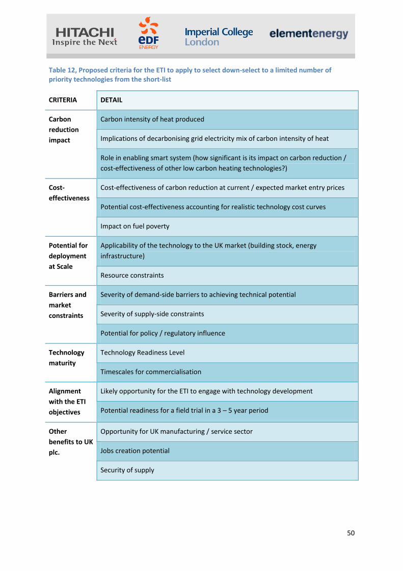
50
Table 12, Proposed criteria for the ETI to apply to select down-select to a limited number of priority technologies from the short-list
CRITERIA DETAIL
Carbon
reduction
impact
Carbon intensity of heat produced
Implications of decarbonising grid electricity mix of carbon intensity of heat
Role in enabling smart system (how significant is its impact on carbon reduction /
cost-effectiveness of other low carbon heating technologies?)
Cost-
effectiveness
Cost-effectiveness of carbon reduction at current / expected market entry prices
Potential cost-effectiveness accounting for realistic technology cost curves
Impact on fuel poverty
Potential for
deployment
at Scale
Applicability of the technology to the UK market (building stock, energy
infrastructure)
Resource constraints
Barriers and
market
constraints
Severity of demand-side barriers to achieving technical potential
Severity of supply-side constraints
Potential for policy / regulatory influence
Technology
maturity
Technology Readiness Level
Timescales for commercialisation
Alignment
with the ETI
objectives
Likely opportunity for the ETI to engage with technology development
Potential readiness for a field trial in a 3 – 5 year period
Other
benefits to UK
plc.
Opportunity for UK manufacturing / service sector
Jobs creation potential
Security of supply

51
On the basis of the technology short-list, these criteria and the supporting evidence presented in this
report, the following technologies are recommended to the ETI for further investigation. This short-
list has been identified following a scoring of the short-listed technologies against the proposed
selection criteria (see Appendix G). As noted above, the ETI may attach different levels of priority to
the various criteria, resulting in a different scoring and different technology selection.
• Community scale biomass / biogas CHP
• LV Voltage control technologies
• Energy Management Services and advanced network controls systems.
Technical considerations would need to include, in addition to technology specific factors, systems
design (where “system” includes building fabric, controls, management, storage, heat generator,
heat emitters, etc), optimisation and packaging. Non-technical factors would also need to be
considered including: supply chain coordination, installer competency, sale / lease and energy
services models, finance packages and system (as oppose to product) efficacy guarantees, etc. For
the community scale biomass/biogas CHP, the fuel supply chain and accreditation of fuel to be from
sustainable sources are additional factors which would need to be investigated.
In addition to the technologies identified above, assessment of the short-listed technologies on the
basis of the proposed criteria also highlights hybrid ASHP, High Density Thermal Storage (HDTS) and
HEMS / HAN as high priority technologies. These technologies were pre-selected by the ETI for
assessment in Task 5a. The analysis undertaken has validated the pre-selection of these
technologies, which in the Consortium’s view merit further consideration (beyond the scope of the
Task 5a assessment).

52
7 Next steps
In response to the ETI’s request, the Consortium has considered what further work could usefully be
carried out as a follow-on from this Task. As part of the further work to address the priority
technology gaps, the Consortium recommends the following work:
(i) a more detailed carbon performance analysis to compare the residential stock heating
carbon footprint with where that footprint needs to be in order to be consistent with a given carbon
emissions reduction trajectory – i.e. would the priority technologies, developed and deployed at
scale make such a contribution to the decarbonisation of residential heating as to be consistent with
the 2050 carbon emissions reduction target and decarbonisation trajectories;
(ii) re-scope Task 5b, incorporating learning from Task 5a and the ETI’s comments; identify
technology development priorities, e.g. costs to consumer (dependent on business model),
performance enhancement, functionality preferences, supply chain factors; identify potential
development partners / suppliers; propose options for the ETI to become involved to accelerate
deployment; assess technology/system maturity, the scale of development costs and likely
timeframe for development and deployment; likely benefits to the ETI; and
(iii) with the ETI and potential partners, create project development briefs (ie Systems Road
Maps and Technology Road Maps).

53
8 Appendices
Appendix A – Host Space Environments
A.1 House types
The six HSEs have been constructed from general principles and publicly available data to be
representative of over 75% of the national housing stock. The house types in each HSE are also
representative of the stock which we would expect to find in specific locations. Thus, for example,
the urban HSEs would contain more flats and terraced dwellings than the rural HSEs where there are
more detached houses. Using the standard source literature (e.g. national housing statistics, the
English House Condition Survey, etc), the actual dwelling types and their respective proportions,
conditions and densities in each of the six HSEs can be reliably established. The housing stock has
been classified into 12 house types, each of which is described by the following characteristics:
• main heating fuel (gas, electricity)
• dwelling type (detached, semi-detached, terraced, flats)
• standard of energy efficiency (good, poor)
• wall construction type (cavity wall insulation, unfilled cavities and solid wall).
Depending on the range of parameters, HSEs can be made as coarse grain/simple or as fine grain/
sophisticated as is required or can be accommodated within given time and budget envelopes for
investigation. The granularity can range from a grouping of house types according to certain
parameters (built form, location, etc.) to GIS mapping / postcode representation of actual districts in
real cities and detailed consideration of occupancy factors, heat networks, etc. They can be limited
to considering heat provision or can be made more sophisticated to include consideration of, for
example, export of solar generated electricity, electricity storage, etc. Within the available budget
and time envelopes, the Consortium has devised the six HSEs with sufficient granularity to enable
reasonable and robust conclusions enable worthwhile recommendations to be drawnmade about
the performance of technology packages and the identification of technology and system gaps for
further assessment. In any future pieces of work, the HSEs could be designed for and used at
increasing degrees of granularity and sophistication to address wider issues and increasing
complexity.
The HSE granularity used in this Task provided a sufficient basis upon which to assess technology
packages, identify technology gaps and make recommendations to the ETI on which technology
areas would be worthwhile assessing further for possible ETI engagement.
A.2 Carbon performance assessment
For each HSE, the Consortium determined a representative baseline of energy efficiency and carbon
performance for each dwelling type against which the impact of plausible technology packages was
assessed. Software based on SAP / BREDEM (as used for Building Regulations compliance testing)
was used to estimate the carbon emissions associated with each dwelling type and each HSE for the
base case – i.e.: as found with little or no improvements; with best available technology packages

54
(with current products); and then with packages incorporating new and emerging technologies. The
Consortium explored how these technologies could be sensibly packaged to get the necessary
functionality.
A.3 Non-domestic buildings
The impact of non-domestic buildings on HSEs and the networks serving them has been addressed at
a level of detail appropriate to the degree of granularity used to construct the six HSEs for Step 1.
The amount of non-domestic space has been determined in relation to the area of domestic
buildings using a residential to non-residential area ratio derived from land-use statistics
(Generalised Land Use Database). This database provides information on the usage of land area
within each Census Ward in England and Wales. Wards have been classified on the basis of rural /
urban character and the density of developed area, in order to identify characteristic land use ratios
for areas of different types. The numbers of non-domestic buildings have been estimated from the
area of non-domestic land use by using Valuation Office Agency figures for the number of premises
and non-domestic floor space at local authority level. The typical mix of non-domestic usage class
(e.g. commercial offices, retail, education etc.) has also been determined from the Valuation Office
Agency data. This allows typical heat and electricity loads to be assigned to the non-domestic
buildings within each of the HSEs. Consideration of non-domestic buildings is particularly important
when heat network solutions are being explored. They can serve as “anchor heat loads” and their
demand profile can help “smooth out” the peaks commonly associated with domestic heat demand
(i.e. increase the diversity of demand).
The Consortium has taken into account in its analysis the ways in which heat generating / supply
technologies interact with heating system controls and the building fabric; and the way in which
aggregated profiles could interact with the networks. Broad assumptions have been made about
occupancy patterns, internal temperatures, heat demand profiles and consequential impacts on
local networks.

55
Characterisation of the 12 house types, baseline energy consumption and CO2 emissions
Fuel Dwelling
type
Conditi
on
Wall construction (% of
house type) Number of
houses in UK
stock
Cum. %
of stock
Heat load
(kWh)
Elec
load
(kWh)
CO2
(kgCO2/
yr) CWI CWU SWI
1 GAS Detached G 52% 38% 11% 4,231,699 15.9% 18,191 4,074 5,497
2 GAS Semi G 41% 38% 21% 4,403,293 32.4% 18,191 4,074 5,497
3 GAS Detached P 39% 41% 19% 873,342 35.6% 24,963 4,158 6,756
4 GAS Semi P 28% 37% 35% 1,008,517 39.4% 24,963 4,158 6,756
5 GAS Terrace G 37% 31% 32% 7,084,273 66.0% 13,036 3,080 3,946
6 GAS Terrace P 22% 27% 51% 1,983,577 73.4% 19,557 3,152 5,244
7 GAS Flat G 36% 33% 31% 2,740,089 83.7% 6,875 2,510 2,489
8 GAS Flat P 16% 30% 54% 724,219 86.4% 10,568 2,562 3,229
9 ELC Terrace G 40% 30% 30% 445,041 88.1% 12,467 3,319 7,263
10 ELC Terrace P 18% 19% 63% 122,922 88.5% 20,350 3,391 10,923
11 ELC Flat G 48% 35% 17% 1,443,066 93.9% 5,095 2,753 3,611
12 ELC Flat P 14% 41% 46% 243,038 94.9% 8,507 2,697 5,155

56
A.4 Six HSEs – descriptions
In the following pages the six Host Space Environments will be characterised, providing their
description, the distribution of house types (detached, semidetached, terrace and flats) and an
example of them.
The scale, non-resi / resi ratio and percentage of house types across HSEs is also provided in two
additional tables.
HSE 1: rural village
Description
Typically comprise small settlements of a few hundred to a couple of thousand dwellings, with local amenities such as small retail, supermarket, pubs, restaurant, school, community centre surrounded by agricultural land or other green space. Potentially off-gas.
Example: Cottesmore
(Rutland, East Midlands)
• Household count: 1,340 • Residential area fraction:
0.005 • Non-domestic / residential
ratio: 0.68 • Dwelling types:
predominantly detached and semi-detached
0%
10%
20%
30%
40%
50%D
eta
ched
Sem
i
Terr
ace
Fla
t(p
urp
ose
bu
ilt)
Fla
t(c
onvert
ed
)% h
ou
sin
g s
tock
Dwelling mix

57
HSE 2: market town
Description
Comprises larger communities of a few thousand dwellings with a town centre, rural in nature, surrounded by agricultural / green space
Example: Warwick South (West Midlands)
• Household count: 4,034
• Residential area fraction: 0.04
• Non-domestic / residential ratio: 1.13
• Dwellings: Mixed (all house types likely to be present)
0%
5%
10%
15%
20%
25%
30%
35%
Deta
ch
ed
Se
mi
Te
rra
ce
Fla
t (p
urp
ose
built
)
Fla
t(c
on
ve
rte
d)
% h
ou
sin
g s
toc
k
Dwelling mix
HSE 3: suburban residential (without a centre)
Description
Typical of edge of town housing estates comprising a few thousand dwellings. Homes have gardens but limited other green space. The non-domestic area is limited to small shops, pubs, schools, etc.
Example: Hoddesdon North (Broxbourne, East of England)
• Household count: 2,364 • Residential area fraction: 0.1 • Non-domestic / residential:
0.09 • Dwellings: dominated by
semis and terraces, some detached
0%5%
10%15%20%25%30%35%40%45%
Deta
ch
ed
Se
mi
Te
rra
ce
Fla
t(purpose…
Fla
t(c
on
ve
rte
d)%
ho
us
ing
sto
ck
Dwelling mix

58
HSE 5: urban residential (without a centre)
Description
Comprises a few thousand terraced houses and flats typical of inner-city residential spaces. The density of buildings is high with green space limited to parks / allotments.
Example: Easton
(Bristol, South
West)
• Household count: 5,008
• Residential area fraction: 0.2
• Non-domestic / residential ratio: 0.25
• Dwellings: Largely terraced housing
HSE 4: suburban centre
Description
Typically has a housing density similar to that found in the suburban residential space but in proximity to a local centre, including larger retail, leisure and office uses.
Example:
Eccleshill
(Bradford,
Yorkshire &
Humber)
• Household count: 5,700
• Residential area fraction: 0.1
• Non-domestic / residential ratio: 0.4
• Dwellings: dominated by semis and terraces, some detached
0%
20%
40%
60%
80%
100%
Deta
ch
ed
Se
mi
Te
rra
ce
Fla
t(p
urp
ose
built
)
Fla
t(c
on
ve
rte
d)
% h
ou
sin
g s
toc
k
Dwelling mix
0%10%20%30%40%50%60%70%
Deta
ch
ed
Se
mi
Te
rra
ce
Fla
t(p
urp
ose
built
)
Fla
t(c
on
ve
rte
d)%
ho
usin
g s
tock
Dwelling mix

59
HSE 6: urban centre
Description
Has a density similar to that found in HSE
5. Dwellings mainly comprise flats
(purpose built and conversions) and
terraced housing. In close proximity to
the residential areas are a diverse set of
non-domestic buildings including
commercial offices, large retail, leisure,
pubs, restaurants etc.
Example: Fulham Broadway
(Hammersmith & Fulham,
London)
• Household count: 4,847
• Residential area fraction: 0.2
• Non-domestic / residential ratio:
0.6
• Dwellings: Flats and terraces
0%
20%
40%
60%
De
tach
ed Se
mi
Te
rra
ce
Fla
t(p
urp
ose
built
)
Fla
t(c
on
ve
rte
d)%
ho
usin
g s
tock
Dwelling mix

60
A.5 Detailed HSE data Detailed data on the construction of the HSEs is provided in the tables below. Scale, non-resi / resi ratio and percentage of house types across each HSE:
HSE Scale (No. dwellings)
Non-resi to resi
fraction Detached Semi Terrace Flat
1 200 0.5 45% 35% 20%
2 1,000 0.5 35% 20% 25% 20%
3 3,000 0.1 15% 50% 35%
4 3,000 0.4 60% 40%
5 5,000 0.5 80% 20%
6 5,000 1.0 30% 70%
House type split across each HSE (12 house types characterised by fuel, type and insulation condition):
1 2 3 4 5 6 7 8 9 10 11 12
GAS GAS GAS GAS GAS GAS GAS GAS ELC ELC ELC ELC
Detached Semi Detached Semi Terrace Terrace Flat Flat Terrace Terrace Flat Flat
HSE G G P P G P G P G P G P
1 37% 28% 8% 7% 15% 4% 0% 0% 1% 0% 0% 0%
2 29% 16% 6% 4% 18% 5% 11% 3% 1% 0% 6% 1%
3 12% 41% 3% 9% 26% 7% 0% 0% 2% 0% 0% 0%
4 0% 49% 0% 11% 29% 8% 0% 0% 2% 1% 0% 0%
5 0% 0% 0% 0% 59% 16% 11% 3% 4% 1% 6% 1%
6 0% 0% 0% 0% 22% 6% 37% 10% 1% 0% 20% 3%

61
HSE characteristics, energy demands and CO2 emissions.
HSEScale (No.
dwellings)
Non-resi
to resi
fraction
Detached Semi Terrace Flat
Non-dom
floor area
(m2)
Non-dom
connection
s
Heat load
(MWh)
Elec load
(MWh)
CO2
emissions
(tCO2/yr)
Heat load
(MWh)
Elec load
(MWh)
CO2
emissions
(tCO2/yr)
1 200 0.5 45% 35% 20% 9,920.00 24 3,646 795 1,081 1,587 744 718
2 1,000 0.5 35% 20% 25% 20% 47,100.00 113 16,000 3,792 5,013 7,536 3,533 3,410
3 3,000 0.1 15% 50% 35% 25,080.00 53 49,770 11,003 14,896 4,013 1,881 1,816
4 3,000 0.4 60% 40% 85,680.00 182 50,699 11,334 15,288 13,709 6,426 6,202
5 5,000 0.5 80% 20% 176,500.00 450 58,068 15,459 19,695 28,240 13,238 12,777
6 5,000 1.0 30% 70% 335,500.00 855 43,579 14,249 17,149 53,680 25,163 24,287
Resi Non-resi
Loads (MWh)

62
Appendix B – Technology deployment scenarios
The detail of the scenarios used for the analysis is presented in the table below.
Primary non-electric source
Electrification
level
1- Gas 2 - Solid 3 -
District
4 - Mixed/None
1 - Very low Low elec. • 63% community scale
biomass CHP
• 5% individual building scale
biomass boilers
• 24% SE mCHP
• 7% power station heat off-
take DH
• 1% geothermal heating
2 - Low High mCHP (No DH) • 90% FC mCHP • 10% resistive heating
High DH • 70% community scale
biomass CHP
• 10% individual dwelling
biomass boilers
• 20% GSHP
3 - Medium Mixed • 33% community scale
biogas CHP
• 20% FC mCHP
• 10% SE mCHP
• 30% GSHP
• 20% power station heat off-take DH
4 - High High HP • 50% ASHP
• 30% GSHP
• 20% community
• scale biomass CHP
High HP (No DH) • 60% ASHP • 30% GSHP • 10% resistive
heating

63
Appendix C – Key enabling technologies
Heat pump system integration issues
FC mCHP system integration issues
HEATING WATER LOOP INTEGRATION
• match water temperature requirements and ASHP capabilities
• match building heat demand to ASHP capacity
• provide high enough flow rate – ASHP requires higher flow rates than a conventional boiler
• provide balanced flow in heating water loop –same level of temperature required in all rooms
ENERGY MANAGEMENT SYSTEM INTEGRATION
• Optimised HP controls –HPs equipped with control system based on air temperature measurement at least and internal thermostat ideally
• Communication between HP and grid – Design of systems incorporating dynamic price signal input
• Compatibility with communication protocols –Recommended to purchase controls from the heat pump manufacturer to avoid integration issues
• Integration with thermal storage–Enabling grid flexibility (by decentralised energy generation or peak shaving opportunities) triggered by suitable incentives
HEATING WATER LOOP INTEGRATION
•match water temperature requirements and LT PEM FC capabilities
•HT PEM FC and SOFC suited with existing heat distribution systems (i.e. conventional radiators)
ENERGY MANAGEMENT SYSTEM INTEGRATION
•Optimised mCHP controls to minimise operating costs and maximise CO2 savings – Different control strategies (i.e. heat/electricity/least cost led), have different implications for each FC mCHP technology (Appendix)
•Integration of mCHP and thermal storage – Optimal integration and design of FC mCHP and thermal storage is important to: a) maximise operational hours and to minimise on-off cycles and b) sell demand side response services and arbitrage opportunities
•PEMFC: Thermal storage integration with electricity led PEMFC is of remarkable importance to avoid heat rejection in times of high electricity-low heat demand profiles
•SOFC: When integrated with thermal store can be run throughout extended periods of time avoiding on-off cycling that causes thermal stress
•Integration with electricity storage
• SOFC: Integration of electricity storage with SOFC could allow to the system to have a fast response to load following

64
C.1 Energy storage
Building level scale thermal store
Building-scale thermal storage using high density storage systems has been extensively covered in
WA1 Task 5a. Please refer to the Task 5a report for details.
Large scale thermal store
Several thermal storage types are available to integrate at a larger scale. A shorter description of
their state of development is provided in the table below.
Underground Thermal Energy Storage (UTES)
Two types: Borehole TES and Aquifer TES - Applications:
Systems with at least 100 kW energy requirement (mainly heat) and storage volume > 10,000 m3
Potential to store waste industrial heat (Rehau Ltd.) - System components
1. Heat source (solar thermal panels: the most common, solar absorbers: lower T than solar thermal, but more cost effective, waste heat from CHP/industry)
2. Thermal Storage 3. Heat Distribution (and additionally short term buffer tank, GSHP and peak load boiler)
PCMs
They tend to progressively lose stored thermal energy, and so are not viable candidates for long-term heat storage
ZEOLITES
- Applications: Industrial installations and small CHPs for larger residential buildings
- Can store 3-4 times the amount of heat that water - Good for seasonal heat storage - Low TRL: Prototype demonstration (Fraunhofer institute developing 750 L prototype) - Further development undergoing towards reduction of production costs and tailoring to
different applications
LARGE WATER TANKS
- Deployed in countries with large district heating network (e.g. Avedøre- Copenhagen, large scale district heating scheme integrated with two large water tank stores of 20,000 m3 which provides heat and electricity to ~200,000 and 1.3 million households, respectively)

65
C.2 Control strategies
Controls can be implemented at a variety of levels – from the individual room-level, to the whole
house and upstream of the house (e.g. infrastructure to enable external access to data, remote
control or to aggregate buildings into a coordinated control strategy). The diagram below illustrates
simplistically how technologies within the home might be integrated into internal and external
control / communications systems.
A number of control strategies can be envisaged that provide differing kinds of functionality, from
managing thermal energy demand better within the home to enabling external third-parties to
remotely control household appliances as part of a strategy to effectively manage the wider energy
system. A summary of the main options for control strategy and the associated barriers is presented
in the table below.
Gas Meter
Electricity Meter
Comms Hub IHD
EV charge
Microgen meter
Consumer access device
Home automation controller
Smart thermostat
Smart appliances
DCC comms service
provider
Smart metering equipment with defined minimum functionality
Future devices that may be specified by interface rather than functional specification
Smart Meter
HAN
CONSUMER HAN
Consumer HAN port (one-way)
SM HAN port (2-
way)
Enabling home automation by providing access to
consumption data, pricing signals and information
Consumer access to historical and
real-time consumption data (e.g. via internet or
mobile)
CSP
DSP
WAN Backend system (Data Collection,
The WAN will provide communications to and from the Data and Communications
Company (DCC) through the Communication Service Provider (CSP)

66
Area Smart Control Equipment Assumption Benefit Barriers
1 Room Manage thermal
Demand by
optimising thermal
usage
Heating
Source
Thermostat
Human sensor
a) Thermostats and human sensors are
installed in all rooms and remotely
gathered
b) Heat for each room will be provided
through valves from central heating
c) Thermo valves in each room are
independent and can be controlled
remotely
The optimisation of thermal
usage reduces the total thermal
demand of a house.
a) Communication between sensors and
controllers. (A suitable communication may
vary. (e.g. PLC, Zigbee, wifi)
2 House Manage Electricity
Demand by
optimising
electricity usage
Electric
Equipment
(e.g. Heat
Pump)
a) Thermostats, human sensors and
lighting sensors are installed in all
rooms and remotely gathered
b) Thermo valves in each room are
independent and can be controlled
remotely
The optimisation of electricity
reduces total electricity usage
of grid.
a) Communication between sensors and
controllers.
3 House Manage Electricity
Demand by
optimising
electricity usage
- Heat
Storage
- Heat Source
- micro
Generation
a) The heat source can be controlled
remotely.
b) The data of thermal storage can be
gathered remotely.
The optimisation of electricity
mitigates total electricity usage
of the grid.
a) Communication between sensors and
controllers.
4 House Manage Electricity
Demand by
electricity grid
Electric
Equipment
(e.g. Heat
Pump, mCHP)
Heat Storage
a) The heat storage could be a tank for
central heating or a battery.
The timely reduction of
electricity usage or electricity
generation could mitigate
detoriation of the grid.
a) O&M - Up to date software for demand
response to controller. Communication setup
may need professional.
b) User acceptance. Simple control for
consumer. (e.g. one push button for the type
of control selection, allow opt-out from DR at
certain point)
5 House Manage Electricity
Demand by
-Electric
Equipment
a) A smart meter could receive current
tariff
The installation cost is relatively
cheap.
a) Motives of consumers may be different
and may not reduce electricity usage.

67
consumer will Heat Storage
6 Community
(Electricity
Grid)
Manage Electricity
Demand by
optimising
electricity usage
- Heat
Storage
- Heat Source
a) The community generates their own
electricity for their use.
b) The electrification of heat source
proceeds
c) Equipment for receiving demand
response signals is widely installed.
Renewable energy generated
will be used. Voltage faults due
to high demand may be
reduced. The construction of
backup power plant for
intermittent renewable energy
may be hold-down.
Prevention of black-outs
a) Communication between a DR application and dwellings.( b) Incentives for users participating DR is not yet defined. c) Consumer acceptance of comfort level of temperature d) Uncertainty on who is responsible for paying the incentives

68
C2.1 Building level control strategies:
The main barriers identified for control systems at the house level are as follows:
Relatively high costs of the components for more sophisticated controls (e.g. individual room
control, control of specific appliances)
Lack of incentives for the homeowners (main drivers are on-peak electricity tariffs, desire for
home automation, potential security benefits)
Lack of standardised protocols for communication between sensors and controllers (e.g. HEMS).
One of the key drivers for control systems for home-owners will be to minimise energy costs.
Control of the heating appliance to take advantage of variations in energy prices is a means of
achieving this. Energy storage will be essential to enable these control strategies while also ensuring
that the thermal demands of the home are met at all times. An analysis has been performed to
assess the potential for thermal storage to enable control strategies that maximise the benefits of
varying energy prices.
In the example below, an analysis is shown of the operation of a ground source heat pump in a
detached house (House type 1). The dwelling is assumed to have a thermal store (TES) available,
sized to store three hours of the peak heat load of the dwelling (in this case, this is a 21 kWh thermal
store).
The TES is charged overnight using low-tariff electricity (note that the x-axis in this figure represents
the half-hourly time period). The stored heat is drawn during the morning heating peak such that it
has become depleted by mid-morning and the heat pump runs again. In the case of an Economy 10
tariff, which has a lower price tariff in the early afternoon, the TES can be largely filled using off-peak
electricity, in advance of the late afternoon / evening peak heat demand (note some operation of
the heat pump during the morning peak period has been necessary). In the case of an Economy 7
0.0
5.0
10.0
15.0
20.0
25.0
30.0
0.00
5.00
10.00
15.00
20.00
25.00
1.0
3.0
5.0
7.0
9.0
11
.0
13
.0
15
.0
17
.0
19
.0
21
.0
23
.0
25
.0
27
.0
29
.0
31
.0
33
.0
35
.0
37
.0
39
.0
41
.0
43
.0
45
.0
47
.0
pence
Ene
rgy
(kW
h)
Total Electricity Usage kW
Heat Pump Electricity Usage kW
Heat Storage kWh
Tariff Rates p
Heat Pump Electricity Charge p
Thermal Demand kW
Low tariff
was used.
GSHP was used to meet
the demand even though the cost is high.
Low tariff
was used.
Low tariff
was used.
Tariff rate in
Economy 10

69
tariff, it would not have been possible to store sufficient heat to avoid usage of peak price electricity
under the assumed TES capacity.
If the TES consisted of a traditional hot-water tank, the volume of store required to provide this
thermal capacity is dependent on the ‘delta T’, i.e. the range of temperature that the storage
medium (in this case water) is raised through. Assuming that the heat pump is coupled with a
system of low temperature radiators, a delta T of 10°C might be achieved. On this basis, a very large
volume of hot-water storage would be required, which could not be easily accommodated in most
homes. This demonstrates the potential benefit of higher density thermal storage mediums in
combination with heat pumps, in order to facilitate more optimised control strategies.
C2.2 HSE level control strategies:
Control strategies may also be implemented to provide demand side response services, particularly
in relation to heat pumps and mCHP systems. Energy supply companies may wish to call on demand
side response services to mitigate the impact of technology deployment on local electricity
networks, to control demand to utilise the electricity generating capacity most cost-effectively (e.g
to operate at times of surplus wind generation) and to use distributed generation to support the
network or avoid use of inefficient generating plant. In the figure below, examples are provided of
how mCHP could be used as a reserve at times when wind output drops and, conversely, how heat
pumps could be operated to utilise electricity at times of high wind availability. In each case, the
scheduling of the thermal plant meets the thermal demand of the dwellings, given the assumptions
regarding TES availability.
The impact of widespread heat pump deployment on distribution networks is a key issue facing
distribution network operators and energy policy-makers. The potential cost impacts of high heat
pump deployment scenarios and potential solutions to mitigate these impacts are discussed in more
0.0
100.0
200.0
300.0
400.0
500.0
600.0
700.0
800.0
900.0
0
10
20
30
40
50
60
70
80
90
1 3 5 7 9 11 13 15 17 19 21 23 25 27 29 31 33 35 37 39 41 43 45 47
kW%
Time
Wind Power (%)
mCHP Generation kW
HP load kW
SE mCHP Generation kW
HP can utilise the extra
energy to be stored.
* Source of wind power data: Green and Vasilakos (2010)
Unexpected wind power drop
would be back-uped by mCHP.

70
detail in Section 3.3.2. However, the use of demand side response is one of the options for
managing the impact of heat pumps and reducing the need for network reinforcement. The
potential scale of this reduction in peak load growth that can be achieved via an optimised demand
side response strategy is shown in the diagram below, compared to the case when heat pumps are
installed without storage or are installed with storage but operated in an uncontrolled way (the
figure is based on analysis of the Urban Centre HSE and High HP technology deployment scenario).
Achieving this kind of impact through demand side response relies not only on installation of heat
pumps coupled with adequate thermal storage (thermal storage volumes for each house type as
shown in the Figure above are assumed in this analysis), but also on widespread participation by
consumers. This could be through pricing signals6 or direct load control.
There are a range of barriers to the use of control systems to implement wider demand-side
response objectives:
Consumer acceptance, e.g. Time of Use / dynamic pricing tariffs, direct load control etc.
Lack of an economic driver for householders to participate in demand side response schemes
Cost associated with the control, communications and data-handling infrastructure.
Lack of standardisation of communication protocols, within the homes and between the home
and the demand response application (i.e. the HEMS controller or cloud-based HEMS service)
6 Reference to evidence on the effectiveness of price signals
0.0
0.5
1.0
1.5
2.0
2.5
3.0
3.5
1 3 5 7 9 11 13 15 17 19 21 23 25 27 29 31 33 35 37 39 41 43 45 47
MW
Time
"Heat Pump without Storage"
Heat Pump with Storage MW
Original MW
Leveing HPs with DR MW

71
Appendix D – Network Solutions
D.1 Distribution network control technologies
Mitigating impact of integration of low carbon demand and generation technologies in local
electricity distribution networks
Integration of low carbon demand technologies (Heat Pumps or Electric Vehicles) and generation
technologies (e.g. micro-CHP or PV generation) in distribution networks may cause excessive voltage
drop or raise effects or thermal overloads of distribution circuits. These can be alleviated through or
traditional network reinforcements (asset replacement) or through various emerging technologies,
such voltage regulation technologies, grid storage technologies, power electronics technologies for
distribution networks and demand side management. Some of these technologies can mitigate
multiple problems and their effectiveness will be very specific to the local area, level of penetration
of low carbon load / generation technologies, design characteristics of local distribution networks.
Voltage regulation technologies
Traditionally, voltage regulation in real time in distribution systems is achieved through the
application of 33kV / 11 kV on-load tap changers located in primary substations. These on-load tap
changers can alter the transformer turns ratio in a discrete number of steps changing the secondary
voltage from -15% to +15%. Integration of low carbon technologies at consumer premises may cause
voltage deviation beyond acceptable limits triggering network reinforcements. Alternatively these
can be mitigated through various emerging technologies that provide voltage control closer to
customers’ premises to avoid overvoltage caused by increased generation and under-voltage on
feeders with increased demand. These technologies include traditional or solid-state distribution
transformer (11kV/0.4kV) or in-line voltage regulators (traditional autotransformer based power
electronics based) inserted in 11kV or 0.4kV distribution networks that can regulate voltage
‘downstream’ from the connection point. Also, voltage regulators that are sometime used at
consumer premises for energy efficiency purposes may be used to maintain the voltage within the
statutory limiters.
The solid state transformer is a power electronic device that replaces the traditional transformer at
50 Hz using the next modules [She et al.2012]; the 50 Hz AC voltage is changed by means of power
electronics to high frequency in the range from several to tens kHz and then step up or step down by
means of a high frequency transformer, then is returned to 50 Hz AC voltage by other power
electronic module. In addition of the reduction of volume and weight by using a high frequency
transformer the SST brings, according the topology, possible features such as load voltage
regulation, bidirectional power flow control, voltage sag compensation, harmonic isolation, fault
current limitation. However, the efficiency of the traditional transformer is higher when compared
with SST, although the additional functionalities of SST need to be considered for a fair comparison.
There is a growing interest in conducting demonstration projects to fully understand the
functionality and costs.

72
In-line voltage regulator, an autotransformer equipped with OLTC installed in LV and/or HV circuit,
can regulate voltage at ‘downstream’ connection points. The in-line voltage regulator can be
installed in a substation or along the feeder, depending on the network characteristics, primarily
length and the level of penetration of different low carbon generation and demand technologies.
This technology has a significant potential although it has not been fully demonstrated. Interest
expressed with LCNF programme.
Conservation voltage reduction techniques, can reduce energy consumption and improve energy
efficiency by constantly lowering in a controlled mode the distribution network voltages to almost
the minimum permitted limits. These technologies can also be used to mitigate voltage problems in
distribution networks. Significant amount of technology deployed for energy efficiency purposes,
while the opportunity and scope for network support not fully understood.
Voltage reduction based frequency control has been historically used for voltage reductions demand
control when this is required to support frequency regulation at the national level. The introduction
of voltage regulation technologies such as voltage regulators, OLTC transformer and solid-state
transformer can enhance this service without affecting the quality of voltage supplied. This will be
particularly relevant in systems with significant penetration of intermittent removable generation.
No evidence of demonstration, although some of these concepts under investigation under LCNF
programme.
Network Storage
There are several storage technologies that can be used for mitigating distribution network
overloads and voltage problems [Arup 2011]. Some of them are well known battery base
technologies as Sodium Sulphur (NaS) Batteries, Flow Batteries, Lead Acid Batteries, Lithium ion (Li-
ion) Batteries and Sodium Nickel Chloride Batteries; emerging technologies include Pumped Heat
Electricity Storage, Flywheels, Superconducting Magnet Energy Storage and Super Capacitors. The
economic case of implementing these storage technologies will be driven by the value they may
bring and their cost.
Hot Water Tanks
Hot water (HW) storage cylinders are present in 13.7m UK households [ERP 2011]. A 100 litres
cylinder, which has water heated above 50°C, could store about 6kWh with a possible loss, of around
1.5 kWh in 24 hours according to [SAP 2009]. This can be used to re-distribute operation of heat
pumps and hence manage distribution network constrains.
In some other jurisdictions, large hot water tanks are installed to support operation of heat networks
that may be run by large-scale heat pumps.

73
FACTS and Power Electronics for Distribution systems
Soft Normally Open Points
Normally distribution system can have a radial or a meshed configuration, but by placing soft
normally-open point (SNOPs) which are power electronic devices installed in place of a normally
open point in a medium voltage distribution network [Bloemink and Green 2010], a flexible hybrid
configuration is constructed which allows control of active and reactive power flows between each
end point of its installation sites, power transfer between feeder lines and isolated disturbances
faults between feeders. When some appropriated devices and controllers are incorporated, these
features are extended to diminish losses, precise balancing of main feeder currents, reactive power
compensation and electric storage. Role and value of this technology for distribution networks, its
cost and actual performance characteristics are not fully understood. There is interest to undertake
some of this under LCNF programme.
Static Synchronous Compensator (STATCOM)
A STATCOM comprises a voltage source converter VSC which is connected in shunt to a single node.
This device can provide voltage regulation and dynamic reactive power support through the
application of power electronics [Bloemink and Green 2013]. The major STATCOM constrain is that
cannot exchange real power with the network. Role and value to distribution networks not well
understood and is currently investigated under an LCNF project.
Unified Power Flow Controllers UPFC
The UPFC configuration comprises a series and shunt converters connected back to back which are
connected via a common dc link [Bloemink and Green 2013]. The series element of the UPFC can
exchange real and reactive power due to the presence of the shunt converter. According the
capability curve of the UPFC is determined not only by the device ratings, but also by the network
topology, constraints, and operating point as well as the device placement. The UPFC can provide
active power exchange, reactive power support and post fault restoration as well. The role and value
of this technology for distribution networks, and its cost and actual performance characteristics are
not fully understood.

74
D.2 District heating
In the UK, the barriers for district heating network development, where less than 5% of the heat
demand is provided by these schemes, are mainly economical and institutional, rather than
technical.
Although district heating is common in northern Europe, it has not been widely developed in the UK
for several reasons. Firstly, heat distribution networks have high costs associated with them.
Structural costs drivers are important in the UK given the mix of its housing stock, small number of
high heat density areas with flats and apartments compared to other countries where district
heating is successfully deployed, and this fact has hindered a more extended deployment.
Development of the state of the art low temperature district heating, which is suitable for areas with
lower heat density, could enable the implementation of these schemes in the UK. Secondly, there is
a lack of expertise and experience in the supply chain that together with the extensive natural gas
network where gas central heating is common, does not make district heating an obvious solution
for the UK. Despite these facts, district heating networks could be built in specific locations in which
it is more economically feasible, such as where there is a source of waste heat available, in high
density areas, or where it replaces electric heating systems. Moreover, community CHP schemes
together with thermal stores could offer further benefits such as helping to balance the intrinsically
uneven supply of renewable energy sources.

75
Future directions of DH industry
Low temperature distribution (with heat pumps) • Offers reduction in capital costs, heat losses and thermal stress
compared to higher T DH, and enables the use of surplus heat • Can benefit areas with low densities • Important to obtain a low temperature return for an efficient
performance • Disadvantage: to deliver the same V of hot water higher volume has
to be pumped with the consequent pumping energy implications • There is an scheme in the UK, Greenwatt Way, in Slough,
developing this heat scheme
Community-scale storage – wind twinning
• Storage design – critical: high variation of energy storage depending on ΔT (e.g. the heat energy in 1 m3 70/40 deg. C water tank is of 35 kWh and 70 kWh for ΔT of 30 and 60 deg. C, respectively)
• Steel tanks – unpressurised tank with direct connection; wide
volume ranges (500-50,000 m3), Deployed in Denmark (e.g. Avedøre-
Copenhagen; 2x20.000 m³
LOWERING OPERATING TEMPERATURE OF NETWORKS
• State of the art LT distribution (4th generation), provides water at ~55 deg. C
•Customers can be connected to return pipes, which: a) provides low grade heat for space heating and requires additional heat source for DHW inside building but b) ensures lower return T (and higher overall system efficiency)
•Material and installation cost reduction (polymer pipework rather than steel is viable, welding work avoided and transport cost reduction)
COMMUNITY SCALE HEAT STORAGE
•Borehole Thermal Energy Storage (BTES),
•Aquifer Thermal Energy Storage (ATES),
•Phase Change Materials (PCM),
•Large water tanks
•Coupled with community scale CHP and Heat Pumps offers better economics of district heating schemes and enables the balance of uneven supply (e.g. wind). Economic performance is further enhanced by CHP aggregation in VPPs
DEVELOPMENT IN ELECTRICITY MARKET
•Different arrangements to operate energy generation: a) License Lite ; b) Private wire; c) Netting off
COST REDUCTION
•Huge difference in the cost of district heating technology between UK and other European countries, due to:
•Pipeline costs higher, as they need to be imported (no UK manufacturer). Potential for 50% price drop from current UK prices if supply chain to provide pipes were developed
•Contingency estimates are greater than for other technologies given the lack of familiarity with DH networks in the UK

76
Appendix E – Technology gap analysis
E1. Technology selection criteria
Before carrying out the analysis at the building level, where integration issues, dependencies, barriers and
gaps for each technology package were addressed – the suitability of each technology package to different
house types was covered under “dependencies” –, the main technologies under the four categories
forming the packages (i.e. heat source, heat distribution, energy storage and controls / management
systems) were selected in order to cover the set of technologies that could play a role in the
decarbonisation of the UK domestic heat system. Of those, a further filtering of the technologies with a
potential high-impact in the network, led to the selection of a group of technologies for the impact
assessment analysis at the HSE level (see figure below).
ASHP / GSHP
Hybrid ASHP - boiler with extended HP coverage
Solar assisted GSHP with unglazed solar collector
mCHP: Fuel cell (e.g. PEMFC & SOFC) (gas boiler as backup)
mCHP: Engine technology (e.g. Stirling Engine, Internal
Combustion Engine)
Electricity (used to heat water for non-space heating
purposes)
Gas boiler
Biomass boiler
Hybrid solar thermal + gas boiler
Gas absorption heat pump
For the elaboration of the packages, a collection of sensible combinations of heat sources, heat distribution
systems and storage with different levels of sophistication – from technically advanced packages at the
moment (e.g. FC mCHP with back-up boiler, low temperature radiators and electricity and HDTS) to more
conventional systems (e.g. gas combi boilers coupled with conventional radiators with no space available
for hot water tank) – was chosen in order to have a representative set of technology packages likely to be
relevant in the future domestic heat system. Certain level of controls was assumed for every package.
Short-list of high-impact
technologies to assess
at the network level
Heat Pumps
Hybrid Heat Pumps
Fuel Cell mCHP
Combustion mCHP
Limited impact on
distribution networks

77
E2. Technology analysis
SECTION 1 – HEAT PUMPS
Technology ASHP (for space heating and hot water)
System integration ASHP - Heating water loop integration :
- matching water temperature requirements of the radiators to the capabilities of the ASHP - matching between the heating demand of the building and the capacity of the ASHP - the flow rate in the water loop has to be high enough (the ASHP requires higher flow rates than a conventional boiler) - need of balanced flow within the heating water loop (same level of temperature required in all rooms)
Integration with smart energy management systems: - compatibility between communication protocols - energy demand management (through thermal inertia, DHW production, and potentially heat storage) is not always compatible with the end-user comfort constraints
Key dependencies If replacing a Combi boiler supplying instant DHW, additional space will be required within the building
for DHW water tank
the system requires sufficient space around the outdoor unit (to ensure a good performance), sufficient distance between the outdoor unit and windows (to limit noise) and pathways (to limit icy patch formation)
If used with thermal storage, space within the building for thermal storage
With fan coils and conventional radiators as heat distribution systems (not an issue for under floor heating): - modification of heating habits of the users due to slower space heating speed than with gas or oil
boilers (heating time doubles) as gas boilers are usually oversized
Main barriers - high capital cost of system compared to gas boiler - relatively long pay-back periods with current energy prices - Lack of skilled installers. High dependency of the performance on:
- the initial assessment of the installer and subsequent system design - the quality of the installation - the settings of the control parameters by the installer
Noise from HPs could become an issue in densely constructed areas - Physical space requirement to install the system limits deployment opportunities
- If the building is initially heated with radiators, the retrofit of underfloor heating system will bring significantly higher capital cost (the installation of high temperature or very high temperature ASHP, keeping the existing radiators, often offers shorter pay back periods)

78
Technology Hybrid (= packaged) ASHP - boiler with extended HP coverage (for space heating + DHW) and Integrated (non-packaged) Boiler + ASHP (for space heating + DHW)
System integration Hybrid ASHP - Heating water loop integration :
- matching between the heating demand of the building and the capacity of the Hybrid ASHP - the flow rate in the water loop has to be high enough (the ASHP requires higher flow rates than a
conventional boiler) - need of balanced flow within the heating water loop (same level of temperature required in all
rooms)
Integration with smart energy management systems: - compatibility between communication protocols
Specific for Integrated (non-packaged) Boiler + ASHP (for space heating + DHW) - suitable hydraulic connection module between Boiler and ASHP - compatibility of the ASHP control output signal with the control input of the existing boiler
Key dependencies If replacing a Combi boiler supplying instant DHW, additional space will be required within the
building for DHW water tank
the system requires sufficient space around the outdoor unit (to ensure a good performance), sufficient distance between the outdoor unit and windows (to limit noise) and pathways (to limit icy patch formation)
Main barriers
high capital costs of system compared to gas boiler (however, lower than for pure ASHP)
Lack of skilled installers. High dependency of the performance on: - the initial assessment of the installer - the quality of the installation - the settings of the control parameters by the installer
If the building is initially heated with radiators, the retrofit of underfloor heating system will bring additional costs. (the installation of high temperature or very high temperature ASHP, keeping the existing radiators, often offers shorter pay back periods)
Noise from HPs could become an issue in densely constructed areas
Physical space requirement to install the system limits deployment opportunities
Technology Gas absorption Heat pump
System integration Does not work effectively at ambient temperature under -5°C, a back up heating system is required if
lower ambient temperature is regularly low, due to lower system capacity
Suitable for large residential buildings such as nursing homes, hotels
GAHPs can be installed outside, integration issues due to space constraints can limit its deployment
Are not equipped with compressors, hence noise levels are lower compared to electric heat pumps Key dependencies
If replacing a Combi boiler supplying instant DHW, additional space will be required within the building for DHW water tank
the system requires sufficient space around the outdoor unit (to ensure a good performance) Main barriers
Technical barrier: In cases of existence of waste heat and requirement for cooling, application of GAHP could be (ecologically and economically) worthwhile
Typically ammonia is used as refrigerant which is hazardous and leads to high pressure of 20 bar in the system (Rechnagel Sprenger Schramek: Taschenbuch für Heuzung und Klimatechnik, 2013/2014,

79
page 517) Technology Domestic Hot Water (DHW) produced by Heat Pump (HP)
Electricity (used to heat water for non-space heating purposes)
System integration The HP needs a heat source, outside air can be a primary source.
To integrate a HP for DHW in the building, one has to consider the heat transport from outside to the DHW tank
The split HP has an exterior unit to harvest the air energy but single-unit HPs exist also. In this case, one has to install air pipelines to admit the outside air to the HP and to exhaust the cold air
Key dependencies
To limit the piping costs, the HP can be installed close to an exterior wall. The HP can be noisy and their installation is not recommended within the living space. i.e. should be installed in a garage, basement or outdoors. If installation is indoors, sound proofing is recommended, which adds to the capital investment costs.
Main barriers To produce DHW at very low air temperature (like -10°C) the water heater needs direct electric heater
as a typical HP does not operate at such low temp. This electric heater brings couple of disadvantages: the annual performance is lowered, the control of two energy sources inside the tank can hardly be optimised.
Lack of skilled installers. High dependency of the performance on: - the initial diagnosis of the installer - the quality of the installation, in particular for ground exchangers installation - the settings of the control parameters by the installer
Deployment is limited, limiting practical experience gained from real life
Technology GSHP (for space heating + DHW) and Solar assisted GSHP with unglazed solar collector for space heating + DHW purpose
System integration Regarding the GSHP - Heating water loop integration :
- matching between the heating demand of the building and the capacity of the GSHP - the flow rate in the water loop has to be high enough (the GSHP requires higher flow rates than a
conventional boiler) - need of balanced flow within the heating water loop (same level of temperature required in all
rooms)
Regarding the integration with smart energy management system: - compatibility between communication protocols - energy demand management (through thermal inertia, DHW production, and potentially heat
storage) has to be compatible with the end-user comfort constraints
Regarding the ground exchangers integration issues : - compatibility with the heat pump capacity and building needs - compatibility with the area available around the building
Regarding unglazed solar collectors integration : - compatibility with heat pump capacity and ground exchangers sizing - compatibility with area available on the building roof - suitable brine flow rate in the ground exchangers and unglazed solar collectors - possibility to produce DHW with unglazed solar collectors during summer
Key dependencies
Water tank required. Large ground exchanger fields can be used as seasonal heat storage

80
Sufficient area available around the building to install ground exchangers
Sufficient space in the building to install heat pump, water tank and possibly a DHW tank
Possibility to connect ground exchangers (outdoor) and heat pump (indoor)
Specific for solar assisted GSHP
Sufficient area available on the roof to install unglazed solar collectors
Possibility to connect ground exchangers, unglazed solar collectors and heat pump
Main barriers High capital costs of system compared to gas boiler. Solar assisted GSHP with solar collectors has
capital costs lower than pure GSHP
Lack of skilled installers. High dependency of the performance on: - the initial assessment of the installer - the quality of the installation, in particular for ground exchangers installation - the settings of the control parameters by the installer
If the building is initially heated with radiators, their replacement will bring additional costs (the installation of high temperature or very high temperature ASHP, keeping the existing radiators, often offers shorter pay back periods.)
Specific for solar assisted GSHP
Integration of all system elements (ground exchangers, unglazed solar collectors, heat pump and control) has to be supported by a competent installer
Gaps – requirement for development: Applicable to all Heat Pumps TECHNICAL
Technical solutions to reduce material cost (all aluminium heat exchangers, high speed compressors, etc)
Technical solution to reduce installer risks (self tuning of control parameters, automated installation diagnosis, etc)
Technical solution to reduce installation costs (standardisation)
Technological development to improve the thermodynamic performance of the HP
Research to find the most appropriate refrigerant fluid for the HP. Natural fluids are the most studied and seems to give good results
Specific for gas absorption HPs: Thermodynamic solutions to increase G.U.E. (Gas Utilisation Efficiency)
Specific for GSHPs: - Technical solutions to reduce ground exchangers installation costs : smaller drilling rigs, standardised
installation process - Technical specifications for ground exchangers sizing
Specific for Domestic Hot Water (DHW) produced by Heat Pump (HP) Electricity (used to heat water for non-space heating purposes) - Technological development to improve the thermodynamic performance of the HP - Research to find the most appropriate refrigerant fluid for the HP. Natural fluids are the most studied and seems to give good results
NON- TECHNICAL
improve qualification of installers and ensure they are exposed to examples of good practice
improve the image and public recognition of ASHP
capital cost reduction through incentives and mass effect
Provide attractive commercial propositions to consumers
Incorporation into the Renewable Heating Incentive scheme

81
SECTION 2 – mCHP
Technology LT PEMFC
System integration UNDER FLOOR HEATING WITH PCM AND HDTS Underfloor heating - PCM • Potential to integrate underfloor heating with low temperature radiators A concrete floor with underfloor heating takes ~30 min. to warm up and >2h to cool down. Panel radiators warms up in ~5 min. and cools down in ~30 min. Combination of both could address underfloor heating temperature fluctuations • Commercialisation of PCMs implies a total system approach, with a bespoke consideration for each dwelling (e.g. climate and occupancy factors) that integrates ventilation solutions and purging strategies LT PEMFC – Balance of Plant • BoP repairs might be necessary during the lifetime of the system (field tests show the highest rate of failure for these components). New designs minimising BoP could help to address this problem mCHP – thermal storage • Optimal integration and design of mCHP and thermal storage is important to maximise operational hours and to minimise on-off cycles Controls • Set controls tailored to the system LOW T RADIATORS, BATTERIES AND HEMS Integration mCHP- Electricity storage (e.g. lead acid batteries) • Early stage of development, given the premature nature of batteries Integration Electricity storage (e.g. lead acid batteries)- HDTS • Integration of active cooling for both types of storage - Lifetime of lead acid batteries is strongly affected by the operating temperature, halving every 8°C rise above ambient temperature (25°C). Active cooling is incorporated into systems to prolong lifetime and this might need to be augmented with a chiller system where ambient temperatures regularly exceed 30°C - PCMs might need as well active cooling for their discharge - This could raise the possibility to integrate active cooling for both systems Integration mCHP –HDTS • Thermal storage integration with electricity led PEMFC is of remarkable importance to avoid heat rejection in times of high electricity-low heat demand profiles • Under development. Integration of mCHP and HDTS in demonstration stage Key dependencies LT PEMFC- heat led • Space for hot water tank Lack of space to fit a hot water tank could limit the potential for direct replacement of combi-boiler systems • Space to accommodate the mCHP unit - integration Both wall-hung and floor-standing units are under development. Wall-hung systems are likely to be required to maximise UK market size since most gas boilers are wall mounted Commercial PEMFCs (0.75 kW) for domestic use -Japan Weight: 100 kg (+125 kg for HW storage). Both elements integrated Dimensions: 0.95 m x 0.6 m x 0.5 m • Back up gas boiler needed to provide peak heating demand • Economic performance linked to annual electricity demand Economic performance has a strong dependency on the annual electricity demand (as electricity used on-site

82
is more valuable than exported electricity) • CO2 savings linked to annual thermal demand CO2 emissions reductions have a weak dependence with annual electricity consumption but are strongly correlated to annual thermal demand (while displaced grid electricity CO2 rates are the same regardless of whether generation is consumed onsite or exported to the grid, in the economic case export attracts a lower value than onsite generation) • PEMFC mCHP well-suited to modern buildings with low heat demands, better than Stirling Engines (given their low heat to power ratio) • Important integration of LT PEMFC and thermal storage for older dwellings with higher thermal demands Main barriers LT PEMFC- heat led • Technical constraints • Cost • Supply chain Gaps – requirement for development TECHNICAL Tailored system design - Understanding of the system • E.g. Depending on the thermal loads it might be more beneficial to set the mCHP to work at minimum load during the summer than allowing it to oscillate in on/off cycling Underfloor heating • It is slow to react, loses heat to the ground and can cause temperature stratification - layers of different levels of warmth in a room • TRL: 7 - Lack of understanding of PCMs under real dynamic conditions LT PEMFC – Heat led • Technical constraints - The fuel processor (and system) configuration and its efficiency will also be a strong factor in the overall efficiency of the system - BoP has the highest rate of failure in the system. Improvement in this field needed - In order to maximise the potential of a mCHP unit, opportunities to achieve a variable heat-to-power ratio are under development - Design improvements that lead to system simplification (component reduction) and easiness of installation - Increase system durability • Costs associated with technology - More than 50% of the system costs are associated with BoP, which could adversely affect the pace of future cost reductions if there is little scope for learning - Installation costs £500-1000. Little potential for cost reduction NON-TECHNICAL • Supply chain - Development of the supply chain, major driver to decrease costs– new manufacturing techniques, economies of scale and standardisation - The IEA remark that there is a lack of suppliers of valves, pumps, blowers and sensors, plus extensive pipe-work components, and they have little incentive for reducing costs • Development of additional benefits associated with microCHP (i.e. DSR services and arbitrage opportunities) • Disruption could be an issue for dwellings without HW tank – development of wall hung unit and integration of mCHP with HDTS are key in this aspect - Current state of the art technology, such as the Panasonic Enefarm LT PEM, launched in 2013, is still not a wall hung unit. Other mCHP technologies (e.g. Stirling Engine), have launched wall hung units in the UK market (i.e. Baxi ecogen) • High capital costs - Ene-farm residential LT PEM (launched April 2013. Panasonic, 0.75 kW system, Japan): £18,700/kW • Lack of awareness - Survey in Germany shows a level of awareness of 2.7% for new retrofit home owners and 2% new build home owners. Available at: http://www.iphe.net/docs/Events/Japan_311/2%20Ramesohl_E.ON_IPHE_1Mar2011.pdf

83
Technology HT PEMFC
System integration This technology presents several advantages compared to LT PEMFC, although at the moment its TRL is low (5-6): • Higher flexibility of fuel (enables H2 reformate coming from methanol, ethanol, diesel…) and simpler reformers (implications for the use of biogas as feed) - These characteristics are due to the higher tolerance of HTPEM to CO (30,000 ppm for HT PEM vs 30 ppm for LTPEM; Serenergy website) • No need of humidification, compressor or radiator implies a low parasitic power consumption • Higher operating temperatures provide water output temperatures up to 65 deg. C that enable the coupling of this technology with conventional radiators Key dependencies • Small number of low nameplate capacity systems commercially available (e.g. Clear Edge offers systems from 5 kW) limits the application of this technology to systems with higher thermal demand (multifamily residential buildings) - Higher development and commercialisation of low capacity systems would enable the application of this technology to smaller dwellings • Space and weight constraints - Volume occupied by a 5 kW HT PEM unit is 10 times bigger than a 60 kW condensing gas boiler - Volume occupied by a 5 kW HT PEM unit is 4 times higher than a 0.75 kW LT PEM - 5 kW HT PEMFC vs 60 kW condensing gas boiler (width x depth x height,m): 1.5 x 0.9 x 2.2 vs 0.6 x 0.5 x 0.95 - Weight 5 kW HT PEM vs 60 kW condensing gas boiler (kg): ~1,000 kg vs <100 kg
Main barriers
• Cost • Technical - Membrane lifetime is seen by many researchers as the bigger barrier for commercialisation of HTPEMFC - Catalysts durability, especially in acid based systems
Gaps – requirement for development TECHNICAL • Reduced membrane lifetime due to harsher conditions • Further development of lower nameplate capacity systems applicable to dwellings with lower thermal demand -1-2 kW HT PEMFC prototype stack assembling and validation for mCHP applications under development (e.g. HySA systems) NON-TECHNICAL • Supply chain and installer competency development - There are fewer manufacturers/less experience for HT PEM than for LT PEM - Small supply base of MEAs (Membrane Electrode Assemblies): e.g. BASF • Capital and installation cost reduction - Capex (comparison with LT PEM) Per kW £7,200/kW ClearEdge 5 kW, intended for multifamily residential buildings (vs £18,700 for 0.75 kW LT PEM) Per system ~£36,000 for 5 kW HTPEM vs £14,000 for 0.75 kW LTPEM - Installation (comparison with LT PEM) ~£3,000-£6,500 for HTPEM 5 kW (vs. £500-1000 for LTPEMFC) High potential for installation cost reduction

84
Technology SOFC
System integration SOFC –least cost strategy: integration with a back-up boiler, enhanced overall control and operating year round 24/7 - Some form of intelligent control necessary for the success of mCHP technology - Although it is sometimes assumed that a heat led strategy should be adopted for mCHP (as in larger-scale CHP systems, turned -on when there is heat demand and switched off or modulated in periods of low heat consumption), this might not be economically justified at the domestic level - There are studies reporting that a least cost strategy leads to the maximum reduction of costs and CO2 emissions compared to the baseline for SOFC [1]. Hence, the implementation of this strategy for SOFC is optimal (while the heat led strategy leads to the higher cuts on CO2 emissions for SEs and ICEs) - The fact that SOFC do no respond well to on-off cycling due to thermal stress, has implications for the control strategy, making necessary the operation at minimum output throughout (~20% of max. output) and the response to electricity or heat load where they exceed the minimum output - Small economic benefit for the operation in least cost strategy vs heat lead (~5% for SOFC) - Small environmental benefit to the operation in least cost strategy vs heat lead (2% for SOFC) - New products to be launch by next year incorporate enhanced overall control (e.g. CFCL) [1] Cost-effective operating strategy for residential micro-combined heat and power; A.D. Hawkes and M.A. Leach; Energy 32 (2007) 711–723
SOFC – Electricity storage • The integration of these elements means the addition of a DC/DC converter between the SOFC, the battery and the electric load • Integration of electricity storage with SOFC could allow to the system to have a fast response to load following • Studies have showed that when operating a SE in a least-cost strategy there is a surplus of electricity all year around (except from the summer) in the morning and afternoon (~6-10 am, ~4-9 pm) that could potentially be stored [1] • Demonstrations of the integration of SOFC and Electricity storage are under development Available at: http://www.fuelcellseminar.com/media/8967/dem33-1%20napoli.pdf Key dependencies SOFC requirements include: -mains gas connection, -sufficient thermal demand (sufficient baseload), -thermal storage (HW tank), -physical space to accommodate the mCHP unit, -integration (integrated, wall-hung systems required to maximise UK market size) Main barriers • High capital cost - Need for innovative ownership and finance models (e.g. Green Deal type approach). Using mCHP as dispatchable generation likely to rely on aggregation, which removes some control from the consumer (loss of utility) - complexity (and associated costs) of exploiting thousands (or more) of mCHP systems as VPP. - Enefarm Type S (0.7 kW, with 90 L hot water unit + backup heat source, launched April 2012,): £19,000 • Supply chain development The IEA remarks that there is a lack of suppliers of valves, pumps, blowers and sensors, plus extensive pipe-work components, and they have little incentive for reducing costs Gaps – requirement for development TECHNICAL • Main area for technical improvement: durability and cycling capability (SOFC does not respond well to frequent on-off cycling due to thermal gradients at high temp) • Limit of durability (<20,000 h) • Long start-up times

85
• There has been a general trend to try to decrease operating temperatures of SOFCs as high temperatures require expensive materials/construction (however, a shift below c.650C is required to benefit from standard steels and therefore cheaper materials/manufacture). • Scope to improve flexibility of the system to achieve a rapidly variable heat-to-power ratio NON-TECHNICAL • High costs (between. ~50-60% of the system) associated with valves, pumps, blowers, sensors, pipe-work. If there is little scope for learning in the production and use of generic, minor, components, this could adversely affect the pace of future cost reductions
Technology SE mCHP
System integration CONVENTIONAL RADIATORS-HEAT LED, HDTS Stirling Engine (SE) - Control strategy • Although it is sometimes assumed that a heat led strategy should be adopted for mCHP (as in larger-scale CHP systems, turned -on when there is heat demand and switched off or modulated in periods of low heat consumption), this might not be economically justified at the domestic level. • SE are typically operated heat led (at full output when space heating required) with a supplementary heat unit (integrated condensing boiler or integrated heat unit)
• Heat led strategy achieves the higher savings in CO2 emissions for SEs compared to a condensing boiler (although there is small environmental advantage in comparison to a least cost strategy of <5%) • Least cost strategy for SE and ICE, dependent on the cost of the electricity import costs, consists on following heat and electricity demand during the winter (although there is no clear pattern in summer) • Small economic benefit for the operation in least cost strategy vs heat lead (~5% for SE) • Technical characteristics of SEs, able to operate on-off in accordance to a predefined programme and to modulate electrical output rapidly SE-HDTS • Appropriate sizing and design of HDTS and Balance of Plant (BoP) - The fact that SEs have high thermal output requires that the storage (with ability to decouple heat production from demand) to be big enough to enable running for long hours (or high thermal demand) before significant electrical generation occurs - BoP design parameters will affect correct utilisation of HDTS (e.g. high flow rate through the SE could prevent thermal stratification) - In a heat led strategy, where heat is required in addition to that provided to the mCHP, the HDTS is discharged first, and the supplementary boiler will provide the rest of the capacity - Some SE mCHP are combi units- provide instantaneous hot water (e.g. Remeha eVITA, not in UK market: Germany and the Netherlands) SE – Electricity storage • Studies [1] have showed that when operating a SE in a least-cost strategy there is a surplus of electricity all year around (except from the summer) in the morning and afternoon (~6-10 am, ~4-9 pm) that could potentially be stored Cost-effective operating strategy for residential micro-combined heat and power; A.D. Hawkes and M.A. Leach; Energy 32 (2007) 711–723
SE-Underfloor heating or LT CR • Possible to combine the SE (providing hot water and electricity) with a condensing boiler that enables space heating via underfloor heating/LT CR • Integration studies of SE with hydronic radiators and underfloor heating, studied in [2], reflect the importance of correct system design Available at: http://etd.uwaterloo.ca/etd/abdebruy2006.pdf

86
CONVENTIONAL RADIATORS- LEAST COST STRATEGY Stirling Engines (SEs) have high heat to power rations (5:1). This characteristic has implications for the control strategy, as following the electricity load could imply either dumping or inefficiently storing thermal demand. Hence, the integration of SE electricity led with a good designed thermal storage is of high relevance in these systems SE- HDTS - In a least cost strategy, the HDTS would be charged and discharged at cost-optimal basis. This could impose specific requirements for the storage when integrated with mCHP following a least cost strategy (e.g. higher flexibility, study of how this could affect the HDTS) - The least cost strategy means in winter to follow heat/electricity although in the summer is not clearly defined. This strategy is influenced by electricity import price and surplus of electricity all year round (except from summer) in morning and afternoon peaks (~6-10 am, ~4-9 pm) SE- Controls • The importance of controls with mCHP run by a least cost strategy might be higher that in those systems working in a heat-led basis - This is due to the fact that TES have to be charged and discharged on a cost-optimal basis and that the electricity will be imported/exported depending on fuel prices, electricity export/import prices and how this interact with efficiency profiles
Key dependencies • SE mCHP systems, given their high heat to power ratios and their power capacities currently available , could better suit systems in which a high thermal demand is necessary, as bigger dwellings • Some SE mCHP (e.g. BaxiEcogen) cannot be used with pre-payment electricity meters Main barriers • High capital costs E.g. Baxi Ecogen 1 kWe system, offered by British Gas, installed price: £6,000-£6,500 • Lack of confidence of costumers in the product (inertia towards boiler systems) • Lack of awareness • Trained installer base Gaps – requirement for development TECHNICAL • Commercial systems mostly targeted to small commercial applications and domestic market • Improve efficiency at low power NON-TECHNICAL • Reduction of high costs - Reduction through economies of scale and technical innovations • Increase in regulatory incentives - It has been reported that an increase in the FITs from the current 12.5 p/kWh to 17 p/kWh would be necessary to compete with the counterfactual heating technologies - Subsidy diversification could be necessary to reflect the different commercialisation state of the different mCHP solutions • Supply chain development - Volume production: development of automated assembly of stacks - Permanent Magnet synchronous generator implies the use of Rare Earths. Resource constraint? Competition with wind turbines. • Ensure good performance along lifetime - A mechanism to ensure regular maintenance and periodical emissions tests needs to be in place

87
SECTION 3 – BIOMASS BOILER, HDTS, HYBRID SOLAR THERMAL AND GAS BOILER
Technology Biomass boiler
System integration Equipment required for integration • Plate Heat Exchanger – - If a gas boiler were replaced by a biomass boiler, a plate heat exchanger could be needed between the biomass boiler and the heat distribution system, as this type of boilers generally operate at higher temperatures (for some of them higher than 100 deg. C) and pressures than conventional fossil fuelled boilers. Although the implications in cost and size would be small compared to the whole system, installation/integration issues could have an important role to ensure system efficacy.
• Back-up boiler – - Domestic biomass boilers will usually provide the base load for the heating system, and a back-up boiler sized to meet the peak load will be needed in most cases. Correct sizing of the whole system is therefore important in order to maximise efficiency and reduce the associated carbon emissions - The technical characteristics of biomass boilers, that require them to operate continuously in order to achieve the higher efficiencies, make important the integration of biomass boilers with thermal storage
Thermal store • Design – - De-stratification of thermal store that affects biomass boiler capacity control created due to over-pumping of secondary side of thermal store by fixed speed pumps was addressed in Carbon Trust analysis of domestic biomass boilers – found in one out of 5 systems and therefore an aspect to take into account in designing the system - Carbon Trust analysis of domestic biomass boilers showed that in many occasions no blending valve was used in thermal store flow, reducing the effectiveness of the thermal store Carbon Trust. Insights into biomass heat installations. Report on Biomass Heat Accelerator site development work.
Analysis of historical biomass installations; Available at: http://www.carbontrust.com/media/129472/ctc810-insights-into-
biomass-heat-installations.pdf System design - Important to correctly size boiler and thermal store capacity; and controllability and integration with the fossil fuel heating system. In systems not correctly designed, the fossil fuel boiler will take over the load intended to be supplied from biomass, with the subsequent carbon savings reduction that this implies - the architect, services and structural engineers all have to be involved in the design of the biomass system to ensure full integration
Key dependencies Biomass boiler • Space requirements – internal (boiler) and external (fuel storage) Biomass boiler (12 kW): Floor mounted, 0.5 m x 0.7 m x 1.2 m. Weight: 200 kg +40 kg hopper + 30 L internal water + chimney (if not supported) Fuel storage: 500 L (350 kg) of wood pellets Gas boiler (12 kW): Wall-hung, 0.4 m x 0.3 m x 0.7 m Weight: <50 kg • Local availability of stock • Fuel storage and delivery • Sufficient supply of fresh air for correct combustion for certain boilers • Air quality concerns (NOx and CO) of burning biomass in urban areas could restrict their application in these spaces. Importance of combustion control systems (problem is more challenging than in gas boilers, as reaction temperatures are higher, and allow the reaction of atmospheric O2 and N2) • Biomass boilers better suited to higher constant load, as their efficiency is highly affected by cycling. Hence it is important to think of this technology as an integrated system with thermal storage

88
Main barriers Biomass boiler • Cost • Space requirements (for boiler and fuel store) • Technical constraints associated with: - nature of biomass ash: alkaline nature implies fouling and corrosion, - air quality: filter cleaning technology and combustion control mechanisms under development to reduce particle emissions, - slower response of biomass boilers to changes in load compared to gas boilers - their integration with thermal storage: continuous nature of their operation (i.e. cannot be switched on and off as gas boilers) - higher maintenance requirements than gas boilers • Supply chain: availability of stock
Gaps – requirement for development TECHNICAL Biomass boiler • Improvement of management of biomass ash - Due to its alkaline nature ash causes corrosion and fouling. Hence, lifetime of economiser in biomass boilers is lower than in gas boilers - Areas for potential development: study of economiser failure in biomass boilers, development of predictive tools for slagging and deposition control in boilers • Slower response of biomass boilers to changes in load compared to gas boilers - This means that up to three control loops are used to control the fuel feed rate, the primary and secondary air fans, and the delivery of energy to the load including the charging/discharging of the buffer vessel. The minimisation of emissions requires carefully controlled combustion
• Increase flexibility on biomass boiler operation - Biomass boilers operate at their higher efficiency when they are running continuously, with a minimum operating capacity of ~30% of their maximum rating. They cannot be quickly switched on and off like gas boilers • Improvement in maintenance (emptying ashbin, cleaning flue tubes…) - Higher maintenance than gas boilers • Improvement of hot water tanks by water stratification and effective thermal insulation - Today’s R&D activities focus, for example, on evacuated super-insulation with a thermal loss rate of λ= 0,01 W/mK at 90°C and 0,1 mbar and on optimised system integration - 2008, England, 13.1 million dwellings with HW storage cylinder: * 4.4 m HW storages with potential to be improved (£45 and 170kg carbon dioxide a year) *1.3 m HW storages with potential to include cylinder thermostat ~10% could be improved fitting cylinder thermostat (£30 and 130kg carbon dioxide savings a year) *EHS, Housing Stock Report 2008 NON- TECHNICAL Biomass boiler • Space constraints • Capital and operating cost reduction • Supply chain development (stock availability)

89
Technology HDTS
System integration Thermal store integration • Design – - De-stratification of thermal store that affects biomass boiler capacity control, created due to over-pumping of secondary side of thermal store by fixed speed pumps was addressed in Carbon Trust analysis of domestic biomass boilers - found in one out of 5 systems and therefore an aspect to take into account in designing the system - Carbon Trust analysis of domestic biomass boilers showed that in many occasions no blending valve was used in thermal store flow, reducing the effectiveness of the thermal store Carbon Trust. Insights into biomass heat installations. Report on Biomass Heat Accelerator site development work. Analysis of historical biomass installations. Available at: http://www.carbontrust.com/media/129472/ctc810-insights-into-biomass-heat-installations.pdf
HDTS - There are commercial solutions proposing the integration of several modular salt hydrate PCMs storages (< 5 kWh) with different melting points into a PCM thermal store ~ 4-5 smaller than conventional hot water tanks - Stratification in these systems is provided by design, as the modules are separated, avoiding de-stratification by an incorrect BoP design - This technology, which could be integrated with several renewable heat sources, is under development and further work is undergoing to tailor this storage to each application (e.g. PCMs melting points will be tailored for each application -20-60 deg. C for HPs, 50-90 deg. C for biomass boilers) - When integrated with Heat Pumps, domestic head demand could be delivered from 100% off-peak electricity consumption with a storage ~ two freezers (compared to HW thermal storage of ~1,000-1,500 L) - BoP design parameters will affect correct utilisation of HDTS (e.g. high flow rate through the heat source could prevent thermal stratification in the thermal store)
Key dependencies HDTS • System characteristics enable integration in area-constrained dwellings - Space requirements for heat storage around 4-5 times lower than hot water storage. This number varies from 3-10 depending on the store design Heat Battery (Sunamp Ltd., 4 kWh) Size of thermal store: ~ 30-50 L HW tank (4 kWh) Size: 150 L - The highly configurable nature of this HDTS and its easiness to integrate –thermal store provided in cuboids, and not cylinders- enables its easy integration in dwellings: could be building-integrated (e.g. in bathroom wall void) or under-counter in the kitchen Main barriers HDTS • Low TRL - Development, demonstration and commercialisation of heat-source tailored applications • Technical barriers - Corrosion Although salt hydrates present the advantage of being not flammable, as is the case of paraffin-based PCMs, and of having twice the energy density of the latter, they present issues associated with corrosion - Heat loss control Heat transfer phenomenais still being explored. Solutions in their way to commercialisation provide vacuum insulation panel to solve this problem. This property needs to be tested in dynamic system demonstration - Supply chain 1.PCMs

90
2.BoP The integration of the heat modules inside the thermal store is done through valves, and the IEA has remarked that there is a lack of suppliers of valves, pumps, blowers and sensors (which will be critical for several mCHP technologies)
Gaps – requirement for development TECHNICAL HDTS • Technology development tailored to different heat sources and their integration into systems • Demonstration and commercialisation NON- TECHNICAL HDTS • Supply chain: lack of suppliers - IEA reported the lack of suppliers of BoP and their little incentive for reducing costs, which could be in conflict with such a valve-relying technology
Technology Hybrid solar thermal and gas boilers and HDTS
System integration Gas boiler • Boiler size reduction due to solar thermal installation - Solar thermal can provide ~60% of household’s hot water (EST, 2011) Solar thermal system • Electricity provided to power the pumps and controllers of the system is small compared with the overall heat delivered (EST, 2011) Solar energy storage • Underfloor heating + PCM - Although solar collectors might not be able to generate energy to charge water tanks during winter, they could provide low grade heat (~30-35 deg.C) to charge PCM material • PCM integrated in HW tank storage - PCMs (e.g. in the shape of rubber spheres) could be incorporated into HW tanks, increasing their thermal storage capacity by 2-3 times and providing a uniform outlet temperature from the tank until the PCMs have completely change of phase (avoiding the change in the temperature of HW on their own due to stratification) - This allow the operation of the collectors at a lower temperature, achieving a greater efficiency of the solar collector system HDTS • Thermochemical storage could be provided by zeolites integrated with ventilation systems in buildings Key dependencies • Space (when replacing a combi boiler) - Storage tank is essential for solar water heating, this may impede the take up of solar thermal systems • Due to its high costs, the integration of PCMs in HW tanks might just be appropriate in systems with space constraints in the short term • The integration of thermochemical storage provided by zeolites might come together with ventilation systems Main barriers PCM integrated in HW tanks

91
• High costs - Only might may sense in systems with space constraints Gaps – requirement for development TECHNICAL • PCM integrated in HW tank storage - Development of the design parameters for optimal performance: 1. PCM shape (e.g. PCM tanks with inner core, with inner balls, or with inner tubes) 2. Operating temperature NON-TECHNICAL • Increase customer confidence in the technology - Remove information barriers for the potential consumer to easily find an installer • Customer training about the optimal use of the technology - Adopters may not know how best to use solar heated water to minimise back-up fossil fuel consumption

92
SECTION 4 – GAS BOILERS INTEGRATED WITH DIFFERENT HEAT DISTRIBUTION SYSTEMS AND COMBI
boilers
Technology Gas boiler with conventional radiators, HDTS and HEMS
System integration Integration of Heating Controls • The characteristics of the control system depend on: - Type of boiler Determines if the hot water is provided directly from the boiler or from a hot water cylinder (i.e. heat-only, system or combi boilers) Heat only boilers controls Programmable room thermostat, hot water cylinder thermostat , TRVs, motorised valves- control the flow of water from the boiler to hot water and heating circuits, automatic bypass valves – ensure minimum level of flow through the boiler when TRVs are operating, separate timing capability for hot water, boiler interlock Combi boilers controls Programmable room thermostat, TRVs, automatic bypass valves – ensure minimum level of flow through the boiler when TRVs are operating, separate timing capability for hot water, boiler interlock - Size of the dwelling Dwellings ≤150 m
2
At least 2 heating zones with independent temperature control and TRVs in all rooms without thermostat Dwellings ≥150 m
2
At least 2 heating zones and both independent temperature and timing controls and TRVs in all rooms without thermostat • Control design - The most effective way to improve boiler performance is through controls (burner, sequence, optimised start/stop and direct weather compensation controls) - Thermostat-boiler-pump Thermostats control the operation of the boiler and/or pump and they switch them on or off depending on the set temperature. For small systems, the thermostat usually controls only the pump. However, if the boiler were controlled as well, greater energy savings could be achieved, as the boiler can still fire when the heating time switch shuts off the pump Available at: http://www.carbontrust.com/media/10361/ctg065_heating_control.pdf Key dependencies Heating Controls • Dwellings with the most variable occupancy patterns will benefit more from programmable room thermostats • The sensors for weather compensation controls need to be mounted on a north facing wall in order to be accurate
HEMS • Although there is scope for the integration of HEMS in order to manage lighting and appliances, the current cots of this technology makes necessary to expand the benefit of HEMS by applying it to DSR, associated with electricity consuming technologies such as heat pumps or electric vehicles. For a gas-fired system, the integration of this technology seems to be likely to be cost-effective in a medium-long term
Main barriers Heating Controls • Trained and experienced installer base lacking - Installers able to correctly integrate controls into heating systems and to provide support to customers will be necessary in order to maximise control potentials (e.g. TRVs on radiators located near room thermostats may interfere with the correct sensing of room temperatures) http://www.carbontrust.com/media/10361/ctg065_heating_control.pdf

93
HDTS (Thermochemical Energy Storage: metal hydride) • Low TRL (DECC funded a feasibility study to address commercial potential of this type of storage in the UK domestic market), as the majority of metal hydride development for thermal storage has been focused on their integration with solar power plants Available at: http://www.eminate.co.uk/eminate/news/2012/eminate-awarded-feasibility-study-funding-from-uk-department-of-energy-and-climate-change-30-9-12.aspx Gaps – requirement for development TECHNICAL • Further research/development/demonstration of metal hydrides as thermal storage for the domestic sector - Low TRL • There is scope to improve control methods so that tank and primary circuit losses are further minimised. Efficiency gains of 5% and 7% from more precise control of temperature have been demonstrated for gas fuelled systems. Production efficiency of hot water for domestic use; P.J. Boait et al. Energy and Buildings. Volume 54, November 2012, Pages 160–168
Technology Gas condensing boilers with Low T radiators, HDTS and HEMS
System integration Low temperature radiators • Condensing boilers - Return temperatures of condensing boilers (~55 deg.C), lower than those for conventional fossil fuel boilers, make possible the diffusion of heat through distribution systems such as low temperature radiators or underfloor heating • Controls - Low temperature radiators react instantly to the controls of the thermostat, even in the extremely cold days, thanks to the combination of radiant and convected heat - Some LT radiators can be fitted with TRVs, avoiding electrical controls http://acinewyork.org/sites/default/files/session/82730/ny12hvac4siegenthalerjohn.pdf
HDTS • Condensing boilers - The return temperature of the boiler will condition the design of the HDTS (e.g. the selection of the PCM used) - The condensing boiler return temperature is adequate for its integration with PCMs such as paraffins and salt hydrates, but is too low for sugar-alcohols, and salt and their eutectic mixtures based thermal stores
Key dependencies Condensing boiler • Connections of condensing boilers should be made to internal drains, as external condensate pipes freeze in cold weather. This has been reported as a problem in condensing boilers (which? website) • Wall hung, size: of 0.95 m x 0.6 m x 0.5 m, weight: <100 kg
Low temperature radiators • Retrofitting this type of radiators, running at ~60 deg. C (compared to 90 deg. C for conventional radiators), would constitute an important disruption for the system and would imply that enough space is available in order to fit the low temperature radiators (30-50% bigger than conventional) http://energy-surprises.blogspot.co.uk/2012/09/getting-best-from-your-condensing-boiler.html

94
Main barriers • Retrofit disruptions and space constraints imposed by low temperature radiators • Barriers associated with HDTS (low TRL, technical barriers for each specific thermal storage, supply chain constraints) Gaps – requirement for development TECHNICAL • Increase easiness to retrofit of low temperature radiators in current systems NON-TECHNICAL • Space constraints associated with bigger size of LT radiators compared to conventional
Technology Combi gas boilers with HDTS
System integration Combi boiler • There are offers in the market for the incorporation of a gas saver in order to preheat the main cold water entering into the combi boiler, integrated with 50 L water tank, that increase the efficiency of the system, if retrofitted. This could imply a reconfiguration of the system in terms of controls and it could be important to make the customer aware of this in order to implement the changes needed http://www.baxi.co.uk/docs/GasSaver_instructions_Nov_10p.pdf
HDTS • HDTS could play an important role in cases where combi boilers are being replaced. PCMs offer the possibility to be: 1. Integrated into heat appliance 2. Building-integrated e.g. in bathroom wall void 3. Under-counter in utility room or kitchen 4. Cycle-to-cycle heat recovery in domestic appliance Key dependencies Combi boilers • Suitable for small households with low hot water demands (can produce 10-20 L hot water/min when water heated to 35 deg. C) • Not suitable for big homes where multiple sources of water might be used simultaneously Main barriers Combi boiler – gas saver retrofit • Lack of customer awareness • Additional space requirements HDTS • In these cases with lack of space, in order for the boiler to be replaced for an alternative low-carbon technology, it would have to come together with some form of HDTS, given the space constraint, which implies a high cost of replacement. However, given that ~50% of the boilers in England are combi, the implications of the heating system upgrades in this kind of system for the decarbonisation of the heating sector could be remarkable • Lack of maturity. The integration of HDTS and low-carbon technologies (e.g. HPs, mCHP) is under development and demonstration Gaps – requirement for development Consumer awareness enhancement
HDTS development

95
Appendix F – Cost and Carbon emissions assessment
Package of energy efficiency measures
The efficiency measures presented in the table above were taken into consideration in the modelling of the CO2 emissions assessment for each house type.
CO2 savings compared to baseline delivered by different heat sources across house types
The carbon reduction delivered by the main primary heating technology / energy efficiency packages
compared to the baseline house types is shown in the table below. Note that some heating appliance
technologies are assumed not to be relevant to certain house types. It is assumed that gas appliances are
not installed in existing electrically heated house types and that Ground Source Heat Pumps, Hybrid solar
thermal systems, and biomass boilers are not suitable for flats.
House
type/
Measure
1 2 3 4 5 6 7 8 9 10 11 12
Fabric
only
15% 15% 31% 31% 13% 34% 6% 25% 16% 34% 11% 24%
ASHP 14% 14% 34% 34% 12% 32% 6% 26% 52% 67% 36% 55%
GSHP 22% 22% 40% 40% 19% 38% N/A N/A 56% 70% N/A N/A
Hybrid
ASHP
19% 19% 36% 36% 14% 35% 6% 25% N/A N/A N/A N/A
FC mCHP 26% 26% 43% 43% 28% 44% 28% 44% N/A N/A N/A N/A
SE mCHP 25% 25% 42% 42% 24% 42% 19% 37% N/A N/A N/A N/A
Hybrid
solar
thermal
19% 19% 38% 38% 19% 38% N/A N/A N/A N/A N/A N/A
Biomass
boiler
58% 58% 68% 68% 56% 66% N/A N/A 76% 84% N/A N/A
Detached, Semi, Terrace Flats
CWI CWI
Loft insulation Loft insulation
Double glazing Double glazing
High performance water cylinder
High performance water cylinder
Heating controls Heating controls
Energy efficient appliances Energy efficient appliances
External insulation Internal insulation
Low energy light bulbs Low energy light bulbs
Draught proofing Draught proofing

96
For the calculation of the CO2 savings for each house type, software based on SAP / BREDEM was used.
Each of the 12 house types presented in the report can be subsequently broken down in different house
types (coming from the 250 house types incorporated in the House Energy Model –HEM). A weighted
average of the heat consumption, electricity consumption and CO2 emissions associated with each of the 12
house types was estimated:
1. Without the implementation of any measures – Baseline (i.e. dwellings as currently are)
2. Only applying energy efficiency measures (see table above of “Package of energy efficiency
measures”)
3. Applying each of the seven heat sources, where appropriate, and energy efficiency measures.
The results shown in the table above are based on these calculations. Note that the savings presented are
not cumulative.

97
F.1 – Capital cost estimates
The capital cost assumptions used in the assessment of the costs of each technology deployment scenario in each HSE are shown in the tables below,
based on current prices and 2030 cost projections.
Table 13, Capital costs for low carbon technologies applied within the HSEs (£/dwelling)
Urban Suburban Rural
1 GAS Detached G 12,900 12,175 24,000 10,000 26,667 26,667 6,500 6,600 3,687 8,275 10,863 10,863
2 GAS Semi G 12,900 12,175 24,000 10,000 26,667 26,667 6,500 4,950 3,687 8,275 10,863 10,863
3 GAS Detached P 16,650 14,988 32,400 10,000 26,667 26,667 6,500 6,600 4,993 8,275 10,863 10,863
4 GAS Semi P 16,650 14,988 32,400 10,000 26,667 26,667 6,500 4,950 4,993 8,275 10,863 10,863
5 GAS Terrace G 9,675 9,756 18,000 10,000 26,667 26,667 4,250 3,300 2,341 7,492 7,871 7,871
6 GAS Terrace P 12,900 12,175 24,000 10,000 26,667 26,667 6,500 3,300 3,326 7,492 7,871 7,871
7 GAS Flat G 7,350 8,013 10,800 8,000 13,333 13,333 4,250 825 1,377 4,098 4,427 4,427
8 GAS Flat P 7,350 8,013 10,800 8,000 13,333 13,333 4,250 825 1,898 4,098 4,427 4,427
9 ELC Terrace G 11,025 11,025 19,800 12,000 26,667 26,667 4,250 3,300 2,308 7,492 7,871 7,871
10 ELC Terrace P 12,900 12,900 21,600 12,000 26,667 26,667 6,500 3,300 3,305 7,492 7,871 7,871
11 ELC Flat G 3,675 3,675 5,400 9,500 13,333 13,333 4,250 825 1,127 4,098 4,427 4,427
12 ELC Flat P 7,350 7,350 10,800 9,500 13,333 13,333 4,250 825 1,696 4,098 4,427 4,427
SE mCHP:
Engine
technology
(SE, ICE)
Hybrid
solar
thermal +
gas boiler CHP - DH
DH infrastructure costs
Technology costs (£/dwelling, current prices)Hybrid
ASHP -
boiler with
extended
HP
coverage
Ground
source
heat pump
Biomass
boiler
PEMFC
mCHP: Fuel
cell + gas
back up
boiler
SOFC FC
mCHP: Fuel
cell + gas
back up
boiler
House
Type Fuel
Dwelling
type Condition ASHP

98
Table 14, Capital costs for low carbon technologies installed within the HSEs (£/dwelling, 2030 prices)
Urban Suburban Rural
1 GAS Detached G 7,615 7,419 13,014 10,000 4,667 6,667 4,500 4,752 1,843 8,275 10,863 10,863
2 GAS Semi G 7,733 5,440 13,202 10,000 4,667 6,667 4,500 3,564 1,843 8,275 10,863 10,863
3 GAS Detached P 10,193 7,419 18,617 10,000 4,667 6,667 4,500 4,752 2,496 8,275 10,863 10,863
4 GAS Semi P 11,599 5,440 19,802 10,000 4,667 6,667 4,500 3,564 2,496 8,275 10,863 10,863
5 GAS Terrace G 5,800 4,451 9,901 10,000 4,667 6,667 2,250 2,376 1,170 7,492 7,871 7,871
6 GAS Terrace P 7,733 4,451 13,202 10,000 4,667 6,667 4,500 2,376 1,663 7,492 7,871 7,871
7 GAS Flat G 3,866 4,018 8,100 8,000 2,333 3,333 2,250 594 689 4,098 4,427 4,427
8 GAS Flat P 3,866 4,018 8,100 8,000 2,333 3,333 2,250 594 949 4,098 4,427 4,427
9 ELC Terrace G 5,800 4,451 9,901 12,000 4,667 6,667 2,250 2,376 1,154 7,492 7,871 7,871
10 ELC Terrace P 7,733 4,451 13,202 12,000 4,667 6,667 4,500 2,376 1,653 7,492 7,871 7,871
11 ELC Flat G 1,933 4,018 8,100 9,500 2,333 3,333 2,250 594 563 4,098 4,427 4,427
12 ELC Flat P 3,866 4,018 8,100 9,500 2,333 3,333 2,250 594 848 4,098 4,427 4,427
Technology costs (£/dwelling, 2030 prices)
House
Type Fuel
Dwelling
type Condition ASHP
Hybrid
ASHP -
Ground
source
Biomass
boiler
PEMFC
mCHP: Fuel
SOFC FC
mCHP: Fuel
SE mCHP:
Engine
Hybrid
solar CHP - DH
DH infrastructure costs

99
Appendix G – Scoring the short-list against the proposed criteria
In order to identify a small number of technologies to recommend for further investigation by the ETI, we scored the short-listed technologies against
the proposed selection criteria (see Section 6). The scoring matrix used is shown below. Note that the scoring is somewhat subjective and will depend
on the relative priority placed on the various criteria. The ETI’s better understanding of their own requirements for subsequent engagement in
particular technology fields may lead to a different scoring and final technology selection.
Fan
-ass
iste
d r
adia
tors
ASH
P
H-A
SHP
Fue
l ce
ll m
CH
P
HP
+ s
ola
r th
erm
a;
HD
TS
Sen
sors
/ A
ctu
ato
rs
HEM
S /
HA
N
Low
T D
H
LV V
olt
age
co
ntr
ol
D-F
AC
TS
DSR
Co
mm
un
ity
bio
mas
s
CH
P
Co
mm
un
ity-
scal
e E
FW
Co
mm
un
ity-
scal
e G
SHP
Clo
ud
man
age
me
nt
serv
ice
EMS
Carbon intensity of heat 0 1 1 2 0 0 0 0 0 0 3 2 1 0 0
Implications of grid decarb 0 3 1 -2 0 0 0 0 0 0 -1 -1 3 0 0
Scale of CO2 reduction enabled 1 0 0 0 2 2 2 2 2 1 0 0 0 1 1
cost effectiveness current prices 1 -1 -1 -2 0 1 -1 0 1 0 -1 -1 -1 1 1
cost effectiveness accounting for cost curves 1 2 2 2 2 2 2 0 1 1 1 1 1 2 2
Impact on fuel poverty 0 0 0 0 0 0 1 1 0 0 1 1 1 0 0
Severity of demand side barriers 1 3 2 2 0 1 1 3 0 0 1 2 2 0 0
Severity of supply-side barriers 1 1 1 2 1 1 1 1 1 1 2 1 1 1 1
Potential for policy / regulation 0 2 2 1 1 0 2 1 1 1 2 2 2 1 1
Applicability 2 2 3 3 3 2 2 1 2 2 1 1 -1 2 2
Resource constraints 0 1 1 0 0 0 0 1 0 0 -1 -1 0 0 0
TRL 3 2 2 1 2 2 2 1 1 1 1 1 1 1 1
Timescales 3 3 3 2 1 2 2 1 2 2 2 2 2 2 2
Engagement opportunity 1 0 0 1 2 1 2 1 1 1 1 1 1 0 1
Short term return 0 0 0 1 1 1 1 0 1 1 1 1 0 0 0
Opportunity for UK manufacturing 1 0 0 2 1 1 1 1 1 1 1 2 1 1 1
Jobs creation 1 2 2 1 1 1 1 1 1 1 1 1 1 1 1
Security of supply 0 1 1 0 0 0 0 0 1 1 2 2 1 0 0
SCORE 18 20 20 12 26 22 24 9 22 18 0 16 14 14 19 21
RANK 9 6 6 14 16 1 3 2 15 3 9 16 11 12 12 8 5
Alignment with ETI
objectives
Benefits to UK plc
Barriers & market
constraints
Carbon reduction impact
Cost-effectiveness
Deployment at scale
Technology maturity

100
Very positive 3
positive 2
slightly positive 1
neutral 0
slightly negative -1
negative -2
Scoring key