product specification - abb groupproduct specification irb 6400s m2000 3 1 description 1.1 structure...
TRANSCRIPT

Product SpecificationIRB 6400S
3HAC 9121-1 / Rev. 1M2000
The information in this document is subject to change without notice and should not be construed as a commitment by ABB Automation Technologies, Robotics. ABB Automation Technologies, Robotics assumes no responsibility for any errors that may appear in this document.
In no event shall ABB Automation Technologies, Robotics be liable for incidental or consequential damages arising from use of this document or of the software and hardware described in this document.
This document and parts thereof must not be reproduced or copied without ABB Automation Technol-ogies, Robotics’ written permission, and contents thereof must not be imparted to a third party nor be used for any unauthorized purpose. Contravention will be prosecuted.
Additional copies of this document may be obtained from ABB Automation Technologies, Robotics at its then current charge.
©Copyright 2001 ABB. All rights reserved.
Article number: 3HAC 9121-1/Rev.1Issue: M2000
ABB Automation TechnologiesRobotics
S-721 68 VästeråsSweden

Product Specification IRB 6400S
CONTENTSPage
1 Description ....................................................................................................................... 3
1.1 Structure.................................................................................................................. 3
1.2 Safety/Standards ..................................................................................................... 5
1.3 Installation .............................................................................................................. 7
Operating requirements.......................................................................................... 7
Mounting the manipulator...................................................................................... 8
Load diagram ......................................................................................................... 9
Mounting equipment .............................................................................................. 10
Holes for mounting extra equipment ..................................................................... 11
1.4 Maintenance and Troubleshooting ......................................................................... 12
1.5 Robot Motion.......................................................................................................... 13
Performance according to ISO 9283...................................................................... 14
Velocity .................................................................................................................. 14
Resolution .............................................................................................................. 14
1.6 Signals .................................................................................................................... 14
Signal connections on robot arm............................................................................ 14
2 Specification of Variants and Options........................................................................... 15
3 Accessories ....................................................................................................................... 19
4 Index................................................................................................................................. 21
Product Specification IRB 6400S M2000 1

Product Specification IRB 6400S
2 Product Specification IRB 6400S M2000

Description
1 Description
1.1 Structure
IRB 6400S is a 6-axis shelf-mounted industrial robot, designed specifically for manufacturing industries that use flexible robot-based automation. The robot has an open structure that is specially adapted for flexible use, and can communicate extensively with external systems.
The IRB 6400S is available in two versions, standard and foundry, with handling capacity of up to 120 kg.
The robots with Foundry protection are designed for harsh environment and have special surface treatment and paint for excellent corrosion protection. The connectors are designed for severe environment, and bearings, gears and other sensitive parts are high protected. The high degree of tightness makes the robot steam washable.
The robot is equipped with the operating system BaseWare OS. BaseWare OS controls every aspect of the robot, like motion control, development and execution of application programs communication etc. See Product Specification S4Cplus.
For additional functionality, the robot can be equipped with optional software for application support - for example gluing and arc welding, communication features - network communication - and advanced functions such as multitasking, sensor control etc. For a complete description on optional software, see the Product Specification RobotWare Options.
Figure 1 The IRB 6400S manipulator has 6 axes.
Manipulator weight 2240 kg
Airborne noise level:The sound pressure level outside < 70 dB (A) Leq (acc. tothe working space Machinery directive 89/392 EEC)
Axis 6
Axis 5
Axis 4
Axis 3
Axis 2
Axis 1
Product Specification IRB 6400S M2000 3
Description
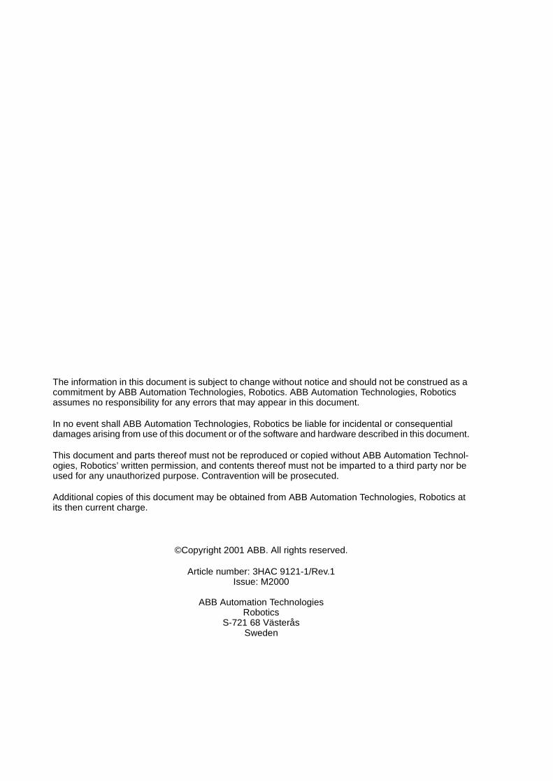
IRB 6400S
Figure 2 View of the manipulator from the side and rear (dimensions in mm).The robot is shown in its calibration position.
400
1705
200
1044
1031525 506
922
950
225165
1340
607
594
250
4 Product Specification IRB 6400S M2000

Description
1.2 Safety/Standards
The robot conforms to the following standards:
EN 292-1 Safety of machinery, terminology
EN 292-2 Safety of machinery, technical specifications
EN 954-1 Safety of machinery, safety related parts of control systems
EN 60204 Electrical equipment of industrial machines
IEC 204-1 Electrical equipment of industrial machines
ISO 10218, EN 775 Manipulating industrial robots, safety
ANSI/RIA 15.06/1999 Industrial robots, safety requirements
ISO 9409-1 Manipulating industrial robots, mechanical interface
ISO 9787 Manipulating industrial robots, coordinate systems and motions
IEC 529 Degrees of protection provided by enclosures
EN 50081-2 EMC, Generic emission
EN 50082-2 EMC, Generic immunity
ANSI/UL 1740-1996 (option) Standard for Industrial Robots and Robotic Equipment
CAN/CSA Z 434-94 (option) Industrial Robots and Robot Systems - General Safety Requirements
The robot complies fully with the health and safety standards specified in the EEC’s Machinery Directives.
The robot is designed with absolute safety in mind. It has a dedicated safety system based on a two-channel circuit which is monitored continuously. If any component fails, the electrical power supplied to the motors shuts off and the brakes engage.
Safety category 3Malfunction of a single component, such as a sticking relay, will be detected at the next MOTOR OFF/MOTOR ON operation. MOTOR ON is then prevented and the faulty section is indicated. This complies with category 3 of EN 954-1, Safety of machinery - safety related parts of control systems - Part 1.
Selecting the operating mode The robot can be operated either manually or automatically. In manual mode, the robot can only be operated via the teach pendant, i.e. not by any external equipment.
Reduced speedIn manual mode, the speed is limited to a maximum of 250 mm/s (600 inch/min.).The speed limitation applies not only to the TCP (Tool Centre point), but to all parts of the robot. It is also possible to monitor the speed of equipment mounted on the robot.
Three position enabling deviceThe enabling device on the teach pendant must be used to move the robot when in manual mode. The enabling device consists of a switch with three positions, meaning
Product Specification IRB 6400S M2000 5
Description
that all robot movements stop when either the enabling device is pushed fully in, or when it is released completely. This makes the robot safer to operate.
Safe manual movementThe robot is moved using a joystick instead of the operator having to look at the teach pendant to find the right key.
Over-speed protectionThe speed of the robot is monitored by two independent computers.
Emergency stopThere is one emergency stop push button on the controller and another on the teach pendant. Additional emergency stop buttons can be connected to the robot’s safety chain circuit.
Safeguarded space stopThe robot has a number of electrical inputs which can be used to connect external safety equipment, such as safety gates and light curtains. This allows the robot’s safety functions to be activated both by peripheral equipment and by the robot itself.
Delayed safeguarded space stopA delayed stop gives a smooth stop. The robot stops in the same way as at a normal program stop with no deviation from the programmed path. After approx. 1 second the power supplied to the motors shuts off.
Collision detection (option)In case an unexpected mechanical disturbance like a collision, electrode stik etc appears, the robot will stop and slightly back off from its stop position.
Restricting the working space The movement of each axis can be restricted using software limits. Axes 1-3 can also be restricted by means of mechanical stops (option).
Hold-to-run control“Hold-to-run” means that you must depress the start button in order to move the robot. When the button is released the robot will stop. The hold-to-run function makes program testing safer.
Fire safetyBoth the manipulator and control system comply with UL’s (Underwriters Laboratory) tough requirements for fire safety.
Safety lamp (option)As an option, the robot can be equipped with a safety lamp mounted on the manipulator. This is activated when the motors are in the MOTORS ON state.
6 Product Specification IRB 6400S M2000

Description
1.3 Installation
The IRB 6400S is designed for shelf-mounting. An end effector of max. weight 120 kg, including payload, can be mounted on the mounting flange (axis 6). See load diagram on page 9.
Extra loads (valve packages, transformers) can be mounted on the upper arm and extra load can also be mounted on the frame of axis 1. Holes for mounting extra equipment see page 11.
The working range of axes 1-3 can be limited by mechanical stops. Position switches can be supplied on axis 1 and axis 2 for position indication of the manipulator.
Operating requirements
Protection standards IEC529
IRB 6400S Manipulator IP54Wrist IP55
IRB 6400FS Manipulator IP55Upper arm IP66Wrist IP67
Explosive environmentsThe robot must not be located or operated in an explosive environment.
Ambient temperatureManipulator during operation +5oC (41oF) to +45oC (117oF)Complete robot during transportation and storage, -25oC (13oF) to +55oC (131oF)for short periods (not exceeding 24 hours) up to +70oC (158oF)
Relative humidityComplete robot during transportation and storage Max. 95% at constant temperatureComplete robot during operation Max. 95% at constant temperature
Product Specification IRB 6400S M2000 7

Description
Mounting the manipulator
Maximum load in relation to the base coordinate system.
Endurance load Max. load at in operation emergency stop
Force xy ± 12000 N ± 18000 NForce z 21000 ± 5500 N 21000 ± 10000 N
Torque xy ± 32000 Nm ± 39000 NmTorque z ± 6000 Nm ± 13000 Nm
Figure 3 Hole configuration (dimensions in mm).
Support surface D=85 (3x)
A
0.2 720
480 ±0.1
A
∅
415.
7
D=32 (3x)D=48 (3x)
D=64 H9 (3x)
A - A
X
Y
Z
100 ±0,5
15+2
0
(3x)
8 Product Specification IRB 6400S M2000
Description
Load diagram
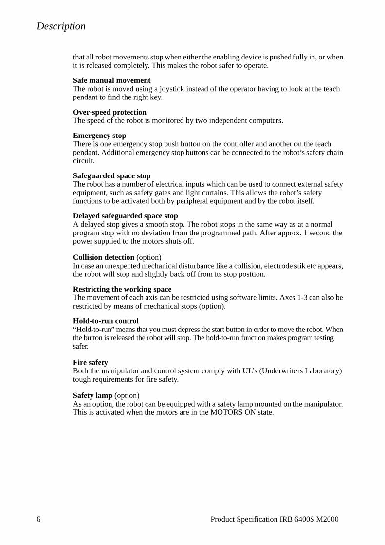
Figure 4 Maximum weight permitted for load mounted on the mounting flange at different positions (centre of gravity).
Z (m)
L (m)0.1 0.2 0.3
0.1
0.2
0.3
0.4
0.5
0.6
0.7
0.4 0.5 0.6 0.7
30 kg
45 kg
60 kg
100 kg
75 kg
120 kg
0.8
0.9
The load diagram is valid for J0 <100 kgm2.J0 = the maximum component (JX0, JY0, JZ0) of the moment of inertia of the handling weight at its centre of gravity.
Product Specification IRB 6400S M2000 9
Description
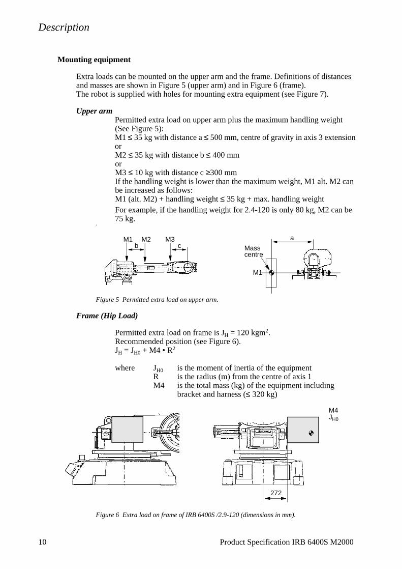
Mounting equipment
Extra loads can be mounted on the upper arm and the frame. Definitions of distances and masses are shown in Figure 5 (upper arm) and in Figure 6 (frame).The robot is supplied with holes for mounting extra equipment (see Figure 7).
Upper armPermitted extra load on upper arm plus the maximum handling weight (See Figure 5):M1 ≤ 35 kg with distance a ≤ 500 mm, centre of gravity in axis 3 extensionorM2 ≤ 35 kg with distance b ≤ 400 mmorM3 ≤ 10 kg with distance c ≥300 mmIf the handling weight is lower than the maximum weight, M1 alt. M2 can be increased as follows:M1 (alt. M2) + handling weight ≤ 35 kg + max. handling weightFor example, if the handling weight for 2.4-120 is only 80 kg, M2 can be 75 kg.
/
Figure 5 Permitted extra load on upper arm.
Frame (Hip Load)
Permitted extra load on frame is JH = 120 kgm2.Recommended position (see Figure 6).JH = JH0 + M4 • R2
where JH0 is the moment of inertia of the equipmentR is the radius (m) from the centre of axis 1 M4 is the total mass (kg) of the equipment including
bracket and harness (≤ 320 kg)
Figure 6 Extra load on frame of IRB 6400S /2.9-120 (dimensions in mm).
Masscentre
ab c
M1
M2 M3M1
M4JH0
272
10 Product Specification IRB 6400S M2000

Description
Product Specification IRB 6400S M2000 11
Holes for mounting extra equipment
Figure 7 Holes for mounting extra equipment (dimensions in mm).
A - A
AAD
D
B B
B - B
D - D
C C
E
E
E - E
175 810 (/2.4-x)
50
M10 (4x)
M10 (2x)282
93
260 M10 (4x) Depth 20
75150
200 M10 (2x)
175180
M10 (2x) See E-E
∅ 40/M12 (4x) Depth 20(on both sides)
59479
220
110
607
24
104 for “Hole 1”
C - C
80
M10 (2x) 378
F
F
93 for “Hole 2”See E-E
“Hole 1” “Hole 2”
112
15

Description
12 Product Specification IRB 6400S M2000
Figure 8 The mechanical interface (mounting flange) ISO 9409-1-A125 (dimensions in mm).
As an option there is an electrically insulated tool flange.For more information see Figure 12.
1.4 Maintenance and Troubleshooting
The robot requires only a minimum of maintenance during operation. It has been designed to make it as easy to service as possible:
- Maintenance-free AC motors are used.
- Liquid grease or oil is used for the gear boxes.
- The cabling is routed for longevity, and in the unlikely event of a failure, its modular design makes it easy to change.
The following maintenance is required:
- Changing grease and oil every third year.
- Changing batteries every third year.
- Some additional checks every year.
The maintenance intervals depends on the use of the robot. For detailed information on maintenance procedures, see Maintenance section in the Product Manual.
D=
160
h7
D=
80 H
7
8
8
30o
60o
D=10 H7 depth 10
M10 (6x) depth 18
D=125
F - F

Description
1.5 Robot Motion
Type of motion Range of movement
Axis 1 Rotation motion +180o to -180o Axis 2 Arm motion +140o to +10o Axis 3 Arm motion +155o to +47o Axis 4 Wrist motion +300o to -300o
Axis 5 Bend motion +120o to -120o Axis 6 Turn motion +300o to -300o
Figure 9 The extreme positions of the robot arm.
pos. axis 2 (ϕ2) axis 3(ϕ3)
0123456
60101090
140140112
604775
1551557547
Min. 25o Max. 155o 90o at pos. 0
Angle ϕ2, ϕ3 (degrees)
Angle 2/3 (ϕ2/ϕ3)
pos. x
0123456
246420861418
94-24518632802
Positions at wrist centre (mm)
z
-282449-46
-317-1045-1709-842
All dimensions refer to the wrist centre (mm)
1
2
3
4
5
6
0
2871
1840
ϕ2
ϕ3Z
X
ϕ2/ϕ3
Product Specification IRB 6400S M2000 13

Description
Performance according to ISO 9283
At rated load and 1 m/s velocity on the inclined ISO test plane with all six robot axes in motion.
Unidirectional pose repeatability: RP = 0.2 mm
Linear path accuracy: AT = 2.5 - 3.0 mm
Linear path repeatability:RT = 0.8 - 1.4 mm
Minimum positioning time, to within 0.4 mm of the position:0.3 - 0.5 sec. (on 35 mm linear path)0.7 - 0.9 sec. (on 350 mm linear path)
The above values are the range of average test-results from a number of robots. If guaranteed values are required, please contact your nearest ABB Flexible Automation Centre.
Velocity
Axis no. 1 100o/s2 100o/s3 100o/s4 210o/s5 150o/s6 210o/s
There is a supervision function to prevent overheating in applications with intensive and frequent movements.
Resolution
Approx. 0.01o on each axis.
1.6 Signals
Signal connections on robot arm
For connection of extra equipment on the manipulator there are cables integrated into the manipulator’s cabling, and two connectors, one FCI UT07 1412SH44N and one FCI UT07 1823SH44N, on the moveable part of the upper arm.
Signals 23 50 V, 250 mAPower 10 250 V, 2 AAir 1 Max. 10 bar, inner hose diameter 11 mm
14 Product Specification IRB 6400S M2000

Specification of Variants and Options
2 Specification of Variants and Options
The different variants and options for the IRB 6400S are described below.The same numbers are used here as in the Specification form. For controller options, see Product Specification S4Cplus, and for software options, see Product Specification RobotWare Options.
1 MANIPULATOR
VARIANTS
Standard Foundry (requires option 287-4) (requires option 287-3)
435-25 IRB 6400S IRB 6400FS
IRB 6400S Application, Mounting / Reach-Handling capacity
Application: F Robot adapted for foundry environments. Degree of protection as in Chapter 3.4. The manipulator is specially painted and finished.
Reach: Specifies the max. reach at the wrist centre.Handling capacity: Specifies the max. handling capacity.
Manipulator colour
209-1 ABB standardThe manipulator is painted with ABB orange.
209- RAL code4--192 The manipulator is painted with chosen RAL-colour.
Protection
287-4 Standard
287-3 FoundryRobot adapted for foundry environments. Degree of protection as in Chapter 1.3. The manipulator is specially painted and finished. Only available colour is ABB orange Foundry.
Product Specification IRB 6400S M2000 15

Specification of Variants and Options
APPLICATION INTERFACE
Air supply and signals for extra equipment to upper arm
218-6 Integrated hose for compressed air. There is an inlet at the base and an outlet on the upper arm (see Figure 10). Connections: R1/2”.
For connection of extra equipment on the manipulator there are cables integrated into the manipulator’s cabling, and two connectors, one FCI UT07 1412SH44N and one FCI UT07 1823SH44N, on the moveable part of the upper arm.
This option is standard on IRB 6400FS.
Figure 10 Connection of signals on the upper arm.
Connection of signals to
16-2 ManipulatorThe signals are connected directly to the robot base to one Harting 40-pin connector . The cables from the manipulator base are not supplied.
16-1 CabinetThe signals are connected to 12-pole screw terminals, Phoenix MSTB 2.5/12-ST-5.08, in the controller.The cable between R1.CP/CS and the controller is supplied.
Connection to cabinet (Cable lengths)
94-1 7m94-2 15m94-3 22m94-4 30m
EQUIPMENT
213-1 Safety lampA safety lamp with an orange fixed light can be mounted on the manipulator.The lamp is active in MOTORS ON mode.The safety lamp is required on a UL/UR approved robot.
118-1 DressingMounting of extra equipment, e.g. tool system on robot before delivery, ordered from ABB Flexible Automation/Department U.
159-1 Fork lift deviceLifting device on the manipulator for fork-lift handling is mounted at delivery.Lifting eyes for use with an overhead crane are integrated as standard.
042
16 Product Specification IRB 6400S M2000

Specification of Variants and Options
84-1 Cooling for axis 1 motorThe robot can be used for heavy duty applications on axis 1 if a cooling device is used on this axis, e.g. in press tending applications.This option is not intended for use in Foundry version.
Figure 11 Location of the fan on the manipulator.
50-1 Brake release coverProtective cover over push-buttons on brake release unit.Always included for Foundry versions.
184-1 Insulated flangeElectrically insulated tool flange. In case of an electrical fault in the spot welding equipment mounted on the tool flange, the tool flange withstands dangerous voltage (100V AC during 60 seconds or 300V AC during 10 seconds) in non-water applications without passing it further to electronics in the robot and controller.See Figure 12.This option is not intended for use in Foundry version.
Figure 12 The mechanical interface of the insulated flange (dimensions in mm).
POSITION SWITCHES (not available for IRB 6400FS)
Position switches indicating the position of axis 1. Rails with separate adjustable cams are attached to the manipulator. The cams, which have to be adapted to the switch function by the user, can be mounted in any position in the working range for each switch.
Fan
30o
60o
D=10 H7 Depth 10
M10 (6x) Depth 18
D=
160
h7
D=
80 H
7
D=125
8
810oD=10 H7 Depth 10
Product Specification IRB 6400S M2000 17

Specification of Variants and Options
The position switch device is delivered as a kit to be assembled when installing the robot. Assembly instruction is included.
Note! This option may require external safety arrangements, e.g. light curtains, photocells or contact mats.
Note The switches are not recommended to be used in severe environment with sand or chips.
1, 2 or 3 switches indicating the position of axis 1.Switch type: Telemecanique XCK-M1/ZCK-D16, 2 pole N/C + N/O, according to IEC 947-5-1.
25-2 1 switch
25-4 2 switches
25-3 3 switches
Connection to
271-2 ManipulatorConnection on the manipulator base with one FCI 23-pin connector.
271-1 CabinetConnection on the cabinet wall. Position switch cables are included.The signals are connected to 12-pole screw terminals, Phoenix MSTB 2.5/12-ST-5.08
Connection of signals (Cable lengths)
273-1 7m273-2 15m273-3 22m273-4 30m
WORKING RANGE LIMITTo increase the safety of the robot, the working range of axes 1, 2 and 3 can be restricted by extra mechanical stops.
28-1 Axis 12 stops which allow the working range to be restricted in any increment of 20o.
32-1 Axis 2 6 stops which allow the working range to be restricted in increments of 20o. Each stop decreases the motion by 20°. This means that the motion can be decreased by 6 x 20° from the maximum axis motion.
34-1 Axis 36 stops which allow the working range to be restricted in increments of 20o. Each stop decreases the motion by 20°. This means that the motion can be decreased by 6 x 20° from the maximum axis motion.
18 Product Specification IRB 6400S M2000
Accessories
3 Accessories
There is a range of tools and equipment available, specially designed for the robot.
Basic software and software options for robot and PC
For more information, see Product Specification S4Cplus, and Product Specification RobotWare Options.
Robot Peripherals
- Track Motion
- Tool System
- Motor Units
- Spot welding system for transformer gun
Product Specification IRB 6400S M2000 19

Accessories
20 Product Specification IRB 6400S M2000

Index
4 Index
A
accessories 19air supply 16
B
brake release cover 17
C
cooling device 3
E
emergency stop 6enabling device 5equipment
mounting 10permitted extra load 10
extra equipmentconnections 16
F
fire safety 6fork lift device 16
H
hold-to-run control 6humidity 7
I
installation 7Insulated flange 17
L
lifting device 16load 7, 8load diagrams 9
M
maintenance 12mechanical interface 12motion 13mounting
extra equipment 10
Product Specification IRB 6400S M2000
21robot 8mounting flange 12
N
noise level 3
O
operating requirements 7options 15overspeed protection 6
P
payload 7performance 14position switch 17protection standards 7
R
reduced speed 5repeatability 14Robot Peripherals 19
S
safeguarded space stop 6delayed 6
safety 5Safety lamp 6safety lamp 16service 12service position indicator 17signal connections 16space requirements 3standards 5structure 3
T
temperature 7troubleshooting 12
V
variants 15
W
working spacerestricting 6, 7, 18

Index
2
2 Product Specification IRB 6400S M2000