product specification - irb 660 -...
TRANSCRIPT
Product specificationIRB 660

Trace back information:Workspace R14-1 version a5Checked in 2014-04-07Skribenta version 4.0.378

Product specificationIRB 660-180/3.15IRB 660-250/3.15
Document ID: 3HAC023932-001Revision: P
© Copyright 2004-2014 ABB. All rights reserved.
The information in this manual is subject to change without notice and should notbe construed as a commitment by ABB. ABB assumes no responsibility for any errorsthat may appear in this manual.Except as may be expressly stated anywhere in this manual, nothing herein shall beconstrued as any kind of guarantee or warranty by ABB for losses, damages topersons or property, fitness for a specific purpose or the like.In no event shall ABB be liable for incidental or consequential damages arising fromuse of this manual and products described herein.This manual and parts thereof must not be reproduced or copied without ABB'swritten permission.Additional copies of this manual may be obtained from ABB.The original language for this publication is English. Any other languages that aresupplied have been translated from English.
© Copyright 2004-2014 ABB. All rights reserved.ABB AB
Robotics ProductsSe-721 68 Västerås
Sweden
Table of contents7Overview of this specification ..........................................................................................................9Overview ...........................................................................................................................................
111 Description111.1 Structure .........................................................................................................111.1.1 Introduction ............................................................................................131.1.2 Different robot versions ............................................................................141.1.3 Definition of version designation ................................................................171.2 Standards ........................................................................................................171.2.1 Applicable safety standards ......................................................................191.3 Installation .......................................................................................................191.3.1 Introduction ............................................................................................201.3.2 Operating requirements ............................................................................211.3.3 Mounting the manipulator .........................................................................261.4 Calibration .......................................................................................................261.4.1 Fine calibration .......................................................................................271.5 Load diagrams ..................................................................................................271.5.1 Introduction to Load diagrams ...................................................................281.5.2 Load diagrams ........................................................................................301.5.3 Maximum load and moment of inertia ..........................................................311.6 Mounting of equipment .......................................................................................311.6.1 Overview ...............................................................................................351.7 Robot motion ....................................................................................................351.7.1 Introduction ............................................................................................371.7.2 Performance according to ISO 9283 ............................................................381.7.3 Velocity .................................................................................................391.7.4 Stopping distance/time .............................................................................401.8 Customer connections .......................................................................................401.8.1 Introduction ............................................................................................411.9 Maintenance and troubleshooting .........................................................................411.9.1 Introduction ............................................................................................
432 Specification of variants and options432.1 Introduction to variants and options ......................................................................442.2 Manipulator ......................................................................................................462.3 Floor cables .....................................................................................................472.4 Process ...........................................................................................................482.5 Documentation .................................................................................................
493 Accessories493.1 Introduction to accessories .................................................................................
51Index
3HAC023932-001 Revision: P 5© Copyright 2004-2014 ABB. All rights reserved.
Table of contents

This page is intentionally left blank
Overview of this specificationAbout this Product specification
It describes the performance of themanipulator or a complete family of manipulatorsin terms of:
• The structure and dimensional prints• The fulfilment of standards, safety and operating requirements• The load diagrams, mounting of extra equipment, the motion and the robot
reach• The specification of variant and options available
UsageProduct specifications are used to find data and performance about the product,for example to decide which product to buy. How to handle the product is describedin the product manual.
Who should read this manual?This manual is intended for:
• Product managers and Product personnel• Sales and Marketing personnel• Order and Customer Service personnel
References
Document IDReference
3HAC041344-001Product specification - Controller IRC5 with FlexPendant
3HAC022349-001Product specification - Controller software IRC5
3HAC024534-001Product specification - Robot user documentation
3HAC025755-001Product manual - IRB 660
Revisions
DescriptionRevision
- New Product specification-
- General correctionsA
- Changes in Figure 3 and Figure 16.B
- Update Customer connections- Interbus removedC- Footnote added to “Pose accuracy”- Stock Warranty
- Changes in chapter StandardsD- Directions of forces- Warranty information for Load diagrams
- Position switches removed.E
Continues on next page3HAC023932-001 Revision: P 7
© Copyright 2004-2014 ABB. All rights reserved.
Overview of this specification
DescriptionRevision
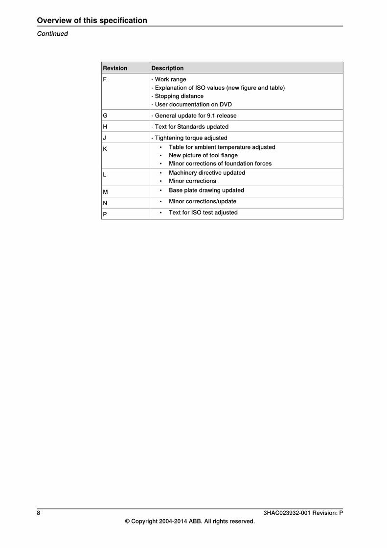
- Work rangeF- Explanation of ISO values (new figure and table)- Stopping distance- User documentation on DVD
- General update for 9.1 releaseG
- Text for Standards updatedH
- Tightening torque adjustedJ• Table for ambient temperature adjusted• New picture of tool flange• Minor corrections of foundation forces
K
• Machinery directive updated• Minor corrections
L
• Base plate drawing updatedM• Minor corrections/updateN• Text for ISO test adjustedP
8 3HAC023932-001 Revision: P© Copyright 2004-2014 ABB. All rights reserved.
Overview of this specificationContinued

OverviewAbout this Product specification
It describes the performance of themanipulator or a complete family of manipulatorsin terms of:
• The structure and dimensional prints• The fulfilment of standards, safety and operating requirements• The load diagrams, mounting of extra equipment, the motion and the robot
reach• The specification of variant and options available
UsageProduct specifications are used to find data and performance about the product,for example to decide which product to buy. How to handle the product is describedin the product manual.
Who should read this manual?This manual is intended for:
• Product managers and Product personnel• Sales and Marketing personnel• Order and Customer Service personnel
ContentsPlease see Table of Contents on page 3.
References
Document IDReference
3HAC041344-001Product specification - Controller IRC5 with FlexPendant
3HAC022349-001Product specification - Controller software IRC5
3HAC024534-001Product specification - Robot user documentation
3HAC025755-001Product manual - IRB 660
Revisions
DescriptionRevision
- New Product specification-
- General correctionsA
- Changes in Figure 3 and Figure 16.B
- Update Customer connections- Interbus removedC- Footnote added to “Pose accuracy”- Stock Warranty
- Changes in chapter StandardsD- Directions of forces- Warranty information for Load diagrams
Continues on next page3HAC023932-001 Revision: P 9
© Copyright 2004-2014 ABB. All rights reserved.
Overview

DescriptionRevision
- Position switches removed.E
- Work rangeF- Explanation of ISO values (new figure and table)- Stopping distance- User documentation on DVD
- General update for 9.1 releaseG
- Text for Standards updatedH
- Tightening torque adjustedJ• Table for ambient temperature adjusted• New picture of tool flange• Minor corrections of foundation forces
K
• Machinery directive updated• Minor corrections
L
• Base plate drawing updatedM• Minor corrections/updateN• Text for ISO test adjustedP
10 3HAC023932-001 Revision: P© Copyright 2004-2014 ABB. All rights reserved.
OverviewContinued
1 Description1.1 Structure
1.1.1 Introduction
Robot familyIRB 660 is ABB Robotics latest generation of 4-axis palletizing robot, designedwith a focus on its high production capacity, short cycle time at a high payload,long reach together with the very high uptime, which is significant for ABB’s robots.It is available in two versions; a handling capacity of 180 kg and 250 kg, both witha reach of 3.15 m.Customer connections such as power signals, Bus signals and twin air areintegrated in the robot, from the robot base to connections at the robot tool flange.
Operating systemThe robot is equipped with the IRC5 controller and robot control software,RobotWare. RobotWare supports every aspect of the robot system, such asmotioncontrol, development and execution of application programs, communication andso on. For more information, see Product specification - Controller IRC5 withFlexPendant.
SafetySafety standards valid for complete robot, manipulator and controller.
Additional functionalityFor additional functionality, the robot can be equipped with optional software forapplication support. For example, gluing and welding, communication feature suchas network communication, and advanced functions such as multitasking, sensorcontrol and so on. For a complete description on optional software, see Productspecification - Controller software IRC5.
Continues on next page3HAC023932-001 Revision: P 11
© Copyright 2004-2014 ABB. All rights reserved.
1 Description1.1.1 Introduction
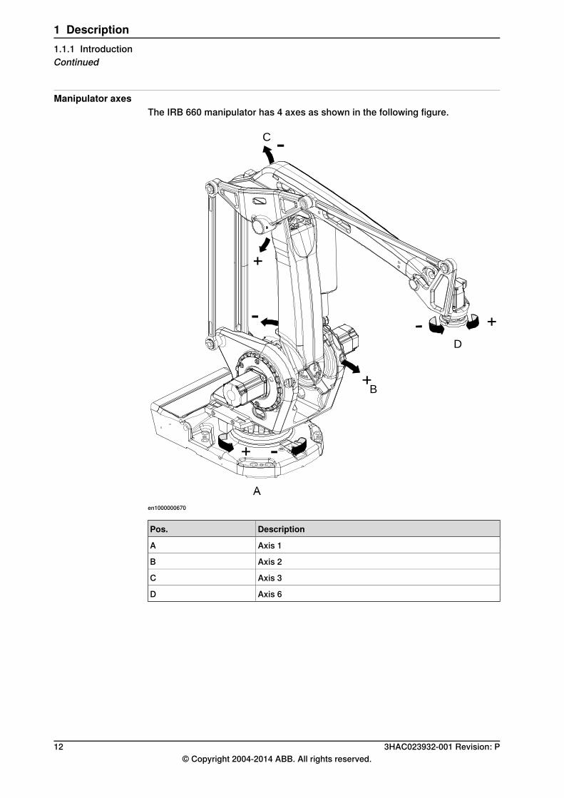
Manipulator axesThe IRB 660 manipulator has 4 axes as shown in the following figure.
B
D
C
en1000000670
DescriptionPos.
Axis 1A
Axis 2B
Axis 3C
Axis 6D
12 3HAC023932-001 Revision: P© Copyright 2004-2014 ABB. All rights reserved.
1 Description1.1.1 IntroductionContinued

1.1.2 Different robot versions
GeneralThe IRB 660 is available in two versions.
Reach (m)Handling capacity (kg)Robot type
3.15180IRB 660
3.15250IRB 660
3HAC023932-001 Revision: P 13© Copyright 2004-2014 ABB. All rights reserved.
1 Description1.1.2 Different robot versions
1.1.3 Definition of version designation
IRB 660 MountingHandling capacity/ Reach
DescriptionPrefix
Floor-mounted manipulator-Mounting
Indicates the maximum handling capacity (kg)yyyHandling capacity
Indicates the maximum reach at wrist center (m)x.xReach
Manipulator weight
Weight (kg)Reach (m)Handling capacity (kg)Robot type
17503.15180IRB 660
17503.15250IRB 660
Other technical data
NoteDescriptionData
< 70 dB (A) Leq (acc. to Ma-chiney directive 2006/42/EG).
The sound pressure leveloutside the working space
Airborne noise level
Continues on next page14 3HAC023932-001 Revision: P
© Copyright 2004-2014 ABB. All rights reserved.
1 Description1.1.3 Definition of version designation
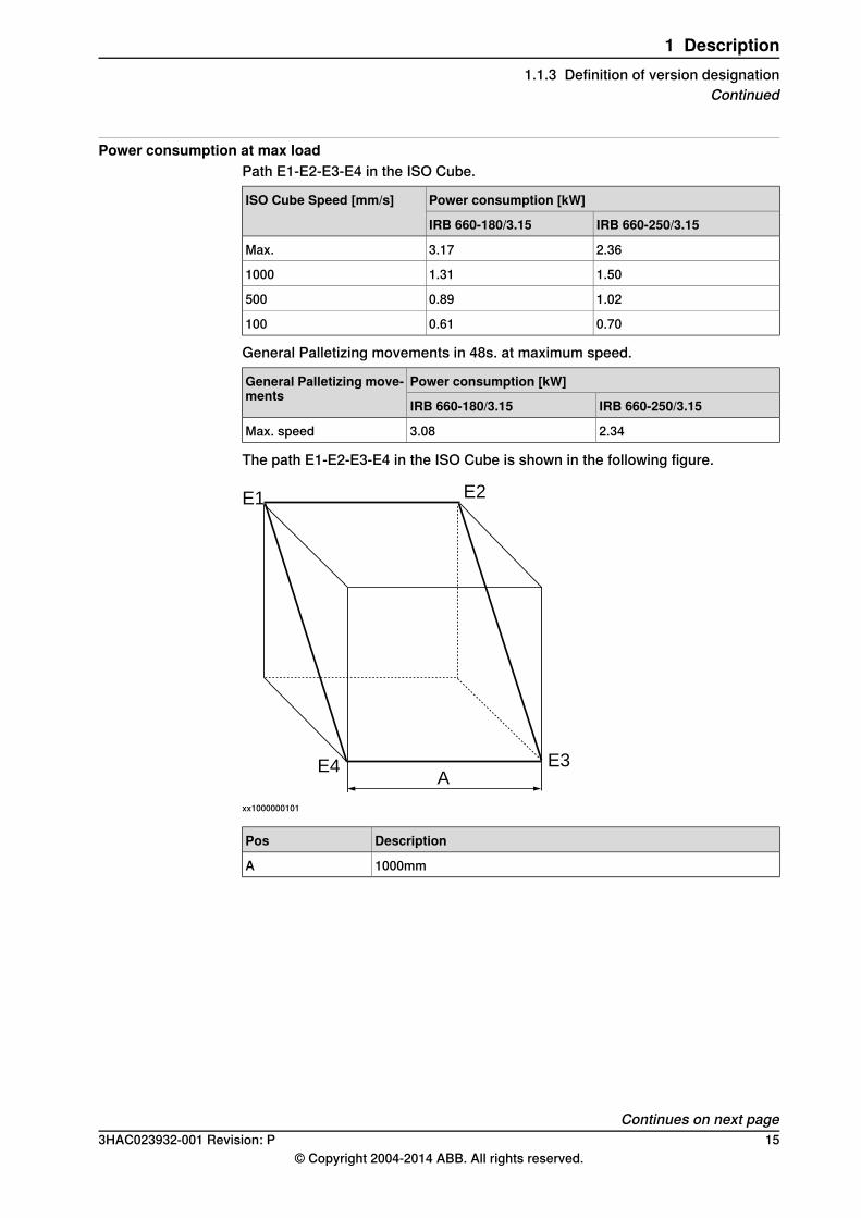
Power consumption at max loadPath E1-E2-E3-E4 in the ISO Cube.
Power consumption [kW]ISO Cube Speed [mm/s]
IRB 660-250/3.15IRB 660-180/3.15
2.363.17Max.
1.501.311000
1.020.89500
0.700.61100
General Palletizing movements in 48s. at maximum speed.
Power consumption [kW]General Palletizing move-ments
IRB 660-250/3.15IRB 660-180/3.15
2.343.08Max. speed
The path E1-E2-E3-E4 in the ISO Cube is shown in the following figure.
E1
E4 E3
E2
A
xx1000000101
DescriptionPos
1000mmA
Continues on next page3HAC023932-001 Revision: P 15
© Copyright 2004-2014 ABB. All rights reserved.
1 Description1.1.3 Definition of version designation
Continued
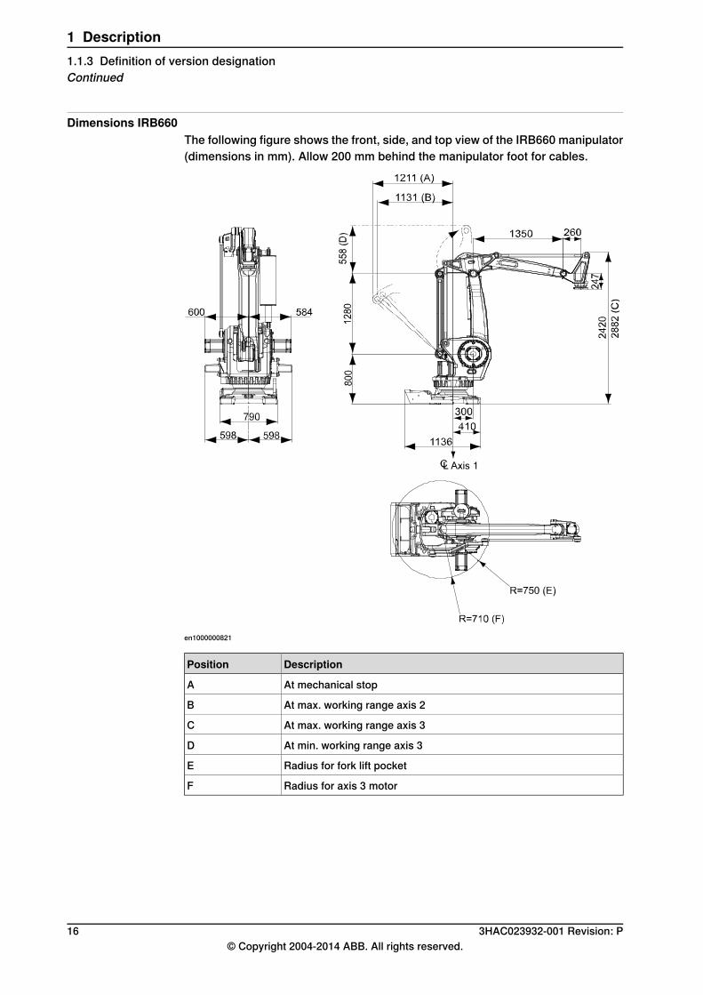
Dimensions IRB660The following figure shows the front, side, and top view of the IRB660 manipulator(dimensions in mm). Allow 200 mm behind the manipulator foot for cables.
en1000000821
DescriptionPosition
At mechanical stopA
At max. working range axis 2B
At max. working range axis 3C
At min. working range axis 3D
Radius for fork lift pocketE
Radius for axis 3 motorF
16 3HAC023932-001 Revision: P© Copyright 2004-2014 ABB. All rights reserved.
1 Description1.1.3 Definition of version designationContinued
1.2 Standards
1.2.1 Applicable safety standards
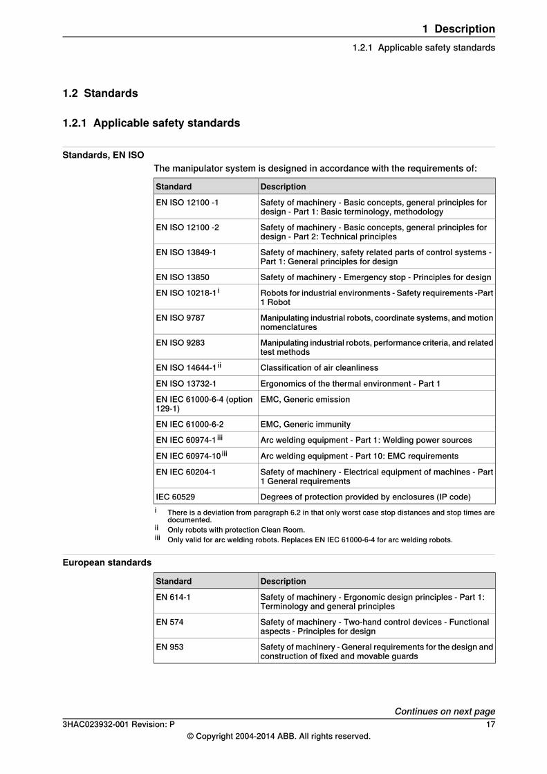
Standards, EN ISOThe manipulator system is designed in accordance with the requirements of:
DescriptionStandard
Safety of machinery - Basic concepts, general principles fordesign - Part 1: Basic terminology, methodology
EN ISO 12100 -1
Safety of machinery - Basic concepts, general principles fordesign - Part 2: Technical principles
EN ISO 12100 -2
Safety of machinery, safety related parts of control systems -Part 1: General principles for design
EN ISO 13849-1
Safety of machinery - Emergency stop - Principles for designEN ISO 13850
Robots for industrial environments - Safety requirements -Part1 Robot
EN ISO 10218-1 i
Manipulating industrial robots, coordinate systems, andmotionnomenclatures
EN ISO 9787
Manipulating industrial robots, performance criteria, and relatedtest methods
EN ISO 9283
Classification of air cleanlinessEN ISO 14644-1 ii
Ergonomics of the thermal environment - Part 1EN ISO 13732-1
EMC, Generic emissionEN IEC 61000-6-4 (option129-1)
EMC, Generic immunityEN IEC 61000-6-2
Arc welding equipment - Part 1: Welding power sourcesEN IEC 60974-1 iii
Arc welding equipment - Part 10: EMC requirementsEN IEC 60974-10 iii
Safety of machinery - Electrical equipment of machines - Part1 General requirements
EN IEC 60204-1
Degrees of protection provided by enclosures (IP code)IEC 60529i There is a deviation from paragraph 6.2 in that only worst case stop distances and stop times are
documented.ii Only robots with protection Clean Room.iii Only valid for arc welding robots. Replaces EN IEC 61000-6-4 for arc welding robots.
European standards
DescriptionStandard
Safety of machinery - Ergonomic design principles - Part 1:Terminology and general principles
EN 614-1
Safety of machinery - Two-hand control devices - Functionalaspects - Principles for design
EN 574
Safety of machinery - General requirements for the design andconstruction of fixed and movable guards
EN 953
Continues on next page3HAC023932-001 Revision: P 17
© Copyright 2004-2014 ABB. All rights reserved.
1 Description1.2.1 Applicable safety standards
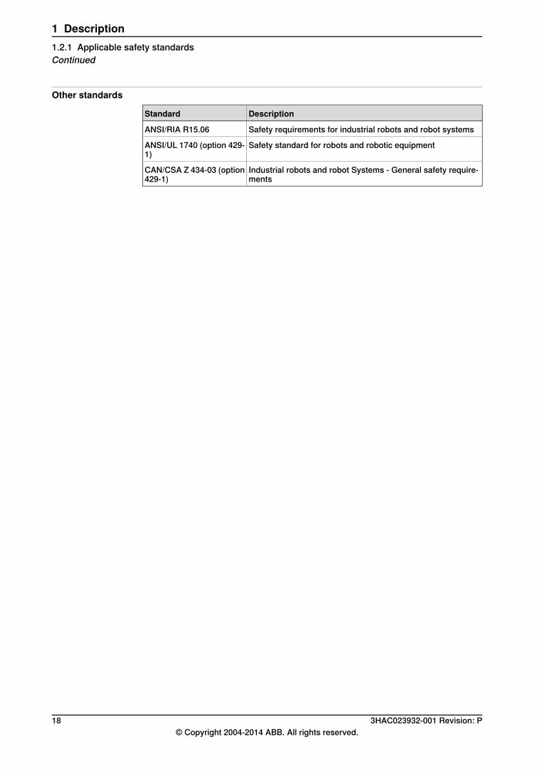
Other standards
DescriptionStandard
Safety requirements for industrial robots and robot systemsANSI/RIA R15.06
Safety standard for robots and robotic equipmentANSI/UL 1740 (option 429-1)
Industrial robots and robot Systems - General safety require-ments
CAN/CSA Z 434-03 (option429-1)
18 3HAC023932-001 Revision: P© Copyright 2004-2014 ABB. All rights reserved.
1 Description1.2.1 Applicable safety standardsContinued
1.3 Installation
1.3.1 Introduction
GeneralIRB 660 is designed for floor mounting. Depending on the robot version, an endeffector with maximum weight of 180 to 250 kg including payload, can be mountedon the mounting flange (axis 6). For more information on Load diagrams, see Loaddiagrams on page 28.
Working RangeThe working range of axis 1 can be limited bymechanical stops. Electronic PositionSwitches can be used on all axes, for position indication of the manipulator.
External Mains TransformerInclude an external transformer for mains voltage 200V and 220V.
3HAC023932-001 Revision: P 19© Copyright 2004-2014 ABB. All rights reserved.
1 Description1.3.1 Introduction
1.3.2 Operating requirements
Protection standardsManipulator IP67.
Explosive environmentsThe robot must not be located or operated in an explosive environment.
Ambient temperature
TemperatureStandard/OptionDescription
0°C i (32°F) to +45°C (113°F)StandardManipulator during operation
See Product specification - ControllerIRC5 with FlexPendant
Standard/OptionFor the controller
-25°C (-13°F) to +55°C (131°F)StandardComplete robot during trans-portation and storage
up to +70°C (158°F)StandardFor short periods (not exceed-ing 24 hours).i At low environmental temperature < 10o C is, as with any other machine, a warm-up phase
recommended to be run with the robot. Below 5o C this warm-up phase is mandatory. Otherwisethere is a risk that the robot stops or run with lower performance due to temperature dependentoil and grease viscosity.
Relative humidity
Relative humidiyDescription
Maximum95%at constant temperat-ure
Complete robot during operation, transportation andstorage
20 3HAC023932-001 Revision: P© Copyright 2004-2014 ABB. All rights reserved.
1 Description1.3.2 Operating requirements
1.3.3 Mounting the manipulator
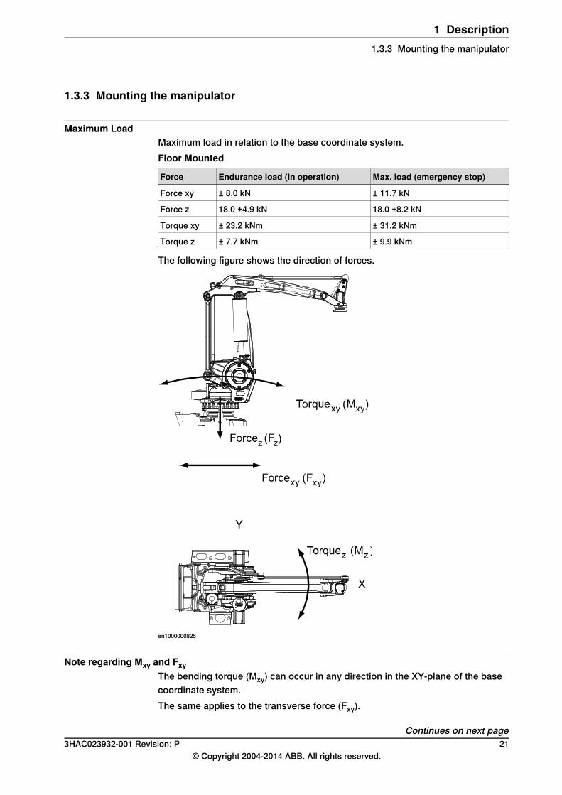
Maximum LoadMaximum load in relation to the base coordinate system.Floor Mounted
Max. load (emergency stop)Endurance load (in operation)Force
± 11.7 kN± 8.0 kNForce xy
18.0 ±8.2 kN18.0 ±4.9 kNForce z
± 31.2 kNm± 23.2 kNmTorque xy
± 9.9 kNm± 7.7 kNmTorque z
The following figure shows the direction of forces.
en1000000825
Note regarding Mxy and FxyThe bending torque (Mxy) can occur in any direction in the XY-plane of the basecoordinate system.The same applies to the transverse force (Fxy).
Continues on next page3HAC023932-001 Revision: P 21
© Copyright 2004-2014 ABB. All rights reserved.
1 Description1.3.3 Mounting the manipulator
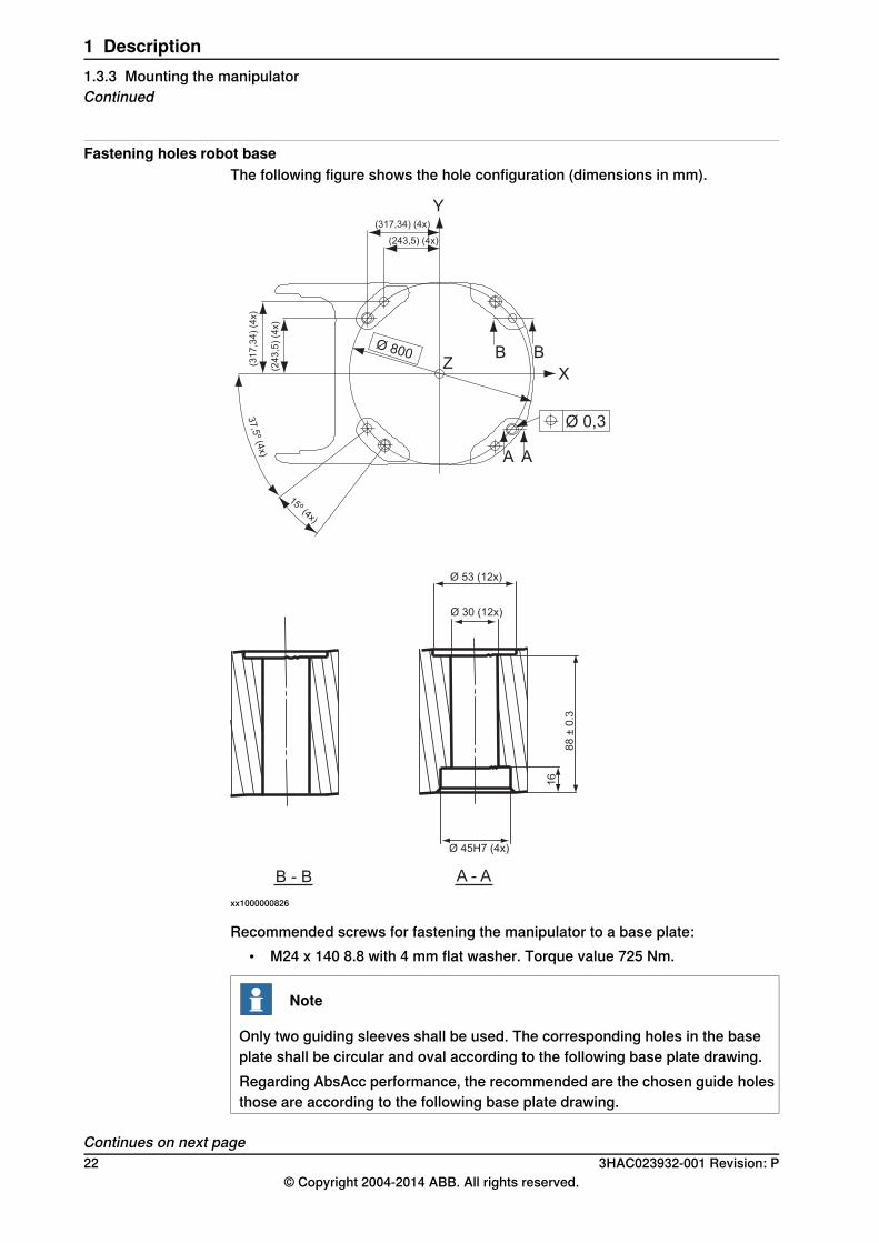
Fastening holes robot baseThe following figure shows the hole configuration (dimensions in mm).
B B
XZ
Ø 0,3
A A
15º (4x)
37,5
º (4x)
(31
7,3
4)
(4x)
(24
3,5
) (4
x)
Ø 800
(317,34) (4x)
(243,5) (4x)
Y
Ø 53 (12x)
Ø 30 (12x)
16
88
± 0
.3
Ø 45H7 (4x)
B - B A - A
xx1000000826
Recommended screws for fastening the manipulator to a base plate:• M24 x 140 8.8 with 4 mm flat washer. Torque value 725 Nm.
Note
Only two guiding sleeves shall be used. The corresponding holes in the baseplate shall be circular and oval according to the following base plate drawing.Regarding AbsAcc performance, the recommended are the chosen guide holesthose are according to the following base plate drawing.
Continues on next page22 3HAC023932-001 Revision: P
© Copyright 2004-2014 ABB. All rights reserved.
1 Description1.3.3 Mounting the manipulatorContinued
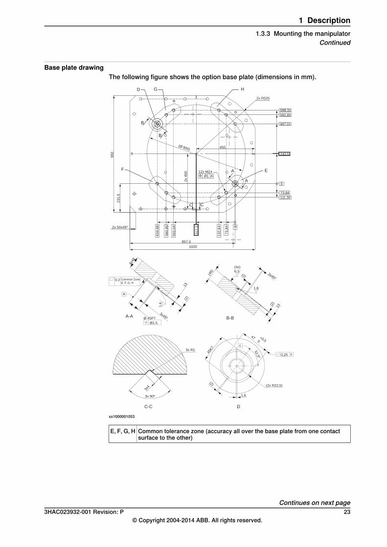
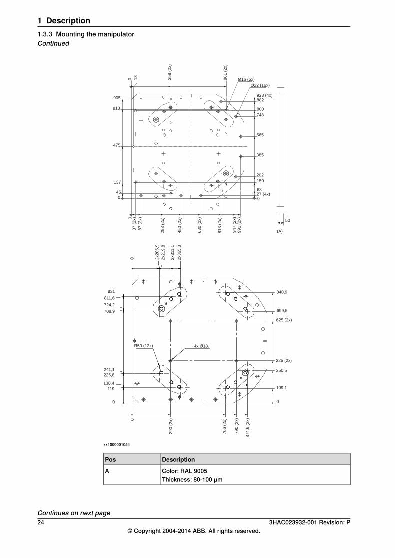
Base plate drawingThe following figure shows the option base plate (dimensions in mm).
A
A
B
B
C
D G H
EF
2x R525
598,31
560,85
487,01
243,5
0
73,84
111,30
1020
857,3
73,8
4
132,6
4
317,3
502,0
4
560,8
5
634,6
8 02x 50x45º
231,5
2x 4
50
950
(Ø 800)
12x M24
Ø1 A
455
C
A
4x48
13(2
)
1,6
3x45º
0.2
Ø 45P7A-A
Ø1.5
(4x)
6,3
(48)
(2)
1,6
3x45º
B-B
(2)
13
3x R1
3x4
3x 90º
C-C
45K7
+0,50
47
0,25 c
(2x R22,5)
1,6
D
(2)
c
52,5
º
Common Zone
E, F, G, H
xx1000001053
Common tolerance zone (accuracy all over the base plate from one contactsurface to the other)
E, F, G, H
Continues on next page3HAC023932-001 Revision: P 23
© Copyright 2004-2014 ABB. All rights reserved.
1 Description1.3.3 Mounting the manipulator
Continued
840,9
699,5
625 (2x)
325 (2x)
250,5
109,1
0
87
4,6
(2
x)
79
0 (
2x)
70
6 (
2x)
29
0 (
2x)0
0
119
138,4
241,1
225,8
R50 (12x) 4x Ø18.
2x2
06
,9
2x2
19
,8
2x3
11
,1
2x3
65
,3
0
831
811,6
724,2
708,9
50
027 (4x)68
150
202
385
565
748
800
882923 (4x)
Ø16 (5x)
Ø22 (16x)
86
1 (
2x)
35
8 (
2x)
18
0
905
813
475
137
45
0
03
7 (
2x)
87
(2
x)
29
3 (
2x)
45
0 (
2x)
63
0 (
2x)
81
3 (
2x)
94
7 (
2x)
99
1 (
2x)
(A)
xx1000001054
DescriptionPos
Color: RAL 9005AThickness: 80-100 µm
Continues on next page24 3HAC023932-001 Revision: P
© Copyright 2004-2014 ABB. All rights reserved.
1 Description1.3.3 Mounting the manipulatorContinued
xx1000001055
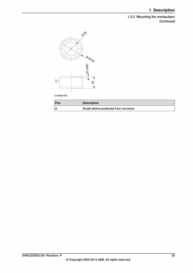
DescriptionPos
Guide sleeve protected from corrosionA
3HAC023932-001 Revision: P 25© Copyright 2004-2014 ABB. All rights reserved.
1 Description1.3.3 Mounting the manipulator
Continued
1.4 Calibration
1.4.1 Fine calibration
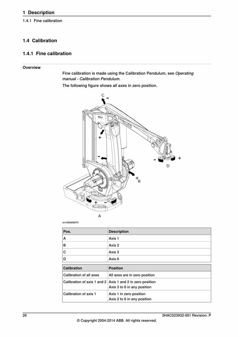
OverviewFine calibration is made using the Calibration Pendulum, see Operatingmanual - Calibration Pendulum.The following figure shows all axes in zero position.
B
D
C
en1000000670
DescriptionPos.
Axis 1A
Axis 2B
Axis 3C
Axis 6D
PositionCalibration
All axes are in zero positionCalibration of all axes
Axis 1 and 2 in zero positionCalibration of axis 1 and 2Axis 3 to 6 in any position
Axis 1 in zero positionCalibration of axis 1Axis 2 to 6 in any position
26 3HAC023932-001 Revision: P© Copyright 2004-2014 ABB. All rights reserved.
1 Description1.4.1 Fine calibration
1.5 Load diagrams
1.5.1 Introduction to Load diagrams
Information
WARNING
It is very important to always define correct actual load data and correct payloadof the robot. Incorrect definitions of load data can result in overloading of therobot.If incorrect load data and/or loads are outside load diagram is used the followingparts can be damaged due to overload:• motors• gearboxes• mechanical structure
WARNING
In the robot system is the service routine LoadIdentify available, which allowsthe user to make an automatic definition of the tool and load, to determine correctload parameters. Please seeOperating Manual - IRC5 with FlexPendant, art. No.3HAC16590-1, for detailed information.
WARNING
Robots running with incorrect load data and/or with loads outside diagram, willnot be covered by robot warranty.
GeneralThe load diagrams include a nominal payload inertia, J0 of 15 kgm2 , and an extraload of 50 kg at the upper arm housing.At different arm load, payload and moment of inertia, the load diagram will bechanged.
Control of load case by “RobotLoad”For an easy check of a specific load case, use the calculation program ABBRobotLoad. Please contact your local ABB organization.
3HAC023932-001 Revision: P 27© Copyright 2004-2014 ABB. All rights reserved.
1 Description1.5.1 Introduction to Load diagrams
1.5.2 Load diagrams
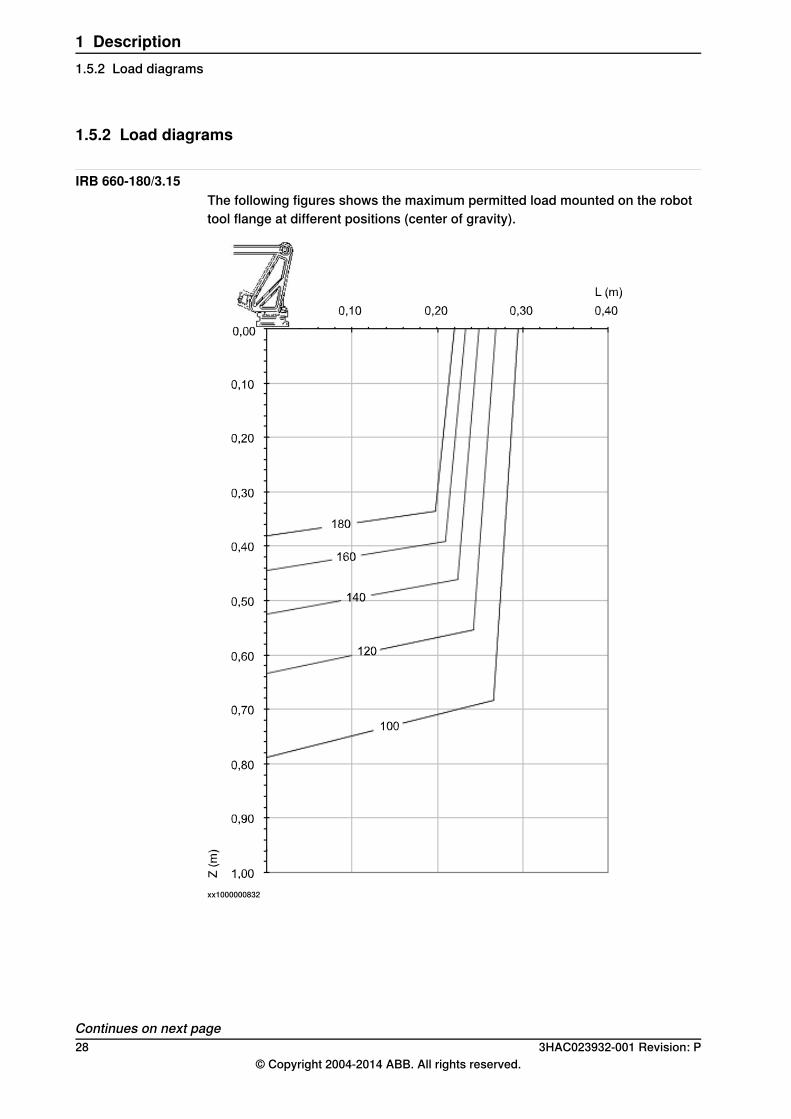
IRB 660-180/3.15The following figures shows the maximum permitted load mounted on the robottool flange at different positions (center of gravity).
xx1000000832
Continues on next page28 3HAC023932-001 Revision: P
© Copyright 2004-2014 ABB. All rights reserved.
1 Description1.5.2 Load diagrams
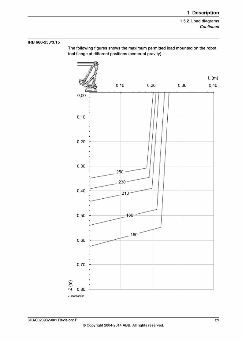
IRB 660-250/3.15The following figures shows the maximum permitted load mounted on the robottool flange at different positions (center of gravity).
xx1000000833
3HAC023932-001 Revision: P 29© Copyright 2004-2014 ABB. All rights reserved.
1 Description1.5.2 Load diagrams
Continued

1.5.3 Maximum load and moment of inertia
OverviewLoad in kg, Z and L in m and J in kgm2 .
Maximum moment of inertiaAxis
Ja6 = Load x L2 + J0Z≤ 250 kgm26
xx1000000834
DescriptionPos
Center of gravityA
Description
Max. moment of inertia around the X, Y and Z axes at center of gravity.Jox , Joy , Joz
30 3HAC023932-001 Revision: P© Copyright 2004-2014 ABB. All rights reserved.
1 Description1.5.3 Maximum load and moment of inertia
1.6 Mounting of equipment
1.6.1 Overview
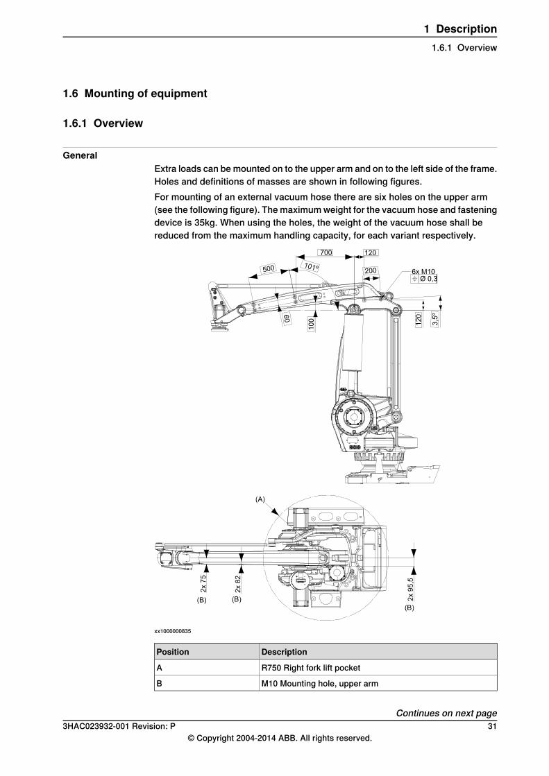
GeneralExtra loads can bemounted on to the upper arm and on to the left side of the frame.Holes and definitions of masses are shown in following figures.For mounting of an external vacuum hose there are six holes on the upper arm(see the following figure). Themaximumweight for the vacuum hose and fasteningdevice is 35kg. When using the holes, the weight of the vacuum hose shall bereduced from the maximum handling capacity, for each variant respectively.
xx1000000835
DescriptionPosition
R750 Right fork lift pocketA
M10 Mounting hole, upper armB
Continues on next page3HAC023932-001 Revision: P 31
© Copyright 2004-2014 ABB. All rights reserved.
1 Description1.6.1 Overview
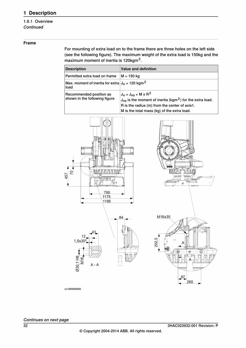
FrameFor mounting of extra load on to the frame there are three holes on the left side(see the following figure). The maximum weight of the extra load is 150kg and themaximum moment of inertia is 120kgm2 .
Value and definitionDescription
M = 150 kgPermitted extra load on frame
JH = 120 kgm2Max. moment of inertia for extraload
JH = JH0 + M x R2Recommended position asshown in the following figure JH0 is the moment of inertia (kgm2 ) for the extra load.
R is the radius (m) from the center of axis1.M is the total mass (kg) of the extra load.
xx1000000836
Continues on next page32 3HAC023932-001 Revision: P
© Copyright 2004-2014 ABB. All rights reserved.
1 Description1.6.1 OverviewContinued
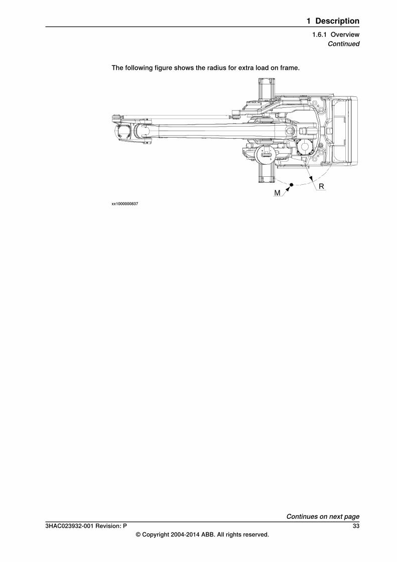
The following figure shows the radius for extra load on frame.
xx1000000837
Continues on next page3HAC023932-001 Revision: P 33
© Copyright 2004-2014 ABB. All rights reserved.
1 Description1.6.1 Overview
Continued
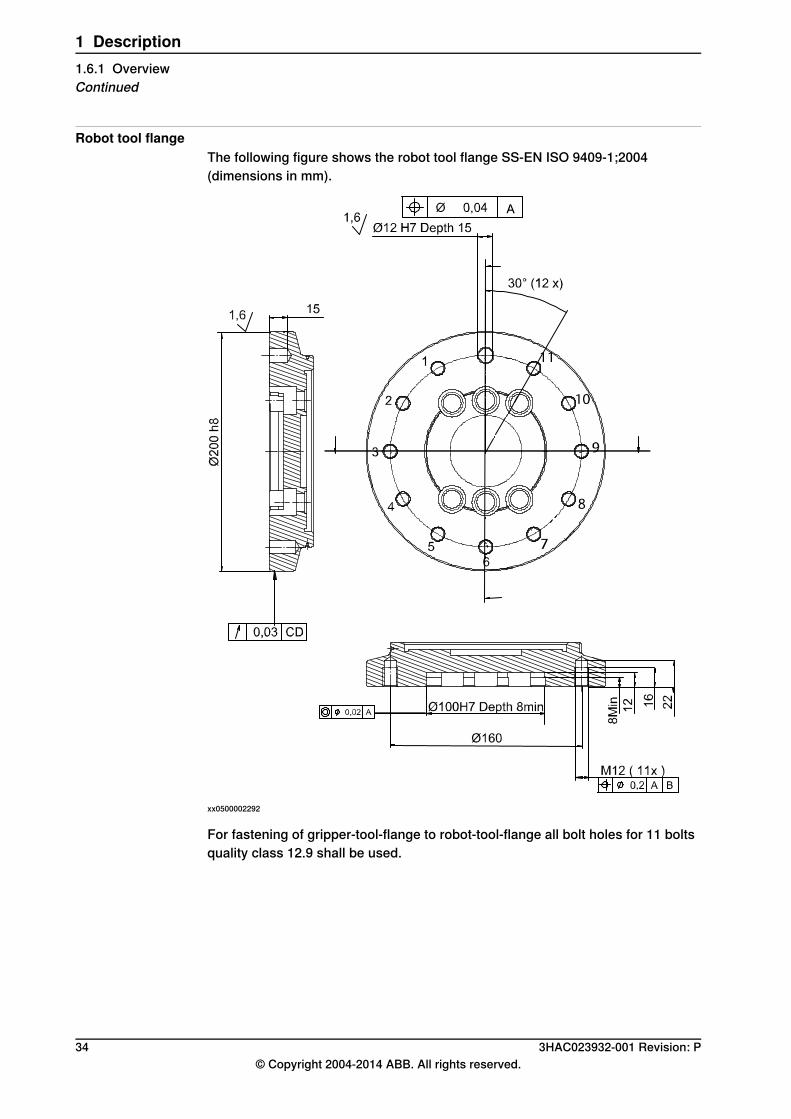
Robot tool flangeThe following figure shows the robot tool flange SS-EN ISO 9409-1;2004(dimensions in mm).
xx0500002292
For fastening of gripper-tool-flange to robot-tool-flange all bolt holes for 11 boltsquality class 12.9 shall be used.
34 3HAC023932-001 Revision: P© Copyright 2004-2014 ABB. All rights reserved.
1 Description1.6.1 OverviewContinued
1.7 Robot motion
1.7.1 Introduction
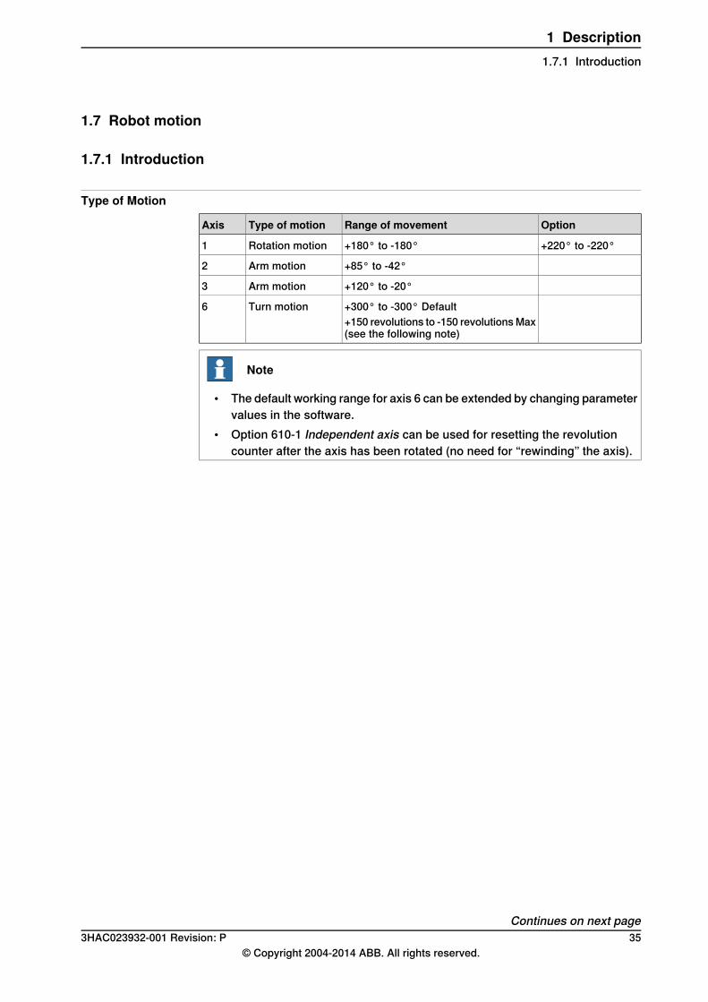
Type of Motion
OptionRange of movementType of motionAxis
+220° to -220°+180° to -180°Rotation motion1
+85° to -42°Arm motion2
+120° to -20°Arm motion3
+300° to -300° DefaultTurn motion6+150 revolutions to -150 revolutionsMax(see the following note)
Note
• The default working range for axis 6 can be extended by changing parametervalues in the software.
• Option 610-1 Independent axis can be used for resetting the revolutioncounter after the axis has been rotated (no need for “rewinding” the axis).
Continues on next page3HAC023932-001 Revision: P 35
© Copyright 2004-2014 ABB. All rights reserved.
1 Description1.7.1 Introduction
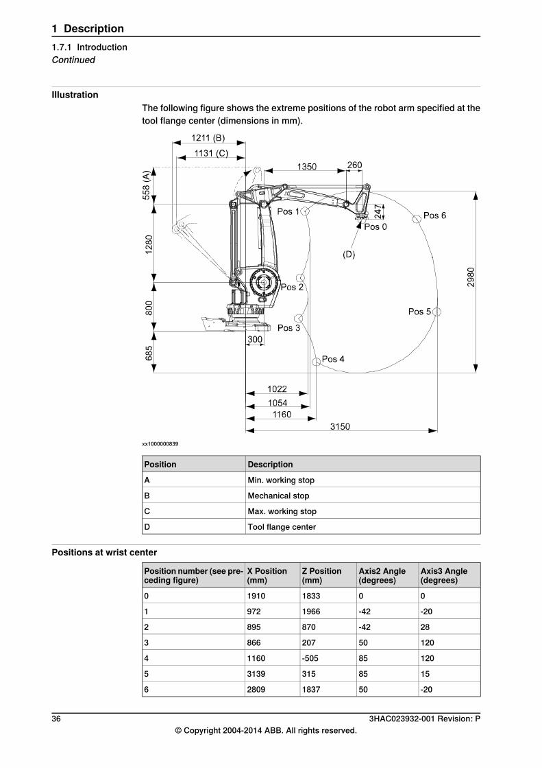
IllustrationThe following figure shows the extreme positions of the robot arm specified at thetool flange center (dimensions in mm).
xx1000000839
DescriptionPosition
Min. working stopA
Mechanical stopB
Max. working stopC
Tool flange centerD
Positions at wrist center
Axis3 Angle(degrees)
Axis2 Angle(degrees)
Z Position(mm)
X Position(mm)
Position number (see pre-ceding figure)
00183319100
-20-4219669721
28-428708952
120502078663
12085-50511604
158531531395
-2050183728096
36 3HAC023932-001 Revision: P© Copyright 2004-2014 ABB. All rights reserved.
1 Description1.7.1 IntroductionContinued
1.7.2 Performance according to ISO 9283
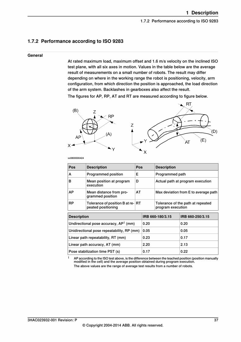
GeneralAt rated maximum load, maximum offset and 1.6 m/s velocity on the inclined ISOtest plane, with all six axes in motion. Values in the table below are the averageresult of measurements on a small number of robots. The result may differdepending on where in the working range the robot is positioning, velocity, armconfiguration, from which direction the position is approached, the load directionof the arm system. Backlashes in gearboxes also affect the result.The figures for AP, RP, AT and RT are measured according to figure below.
xx0800000424
DescriptionPosDescriptionPos
Programmed pathEProgrammed positionA
Actual path at program executionDMean position at programexecution
B
Max deviation from E to average pathATMean distance from pro-grammed position
AP
Tolerance of the path at repeatedprogram execution
RTTolerance of position B at re-peated positioning
RP
IRB 660-250/3.15IRB 660-180/3.15Description
0.200.20Undirectional pose accuracy, AP i (mm)
0.050.05Unidirectional pose repeatability, RP (mm)
0.170.23Linear path repeatability, RT (mm)
2.132.20Linear path accuracy, AT (mm)
0.220.17Pose stabilization time PST (s)i AP according to the ISO test above, is the difference between the teached position (positionmanually
modified in the cell) and the average position obtained during program execution.The above values are the range of average test results from a number of robots.
3HAC023932-001 Revision: P 37© Copyright 2004-2014 ABB. All rights reserved.
1 Description1.7.2 Performance according to ISO 9283
1.7.3 Velocity
Maximum axis speeds
IRB 660-250/3.15IRB 660-180/3.15Axis No.
95°/s130°/s1
95°/s130°/s2
95°/s130°/s3
240°/s300°/s6
There is a supervision function to prevent overheating in applications with intensiveand frequent movements.
Axis ResolutionApprox. 0.01º on each axis.
38 3HAC023932-001 Revision: P© Copyright 2004-2014 ABB. All rights reserved.
1 Description1.7.3 Velocity
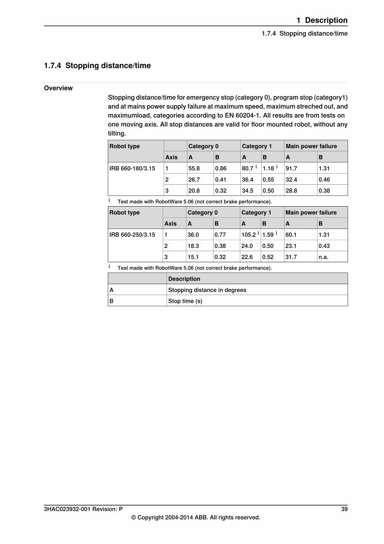
1.7.4 Stopping distance/time
OverviewStopping distance/time for emergency stop (category 0), program stop (category1)and at mains power supply failure at maximum speed, maximum streched out, andmaximumload, categories according to EN 60204-1. All results are from tests onone moving axis. All stop distances are valid for floor mounted robot, without anytilting.
Main power failureCategory 1Category 0Robot type
BABABAAxis
1.3191.71.18 i80.7 i0.8655.81IRB 660-180/3.15
0.4632.40.5536.40.4126.72
0.3828.80.5034.50.3220.83i Test made with RobotWare 5.06 (not correct brake performance).
Main power failureCategory 1Category 0Robot type
BABABAAxis
1.3160.11.59 i105.2 i0.7736.01IRB 660-250/3.15
0.4323.10.5024.00.3818.32
n.a.31.70.5222.60.3215.13i Test made with RobotWare 5.06 (not correct brake performance).
Description
Stopping distance in degreesA
Stop time (s)B
3HAC023932-001 Revision: P 39© Copyright 2004-2014 ABB. All rights reserved.
1 Description1.7.4 Stopping distance/time
1.8 Customer connections
1.8.1 Introduction
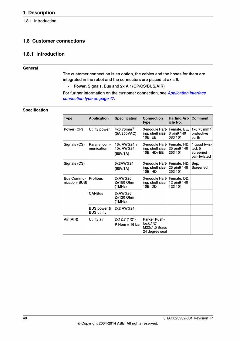
GeneralThe customer connection is an option, the cables and the hoses for them areintegrated in the robot and the connectors are placed at axis 6.
• Power, Signals, Bus and 2x Air (CP/CS/BUS/AIR)For further information on the customer connection, see Application interfaceconnection type on page 47.
Specification
CommentHarting Art-icle No.
Connectiontype
SpecificationApplicationType
1x0.75mm2protectiveearth
Female, EE,8 pin9 140083 101
3-module Hart-ing, shell size10B, EE
4x0.75mm2(5A/250VAC)
Utility powerPower (CP)
4 quad twis-ted, 5screenedpair twisted
Female, HD,25 pin9 140253 101
3-module Hart-ing, shell size10B, HD+EE
16x AWG24 +10x AWG24(50V/1A)
Parallel com-munication
Signals (CS)
Sep.Screened
Female, HD,25 pin9 140253 101
3-module Hart-ing, shell size10B, HD
5x2AWG24(50V/1A)
Signals (CS)
Female, DD,12 pin9 140123 101
3-module Hart-ing, shell size10B, DD
2xAWG26,Z=150 Ohm(1MHz)
ProfibusBus Commu-nication (BUS)
2xAWG26,Z=120 Ohm(1MHz)
CANBus
2x2 AWG24BUS power &BUS utility
Parker Push-lock,1/2”M22x1,5 Brass24 degree seal
2x12.7 (1/2”)P Nom = 16 bar
Utility airAir (AIR)
40 3HAC023932-001 Revision: P© Copyright 2004-2014 ABB. All rights reserved.
1 Description1.8.1 Introduction
1.9 Maintenance and troubleshooting
1.9.1 Introduction
GeneralThe robot requires only minimum maintenance during operation. It has beendesigned to make it as easy to service as possible:
• Maintenance-free AC motors are used• Oil is used for the gear boxes• The cabling is routed for longevity, and in the unlikely event of a failure, its
modular design makes it easy to change
MaintenanceThemaintenance intervals depend on the use of the robot, the requiredmaintenanceactivities also depends on selected options. For detailed information onmaintenanceprocedures, see Product manual - IRB 660, chapter Maintenance.
3HAC023932-001 Revision: P 41© Copyright 2004-2014 ABB. All rights reserved.
1 Description1.9.1 Introduction

This page is intentionally left blank

2 Specification of variants and options2.1 Introduction to variants and options
GeneralThe different variants and options for the IRB 660 are described in the followingsections. The same option numbers are used here as in the specification form.
Related informationFor the controller see Product specification - Controller IRC5 with FlexPendant.For the software options see Product specification - Controller software IRC5.
3HAC023932-001 Revision: P 43© Copyright 2004-2014 ABB. All rights reserved.
2 Specification of variants and options2.1 Introduction to variants and options
2.2 Manipulator
Variants
Reach (m)Handling capacity (kg)IRB TypeOption
3.15180660435-58
3.15250660435-59
Manipulator color
NoteDescriptionOption
ABB Orange standard209-1
ABB White standard209-3
Standard colorABBGraphiteWhite standard209-202
The robot is painted inchosen RAL - color
209-3 --192
Note
Notice that delivery time for painted spare parts will increase for none standardcolors.
Equipment
DescriptionTypeOption
A safety lamp with an orange fixed light can be mounted onthe manipulator. The lamp is active in MOTORS ON mode.The safety lamp is required on a UL/UR approved robot.
Safety lamp213-1
Lifting device on the manipulator for fork-lift handling.Fork lift device159-1
Can also be used for IRB 7600. See dimension drawing inMounting the manipulator on page 21.
Base plate37-1
Resolver connection, axis 7
NoteDescriptionOption
Needed for Connection box (BRB), option 1018-1 to -3, onspecification form for Motor Units. Used together with firstadditional drive, option 907-1.
On base864-1
Electronic Position Switches (EPS)The mechanical position switches indicating the position of the three main axesare replaced with electronic position switches for up to 7 axes, for increasedflexibility and robustness. For more detailed information, see Productspecification - Controller IRC5with FlexPendant andApplicationmanual - ElectronicPosition Switches.
Continues on next page44 3HAC023932-001 Revision: P
© Copyright 2004-2014 ABB. All rights reserved.
2 Specification of variants and options2.2 Manipulator
Work range limit Axis 1To increase the safety of the robot, the working range of axis 1 can be restrictedby extra mechanical stops.
DescriptionTypeOption
Two stopswhich allow theworking range to be restrictedin increments of 7.5°.
Axis 1, 7.5 degrees29-2
Extended work range
DescriptionTypeOption
To extend the working range on Axis1 from ±180°to ±220°.
Extended work range axis 1561-1
When the option is used the mechanical stop shallbe disassembled.Electronic Position Switches, option 810-1, is re-quired.
Warranty
DescriptionTypeOption
Standard warranty is 12months fromCustomer DeliveryDate or latest 18 months after Factory Shipment Date,whichever occurs first. Warranty terms and conditionsapply.
Standard warranty438-1
Standard warranty extended with 12 months from enddate of the standard warranty. Warranty terms and con-ditions apply. Contact Customer Service in case of otherrequirements.
Standard warranty + 12months
438-2
Standard sarranty extended with 18 months from enddate of the standard warranty. Warranty terms and con-ditions apply. Contact Customer Service in case of otherrequirements.
Standard warranty + 18months
438-4
Standard warranty extended with 24 months from enddate of the standard warranty. Warranty terms and con-ditions apply. Contact Customer Service in case of otherrequirements.
Standard warranty + 24months
438-5
Standard warranty extended with 6 months from enddate of the standard warranty. Warranty terms and con-ditions apply.
Standard warranty + 6months
438-6
Standard warranty extended with 30 months from enddate of the standard warranty. Warranty terms and con-ditions apply.
Standard warranty + 30months
438-7
Maximum 6 months postponed start of standard war-ranty, starting from factory shipment date. Note that noclaims will be accepted for warranties that occurred be-fore the end of stock warranty. Standard warranty com-mences automatically after 6 months from FactoryShipment Date or from activation date of standard war-ranty in WebConfig.
Note
Special conditions are applicable, seeRoboticsWarrantyDirectives.
Stock warranty438-8
3HAC023932-001 Revision: P 45© Copyright 2004-2014 ABB. All rights reserved.
2 Specification of variants and options2.2 Manipulator
Continued
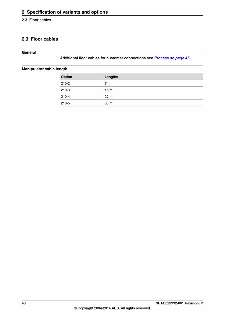
2.3 Floor cables
GeneralAdditional floor cables for customer connections see Process on page 47.
Manipulator cable length
LengthsOption
7 m210-2
15 m210-3
22 m210-4
30 m210-5
46 3HAC023932-001 Revision: P© Copyright 2004-2014 ABB. All rights reserved.
2 Specification of variants and options2.3 Floor cables
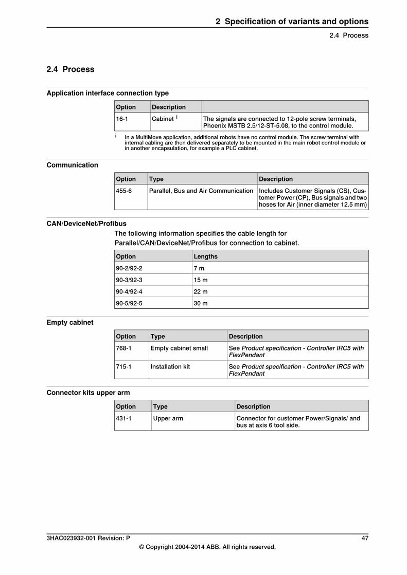
2.4 Process
Application interface connection type
DescriptionOption
The signals are connected to 12-pole screw terminals,Phoenix MSTB 2.5/12-ST-5.08, to the control module.
Cabinet i16-1
i In a MultiMove application, additional robots have no control module. The screw terminal withinternal cabling are then delivered separately to be mounted in the main robot control module orin another encapsulation, for example a PLC cabinet.
Communication
DescriptionTypeOption
Includes Customer Signals (CS), Cus-tomer Power (CP), Bus signals and twohoses for Air (inner diameter 12.5 mm)
Parallel, Bus and Air Communication455-6
CAN/DeviceNet/ProfibusThe following information specifies the cable length forParallel/CAN/DeviceNet/Profibus for connection to cabinet.
LengthsOption
7 m90-2/92-2
15 m90-3/92-3
22 m90-4/92-4
30 m90-5/92-5
Empty cabinet
DescriptionTypeOption
See Product specification - Controller IRC5 withFlexPendant
Empty cabinet small768-1
See Product specification - Controller IRC5 withFlexPendant
Installation kit715-1
Connector kits upper arm
DescriptionTypeOption
Connector for customer Power/Signals/ andbus at axis 6 tool side.
Upper arm431-1
3HAC023932-001 Revision: P 47© Copyright 2004-2014 ABB. All rights reserved.
2 Specification of variants and options2.4 Process
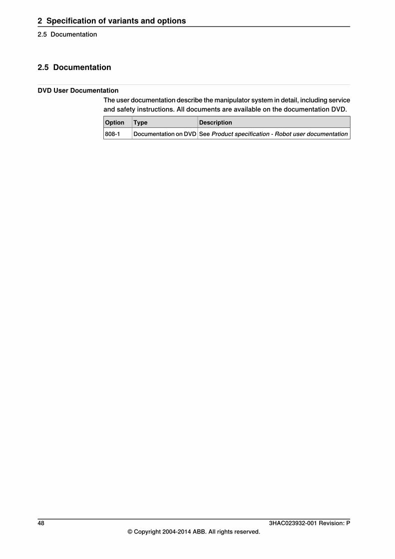
2.5 Documentation
DVD User DocumentationThe user documentation describe themanipulator system in detail, including serviceand safety instructions. All documents are available on the documentation DVD.
DescriptionTypeOption
See Product specification - Robot user documentationDocumentation onDVD808-1
48 3HAC023932-001 Revision: P© Copyright 2004-2014 ABB. All rights reserved.
2 Specification of variants and options2.5 Documentation
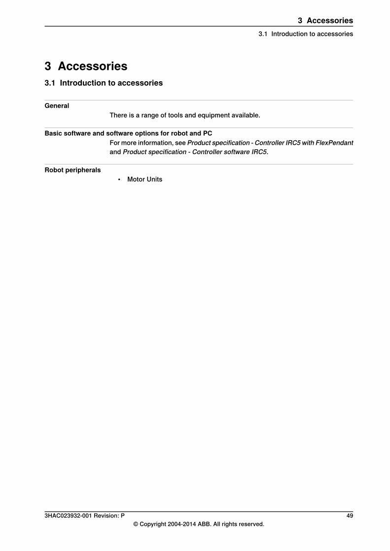
3 Accessories3.1 Introduction to accessories
GeneralThere is a range of tools and equipment available.
Basic software and software options for robot and PCFor more information, see Product specification - Controller IRC5 with FlexPendantand Product specification - Controller software IRC5.
Robot peripherals• Motor Units
3HAC023932-001 Revision: P 49© Copyright 2004-2014 ABB. All rights reserved.
3 Accessories3.1 Introduction to accessories

This page is intentionally left blank
IndexAaccessories, 49
Bbus cables, 47
Ccable lengths, 46Calibration Pendulum, 26CAN, 47communication signals, 47connections
application interface, 47customer connections, 40
DDeviceNet, 47documentation, 48
EElectronic Position Switches, 44EPS, 44extra load, 31
Ffine calibration, 26
Iinstructions, 48ISO 9283, 37
Lload diagrams, 28
Mmaintenance, 41manuals, 48maximum load, 30moment of intertia, 30
Ooptions, 43
PProfibus, 47protection standards, 17
Ssafety standards, 17service instructions, 48standards
ANSI, 18CAN, 18EN, 17EN IEC, 17EN ISO, 17protection, 17safety, 17
standard warranty, 45stock warranty, 45
Uuser documentation, 48
Vvariants, 43–44
Wwarranty, 45
3HAC023932-001 Revision: P 51© Copyright 2004-2014 ABB. All rights reserved.
Index


Contact us
ABB ABDiscrete Automation and MotionRoboticsS-721 68 VÄSTERÅS, SwedenTelephone +46 (0) 21 344 400
ABB AS, RoboticsDiscrete Automation and MotionNordlysvegen 7, N-4340 BRYNE, NorwayBox 265, N-4349 BRYNE, NorwayTelephone: +47 51489000
ABB Engineering (Shanghai) Ltd.5 Lane 369, ChuangYe RoadKangQiao Town, PuDong DistrictSHANGHAI 201319, ChinaTelephone: +86 21 6105 6666
www.abb.com/robotics
3HAC
0239
32-001
,Rev
P,en