product specification - ateron robotics products ab assumes no responsibility for any errors that...
TRANSCRIPT
Product Specification
3HAC 3991-1
IRB 1400
M98 / BW OS 3.2 / Rev. 1

The information in this document is subject to change without notice and should not be construed as a commitment by ABB Robotics Products AB. ABB Robotics Products AB assumes no responsibility for any errors that may appear in this document.
In no event shall ABB Robotics Products AB be liable for incidental or consequential damages arising from use of this document or of the software and hardware described in this document.
This document and parts thereof must not be reproduced or copied without ABB Robotics Products AB´s written permission, and contents thereof must not be imparted to a third party nor be used for any unauthorized purpose. Contravention will be prosecuted.
Additional copies of this document may be obtained from ABB Robotics Products AB at its then current charge.
© ABB Robotics Products AB
Article number: 3HAC 7677-1Issue: M2000/Rev.1
ABB Robotics Products ABS-721 68 Västerås
Sweden
Product Specification IRB 1400
CONTENTSPage
1 Introduction ..................................................................................................................... 3
2 Description ....................................................................................................................... 5
2.1 Structure.................................................................................................................. 5
2.2 Safety/Standards ..................................................................................................... 6
2.3 Operation ................................................................................................................ 7
2.4 Installation .............................................................................................................. 9
2.5 Programming .......................................................................................................... 9
2.6 Automatic Operation .............................................................................................. 12
2.7 Maintenance and Troubleshooting ......................................................................... 12
2.8 Robot Motion.......................................................................................................... 14
2.9 External Axes ......................................................................................................... 17
2.10 Inputs and Outputs................................................................................................ 17
2.11 Serial Communication .......................................................................................... 18
3 Technical specification .................................................................................................... 19
3.1 Structure.................................................................................................................. 19
3.2 Safety/Standards ..................................................................................................... 22
3.3 Operation ................................................................................................................ 23
3.4 Installation .............................................................................................................. 24
3.5 Programming .......................................................................................................... 28
3.6 Automatic Operation .............................................................................................. 32
3.7 Maintenance and Troubleshooting ......................................................................... 32
3.8 Robot Motion.......................................................................................................... 33
3.9 External Axes ......................................................................................................... 36
3.10 Inputs and Outputs................................................................................................ 37
3.11 Communication..................................................................................................... 41
4 Specification of Variants and Options........................................................................... 43
5 Accessories ....................................................................................................................... 57
6 Index................................................................................................................................. 59
Product Specification IRB 1400 M98/BaseWare OS 3.2 1

Product Specification IRB 1400
2 Product Specification IRB 1400 M98/BaseWare OS 3.2
Introduction
t
, in can
1 Introduction
Thank you for your interest in the IRB 1400. This manual will give you an overview of the characteristics and performance of the robot.
IRB 1400 is a 6-axis industrial robot, designed specifically for manufacturing industries that use flexible robot-based automation. The robot has an open structure that is specially adapted for flexible use, and can communicate extensively with external systems.
The robot is equipped with an operating system called BaseWare OS. BaseWare OS controls every aspect of the robot, like motion control, development and execution of application programs communication etc.
The functions in this document are all included in BaseWare OS, if not otherwise specified. For additional functionality, the robot can be equipped with optional software for application support - for example gluing and arc welding, communication features - network communication - and advanced functions such as multitasking, sensor control etc. For a complete description on optional software, see the Product Specification RobotWare.
All the features are not described in this document. For a more complete and detailed description, please see the User’s Guide, RAPID Reference Manual and ProducManual, or contact your nearest ABB Flexible Automation Centre.
Different robot versions
The IRB 1400, as mentioned above, is available in two different versions:
- IRB 1400, for floor mounting
- IRB 1400H, for inverted mounting.
How to use this manual
The characteristics of the robot are described in Chapter 2: Description.
The most important technical data is listed in Chapter 3: Technical specification.
Note that the sections in chapter 2 and 3 are related to each other. For examplesection 2.2 you can find an overview of safety and standards, in section 3.2 youfind more detailed information.
To make sure that you have ordered a robot with the correct functionality, see Chapter 4: Specification of Variants and Options.
In Chapter 5 you will find accessories for the robot.
Chapter 6 contains an Index, to make things easier to find.
Product Specification IRB 1400 M98/BaseWare OS 3.2 3
Introduction
Other manuals
The User’s Guide is a reference manual with step by step instructions on how toperform various tasks.
The programming language is described in the RAPID Reference Manual.
The Product Manual describes how to install the robot, as well as maintenance procedures and troubleshooting.
The Product Specification RobotWare describes the software options.
4 Product Specification IRB 1400 M98/BaseWare OS 3.2
Description
2 Description
2.1 Structure
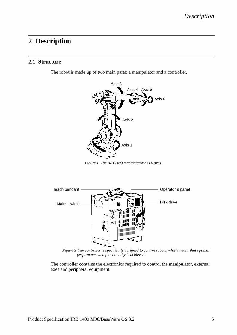
The robot is made up of two main parts: a manipulator and a controller.
Figure 1 The IRB 1400 manipulator has 6 axes.
Figure 2 The controller is specifically designed to control robots, which means that optimal performance and functionality is achieved.
The controller contains the electronics required to control the manipulator, external axes and peripheral equipment.
Axis 6
Axis 1
Axis 2
Axis 3
Axis 4 Axis 5
Teach pendant Operator´s panel
Disk driveMains switch
Product Specification IRB 1400 M98/BaseWare OS 3.2 5
Description
C’s
tem nt
n.). of obot.
teach
ety
safety func-
al cond
2.2 Safety/Standards
The robot complies fully with the health and safety standards specified in the EEMachinery Directives as well as ANSI/RIA 15.06-1992.
The robot is designed with absolute safety in mind. It has a dedicated safety sysbased on a two-channel circuit which is monitored continuously. If any componefails, the electrical power supplied to the motors shuts off and the brakes engage.
Safety category 3Malfunction of a single component, such as a sticking relay, will be detected at the next MOTOR OFF/MOTOR ON operation. MOTOR ON is then prevented and the faulty section is indicated. This complies with category 3 of EN 954-1, Safety of machinery - safety related parts of control systems - Part 1.
Selecting the operating mode The robot can be operated either manually or automatically. In manual mode, the robot can only be operated via the teach pendant, i.e. not by any external equipment.
Reduced speedIn manual mode, the speed is limited to a maximum of 250 mm/s (600 inches/miA speed limitation applies not only to the TCP (Tool Centre Point), but to all partsthe robot. It is also possible to monitor the speed of equipment mounted on the r
Three position enabling deviceThe enabling device on the teach pendant must be used to move the robot when in man-ual mode. The enabling device consists of a switch with three positions, meaning that all robot movements stop when either the enabling device is pushed fully in, or when it is released completely. This makes the robot safer to operate.
Safe manual movementThe robot is moved using a joystick instead of the operator having to look at the pendant to find the right key.
Over-speed protectionThe speed of the robot is monitored by two independent computers.
Emergency stopThere is one emergency stop push button on the controller and another on the teach pendant. Additional emergency stop buttons can be connected to the robot’s safchain circuit.
Safeguarded space stopThe robot has a number of electrical inputs which can be used to connect externalequipment, such as safety gates and light curtains. This allows the robot’s safetytions to be activated both by peripheral equipment and by the robot itself.
Delayed safeguarded space stopA delayed stop gives a smooth stop. The robot stops in the same way as at normprogram stop with no deviation from the programmed path. After approx. one sethe power supplied to the motors shuts off.
6 Product Specification IRB 1400 M98/BaseWare OS 3.2
Description
obot. ram
ry)
ipula-
dant
and earn t,
he r
Restricting the working spaceThe movement of each of the axes can be restricted using software limits. Axes 1 and 2 can also be restricted by means of an adjustable mechanical stop. Axis 3 can be restricted using an electrical limit switch.
Hold-to-run control“Hold-to-run” means that you must depress the start button in order to move the rWhen the key is released the robot will stop. The hold-to-run function makes progtesting safer.
Fire safetyBoth the manipulator and control system comply with UL’s (Underwriters Laboratotough requirements for fire safety.
Safety lampAs an option, the robot can be equipped with a safety lamp mounted on the mantor. This is activated when the motors are in the MOTORS ON state.
2.3 Operation
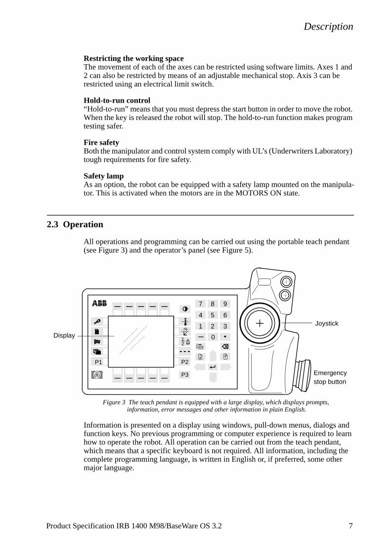
All operations and programming can be carried out using the portable teach pen(see Figure 3) and the operator’s panel (see Figure 5).
Figure 3 The teach pendant is equipped with a large display, which displays prompts, information, error messages and other information in plain English.
Information is presented on a display using windows, pull-down menus, dialogs function keys. No previous programming or computer experience is required to lhow to operate the robot. All operation can be carried out from the teach pendanwhich means that a specific keyboard is not required. All information, including tcomplete programming language, is written in English or, if preferred, some othemajor language.
21
2 3
0
1
4 5 6
7 8 9
P3
P1 P2
Joystick
Display
Emergencystop button
Product Specification IRB 1400 M98/BaseWare OS 3.2 7
Description
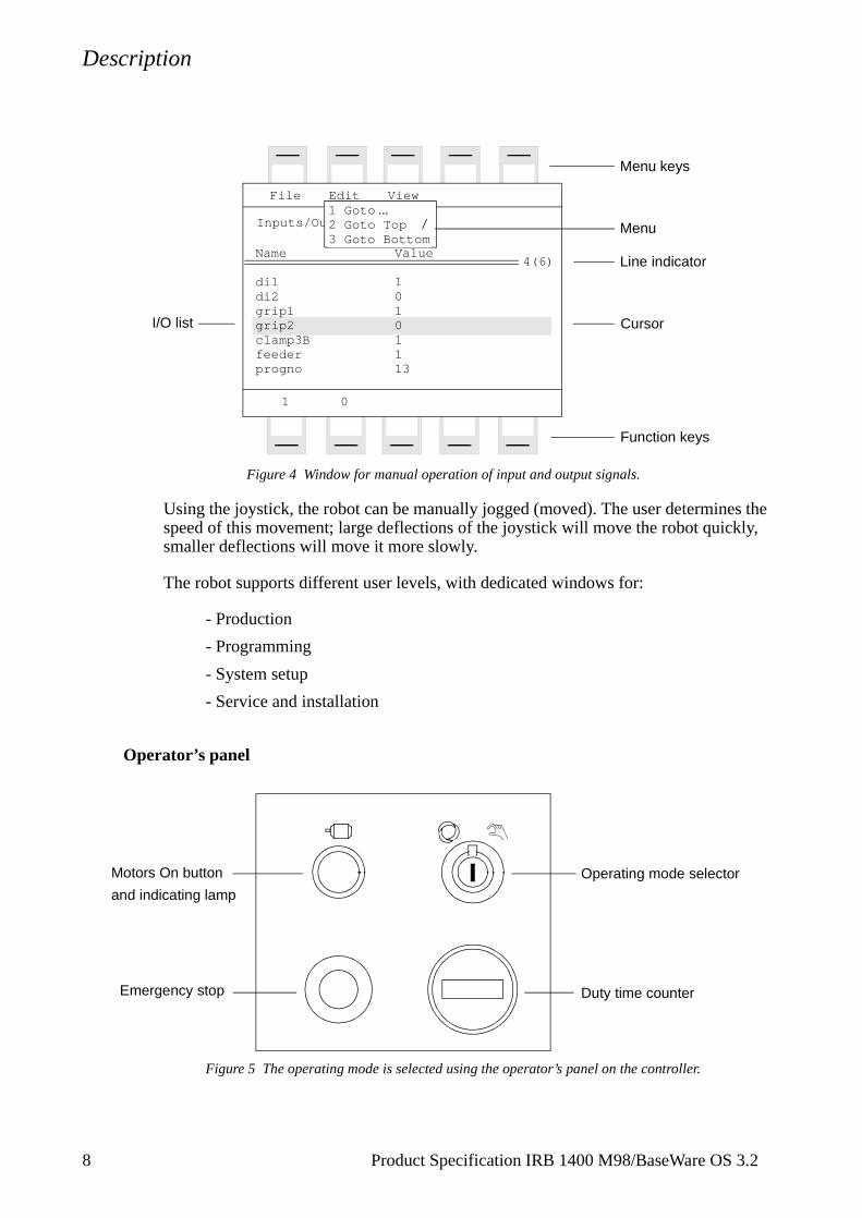
Figure 4 Window for manual operation of input and output signals.
Using the joystick, the robot can be manually jogged (moved). The user determines the speed of this movement; large deflections of the joystick will move the robot quickly, smaller deflections will move it more slowly.
The robot supports different user levels, with dedicated windows for:
- Production
- Programming
- System setup
- Service and installation
Operator’s panel
Figure 5 The operating mode is selected using the operator’s panel on the controller.
Inputs/Outputs
File
Value
10101113
Edit View
1 0
4(6)Name
di1di2grip1grip2clamp3Bfeederprogno
1 Goto ...2 Goto Top3 Goto Bottom
Menu keys
I/O list
Menu
Line indicator
Cursor
Function keys
Operating mode selector
Duty time counter
Motors On button
Emergency stop
and indicating lamp
8 Product Specification IRB 1400 M98/BaseWare OS 3.2
Description
utside
s
nged
be
of ns, mber
nt.
tc.
ithout
Using a key switch, the gantry robot can be locked in two or three different operating modes depending on chosen mode selector:
• Automatic mode: Running production
• Manual mode at reduced speed: Programming and setupMax. speed: 250 mm/s (600 inches/min.)
• Manual mode at full speed (option): Testing at full program speedEquipped with this mode, the robot is not approved according to ANSI/UL
Both the operator’s panel and the teach pendant can be mounted externally, i.e. othe cabinet. The robot can then be controlled from there.
The robot can be remotely controlled from a computer, PLC or from a customer’panel, using serial communication or digital system signals.
For more information on how to operate the robot, see the User’s Guide.
2.4 Installation
The robot has a standard configuration and can be operated immediately after installation. Its configuration is displayed in plain language and can easily be chausing the teach pendant. The configuration can be stored on a diskette and/or transferred to other robots that have the same characteristics.
There are two versions of IRB 1400, one for floor mounting and one for invertedmounting. An end effector, weighing a maximum of 5 kg, including payload, can mounted on the robot’s mounting flange (axis 6). Other equipment, weighing a maximum of 10 kg, can be mounted on the rear of the upper arm.
2.5 Programming
Programming the robot involves choosing instructions and arguments from lists appropriate alternatives. Users do not need to remember the format of instructiosince they are prompted in plain English. “See and pick” is used instead of “remeand type”.
The programming environment can be easily customised using the teach penda
- Shop floor language can be used to name programs, signals, counters, e
- New instructions can be easily written.
- The most common instructions can be collected in easy-to-use pick lists.
- Positions, registers, tool data, or other data, can be created.
Programs, parts of programs and any modifications can be tested immediately whaving to translate the program.
100%
Product Specification IRB 1400 M98/BaseWare OS 3.2 9
Description
gives cally of
PC
The program is stored as a normal PC text file, which means that it can be edited using a standard PC.
Movements
A sequence of movements is programmed as a number of partial movements between the positions to which you want the robot to move.
The end position of a movement is selected either by manually jogging the robot to the desired position with the joystick, or by referring to a previously defined position.
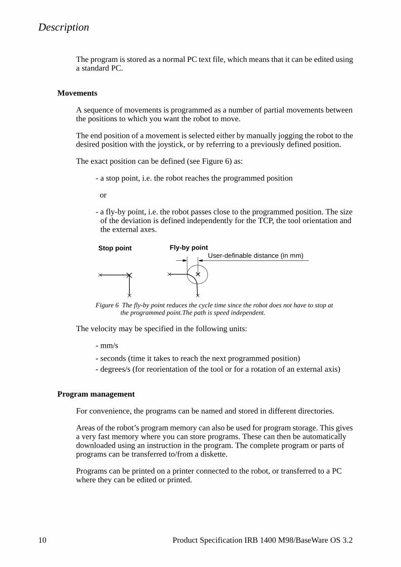
The exact position can be defined (see Figure 6) as:
- a stop point, i.e. the robot reaches the programmed position
or
- a fly-by point, i.e. the robot passes close to the programmed position. The size of the deviation is defined independently for the TCP, the tool orientation and the external axes.
Figure 6 The fly-by point reduces the cycle time since the robot does not have to stop atthe programmed point.The path is speed independent.
The velocity may be specified in the following units:
- mm/s
- seconds (time it takes to reach the next programmed position)- degrees/s (for reorientation of the tool or for a rotation of an external axis)
Program management
For convenience, the programs can be named and stored in different directories.
Areas of the robot’s program memory can also be used for program storage. Thisa very fast memory where you can store programs. These can then be automatidownloaded using an instruction in the program. The complete program or partsprograms can be transferred to/from a diskette.
Programs can be printed on a printer connected to the robot, or transferred to a where they can be edited or printed.
Stop point Fly-by pointUser-definable distance (in mm)
10 Product Specification IRB 1400 M98/BaseWare OS 3.2
Description
copy, o be
since
e used.
Editing programs
Programs can be edited using standard editing commands, i.e. “cut-and-paste”,delete, find and change, undo etc. Individual arguments in an instruction can alsedited using these commands.
No reprogramming is necessary when processing left-hand and right-hand parts,the program can be mirrored in any plane.
A robot position can easily be changed either by:
- jogging the robot with the joystick to a new position and then pressing the“ModPos” key (this registers the new position)
or by
- entering or modifying numeric values.
To prevent unauthorised personnel making program changes, passwords can b
Testing programs
Several helpful functions can be used when testing programs. For example, it ispossible to:
- start from any instruction
- execute an incomplete program
- run one cycle
- execute forward/backward step-by-step
- simulate wait conditions
- temporarily reduce the speed
- change a position
- tune (displace) a position during program execution.
For more information, see the User´s Guide and RAPID Reference Manual.
Product Specification IRB 1400 M98/BaseWare OS 3.2 11
Description
2.6 Automatic Operation
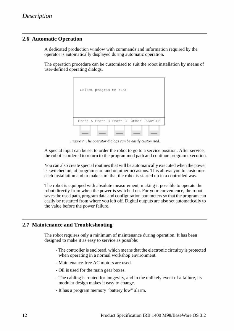
A dedicated production window with commands and information required by the operator is automatically displayed during automatic operation.
The operation procedure can be customised to suit the robot installation by means of user-defined operating dialogs.
Figure 7 The operator dialogs can be easily customised.
A special input can be set to order the robot to go to a service position. After service, the robot is ordered to return to the programmed path and continue program execution.
You can also create special routines that will be automatically executed when the power is switched on, at program start and on other occasions. This allows you to customise each installation and to make sure that the robot is started up in a controlled way.
The robot is equipped with absolute measurement, making it possible to operate the robot directly from when the power is switched on. For your convenience, the robot saves the used path, program data and configuration parameters so that the program can easily be restarted from where you left off. Digital outputs are also set automatically to the value before the power failure.
2.7 Maintenance and Troubleshooting
The robot requires only a minimum of maintenance during operation. It has been designed to make it as easy to service as possible:
- The controller is enclosed, which means that the electronic circuitry is protected when operating in a normal workshop environment.
- Maintenance-free AC motors are used.
- Oil is used for the main gear boxes.
- The cabling is routed for longevity, and in the unlikely event of a failure, its modular design makes it easy to change.
- It has a program memory “battery low” alarm.
Front A Front B Front C Other SERVICE
Select program to run:
12 Product Specification IRB 1400 M98/BaseWare OS 3.2
Description
The robot has several functions to provide efficient diagnostics and error reports:
- It performs a self test when power on is set.
- Errors are indicated by a message displayed in plain language. The message includes the reason for the fault and suggests recovery action.
- A board error is indicated by an LED on the faulty unit.
- Faults and major events are logged and time-stamped. This makes it possible to detect error chains and provides the background for any downtime. The log can be read on the display of the teach pendant, stored in a file and also printed on a printer.
- There are commands and service programs in RAPID to test units and func-tions.
Most errors detected by the user program can also be reported to and handled by the standard error system. Error messages and recovery procedures are displayed in plain language.
Product Specification IRB 1400 M98/BaseWare OS 3.2 13
Description
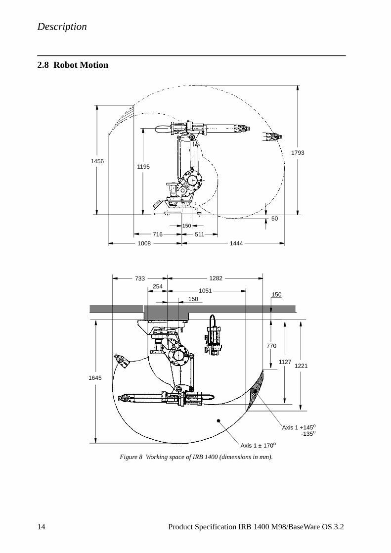
2.8 Robot Motion
Figure 8 Working space of IRB 1400 (dimensions in mm).
1195
1008 1444
150
511
1793
50
716
1456
1051150
2541282733
1645
770
11271221
150
Axis 1 ± 170o
Axis 1 +145o
-135o
14 Product Specification IRB 1400 M98/BaseWare OS 3.2

Description
ss of op, a
e two
le to stem
t.
Motion performance
The QuickMoveTM concept means that a self-optimizing motion control is used. The robot automatically optimizes the servo parameters to achieve the best possible performance throughout the cycle - based on load properties, location in working area, velocity and direction of movement.
- No parameters have to be adjusted to achieve correct path, orientation and velocity.
- Maximum acceleration is always obtained (acceleration can be reduced, e.g. when handling fragile parts).
- The number of adjustments that have to be made to achieve the shortest possi-ble cycle time are minimized.
The TrueMoveTM concept means that the programmed path is followed – regardlethe speed or operating mode – even after an emergency stop, a safeguarded stprocess stop, a program stop or a power failure.
The robot can, in a controlled way, pass through singular points, i.e. points wheraxes coincide.
Coordinate systems
Figure 9 The coordinate systems, used to make jogging and off-line programming easier.
The world coordinate system defines a reference to the floor, which is the startingpoint for the other coordinate systems. Using this coordinate system, it is possibrelate the robot position to a fixed point in the workshop. The world coordinate syis also very useful when two robots work together or when using a robot carrier.
The base coordinate system is attached to the base mounting surface of the robo
The tool coordinate system specifies the tool’s centre point and orientation.
ObjectZ
Y
X
World coordinates
UserZ
Z
Y
Y
X
XX
Y
Base coordinates
Tool coordinates Y
Z
Tool Centre Point (TCP)XZ
coordinates coordinates
Product Specification IRB 1400 M98/BaseWare OS 3.2 15

Description
nd ld
be
sible peed
n - ection
ion djust
ate
an be ance
an be
The user coordinate system specifies the position of a fixture or workpiece manipulator.
The object coordinate system specifies how a workpiece is positioned in a fixture or workpiece manipulator.
The coordinate systems can be programmed by specifying numeric values or jogging the robot through a number of positions (the tool does not have to be removed).
Each position is specified in object coordinates with respect to the tool’s position aorientation. This means that even if a tool is changed because it is damaged, the oprogram can still be used, unchanged, by making a new definition of the tool. If a fixture or workpiece is moved, only the user or object coordinate system has toredefined.
Stationary TCP
When the robot is holding a work object and working on a stationary tool, it is posto define a TCP for that tool. When that tool is active, the programmed path and sare related to the work object.
Program execution
The robot can move in any of the following ways:
- Joint motion (all axes move individually and reach the programmed position at the same time)
- Linear motion (the TCP moves in a linear path)
- Circle motion (the TCP moves in a circular path)
Soft servo - allowing external forces to cause deviation from programmed positiocan be used as an alternative to mechanical compliance in grippers, where imperfin processed objects can occur.
If the location of a workpiece varies from time to time, the robot can find its positby means of a digital sensor. The robot program can then be modified in order to athe motion to the location of the part.
Jogging
The robot can be manually operated in any one of the following ways:
- Axis-by-axis, i.e. one axis at a time
- Linearly, i.e. the TCP moves in a linear path (relative to one of the coordinsystems mentioned above)
- Reoriented around the TCP
It is possible to select the step size for incremental jogging. Incremental jogging cused to position the robot with high precision, since the robot moves a short disteach time the joystick is moved.
During manual operation, the current position of the robot and the external axes cdisplayed on the teach pendant.
16 Product Specification IRB 1400 M98/BaseWare OS 3.2
Description
,
t
mple, nt drive
ither he
a
s to be
trap s. In lim-
2.9 External Axes
The robot can control up to six external axes. These axes are programmed and moved using the teach pendant in the same way as the robot’s axes.
The external axes can be grouped into mechanical units to facilitate, for examplethe handling of robot carriers, workpiece manipulators, etc.
The robot motion can be simultaneously coordinated with a one-axis linear robocarrier and a rotational external axis.
A mechanical unit can be activated or deactivated to make it safe when, for examanually changing a workpiece located on the unit. In order to reduce investmecosts, any axes that do not have to be active at the same time can use the sameunit.
Programs can be reused in other mechanical units of the same type.
2.10 Inputs and Outputs
A distributed I/O system is used, which makes it possible to mount the I/O units einside the cabinet or outside the cabinet with a cable connecting the I/O unit to tcabinet.
A number of different input and output units can be installed:
- Digital inputs and outputs
- Analog inputs and outputs
- Remote I/O for Allen-Bradley PLC
- InterBus-S Slave
- Profibus DP Slave
The inputs and outputs can be configured to suit your installation:
- Each signal and board can be given a name, e.g. gripper, feeder
- I/O mapping (i.e. a physical connection for each signal)
- Polarity (active high or low)
- Cross connections
- Up to 16 digital signals can be grouped together and used as if they weresingle signal when, for example, entering a bar code
Signals can be assigned to special system functions, such as program start, so aable to control the robot from an external panel or PLC.
The robot can work as a PLC by monitoring and controlling I/O signals:
- I/O instructions can be executed concurrent to the robot motion.
- Inputs can be connected to trap routines. (When such an input is set, theroutine starts executing. Following this, normal program execution resumemost cases, this will not have any visible effect on the robot motion, i.e. if aited number of instructions are executed in the trap routine.)
Product Specification IRB 1400 M98/BaseWare OS 3.2 17
Description
- Background programs (for monitoring signals, for example) can be run in parallel with the actual robot program. Requires option Multitasking, see Product Specification RobotWare.
Manual functions are available to:
- List all the signal values
- Create your own list of your most important signals
- Manually change the status of an output signal
- Print signal information on a printer
Signal connections consist of either connectors or screw terminals, which are located in the controller. I/O signals can also be routed to connectors on the upper arm of the robot.
2.11 Serial Communication
The robot can communicate with computers or other equipment via RS232/RS422 serial channels or via Ethernet. However this requires optional software, see the Product Specification RobotWare.
18 Product Specification IRB 1400 M98/BaseWare OS 3.2
Technical specification
3 Technical specification
3.1 Structure
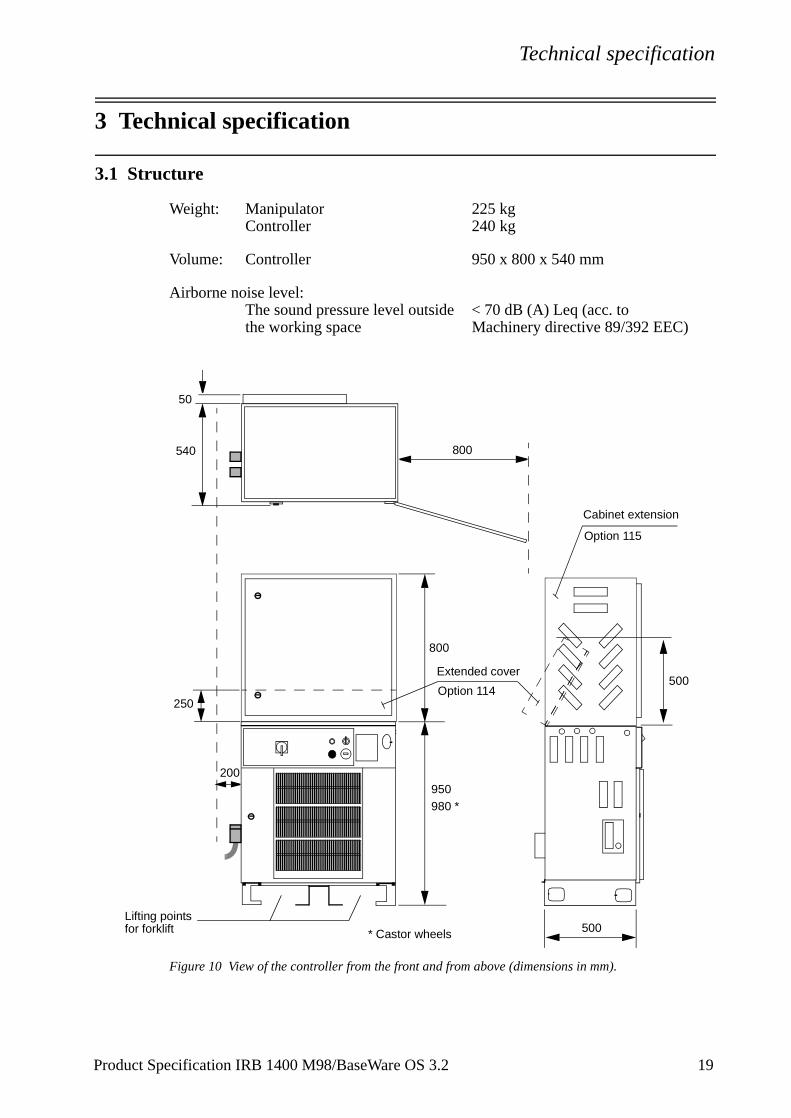
Weight: Manipulator 225 kgController 240 kg
Volume: Controller 950 x 800 x 540 mm
Airborne noise level:The sound pressure level outside < 70 dB (A) Leq (acc. tothe working space Machinery directive 89/392 EEC)
Figure 10 View of the controller from the front and from above (dimensions in mm).
200
50
540
950980 *
500
500
800
Lifting pointsfor forklift * Castor wheels
800
250
Extended cover
Option 114
Cabinet extension
Option 115
Product Specification IRB 1400 M98/BaseWare OS 3.2 19
Technical specification
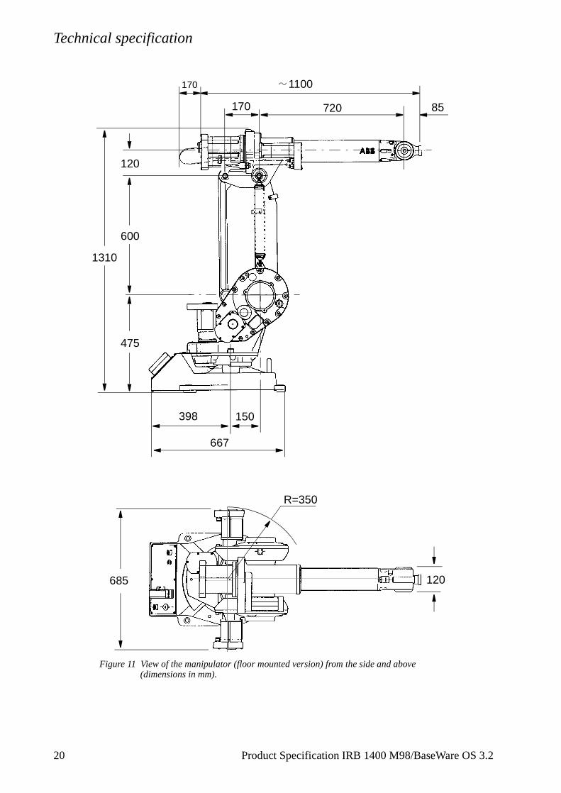
Figure 11 View of the manipulator (floor mounted version) from the side and above(dimensions in mm).
1100
1310
685
R=350
120
85720170
475
600
120
150398
667
170
20 Product Specification IRB 1400 M98/BaseWare OS 3.2
Technical specification
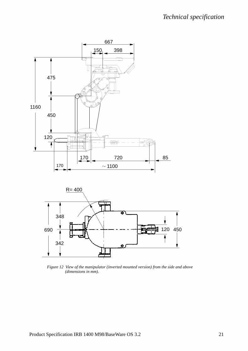
Figure 12 View of the manipulator (inverted mounted version) from the side and above(dimensions in mm).
1100
1160
690
R= 400
120
85720
475
450
120
398150
667
342
348
450
170
170
Product Specification IRB 1400 M98/BaseWare OS 3.2 21
Technical specification
y stop
3.2 Safety/Standards
The robot conforms to the following standards:
EN 292-1 Safety of machinery, terminology
EN 292-2 Safety of machinery, technical specifications
EN 954-1 Safety of machinery, safety related parts of control systems
EN 602041 Electrical equipment of industrial machines
IEC 204-1 Electrical equipment of industrial machines
ISO 10218, EN 775 Manipulating industrial robots, safety
ANSI/RIA 15.06/1992 Industrial robots, safety requirements
ISO 9787 Manipulating industrial robots, coordinate systems and motions
IEC 529 Degrees of protection provided by enclosures
EN 50081-2 EMC, Generic emission
EN 50082-2 EMC, Generic immunity
ANSI/UL 1740-1996 (option) Standard for Industrial Robots and Robotic Equipment
CAN/CSA Z 434-94 (option) Industrial Robots and Robot Systems - General Safety Requirements
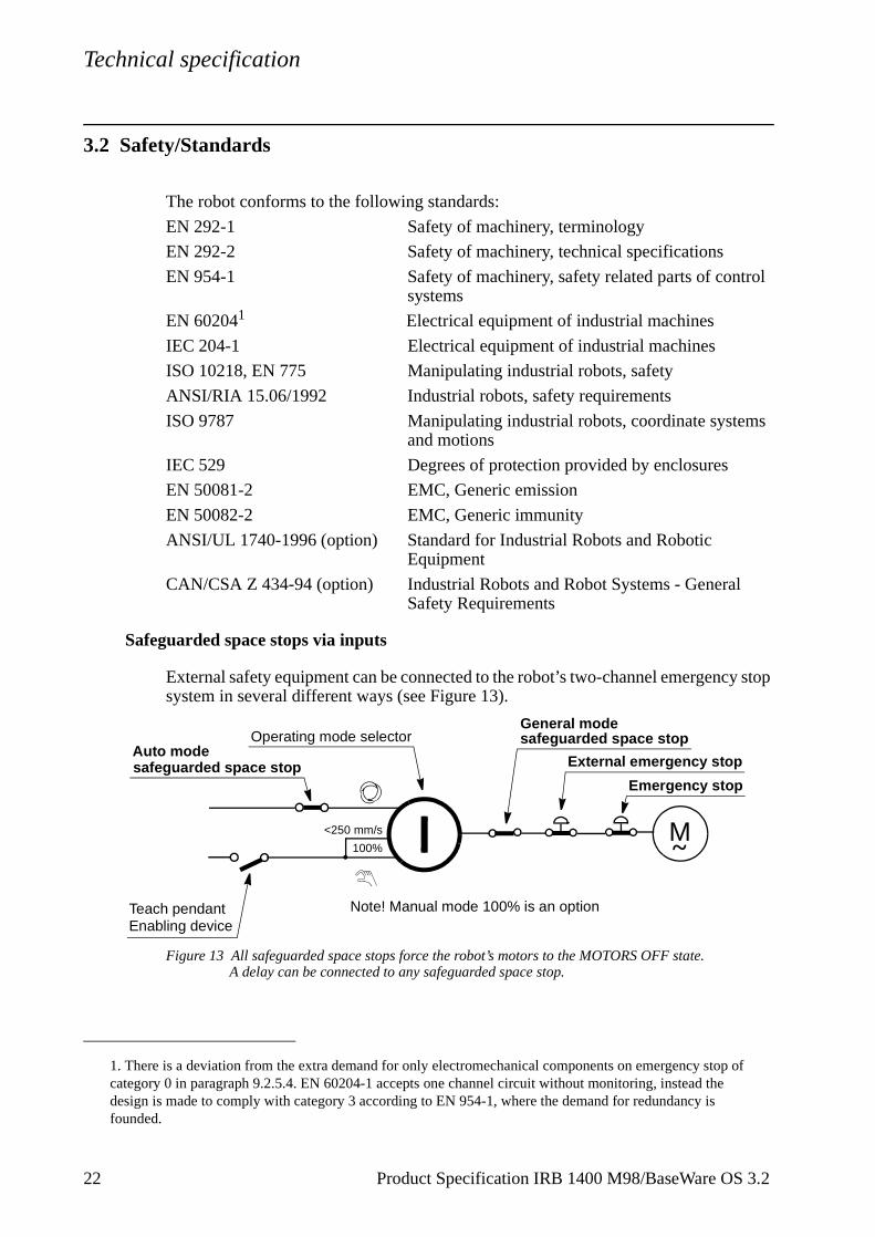
Safeguarded space stops via inputs
External safety equipment can be connected to the robot’s two-channel emergencsystem in several different ways (see Figure 13).
Figure 13 All safeguarded space stops force the robot’s motors to the MOTORS OFF state.A delay can be connected to any safeguarded space stop.
1. There is a deviation from the extra demand for only electromechanical components on emergency stop of category 0 in paragraph 9.2.5.4. EN 60204-1 accepts one channel circuit without monitoring, instead the design is made to comply with category 3 according to EN 954-1, where the demand for redundancy is founded.
<250 mm/s
100%
Emergency stop
Auto mode
General modeOperating mode selector
M~
safeguarded space stop
safeguarded space stop
Teach pendant
External emergency stop
Note! Manual mode 100% is an optionEnabling device
22 Product Specification IRB 1400 M98/BaseWare OS 3.2
Technical specification
3.3 Operation
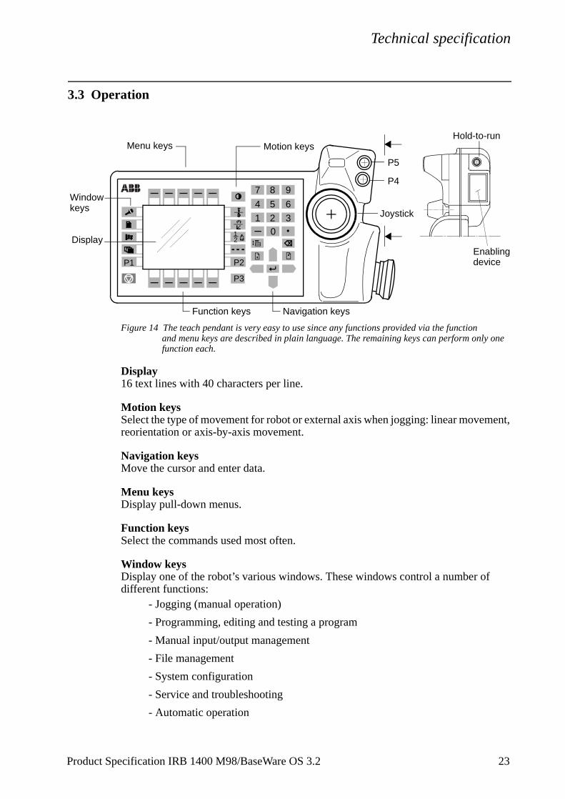
Figure 14 The teach pendant is very easy to use since any functions provided via the function and menu keys are described in plain language. The remaining keys can perform only one function each.
Display16 text lines with 40 characters per line.
Motion keysSelect the type of movement for robot or external axis when jogging: linear movement, reorientation or axis-by-axis movement.
Navigation keysMove the cursor and enter data.
Menu keysDisplay pull-down menus.
Function keysSelect the commands used most often.
Window keysDisplay one of the robot’s various windows. These windows control a number ofdifferent functions:
- Jogging (manual operation)
- Programming, editing and testing a program
- Manual input/output management
- File management
- System configuration
- Service and troubleshooting
- Automatic operation
21
2 30
1
4 5 6
7 8 9
P3
P1 P2
Hold-to-run
Enabling
P4
P5
device
Joystick
Function keys
Motion keysMenu keys
Window
Navigation keys
Display
keys
Product Specification IRB 1400 M98/BaseWare OS 3.2 23
Technical specification
User-defined keys (P1-P5)Five user-defined keys that can be configured to set or reset an output (e.g. open/close gripper) or to activate a system input (see chapter 3.10).
3.4 Installation
Operating requirements
Protection standards IEC529
Explosive environmentsThe robot must not be located or operated in an explosive environment.
Ambient temperatureManipulator during operation +5oC (41oF) to +45oC (113oF)Controller during operation +5oC (41oF) to +52oC (125oF)Complete robot during transportation and storage,-25oC (13oF) to +55oC (131oF)for short periods (not exceeding 24 hours) up to +70oC (158oF)
Relative humidityComplete robot during transportation and storageMax. 95% at constant temperatureComplete robot during operation Max. 95% at constant temperature
Power supply
Mains voltage 200-600V, 3p (3p + N for certain options), +10%,-15%
Mains frequency 48.5 to 61.8 Hz
Rated power (transformer size) 4.5 kVA - 14.4 kVA
Absolute measurement backup 1000 h (rechargeable battery)
Configuration
The robot is very flexible and can, by using the teach pendant, easily be configured to suit the needs of each user:
Authorisation Password protection for configuration and program window
Most common I/O User-defined lists of I/O signalsInstruction pick list User-defined set of instructionsInstruction builder User-defined instructionsOperator dialogs Customised operator dialogsLanguage All text on the teach pendant can be displayed in
several languagesDate and time Calendar supportPower on sequence Action taken when the power is switched onEM stop sequence Action taken at an emergency stop
24 Product Specification IRB 1400 M98/BaseWare OS 3.2
Technical specification
Product Specification IRB 1400 M98/BaseWare OS 3.2 25
Main start sequence Action taken when the program is starting from the beginning
Program start sequence Action taken at program startProgram stop sequence Action taken at program stopChange program sequence Action taken when a new program is loaded Working space Working space limitationsExternal axes Number, type, common drive unit, mechanical unitsBrake delay time Time before brakes are engagedI/O signal Logical names of boards and signals, I/O mapping,
cross connections, polarity, scaling, default value at start up, interrupts, group I/O
Serial communication Configuration
For a detailed description of the installation procedure, see the Product Manual - Installation and Commissioning.
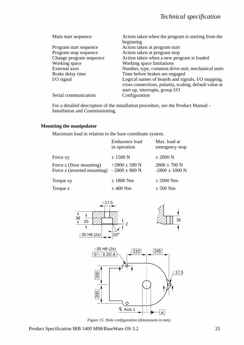
Mounting the manipulator
Maximum load in relation to the base coordinate system.
Endurance load Max. load at in operation emergency stop
Force xy ± 1500 N ± 2000 N
Force z (floor mounting) +2800 ± 500 N 2800 ± 700 NForce z (inverted mounting) - 2800 ± 800 N -2800 ± 1000 N
Torque xy ± 1800 Nm ± 2000 Nm
Torque z ± 400 Nm ± 500 Nm
Figure 15 Hole configuration (dimensions in mm).
35
245210
200
∅ 0.25 A
15o∅35 H8 (2x)
∅17,5
3820
LC Axis 1
200
2
∅17,5
∅35 H8 (2x)
A
Technical specification
Load diagram
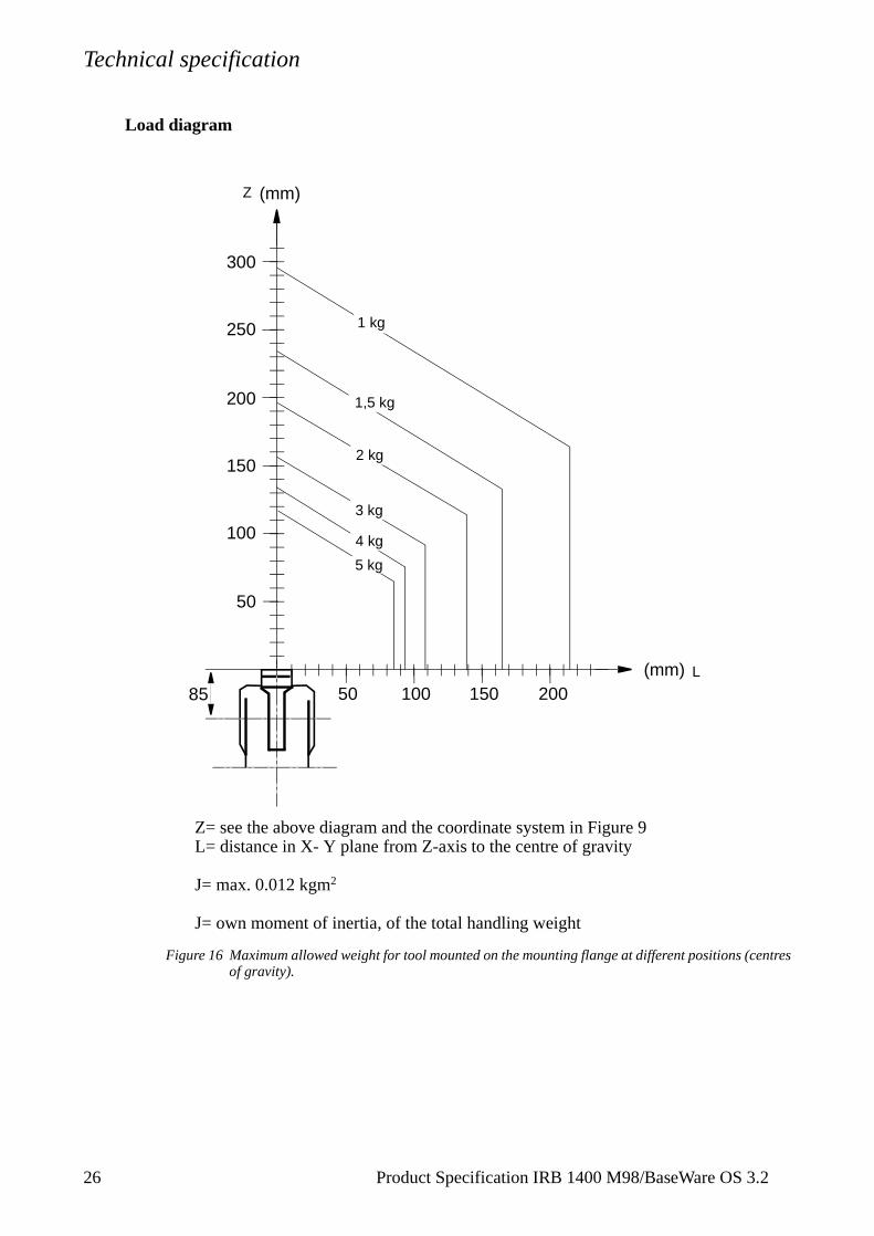
Figure 16 Maximum allowed weight for tool mounted on the mounting flange at different positions (centres of gravity).
100
200
300
100 200
2 kg
1,5 kg
(mm)
(mm)50 150
50
150
250 1 kg
3 kg
4 kg
5 kg
Z
L
Z= see the above diagram and the coordinate system in Figure 9L= distance in X- Y plane from Z-axis to the centre of gravity
J= max. 0.012 kgm2
J= own moment of inertia, of the total handling weight
85
26 Product Specification IRB 1400 M98/BaseWare OS 3.2
Technical specification
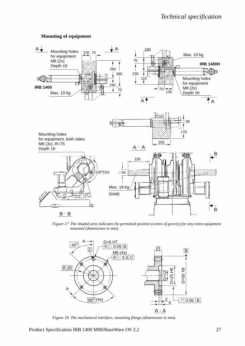
Mounting of equipment
Figure 17 The shaded area indicates the permitted position (centre of gravity) for any extra equipment mounted (dimensions in mm).
Figure 18 The mechanical interface, mounting flange (dimensions in mm).
135 70Mounting holes
260
190
380
70
A A
A A
170
30
205
Mounting holes
15o
120o(3x) ∅ 50
150
B BB
B
Max. 19 kg
(total)
Max. 10 kg IRB 1400
230
70
110
190
13570
Mounting holes
Max. 10 kg
A A
IRB 1400H
for equipmentM8 (2x)Depth 16
for equipmentM8 (2x)Depth 16
for equipment, both sidesM8 (3x), R=75Depth 16
D=
25
D=
50
H8 h8
45o D=6 H7
M6 (4x)
R 20
A
A
4
10
A - A
2
∅ 0.05
∅ 0.3
BC B
0.06 B(4x)90o
C
D=1
2
Product Specification IRB 1400 M98/BaseWare OS 3.2 27
Technical specification
2
3.5 Programming
The programming language - RAPID - is a high-level application-oriented programming language and includes the following functionality:
- hierarchial and modular structure
- functions and procedures
- global or local data and routines
- data typing, including structured and array types
- user defined names on variables, routines, inputs/outputs etc.
- extensive program flow control
- arithmetic and logical expressions
- interrupt handling
- error handling
- user defined instructions
- backward execution handler
The available sets of instructions/functions are given below. A subset of instructions to suit the needs of a particular installation, or the experience of the programmer, can be installed in pick lists. New instructions can easily be made by defining macros consisting of a sequence of standard instructions.
Note that the lists below only cover BaseWare OS. For instructions and functions associated with optional software, see Product Specification RobotWare.
Miscellaneous:= Assigns a valueWaitTime Waits a given amount of timeWaitUntil Waits until a condition is metcomment Inserts comments into the programOpMode Reads the current operating modeRunMode Reads the current program execution modeDim Gets the size of an arrayPresent Tests if an optional parameter is usedLoad Loads a program module during executionUnLoad Deletes a program module during execution
To control the program flowProcCall Calls a new procedureCallByVar Calls a procedure by a variableRETURN Finishes execution of a routineFOR Repeats a given number of timesGOTO Goes to (jumps to) a new instructionCompact IF If a condition is met, then execute one instructionIF If a condition is met, then execute a sequence of instructionslabel Line name (used together with GOTO) TEST Depending on the value of an expression ...
8 Product Specification IRB 1400 M98/BaseWare OS 3.2
Technical specification
WHILE Repeats as long as ...Stop Stops executionEXIT Stops execution when a restart is not allowedBreak Stops execution temporarily
Motion settingsAccSet Reduces the accelerationConfJ Controls the robot configuration during joint movementConfL Monitors the robot configuration during linear movementVelSet Changes the programmed velocityGripLoad Defines the payloadSingArea Defines the interpolation method through singular pointsPDispOn Activates program displacementPDispSet Activates program displacement by specifying a valueDefFrame Defines a program displacement automaticallyDefDFrame Defines a displacement frameEOffsOn Activates an offset for an external axisEOffsSet Activates an offset for an external axis using a valueORobT Removes a program displacement from a positionSoftAct Activates soft servo for a robot axisTuneServo Tunes the servo
MotionMoveC Moves the TCP circularlyMoveJ Moves the robot by joint movementMoveL Moves the TCP linearlyMoveAbsJ Moves the robot to an absolute joint positionMoveXDO Moves the robot and set an output in the end positionSearchC Searches during circular movementSearchL Searches during linear movementActUnit Activates an external mechanical unit DeactUnit Deactivates an external mechanical unitOffs Displaces a positionRelTool Displaces a position expressed in the tool coordinate systemMirPos Mirrors a positionCRobT Reads current robot position (the complete robtarget)CJointT Reads the current joint anglesCPos Reads the current position (pos data) CTool Reads the current tool dataCWObj Reads the current work object dataStopMove Stops robot motionStartMove Restarts robot motion
Input and output signalsInvertDO Inverts the value of a digital output signalPulseDO Generates a pulse on a digital output signalReset Sets a digital output signal to 0Set Sets a digital output signal to 1SetAO Sets the value of an analog output signalSetDO Sets the value of a digital output signal after a defined timeSetGO Sets the value of a group of digital output signalsWaitDI Waits until a digital input is setWaitDO Waits until a digital output is setAInput Reads the value of an analog input signalDInput Reads the value of a digital input signal
Product Specification IRB 1400 M98/BaseWare OS 3.2 29
Technical specification
3
DOutput Reads the value of a digital output signalGInput Reads the value of a group of digital input signalsGOutput Reads the value of a group of digital output signalsTestDI Tests if a digital input signal is setIODisable Disables an I/O moduleIOEnable Enables an I/O module
InterruptsISignalDI Orders interrupts from a digital input signalISignalDO Orders interrupts from a digital output signalITimer Orders a timed interruptIDelete Cancels an interruptISleep Deactivates an interruptIWatch Activates an interruptIDisable Disables interruptsIEnable Enables interruptsCONNECT Connects an interrupt to a trap routine
Error RecoveryEXIT Terminates program executionRAISE Calls an error handler RETRY Restarts following an error TRYNEXT Skips the instruction that has caused the errorRETURN Returns to the routine that called the current routine
CommunicationTPErase Erases text printed on the teach pendantTPWrite Writes on the teach pendantTPReadFK Reads function keysTPReadNum Reads a number from the teach pendantErrWrite Stores an error message in the error log
System & TimeClkReset Resets a clock used for timingClkStart Starts a clock used for timingClkStop Stops a clock used for timingClkRead Reads a clock used for timingCDate Reads the current date as a stringCTime Reads the current time as a stringGetTime Gets the current time as a numeric value
MathematicsAdd Adds a numeric valueClear Clears the valueDecr Decrements by 1Incr Increments by 1Abs Calculates the absolute valueSqrt Calculates the square rootExp Calculates the exponential value with the base “e”Pow Calculates the exponential value with an arbitrary baseACos Calculates the arc cosine valueASin Calculates the arc sine value
0 Product Specification IRB 1400 M98/BaseWare OS 3.2
Technical specification
a one
ATan/ATan2 Calculates the arc tangent valueCos Calculates the cosine valueSin Calculates the sine valueTan Calculates the tangent valueEulerZYX Calculates Euler angles from an orientationOrientZYX Calculates the orientation from Euler anglesPoseInv Inverts a posePoseMult Multiplies a posePoseVect Multiplies a pose and a vectorRound Rounds a numeric valueTrunc Truncates a numeric value
Text stringsNumToStr Converts numeric value to stringStrFind Searches for a character in a stringStrLen Gets the string lengthStrMap Maps a stringStrMatch Searches for a pattern in a stringStrMemb Checks if a character is a member of a setStrOrder Checks if strings are orderedStrPart Gets a part of a stringStrToVal Converts a string to a numeric valueValToStr Converts a value to a string
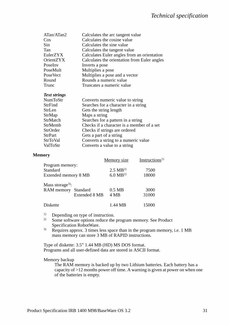
MemoryMemory size Instructions1)
Program memory:Standard 2.5 MB2) 7500Extended memory 8 MB 6.0 MB2) 18000
Mass storage3):RAM memory Standard 0.5 MB 3000
Extended 8 MB 4 MB 31000
Diskette 1.44 MB 15000
1) Depending on type of instruction.2) Some software options reduce the program memory. See Product
Specification RobotWare.3) Requires approx. 3 times less space than in the program memory, i.e. 1 MB
mass memory can store 3 MB of RAPID instructions.
Type of diskette: 3.5” 1.44 MB (HD) MS DOS format.Programs and all user-defined data are stored in ASCII format.
Memory backupThe RAM memory is backed up by two Lithium batteries. Each battery hascapacity of >12 months power off time. A warning is given at power on whenof the batteries is empty.
Product Specification IRB 1400 M98/BaseWare OS 3.2 31
Technical specification
3
3.6 Automatic Operation
The following production window commands are available:- Load/select the program.
- Start the program.
- Execute instruction-by-instruction (forward/backward).
- Reduce the velocity temporarily.
- Display program-controlled comments (which tell the operator what is happening).
- Displace a position, also during program execution (can be blocked).
3.7 Maintenance and Troubleshooting
The following maintenance is required:- Lubricating spring brackets every six months.
- Changing filter for the transformer/drive unit cooling every year.
- Greasing axes 5 and 6 every year.
- Changing batteries every third year.
The maintenance intervals depends on the use of the robot. For detailed information on maintenance procedures, see Maintenance section in the Product Manual.
2 Product Specification IRB 1400 M98/BaseWare OS 3.2
Technical specification
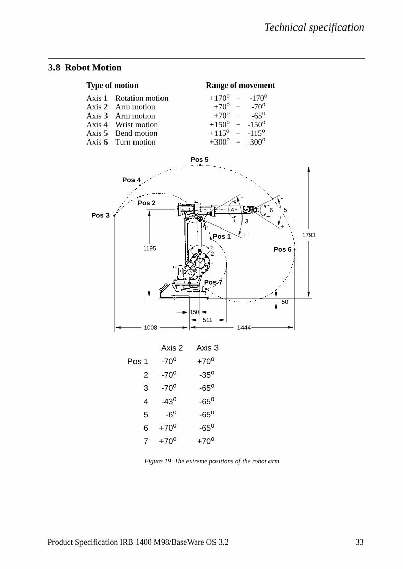
3.8 Robot Motion
Type of motion Range of movement
Axis 1 Rotation motion +170o _ -170o
Axis 2 Arm motion +70o _ -70o
Axis 3 Arm motion +70o _ -65o
Axis 4 Wrist motion +150o _ -150o
Axis 5 Bend motion +115o _ -115o
Axis 6 Turn motion +300o _ -300o
Figure 19 The extreme positions of the robot arm.
1195
1008 1444
150
511
1793
50
Pos 6
Pos 4
Pos 3
Pos 2
Pos 1
Pos 7
564
3
2+
+
+
+
+
--
- -
-
Pos 1
2
3
4
5
6
7
Axis 2 Axis 3
-43o
-70o
-6o
-35o
+70o
-70o
-70o +70o
+70o
+70o
-65o
-65o
-65o
-65o
Pos 5
Product Specification IRB 1400 M98/BaseWare OS 3.2 33
Technical specification
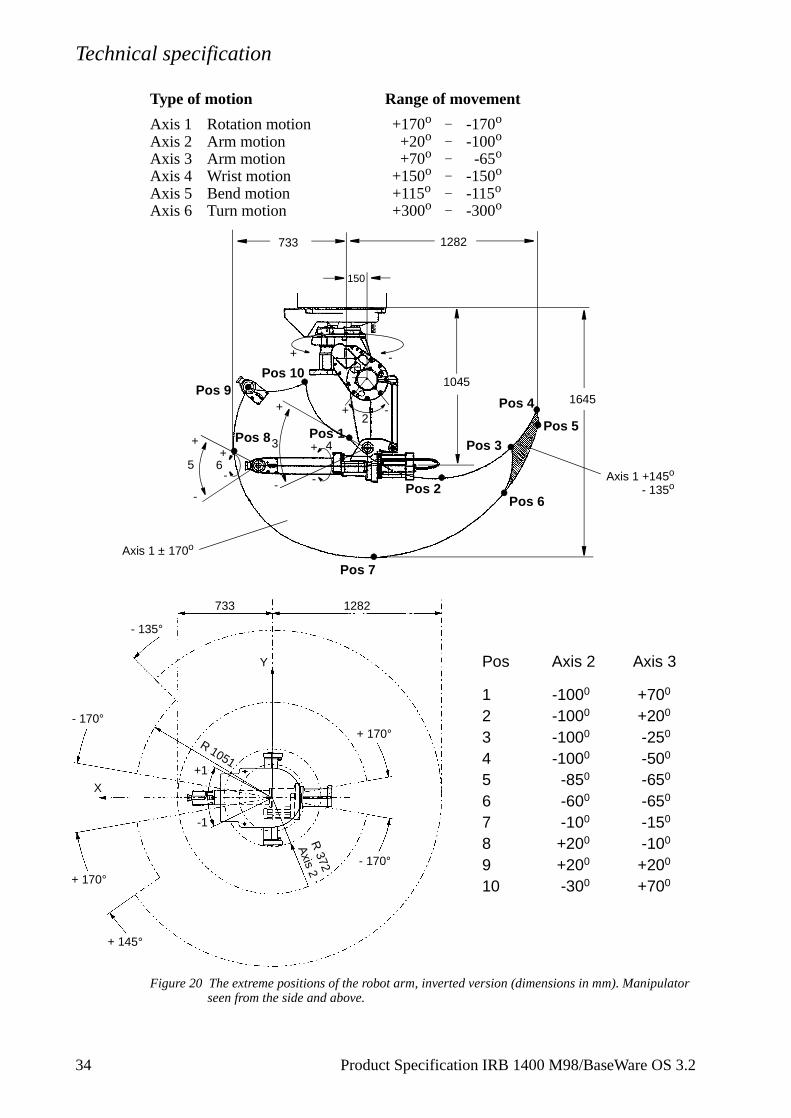
Type of motion Range of movement
Axis 1 Rotation motion +170o _ -170o
Axis 2 Arm motion +20o _ -100o
Axis 3 Arm motion +70o _ -65o
Axis 4 Wrist motion +150o _ -150o
Axis 5 Bend motion +115o _ -115o
Axis 6 Turn motion +300o _ -300o
Figure 20 The extreme positions of the robot arm, inverted version (dimensions in mm). Manipulator seen from the side and above.
1045
733 1282
150
1645
Pos 6
Pos 4
Pos 3
Pos 2
Pos 1
Pos 7
5 6
43
2+
+
+
++
-
- --
-Pos 5
Pos 8
Pos 9Pos 10
Axis 1 ± 170o
Axis 1 +145o
- 135o
+ -
R 372
Axis 2
X
Y
1282733
R 1051
- 135°
- 170°
+1
-1
+ 170°
+ 145°
- 170°
+ 170°
Pos Axis 2 Axis 3
1 -1000 +700
2 -1000 +200
3 -1000 -250
4 -1000 -500
5 -850 -650
6 -600 -650
7 -100 -150
8 +200 -100
9 +200 +200
10 -300 +700
34 Product Specification IRB 1400 M98/BaseWare OS 3.2
Technical specification
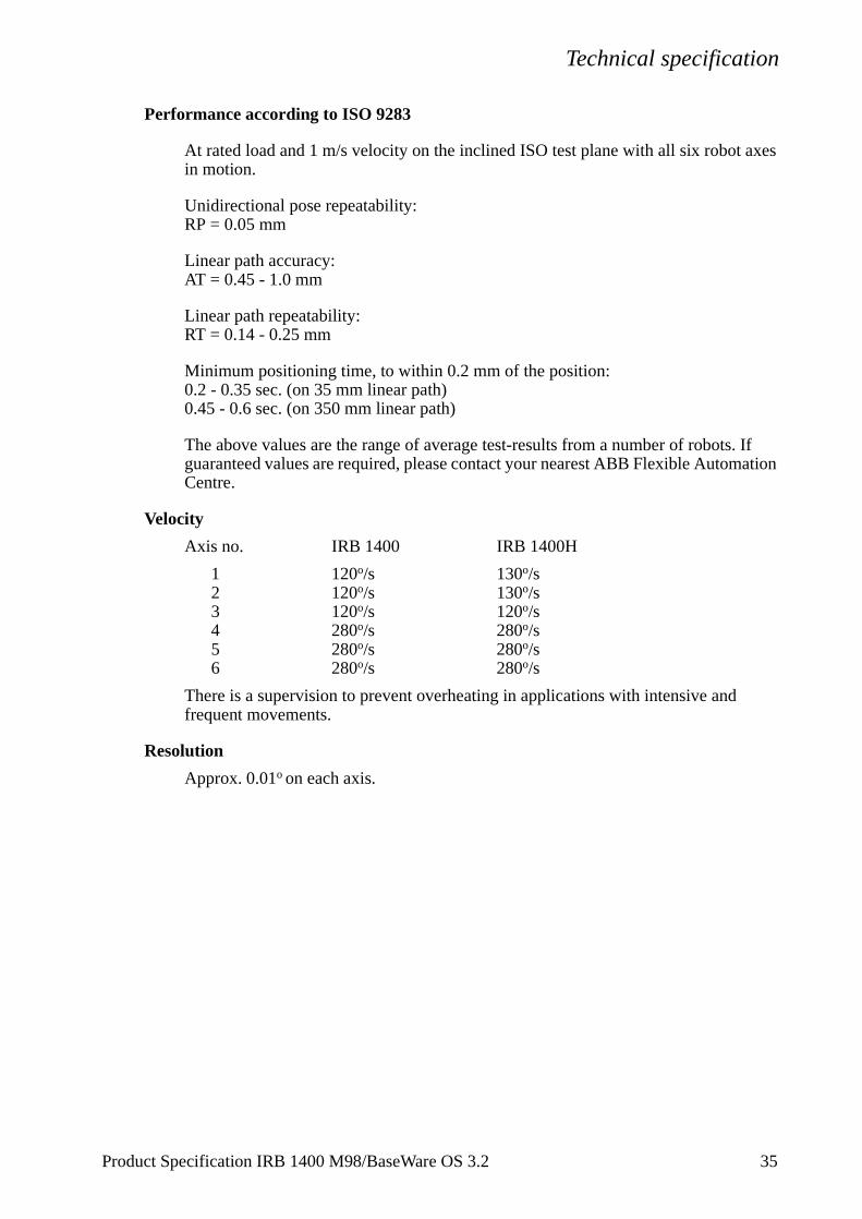
Performance according to ISO 9283
At rated load and 1 m/s velocity on the inclined ISO test plane with all six robot axes in motion.
Unidirectional pose repeatability:RP = 0.05 mm
Linear path accuracy:AT = 0.45 - 1.0 mm
Linear path repeatability:RT = 0.14 - 0.25 mm
Minimum positioning time, to within 0.2 mm of the position:0.2 - 0.35 sec. (on 35 mm linear path)0.45 - 0.6 sec. (on 350 mm linear path)
The above values are the range of average test-results from a number of robots. If guaranteed values are required, please contact your nearest ABB Flexible Automation Centre.
Velocity
Axis no. IRB 1400 IRB 1400H
1 120o/s 130o/s2 120o/s 130o/s3 120o/s 120o/s4 280o/s 280o/s5 280o/s 280o/s6 280o/s 280o/s
There is a supervision to prevent overheating in applications with intensive and frequent movements.
Resolution
Approx. 0.01o on each axis.
Product Specification IRB 1400 M98/BaseWare OS 3.2 35
Technical specification
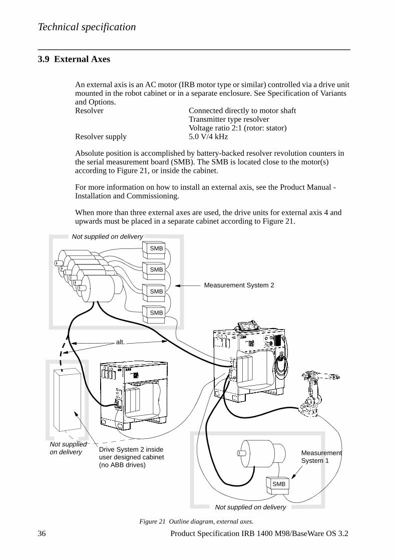
3.9 External Axes
An external axis is an AC motor (IRB motor type or similar) controlled via a drive unit mounted in the robot cabinet or in a separate enclosure. See Specification of Variants and Options.Resolver Connected directly to motor shaft
Transmitter type resolver Voltage ratio 2:1 (rotor: stator)
Resolver supply 5.0 V/4 kHz
Absolute position is accomplished by battery-backed resolver revolution counters in the serial measurement board (SMB). The SMB is located close to the motor(s) according to Figure 21, or inside the cabinet.
For more information on how to install an external axis, see the Product Manual - Installation and Commissioning.
When more than three external axes are used, the drive units for external axis 4 and upwards must be placed in a separate cabinet according to Figure 21.
Figure 21 Outline diagram, external axes.
alt.
Not supplied on delivery
Not supplied on delivery
Not supplied on delivery
Measurement System 2
Measurement System 1
Drive System 2 inside user designed cabinet(no ABB drives)
SMB
SMB
SMB
SMB
SMB
36 Product Specification IRB 1400 M98/BaseWare OS 3.2
Technical specification
3.10 Inputs and Outputs
Types of connection
The following types of connection are available:
- “Screw terminals” on the I/O units.- Serial interface for distributed I/O units.- Air and signal connections to upper arm.
For more detailed information, see Chapter 4: Specification of Variants and Options.
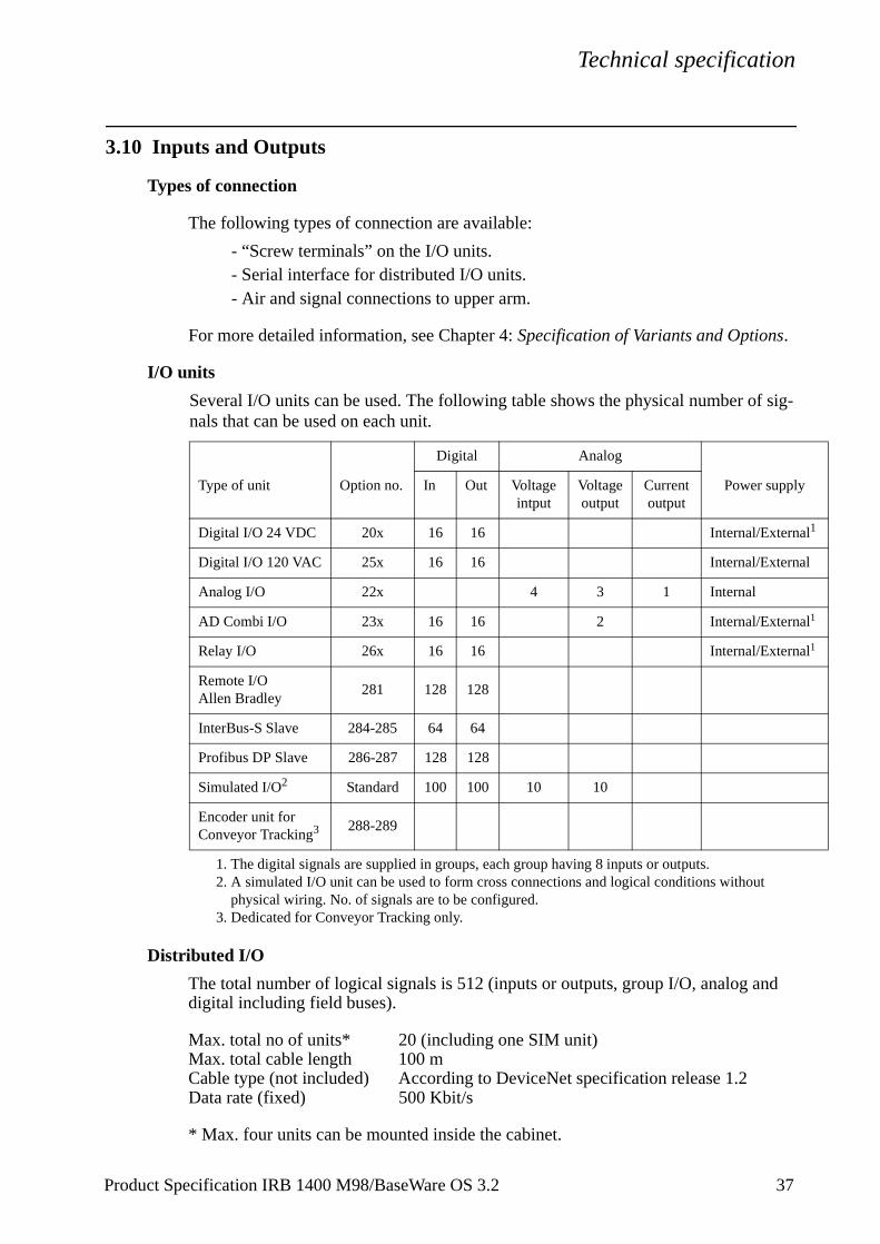
I/O units
Several I/O units can be used. The following table shows the physical number of sig-nals that can be used on each unit.
Distributed I/O
The total number of logical signals is 512 (inputs or outputs, group I/O, analog and digital including field buses).
Max. total no of units* 20 (including one SIM unit)Max. total cable length 100 mCable type (not included) According to DeviceNet specification release 1.2Data rate (fixed) 500 Kbit/s
* Max. four units can be mounted inside the cabinet.
Type of unit Option no.
Digital Analog
Power supplyIn Out Voltage intput
Voltage output
Current output
Digital I/O 24 VDC 20x 16 16 Internal/External1
1. The digital signals are supplied in groups, each group having 8 inputs or outputs.
Digital I/O 120 VAC 25x 16 16 Internal/External
Analog I/O 22x 4 3 1 Internal
AD Combi I/O 23x 16 16 2 Internal/External1
Relay I/O 26x 16 16 Internal/External1
Remote I/OAllen Bradley
281 128 128
InterBus-S Slave 284-285 64 64
Profibus DP Slave 286-287 128 128
Simulated I/O2
2. A simulated I/O unit can be used to form cross connections and logical conditions without physical wiring. No. of signals are to be configured.
Standard 100 100 10 10
Encoder unit for Conveyor Tracking3
3. Dedicated for Conveyor Tracking only.
288-289
Product Specification IRB 1400 M98/BaseWare OS 3.2 37
Technical specification
n
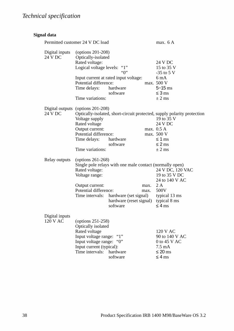
Signal data
Permitted customer 24 V DC load max. 6 A
Digital inputs (options 201-208)24 V DC Optically-isolated
Rated voltage: 24 V DCLogical voltage levels: “1” 15 to 35 V
“0” -35 to 5 VInput current at rated input voltage: 6 mAPotential difference: max. 500 VTime delays: hardware 5−15 ms
software ≤ 3 msTime variations: ± 2 ms
Digital outputs (options 201-208)24 V DC Optically-isolated, short-circuit protected, supply polarity protectio
Voltage supply 19 to 35 VRated voltage 24 V DCOutput current: max. 0.5 APotential difference: max. 500 VTime delays: hardware ≤ 1 ms
software ≤ 2 msTime variations: ± 2 ms
Relay outputs (options 261-268)Single pole relays with one male contact (normally open)Rated voltage: 24 V DC, 120 VACVoltage range: 19 to 35 V DC
24 to 140 V ACOutput current: max. 2 APotential difference: max. 500VTime intervals: hardware (set signal) typical 13 ms
hardware (reset signal) typical 8 mssoftware ≤ 4 ms
Digital inputs120 V AC (options 251-258)
Optically isolatedRated voltage 120 V ACInput voltage range: “1” 90 to 140 V ACInput voltage range: “0” 0 to 45 V ACInput current (typical): 7.5 mATime intervals: hardware ≤ 20 ms
software ≤ 4 ms
38 Product Specification IRB 1400 M98/BaseWare OS 3.2
Technical specification
Digital outputs 120 V AC (options 251-258)
Optically isolated, voltage spike protectionRated voltage 120 V ACOutput current: max. 1A/channel, 12 A
16 channels ormax. 2A/channel, 10 A
16 channels(56 A in 20 ms)
min. 30 mAVoltage range: 24 to 140 V ACPotential difference: max. 500 VOff state leakage current: max. 2mA rmsOn state voltage drop: max. 1.5 VTime intervals: hardware ≤ 12 ms
software ≤ 4 ms
Analog inputs (options 221-228)Voltage Input voltage: +10 V
Input impedance: >1 MohmResolution: 0.61 mV (14 bits)
Accuracy: +0.2% of input signal
Analog outputs (option 221-228)Voltage Output voltage: +10 V
Load impedance: min. 2 kohmResolution: 2.44 mV (12 bits)
Current Output current: 4-20 mALoad impedance: min. 800 ohmResolution: 4.88 µA (12 bits)
Accuracy: +0.2% of output signal
Analog outputs (option 231-238)Output voltage (galvanically isolated): 0 to +10 V Load impedance: min. 2 kohmResolution: 2.44 mV (12 bits)Accuracy: ±25 mV ±0.5% of output
voltagePotential difference: max. 500 VTime intervals: hardware ≤ 2.0 ms
software: ≤ 4 ms
Signal connections on robot arm
Signals 12 60 V, 500 mA
Product Specification IRB 1400 M98/BaseWare OS 3.2 39
Technical specification
.
System signals
Signals can be assigned to special system functions. Several signals can be given the same functionality.
Digital outputs Motors on/offExecutes program ErrorAutomatic modeEmergency stopRestart not possibleRestart not successfulRun chain closed
Digital inputs Motors on/offStarts program from where it isMotors on and program startStarts program from the beginningStops programStops program when the program cycle is readyStops program after current instructionExecutes “trap routine” without affecting status of stoppedregular program1 Loads and starts program from the beginning1
Resets errorResets emergency stopSystem resetSynchronizes external axes
Analog output TCP speed signal
1. Program can be decided when configuring the robot.
For more information on system signals, see User´s Guide - System Parameters
40 Product Specification IRB 1400 M98/BaseWare OS 3.2
Technical specification
3.11 Communication
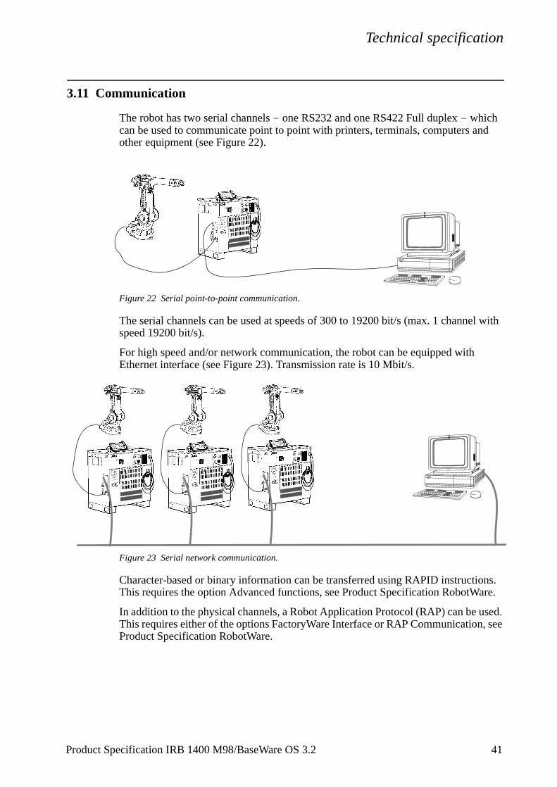
The robot has two serial channels - one RS232 and one RS422 Full duplex - which can be used to communicate point to point with printers, terminals, computers and other equipment (see Figure 22).
Figure 22 Serial point-to-point communication.
The serial channels can be used at speeds of 300 to 19200 bit/s (max. 1 channel with speed 19200 bit/s).
For high speed and/or network communication, the robot can be equipped with Ethernet interface (see Figure 23). Transmission rate is 10 Mbit/s.
Figure 23 Serial network communication.
Character-based or binary information can be transferred using RAPID instructions. This requires the option Advanced functions, see Product Specification RobotWare.
In addition to the physical channels, a Robot Application Protocol (RAP) can be used. This requires either of the options FactoryWare Interface or RAP Communication, see Product Specification RobotWare.
Product Specification IRB 1400 M98/BaseWare OS 3.2 41
Technical specification
42 Product Specification IRB 1400 M98/BaseWare OS 3.2
Specification of Variants and Options
to the
.
4 Specification of Variants and Options
The different variants and options for the IRB 1400 are described below.The same numbers are used here as in the Specification form.For software options, see Product Specification RobotWare.
Note Options marked with * are inconsistent with UL/UR approval.
1 MANIPULATOR
VARIANTS
021 IRB 1400For floor mounting.
022 IRB 1400HFor inverted mounting.
Manipulator colour
The manipulator is painted with ABB orange if no colour is specified.
08A- Colours according to RAL-codes.08V
APPLICATION INTERFACE
Air supply and signals for extra equipment to upper arm
04y Hose for compressed air is integrated into the manipulator. There is an inlet at the base and an outlet on the upper arm housing.
Connections: R1/4” in the upper arm housing and at the base. Max. 8 bar.Inner hose diameter: 6.5 mm.
For connection of extra equipment on the manipulator, there are cables integrated inmanipulator’s cabling.
Number of signals: 12 signals 49 V, 500 mA.Connector on upper arm: Burndy 12-pin UTG 014-12SConnector on robot base: Burndy 12-pin UTG 014-12P
044 Control cabling to arc welding wire-feeder is integrated into the manipulator’s cabling
Control signals: 16 signals, 49 V, 500 mAConnector on upper arm housing: Burndy 23-pin UTG 618-23PNConnector on robot base: Burndy 23-pin socket UT001823SHT
Power signals: 12 signals, 300 V, 4 AConnector on upper arm housing: Burndy 12-pin socket UTG 614-12SN
Product Specification IRB 1400 M98/BaseWare OS 3.2 43
Specification of Variants and Options
Connector on robot base: Burndy 12-pin UT001412PHT
This option is not available for IRB 1400H and not together with 67A-D/671-674
CONNECTION OF SIGNALS
Internal or external connection is ordered by the choice of manipulator cable, options 641-644 and 651-656.
045 The signals are connected directly to the robot base. The cable from the manipulator to the controller is not supplied.
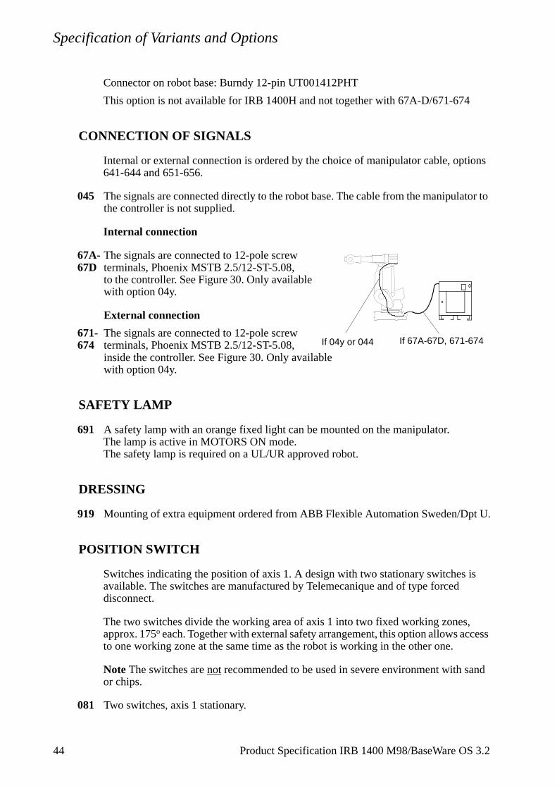
Internal connection
67A- The signals are connected to 12-pole screw 67D terminals, Phoenix MSTB 2.5/12-ST-5.08,
to the controller. See Figure 30. Only available with option 04y.
External connection
671- The signals are connected to 12-pole screw 674 terminals, Phoenix MSTB 2.5/12-ST-5.08,
inside the controller. See Figure 30. Only available with option 04y.
SAFETY LAMP
691 A safety lamp with an orange fixed light can be mounted on the manipulator.The lamp is active in MOTORS ON mode.The safety lamp is required on a UL/UR approved robot.
DRESSING
919 Mounting of extra equipment ordered from ABB Flexible Automation Sweden/Dpt U.
POSITION SWITCH
Switches indicating the position of axis 1. A design with two stationary switches is available. The switches are manufactured by Telemecanique and of type forced disconnect.
The two switches divide the working area of axis 1 into two fixed working zones, approx. 175o each. Together with external safety arrangement, this option allows access to one working zone at the same time as the robot is working in the other one.
Note The switches are not recommended to be used in severe environment with sand or chips.
081 Two switches, axis 1 stationary.
If 04y or 044 If 67A-67D, 671-674
44 Product Specification IRB 1400 M98/BaseWare OS 3.2
Specification of Variants and Options
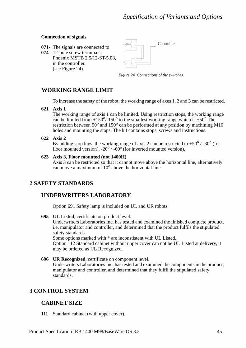
Connection of signals
071- The signals are connected to 074 12-pole screw terminals,
Phoenix MSTB 2.5/12-ST-5.08,in the controller.(see Figure 24).
Figure 24 Connections of the switches.
WORKING RANGE LIMIT
To increase the safety of the robot, the working range of axes 1, 2 and 3 can be restricted.
621 Axis 1The working range of axis 1 can be limited. Using restriction stops, the working range can be limited from +150o/-150o to the smallest working range which is +50o The restriction between 50o and 150o can be performed at any position by machining M10 holes and mounting the stops. The kit contains stops, screws and instructions.
622 Axis 2By adding stop lugs, the working range of axis 2 can be restricted to +50o / -30o (for floor mounted version), -20o / -60o (for inverted mounted version).
623 Axis 3, Floor mounted (not 1400H)Axis 3 can be restricted so that it cannot move above the horizontal line, alternatively can move a maximum of 10o above the horizontal line.
2 SAFETY STANDARDS
UNDERWRITERS LABORATORY
Option 691 Safety lamp is included on UL and UR robots.
695 UL Listed, certificate on product level.Underwriters Laboratories Inc. has tested and examined the finished complete product, i.e. manipulator and controller, and determined that the product fulfils the stipulated safety standards.Some options marked with * are inconstistent with UL Listed.Option 112 Standard cabinet without upper cover can not be UL Listed at delivery, it may be ordered as UL Recognized.
696 UR Recognized, certificate on component level.Underwriters Laboratories Inc. has tested and examined the components in the product, manipulator and controller, and determined that they fulfil the stipulated safetystandards.
3 CONTROL SYSTEM
CABINET SIZE
111 Standard cabinet (with upper cover).
Controller
Product Specification IRB 1400 M98/BaseWare OS 3.2 45
Specification of Variants and Options
112 Standard cabinet without upper cover. To be used when cabinet extension is mounted on top of the cabinet after delivery.This option is inconsistent with UL approval (option 695 UL Listed).
114 With extended cover 250 mm.The height of the cover is 250 mm, which increases the available space for external equipment that can be mounted inside the cabinet.This option is inconsistent with UL approval (option 695 UL Listed).
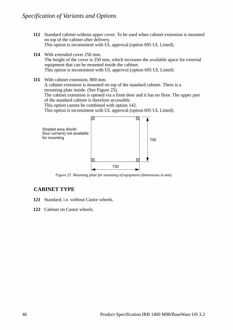
115 With cabinet extension, 800 mm.A cabinet extension is mounted on top of the standard cabinet. There is a mounting plate inside. (See Figure 25).The cabinet extension is opened via a front door and it has no floor. The upper part of the standard cabinet is therefore accessible.This option cannot be combined with option 142.This option is inconsistent with UL approval (option 695 UL Listed).
Figure 25 Mounting plate for mounting of equipment (dimensions in mm).
CABINET TYPE
121 Standard, i.e. without Castor wheels.
122 Cabinet on Castor wheels.
Shaded area 40x40 (four corners) not available
705
730
for mounting
46 Product Specification IRB 1400 M98/BaseWare OS 3.2
Specification of Variants and Options
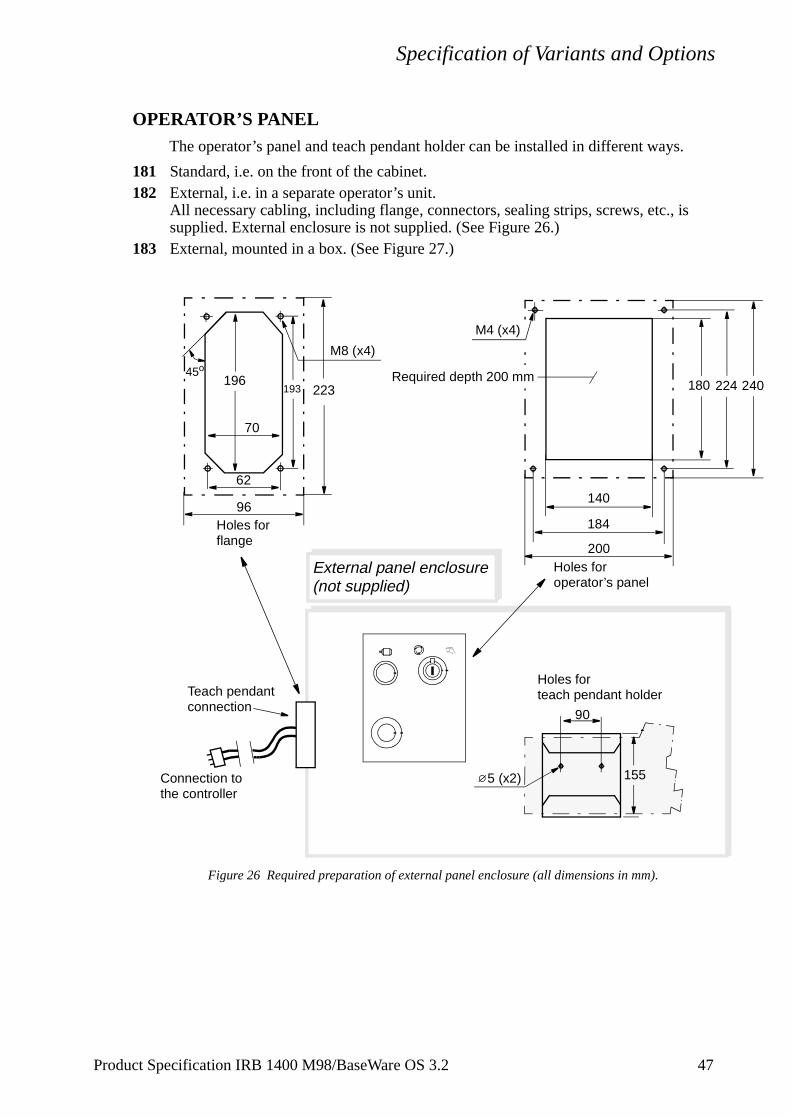
OPERATOR’S PANELThe operator’s panel and teach pendant holder can be installed in different ways.
181 Standard, i.e. on the front of the cabinet.182 External, i.e. in a separate operator’s unit.
All necessary cabling, including flange, connectors, sealing strips, screws, etc., is supplied. External enclosure is not supplied. (See Figure 26.)
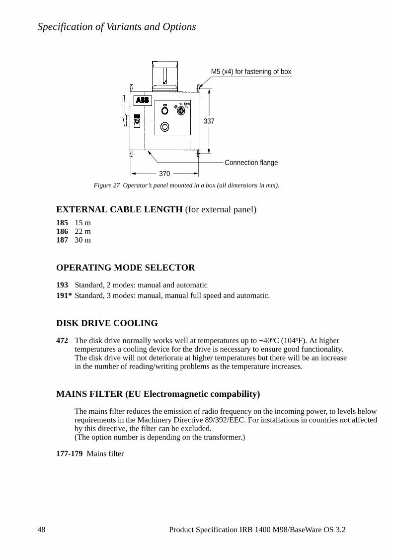
183 External, mounted in a box. (See Figure 27.)
Figure 26 Required preparation of external panel enclosure (all dimensions in mm).
184
224180
140
193196
70
62
45o
External panel enclosure(not supplied)
M8 (x4)
Connection to
Holes for flange
Holes for operator’s panel
Holes forteach pendant holder
the controller
90
1555 (x2)
Teach pendantconnection
200
240Required depth 200 mm
M4 (x4)
96
223
Product Specification IRB 1400 M98/BaseWare OS 3.2 47
Specification of Variants and Options
Figure 27 Operator’s panel mounted in a box (all dimensions in mm).
EXTERNAL CABLE LENGTH (for external panel)
185 15 m186 22 m187 30 m
OPERATING MODE SELECTOR
193 Standard, 2 modes: manual and automatic191* Standard, 3 modes: manual, manual full speed and automatic.
DISK DRIVE COOLING
472 The disk drive normally works well at temperatures up to +40oC (104oF). At higher temperatures a cooling device for the drive is necessary to ensure good functionality. The disk drive will not deteriorate at higher temperatures but there will be an increase in the number of reading/writing problems as the temperature increases.
MAINS FILTER (EU Electromagnetic compability)
The mains filter reduces the emission of radio frequency on the incoming power, to levels below requirements in the Machinery Directive 89/392/EEC. For installations in countries not affected by this directive, the filter can be excluded.(The option number is depending on the transformer.)
177-179 Mains filter
337
370
M5 (x4) for fastening of box
Connection flange
48 Product Specification IRB 1400 M98/BaseWare OS 3.2
Specification of Variants and Options
hand part)
DOOR KEYS461 Standard
462 DIN 3 mm
463 Square outside 7 mm
465 EMKA
MAINS VOLTAGEThe robot can be connected to a rated voltage of between 200 V and 600 V, 3-phase and protective earthing. A voltage fluctuation of +10% to -15% is permissible in each connection.
151- Voltage Voltage Voltage
174 200 V220 V 400 V 400 V440 V 440 V
475 V 475 V500 V 500 V
525 V600 V
CONNECTION OF MAINS
The power is connected either inside the cabinet or to a connector on the cabinet’s left-side. The cable is not supplied. If option 132-133 is chosen, the female connector (cableis included.
131 Cable gland for inside connection. Diameter of cable:11-12 mm.
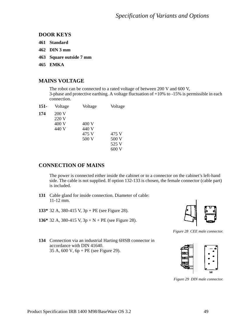
133* 32 A, 380-415 V, 3p + PE (see Figure 28).
136* 32 A, 380-415 V, 3p + N + PE (see Figure 28).
Figure 28 CEE male connector.
134 Connection via an industrial Harting 6HSB connector in accordance with DIN 41640.35 A, 600 V, 6p + PE (see Figure 29).
Figure 29 DIN male connector.
Product Specification IRB 1400 M98/BaseWare OS 3.2 49
Specification of Variants and Options
MAINS SWITCH
141* Rotary switch in accordance with the standard in section 3.2 and IEC 337-1, VDE 0113.
142 Rotary switch with door interlock.
143 Flange disconnect in accordance with the standard in section 3.2. Includes door interlock.
144 Rotary switch with door interlock and servo disconnector.This option adds a mechanical switch to the two series connected motors on contactors. The switch is operated by the same type of handle as the rotary mains switch. The handle can be locked by a padlock, e.g. in an off position.
147/149 Circuit breaker for the option rotary switch. A 16 A (147) or 25 A (149) circuit breaker for short circuit protection of main cables in the cabinet. Circuit breaker approved in accordance with IEC 898, VDE 0660. (The option number is depending on the transformer.)
14B Fuses (3x15 A) for the option Rotary switch for short circuit protection of main cables in the cabinet. Interrupt capacity: 50 kA.
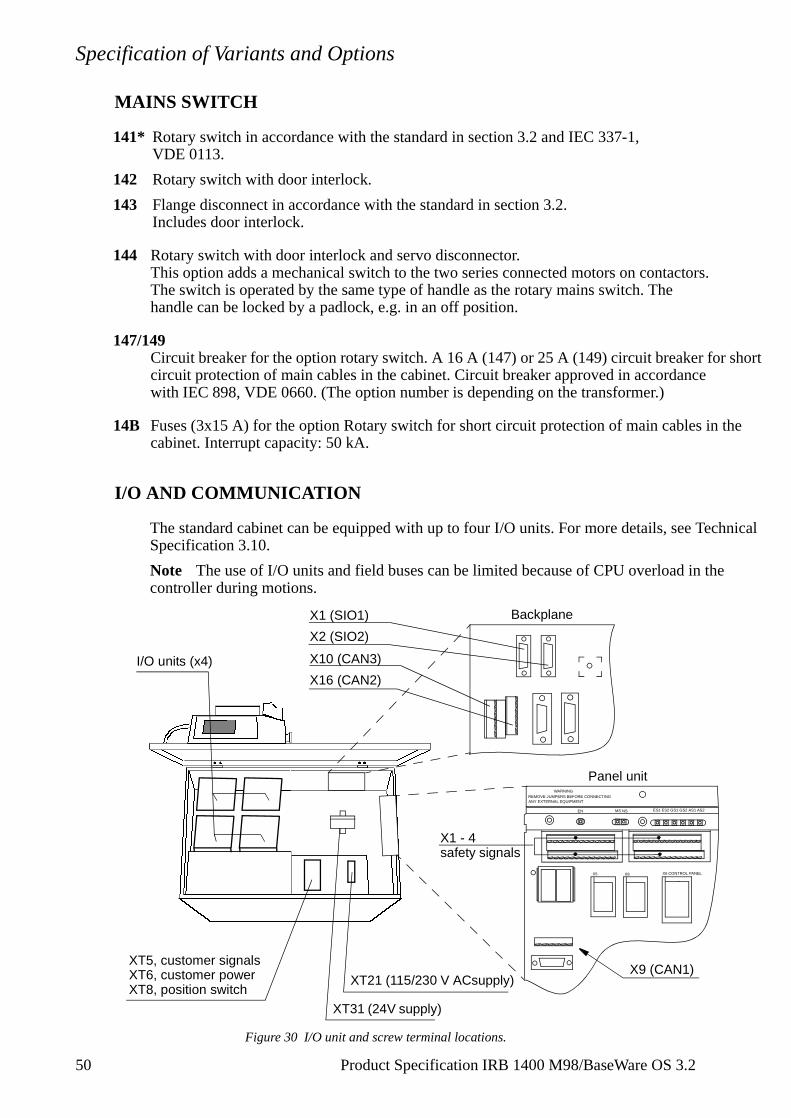
I/O AND COMMUNICATION
The standard cabinet can be equipped with up to four I/O units. For more details, see Technical Specification 3.10.
Note The use of I/O units and field buses can be limited because of CPU overload in the controller during motions.
Figure 30 I/O unit and screw terminal locations.
I/O units (x4)
XT5, customer signalsXT6, customer powerXT8, position switch
XT31 (24V supply)
Backplane
X10 (CAN3)
X16 (CAN2)
X1 (SIO1)
X2 (SIO2)
X5 X8 X6 CONTROL PANEL
WARNINGREMOVE JUMPERS BEFORE CONNECTINGANY EXTERNAL EQUIPMENT
EN MS NS ES1 ES2 GS1 AS2AS1GS2
Panel unit
X1 - 4safety signals
XT21 (115/230 V ACsupply)X9 (CAN1)
50 Product Specification IRB 1400 M98/BaseWare OS 3.2
Specification of Variants and Options
CABINET I/O MODULES
201-208 Digital 24 VDC I/O: 16 inputs/16 outputs.
221-228 Analog I/O: 4 inputs/4 outputs.
231-238 AD Combi I/O: 16 digital inputs/16 digital outputs and 2 analog outputs (0-10V).
251-258 Digital 120 VAC I/O 16 inputs/16 outputs.
261-268 Digital I/O with relay outputs: 16 inputs/16 outputs. Relay outputs to be used when more current or voltage is required from the digital outputs. The inputs are not separated by relays.
Connection of I/O:
301 Internal connection (options 201-204, 221-224, 231-234, 251-254, 261-264)The signals are connected directly to screw terminals on the I/O units in the upper part of the cabinet (see Figure 30).
305 External connection Standard industrial connectors, 64-pin/socket plugs in accordance with DIN 43652, located on the left-hand side of the cabinet. Corresponding cable connectors are also supplied.
FIELD BUSES MOUNTED IN CABINET
For more details, see Technical Specification 3.9.
281 Allen-Bradley Remote I/O SlaveUp to 128 digital inputs and 128 digital outputs, in groups of 32, can be transferred serially to a PLC equipped with an Allen-Bradley 1771 RIO node adapter. The unit reduces the number of I/O units that can be mounted in cabinet by one. The field bus cables are connected directly to the screw terminals on the A-B RIO unit in the upper part of the cabinet (see Figure 30).
284/285InterBus-S SlaveUp to 64 digital inputs and 64 digital outputs per unit, in groups of 16, can be transferred serially to a PLC equipped with an InterBus-S interface. The unit reduces the number of I/O units that can be mounted in cabinet by one. The signals are connected directly to the InterBus-S-slave unit (two 9-pole D-sub) in the upper part of the cabinet, and to a 5-pole screw connector.
286/287Profibus DP SlaveUp to 128 digital inputs and 128 digital outputs per unit, in groups of 16, can be transferred serially to a PLC equipped with a Profibus DP interface. The unit reduces the number of I/O units that can be mounted in cabinet by one. The signals are connected directly to the Profibus DP slave unit (one 9-pole D-sub) in the upper part of the cabinet, and to a 5-pole screw connector.
288/289Encoder interface unit for conveyor tracking Conveyor Tracking, or Line Tracking, is the function whereby the robot follows a work object which is mounted on a moving conveyor. The encoder and synchronization
Product Specification IRB 1400 M98/BaseWare OS 3.2 51
Specification of Variants and Options
switch cables are connected directly to the encoder unit in the upper part of the cabinet(see Figure 30). Screw connector is included. For more information see Product Specification RobotWare.
CONNECTION OF SAFETY SIGNALS
381 Internal The signals are connected directly to screw terminals (X1-X4) in the upper part of the cabinet (see Figure 30).
382 ExternalStandard industrial connectors, 64-pin plugs in accordance with DIN 43652, located on the left-hand side of the cabinet. Corresponding cable connectors are also supplied.
ADDITIONAL UNITS
I/O units can be delivered separately. The units can then be mounted outside the cabinet or in the cabinet extension. These are connected in a chain to a connector (CAN 3 or CAN 2, see Figure 30) in the upper part of the cabinet. Connectors to the I/O units and a connector to the cabinet (Phoenix MSTB 2.5/xx-ST-5.08), but no cabling, is included. Measures according to Figure 31 and Figure 32. For more details, see Technical Specification 3.9.
68 A-F Digital I/O 24 V DC: 16 inputs/16 outputs.
68 G-H Analog I/O.
68 I-L AD Combi I/O: 16 digital inputs/16 digital outputs and 2 analog outputs (0-10V).
68 M-P Digital I/O 120 V AC: 16 inputs/16 outputs.
68 Q-T Digital I/O with relay outputs: 16 inputs/16 outputs.
68 U Allen-Bradley Remote I/O
68 V-X Interbus-S Slave
68 Y-Z Profibus DP Slave
69 A-B Encoder interface unit for conveyor tracking
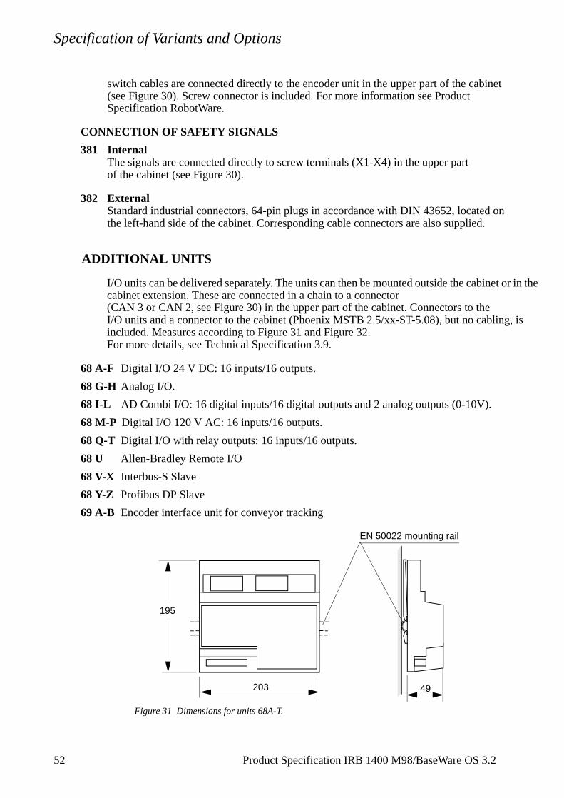
Figure 31 Dimensions for units 68A-T.
195
203 49
EN 50022 mounting rail
52 Product Specification IRB 1400 M98/BaseWare OS 3.2
Specification of Variants and Options
ween
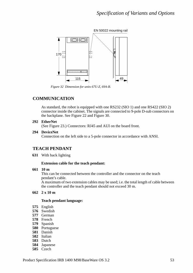
Figure 32 Dimension for units 67U-Z, 69A-B.
COMMUNICATION
As standard, the robot is equipped with one RS232 (SIO 1) and one RS422 (SIO 2) connector inside the cabinet. The signals are connected to 9-pole D-sub connectors on the backplane. See Figure 22 and Figure 30.
292 EtherNet (See Figure 23.) Connectors: RJ45 and AUI on the board front.
294 DeviceNetConnection on the left side to a 5-pole connector in accordance with ANSI.
TEACH PENDANT631 With back lighting
Extension cable for the teach pendant:
661 10 mThis can be connected between the controller and the connector on the teach pendant’s cable.A maximum of two extension cables may be used; i.e. the total length of cable betthe controller and the teach pendant should not exceed 30 m.
662 2 x 10 m
Teach pendant language:
575 English576 Swedish577 German578 French579 Spanish580 Portuguese581 Danish582 Italian583 Dutch584 Japanese585 Czech
49115
170
EN 50022 mounting rail
Product Specification IRB 1400 M98/BaseWare OS 3.2 53
Specification of Variants and Options
EXTERNAL AXES
Drive unit mounted in cabinet
The controller is equipped with drives for external axes.The motors are connected to a standard industrial 64-pin female connector, in accordance with DIN 43652, on the left-hand side of the cabinet. (Male connector is also supplied.)The transformer 4.5 kVA is replaced with 7.2 kVA, and the DC-link size DC1 is replaced with DC2.
391 Drive unit TThe drive unit is part of the DC-link. Recommended motor type see Figure 33.
392 Drive unit GTA separate drive unit including two drives. Recommended motor types see Figure 33.
394 Drive unit T+GTA combination of 391 and 392.
395 Drive unit CThe drive unit is part of the DC-link. Recommended motor type see Figure 33.
396 Drive unit C+GTA combination of 395 and 392.
398 Prepared for GTNo drive units or cables are included, only transformer 7.2 kVA and DC link DC2.
EXTERNAL AXES MEASUREMENT BOARDThe resolver can either be connected to a serial measurement board outside the controller, or to a measurement board inside the cabinet.
386 Serial measurement board inside cabinetSignal interface to external axes with absolute position at power on. The board is located in the cabinet and occupies one I/O unit slot. The resolvers are connected to a standard industrial 64-pin connector in accordance with DIN 43652, on the left-hand side of the cabinet.
387 Serial measurement board as separate unit
24 V POWER SUPPLY
As standard, the 24 V supply to the serial measurement board disappears almost momentarily at a power failure. To allow position control of external high speed (> 3000 rpm) motors during the power failure braking intervals, a power supply unit with extended 24 V capacity can be installed.
39A Standard power supply unit
39B Extended power supply unit
54 Product Specification IRB 1400 M98/BaseWare OS 3.2

Specification of Variants and Options
EXTERNAL AXES - SEPARATE CABINET
If more external axes than in option 390 are to be used, an external cabinet can be supplied. The external cabinet is connected to one Harting connector (cable length 7 m) on the left-hand side of the robot controller.
Door interlock, mains connection, mains voltage and mains filter according to the robot controller. One transformer 7.2 kVA, and one mains switch are included.
37N-O Drive unit GT, for 4, or 6 motors. Recommended motor types see Figure 33.
37Q Drive unit ECB, for 3 or 6 motors. Recommended motor types see Figure 33.
37V Drive unit GT + ECB
37X Drive unit GT + GT + ECB
Figure 33 Motor selecting table.
EQUIPMENT
Manipulator cable, internal connectors
641- The cables are connected directly to the drive units inside the cabinet via a cable 644 gland on the left-hand side of the controller.
Manipulator cable, external connection
651- The cables are connected to 64-pin standard industrial connectors in accordance with 654 DIN 43652, located on the left-hand side of the controller and on the base of the
manipulator.
655 7 m, metal braided 656 15 m, metal braided
SERVICE OUTLET
Drive unit data Max current Rated current Motor type1
1. Motors from ABB Flexible Automation/System Products.Types: S=small (TN=1,7 Nm), M=medium (TN=5 Nm), L=large (TN=12 Nm)
U 11 - 55A rms 24A rms M, L
G 6 - 30A rms 16A rms S, M, L
T 7,5 - 37A rms 20A rms S, M, L
E 4 - 19A rms 8,4A rms
C 2,5 - 11A rms 5A rms
B 1,5 - 7A rms 4A rms
Product Specification IRB 1400 M98/BaseWare OS 3.2 55
Specification of Variants and Options
Any of the following standard outlets with protective earthing can be chosen for maintenance purposes.The maximum load permitted is 500 VA (max. 100 W can be installed inside the cabinet).
421* 230 V mains outlet in accordance with DIN VDE 0620; single socket suitable for Sweden, Germany and other countries.
422* 230 V in accordance with French standard; single socket.
423* 120 V in accordance with British standard; single socket.
424 120 V in accordance with American standard; single socket, Harvey Hubble.
425* Service outlet according to 421 and a computer connection on the front of the cabinet. The computer connection is connected to the RS232 serial channel.
POWER SUPPLY
431 Connection from the main transformer.The voltage is switched on/off by the mains switch on the front of the cabinet.
432 Connection before mains switch without transformer.Note this only applies when the mains voltage is 400 V, three-phase with neutralconnection and a 230 V service socket.Note! Connection before mains switch is not in compliance with some nationalstandards, NFPL 79 for example.
433 Connection before mains switch with an additional transformer for line voltages 400-500 V and with a secondary voltage of 115 V or 230 V, 2A.Note! Connection before mains switch is not in compliance with some nationalstandards, NFPL 79 for example.
439 Earth fault protectionTo increase personal safety, the service outlet can be supplied with an earth fault protection which trips at 30 mA earth current. The earth fault protection is placed next to the service outlet (see Figure 30). Voltage range: 110 - 240 V AC.
RAM MEMORY
402 Standard, total memory 8+8 MB
403 Extended memory, total 8+16 MB
EXTRA DOCUMENTATION
Product Manuals
G11-G13 EnglishG21-G23 SwedishG31-G33 German
56 Product Specification IRB 1400 M98/BaseWare OS 3.2
Specification of Variants and Options
G41-G43 FrenchG51-G53 SpanishG61-G63 PortugueseG71-G73 DanishG81-G83 ItalianG91-G93 Dutch
Product Specification IRB 1400 M98/BaseWare OS 3.2 57

Specification of Variants and Options
58 Product Specification IRB 1400 M98/BaseWare OS 3.2
Accessories
5 Accessories
There is a range of tools and equipment available, specially designed for the robot.
Software options for robot and PC
For more information, see Product Specification RobotWare.
Robot Peripherals
- Track Motion
- Tool System
- Motor Units
Product Specification IRB 1400 M98/BaseWare OS 3.2 57

Accessories
58 Product Specification IRB 1400 M98/BaseWare OS 3.2
Index
6 Index
A
absolute measurement 12accessories 57air supply 43Allen-Bradley Remote I/O 17, 37, 51analog signals 17, 39arithmetic 28automatic mode 9automatic operation 12, 32
B
backupabsolute measurement 24memory 31
BaseWare OS 3battery 31
C
cabinet extension 19, 46cabinet wheels 46communication 18, 41concurrent I/O 17configuration 9, 17, 24connection 56
mains supply 49cooling device 19coordinate systems 15cross connections 17cursor 7
D
data typing 28DeviceNet 53diagnostics 13digital signals 17, 38diskette 31display 7, 23door keys 49drive units 54
E
editing
Product Specification IRB 1400 M98/BaseWare
position 11programs 11
emergency stop 6, 7emergency stop system 22enabling device 6, 7Encoder interface unit 37, 51equipment
mounting 27permitted extra load 27
error handling 28event routine 12execution handler 28extended cover 19, 46extended memory 31external axes 17, 36external panel 47extra equipment
connections 43
F
fire safety 7fly-by point 10function keys 23functions 28
H
hold-to-run control 7humidity 24
I
I/O 17, 37I/O units 37incremental jogging 16inputs 17, 37installation 9, 24instructions 28Interbus-S Slave 37, 51interrupt 17interrupt handling 28
J
jogging 16joystick 8
OS 3.2 59
Index
6
L
language 24lighting
connection 56teach pendant 53
load 9, 25load diagrams 26logical expressions 28
M
mains supply 49mains switch 50mains voltage 48, 49maintenance 12, 32manipulator cable 55manual mode 9mechanical interface 27memory
backup 31extended 31mass storage 31RAM memory 31
menu keys 23mirroring 11motion 14, 33motion keys 23motion performance 15mounting
extra equipment 27robot 25
mounting flange 27Multitasking 18
N
navigation keys 23noise level 19
O
operating mode 8operating mode selector 48operating requirements 24operation 7, 23operator dialogs 24operator’s panel 47options 43
0 Product Sp
outputs 17, 37overspeed protection 6
P
password 11, 24payload 9performance 15, 35PLC functionality 17position
editing 11execution 16programming 10, 16
position fixed I/O 17position switch 44power supply 24printer 10production window 12Profibus DP Slave 37, 51program
editing 11testing 11
program displacement 29program flow control 28program storage 31programming 9, 28programming language 28protection standards 24
Q
QuickMove 15
R
range of movementworking space 33
RAPID 28reduced speed 6repeatability 35robot motion 33Robot Peripherals 57robot versions 3, 43
S
safeguarded space stop 6, 22delayed 6, 22
ecification IRB 1400 M98/BaseWare OS 3.2
Index
safety 6, 22safety lamp 7, 44serial communication 18service 12service outlets 55, 56service position indicator 44signal connections 39, 43signal data 38singular points 15soft servo 29space requirements 19standards 6, 22stationary TCP 16stop point 10structure 5, 19system signals 40
T
TCP 15teach pendant 7, 23teach pendant cable 53teach pendant lighting 53temperature 24testing programs 11transformer 49trap routines 17troubleshooting 12TrueMove 15
U
UL approved 22user-defined keys 24
V
variants 43volume 19
W
weight 19window keys 23windows 7working space
restricting 7, 45
Product Specification IRB 1400 M98/BaseWare
OS 3.2 61
Index
6
2 Product Specification IRB 1400 M98/BaseWare OS 3.2