product information vegavib 61 - 63 / vegawave 61 -...
TRANSCRIPT

Level detectionof bulk solidsVibration
VEGAVIB 61 - 63VEGAWAVE 61 -63
Product Information
Contents
2 Vibration – Level detection of bulk solids
Contents
1 Description of the measuring principle. . . . . . . . . . . . . . . . . . . . . . . . . . . . . . . . . . . . . . . . . . . . . . . . . . 32 Type overview. . . . . . . . . . . . . . . . . . . . . . . . . . . . . . . . . . . . . . . . . . . . . . . . . . . . . . . . . . . . . . . . . . . . . 53 Mounting instructions . . . . . . . . . . . . . . . . . . . . . . . . . . . . . . . . . . . . . . . . . . . . . . . . . . . . . . . . . . . . . . . 84 Electrical connection
4.1 Preparing the connection . . . . . . . . . . . . . . . . . . . . . . . . . . . . . . . . . . . . . . . . . . . . . . . . . . . . . . . . . 114.2 Wiring plan . . . . . . . . . . . . . . . . . . . . . . . . . . . . . . . . . . . . . . . . . . . . . . . . . . . . . . . . . . . . . . . . . . . 11
5 Operation5.1 Adjustment, general . . . . . . . . . . . . . . . . . . . . . . . . . . . . . . . . . . . . . . . . . . . . . . . . . . . . . . . . . . . . . 13
6 Technical data. . . . . . . . . . . . . . . . . . . . . . . . . . . . . . . . . . . . . . . . . . . . . . . . . . . . . . . . . . . . . . . . . . . . 147 Dimensions . . . . . . . . . . . . . . . . . . . . . . . . . . . . . . . . . . . . . . . . . . . . . . . . . . . . . . . . . . . . . . . . . . . . . . 208 Product code. . . . . . . . . . . . . . . . . . . . . . . . . . . . . . . . . . . . . . . . . . . . . . . . . . . . . . . . . . . . . . . . . . . . . 24
31492-EN-070307
1 Description of the measuring principle
Measuring principleVEGAVIB and VEGAWAVE are level sensors based on the vi-brating principle. VEGAVIB is equipped with a vibrating rod assensor element, VEGAWAVE works with a tuning fork.Both are designed for industrial use in all areas of process tech-nology and are deployed mainly in bulk solids.The vibrating element (vibrating rod or tuning fork) is energizedpiezoelectrically and vibrates at its mechanical resonance fre-quency. The piezos are fixed mechanically and are hence notsubject to temperature shock limitations.When the vibrating ele-ment is immersed in the product, the vibrating frequencychanges. This change is detected by the integrated oscillatorand converted into a switching command.Typical applications are overfill and dry run protection systems.Due to the rugged vibratingmeasuring system, the vibrating levelswitches remain virtually unaffected by chemical and physicalproperties of the bulk solid.Theyoperateevenunderstrongexternalvibrationsor inchangingproducts.
Fault monitoringThe electronics module monitors continuously the following cri-teria:l Correct vibrating frequencyl Line break to the piezo drive
If one of the stated malfunctions is detected or in case of powerfailure, theelectronics takesonadefinedswitchingcondition,e.g.the relay deenergises (safe condition).
Solid detection in waterWith instruments in the version for solid detection in water (op-tion), the vibrating element is adjusted to the density of water. Ifsubmerged in water (density 1 g/cm³), the level switch signals"uncovered". Only if the vibrating element is also covered withsolids (e.g. sand, sludge, etc.) will the sensor signal "covered".
VEGAVIB 61, 62, 63Vibrating rod versionVEGAVIB series 60 level switches are available in standard, ca-ble and tube versions and, thanks to the multitude of availableprocess fittings, provide the ideal solution for any application.They are made completely of stainless steel, have all standardapprovals and the vibrating rod can also be polished, e.g. forapplications in the food processing industry.VEGAVIB is virtually unaffacted by product properties and thusdoes not have to be adjusted.The level switches can be used in applicationswith process tem-peratures up to 250 °C (482 °F) and pressures of up to 16 bar(232 psi).You can detect bulk solids from 0.02 g/cm³ (0.0007 lbs/in³).
VEGAVIB profits from its rotation-symmetric design. No granulecan stick to the rod sensor and the sensor must not be orientedwhen being mounted. The rod form can also be cleaned veryeasily.VEGAVIB vibrating rods have smaller installation dimensionsthan the VEGAWAVE tuning fork and the process fittings ofVEGAVIB are already available from a thread size of 1".
VEGAWAVE 61, 62, 63Tuning fork versionVEGAWAVE series 60 level switches are available in standard,cable and tube version and offer the suitable instrument for allapplications thanks to the many different process fittings. Theyare completely made of stainless steel and have all standardapprovals.VEGAWAVE is virtually unaffected by product properties andthus does not have to be adjusted.The level switches can be used in applicationswith process tem-peratures up to 250 °C (482 °F) and pressures up to 25 bar(363 psi).The tuning fork version is very rugged and insensitive to buildup.Nevertheless, VEGAWAVE can also detect very light solids from0.008 g/cm³ (0.0003 lbs/in³).
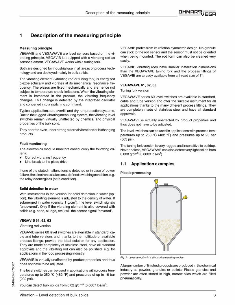
1.1 Application examplesPlastic processing
Fig. 1: Level detection in a silo storing plastic granules
A large number of finished productsare produced in the chemicalindustry as powder, granules or pellets. Plastic granules andpowder are often stored in high, narrow silos which are filledpneumatically.
Description of the measuring principle
Vibration – Level detection of bulk solids 3
3149
2-EN-
0703
07
Vibrating level switches like VEGAVIB / VEGAWAVE have pro-ven their worth for level detection of plastics. Even with smallestbulk densities of only 20 g/l and changing products, the instru-ments always deliver accurate results.Advantages:l Tuning forkapplicabledowntoadensity<20g/l (e.g.Aerosils)l Product-independent switching pointl Setup without filling
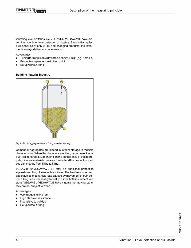
Buildingmaterial industry
Fig. 2: Silo for aggregate in the building materials industry
Cement or aggregates are placed in interim storage in multiplechamber silos.When the chambers are filled, large quantities ofdust are generated. Depending on the consistency of the aggre-gate, differentmaterial cones are formedand the product proper-ties can change from filling to filling.VEGAVIB 62/VEGAWAVE 62 offer an additional protectionagainst overfilling of silos with additives. The flexible suspensioncable avoids mechanical load caused by movement of bulk sol-ids. Filling is not necessary for setup. Since both instrument ver-sions VEGAVIB / VEGAWAVE have virtually no moving parts,they are not subject to wear.Advantages:l very rugged tuning forkl High abrasion resistancel insensitive to buildupl Setup without filling
Description of the measuring principle
4 Vibration – Level detection of bulk solids
31492-EN-070307

2 Type overview
VEGAVIB 61 VEGAVIB 62 VEGAVIB 63
Preferred application: Solids Solids SolidsLength: - 0.3 … 80m (1 … 262 ft) 0.3 … 4m (1… 13 ft)Process fitting: Thread G1 A, G1½ A, flanges Thread G1 A, G1½ A, flanges Thread G1 A, G1½ A, flangesProcess temperature: -50… +150 °C (-58… +302 °F) -20… +80 °C (-4 … +176 °F) -50… +150 °C (-58… +302 °F)Process temperature withtemperature adapter:
-50… +250 °C (-58… +482 °F) - -50… +250 °C (-58… +482 °F)
Process pressure: -1 … 16 bar/-100… 1600 kPa(-14.5… 232 psi)
-1 … 6 bar/-100… 600 kPa(-14.5… 87 psi)
-1 … 16 bar/-100… 1600 kPa(-14.5… 232 psi)
Signal output: relay output, transistor output,contactless electronic switch, two-wire output
relay output, transistor output,contactless electronic switch, two-wire output
relay output, transistor output,contactless electronic switch, two-wireoutput
Ruggedness: + + +Sensitivity: + + +Buildup: + + +Cleanability: ++ ++ ++Installation length: ++ ++ ++Orientation duringinstallation:
++ ++ ++
Sticking solids: ++ ++ ++
Type overview
Vibration – Level detection of bulk solids 5
3149
2-EN-
0703
07

VEGAWAVE 61 VEGAWAVE 62 VEGAWAVE 63
Preferred application: Solids Solids SolidsLength: - 0.3 … 80m (1 … 262 ft) 0.3 … 4m (1… 13 ft)Process fitting: threadG1½ A, flanges threadG1½ A, flanges threadG1½ A, flangesProcess temperature: -50… +150 °C (-58… +302 °F) -20… +80 °C (-4 … +176 °F) -50… +150 °C (-58… +302 °F)Process temperature withtemperature adapter:
-50… +250 °C (-58… +482 °F) - -50… +250 °C (-58… +482 °F)
Process pressure: -1 … 16 bar/-100… 1600 kPa(-14.5… 232 psi)
-1 … 6 bar/-100… 600 kPa(-14.5… 87 psi)
-1 … 16 bar/-100… 1600 kPa(-14.5… 232 psi)
Signal output: relay output, transistor output,contactless electronic switch, two-wire output
relay output, transistor output,contactless electronic switch, two-wire output
relay output, transistor output,contactless electronic switch, two-wireoutput
Ruggedness: ++ ++ ++Sensitivity: ++ ++ ++Buildup: ++ ++ ++Cleanability: - - -Installation length: + + +Orientation duringinstallation:
- - -
Sticking solids: - - -
Type overview
6 Vibration – Level detection of bulk solids
31492-EN-070307

Housing
Plastic Stainless steel Aluminium Aluminium (doublechamber)
Electronics
Relay output Transistor output Contactless elec-tronic switch
Two-wire output
Sensors
Vibrating rod Tuning fork
Approvals
Gas explosion pro-tection
Dust explosion pro-tection
Type overview
Vibration – Level detection of bulk solids 7
3149
2-EN-
0703
07
3 Mounting instructions
Switching pointIn general,VEGAVIB / VEGAWAVE can bemounted in any posi-tion. The instrument must be mounted in such a way that thevibratingelement is at the heightof the requestedswitchingpoint.The only exception is the mounting of the tuning fork verticallyfrom the bottom. In this position it can happen that product sticksbetween the fork tines.SocketThe vibrating element should protrude into the vessel to avoidbuildup.For that reason, avoidusingmountingbosses for flangesandscrewed fittings.This applies particularly for horizontal instal-lation and with adhesive products.Filling openingInstall the instrument in such a way that the vibrating elementdoes not protrude directly into the filling stream. Should such aninstallation location be necessary,mount a suitable baffle aboveor in front of the vibrating element, e.g. L80x8DIN 1028 (see Fig.Part "a."). In abrasive solids, mounting according to fig. Part "b."has proven to be a good solution. The mound that forms in theconcave baffle protects it from abrasion.
20°
a. b.
Fig. 3: Horizontal mountinga. Convex mountingb. Concave mounting
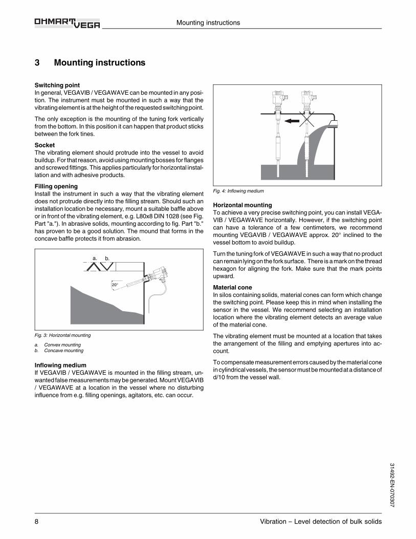
Inflowing mediumIf VEGAVIB / VEGAWAVE is mounted in the filling stream, un-wanted falsemeasurementsmaybegenerated.MountVEGAVIB/ VEGAWAVE at a location in the vessel where no disturbinginfluence from e.g. filling openings, agitators, etc. can occur.
Fig. 4: Inflowing medium
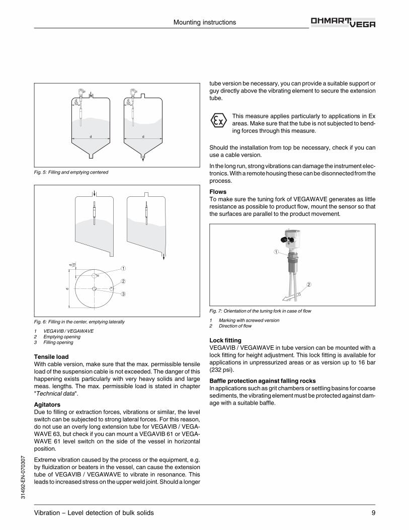
HorizontalmountingTo achieve a very precise switching point, you can install VEGA-VIB / VEGAWAVE horizontally. However, if the switching pointcan have a tolerance of a few centimeters, we recommendmounting VEGAVIB / VEGAWAVE approx. 20° inclined to thevessel bottom to avoid buildup.Turn the tuning fork ofVEGAWAVE in such away that no productcan remain lyingon the forksurface. There is amarkon the threadhexagon for aligning the fork. Make sure that the mark pointsupward.Material coneIn silos containing solids,material cones can form which changethe switching point. Please keep this in mind when installing thesensor in the vessel. We recommend selecting an installationlocation where the vibrating element detects an average valueof the material cone.The vibrating element must be mounted at a location that takesthe arrangement of the filling and emptying apertures into ac-count.Tocompensatemeasurementerrorscausedby thematerialconeincylindricalvessels, thesensormustbemountedatadistanceofd/10 from the vessel wall.
Mounting instructions
8 Vibration – Level detection of bulk solids
31492-EN-070307
d d
d10
d10
Fig. 5: Filling and emptying centered
dd 10 1
2
3
Fig. 6: Filling in the center, emptying laterally1 VEGAVIB / VEGAWAVE2 Emptying opening3 Filling opening
Tensile loadWith cable version, make sure that the max. permissible tensileload of the suspension cable is not exceeded. The danger of thishappening exists particularly with very heavy solids and largemeas. lengths. The max. permissible load is stated in chapter"Technical data".AgitatorsDue to filling or extraction forces, vibrations or similar, the levelswitch can be subjected to strong lateral forces. For this reason,do not use an overly long extension tube for VEGAVIB / VEGA-WAVE 63, but check if you can mount a VEGAVIB 61 or VEGA-WAVE 61 level switch on the side of the vessel in horizontalposition.Extreme vibration caused by the process or the equipment, e.g.by fluidization or beaters in the vessel, can cause the extensiontube of VEGAVIB / VEGAWAVE to vibrate in resonance. Thisleads to increasedstress on the upperweld joint.Shoulda longer
tube version be necessary, you can provide a suitable support orguy directly above the vibrating element to secure the extensiontube.
This measure applies particularly to applications in Exareas.Make sure that the tube is not subjected to bend-ing forces through this measure.
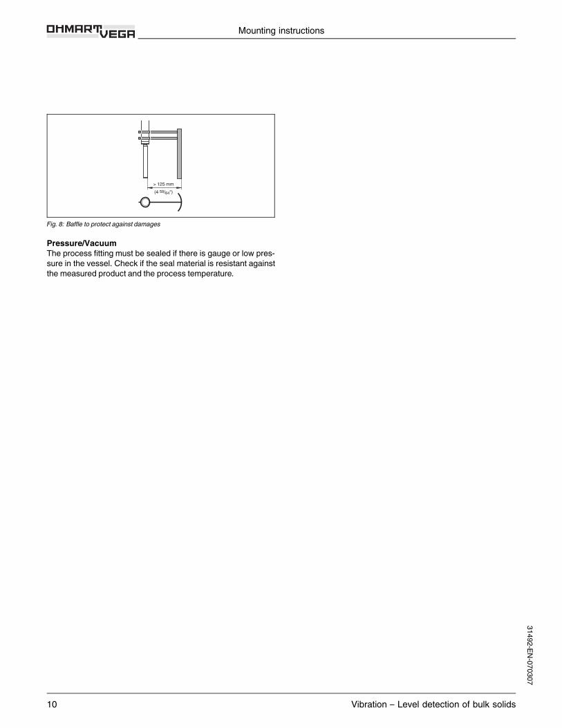
Should the installation from top be necessary, check if you canuse a cable version.In the long run, strongvibrations candamage the instrument elec-tronics.With a remotehousing thesecanbedisonnectedfrom theprocess.FlowsTo make sure the tuning fork of VEGAWAVE generates as littleresistance as possible to product flow,mount the sensor so thatthe surfaces are parallel to the product movement.
1
2
Fig. 7: Orientation of the tuning fork in case of flow1 Marking with screwed version2 Direction of flow
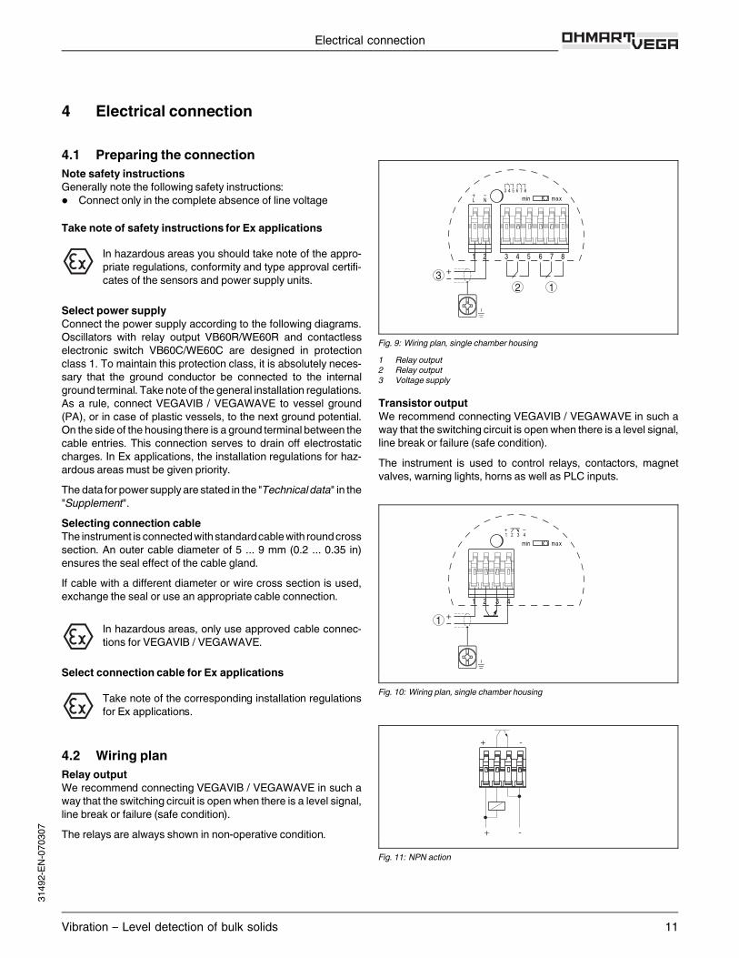
Lock fittingVEGAVIB / VEGAWAVE in tube version can be mounted with alock fitting for height adjustment. This lock fitting is available forapplications in unpressurized areas or as version up to 16 bar(232 psi).Baffle protection against falling rocksIn applications suchas grit chambers or settlingbasins for coarsesediments, the vibratingelementmust be protectedagainst dam-age with a suitable baffle.
Mounting instructions
Vibration – Level detection of bulk solids 9
3149
2-EN-
0703
07
> 125 mm(4 59/64")
Fig. 8: Baffle to protect against damages
Pressure/VacuumThe process fitting must be sealed if there is gauge or low pres-sure in the vessel. Check if the seal material is resistant againstthe measured product and the process temperature.
Mounting instructions
10 Vibration – Level detection of bulk solids
31492-EN-070307
4 Electrical connection
4.1 Preparing the connectionNote safety instructionsGenerally note the following safety instructions:l Connect only in the complete absence of line voltage
Take note of safety instructions for Ex applications
In hazardous areas you should take note of the appro-priate regulations, conformity and type approval certifi-cates of the sensors and power supply units.
Select power supplyConnect the power supply according to the following diagrams.Oscillators with relay output VB60R/WE60R and contactlesselectronic switch VB60C/WE60C are designed in protectionclass 1. To maintain this protection class, it is absolutely neces-sary that the ground conductor be connected to the internalground terminal. Take note of the general installation regulations.As a rule, connect VEGAVIB / VEGAWAVE to vessel ground(PA), or in case of plastic vessels, to the next ground potential.On the side of the housing there is a ground terminal between thecable entries. This connection serves to drain off electrostaticcharges. In Ex applications, the installation regulations for haz-ardous areas must be given priority.Thedata for power supply are stated in the "Technicaldata" in the"Supplement".Selecting connection cableThe instrument is connectedwithstandardcablewith roundcrosssection. An outer cable diameter of 5 ... 9 mm (0.2 ... 0.35 in)ensures the seal effect of the cable gland.If cable with a different diameter or wire cross section is used,exchange the seal or use an appropriate cable connection.
In hazardous areas, only use approved cable connec-tions for VEGAVIB / VEGAWAVE.
Select connection cable for Ex applications
Take note of the corresponding installation regulationsfor Ex applications.
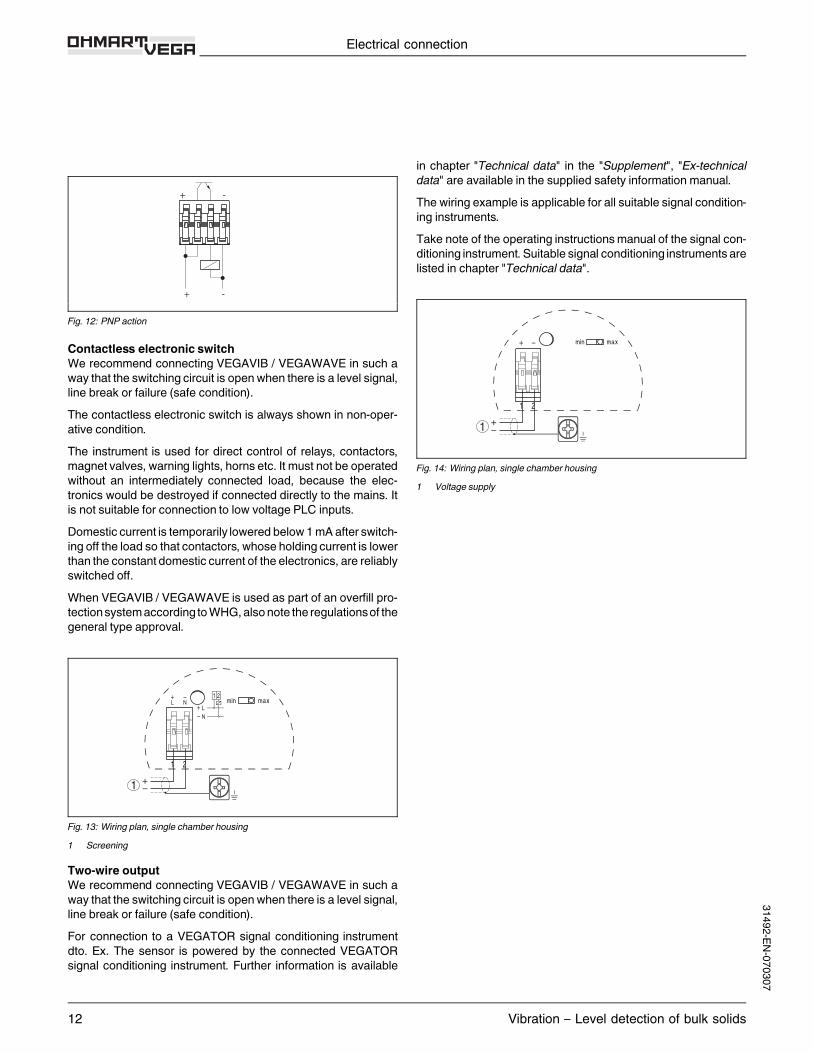
4.2 Wiring planRelay outputWe recommend connecting VEGAVIB / VEGAWAVE in such away that the switching circuit is open when there is a level signal,line break or failure (safe condition).The relays are always shown in non-operative condition.
32 1
Fig. 9: Wiring plan, single chamber housing1 Relay output2 Relay output3 Voltage supply
Transistor outputWe recommend connecting VEGAVIB / VEGAWAVE in such away that the switching circuit is open when there is a level signal,line break or failure (safe condition).The instrument is used to control relays, contactors, magnetvalves, warning lights, horns as well as PLC inputs.
1
Fig. 10: Wiring plan, single chamber housing
+ -
+ -
Fig. 11: NPN action
Electrical connection
Vibration – Level detection of bulk solids 11
3149
2-EN-
0703
07
+ -
+ -
Fig. 12: PNP action
Contactless electronic switchWe recommend connecting VEGAVIB / VEGAWAVE in such away that the switching circuit is open when there is a level signal,line break or failure (safe condition).The contactless electronic switch is always shown in non-oper-ative condition.The instrument is used for direct control of relays, contactors,magnet valves,warning lights, horns etc. It must not be operatedwithout an intermediately connected load, because the elec-tronics would be destroyed if connected directly to the mains. Itis not suitable for connection to low voltage PLC inputs.Domestic current is temporarily lowered below 1mA after switch-ing off the load so that contactors,whose holding current is lowerthan the constant domestic current of the electronics, are reliablyswitched off.When VEGAVIB / VEGAWAVE is used as part of an overfill pro-tectionsystemaccording toWHG,alsonote the regulationsof thegeneral type approval.
1
Fig. 13: Wiring plan, single chamber housing1 Screening
Two-wire outputWe recommend connecting VEGAVIB / VEGAWAVE in such away that the switching circuit is open when there is a level signal,line break or failure (safe condition).For connection to a VEGATOR signal conditioning instrumentdto. Ex. The sensor is powered by the connected VEGATORsignal conditioning instrument. Further information is available
in chapter "Technical data" in the "Supplement", "Ex-technicaldata" are available in the supplied safety information manual.The wiring example is applicable for all suitable signal condition-ing instruments.Take note of the operating instructionsmanual of the signal con-ditioning instrument.Suitable signal conditioning instruments arelisted in chapter "Technical data".
1
Fig. 14: Wiring plan, single chamber housing1 Voltage supply
Electrical connection
12 Vibration – Level detection of bulk solids
31492-EN-070307
5 Operation
5.1 Adjustment, general
3
4
5
1
2
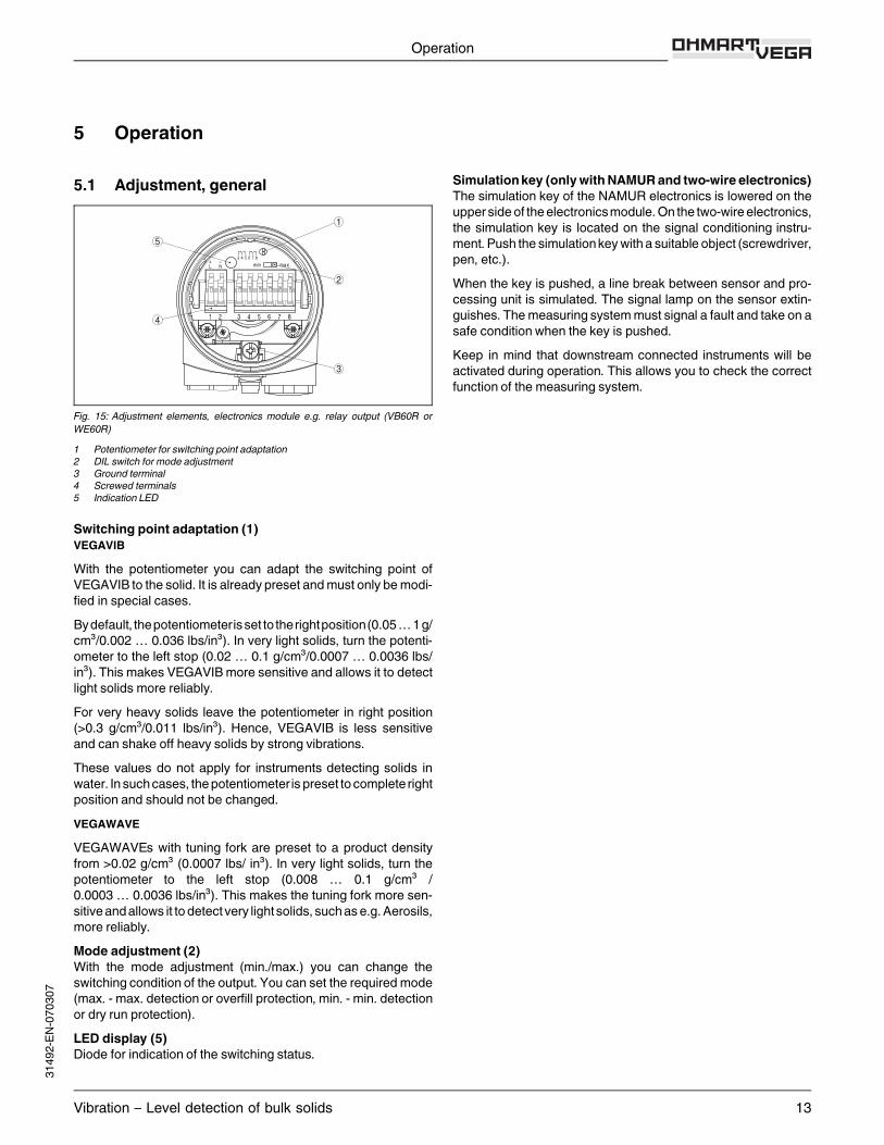
Fig. 15: Adjustment elements, electronics module e.g. relay output (VB60R orWE60R)1 Potentiometer for switching point adaptation2 DIL switch for mode adjustment3 Ground terminal4 Screwed terminals5 Indication LED
Switching point adaptation (1)VEGAVIBWith the potentiometer you can adapt the switching point ofVEGAVIB to the solid. It is already preset andmust only bemodi-fied in special cases.Bydefault, thepotentiometerisset to therightposition(0.05…1g/cm³/0.002 … 0.036 lbs/in³). In very light solids, turn the potenti-ometer to the left stop (0.02 … 0.1 g/cm³/0.0007 … 0.0036 lbs/in³). This makes VEGAVIBmore sensitive and allows it to detectlight solids more reliably.For very heavy solids leave the potentiometer in right position(>0.3 g/cm³/0.011 lbs/in³). Hence, VEGAVIB is less sensitiveand can shake off heavy solids by strong vibrations.These values do not apply for instruments detecting solids inwater. Insuchcases, thepotentiometer is preset to complete rightposition and should not be changed.VEGAWAVEVEGAWAVEs with tuning fork are preset to a product densityfrom >0.02 g/cm³ (0.0007 lbs/ in³). In very light solids, turn thepotentiometer to the left stop (0.008 … 0.1 g/cm³ /0.0003 … 0.0036 lbs/in³). This makes the tuning fork more sen-sitiveandallows it to detect very light solids, suchase.g.Aerosils,more reliably.Mode adjustment (2)With the mode adjustment (min./max.) you can change theswitching condition of the output. You can set the required mode(max. -max. detection or overfill protection,min. -min. detectionor dry run protection).LED display (5)Diode for indication of the switching status.
Simulationkey (onlywithNAMUR and two-wire electronics)The simulation key of the NAMUR electronics is lowered on theupper sideof theelectronicsmodule.On the two-wireelectronics,the simulation key is located on the signal conditioning instru-ment.Push the simulationkeywith a suitable object (screwdriver,pen, etc.).When the key is pushed, a line break between sensor and pro-cessing unit is simulated. The signal lamp on the sensor extin-guishes. Themeasuring systemmust signal a fault and take on asafe condition when the key is pushed.Keep in mind that downstream connected instruments will beactivated during operation. This allows you to check the correctfunction of the measuring system.
Operation
Vibration – Level detection of bulk solids 13
3149
2-EN-
0703
07
6 Technical data
General dataMaterial 316L corresponds to 1.4404 or 1.4435VEGAVIB 61/VEGAWAVE 61Materials, wetted parts- Process fitting - thread 316L- Process fitting - flange 316L- Seal Klingersil C-4400- Vibrating element - VEGAVIB 316L/318S13 (1.4462)- Vibrating element - VEGAWAVE 316L- Extension tube (VEGAVIB 61) ø 29mm (1.14 in) 316L- Extension tube (VEGAWAVE 61) ø 43mm (1.7 in) 316LMaterials, non-wetted parts- Housing Plastic PBT (Polyester), Alu die-casting powder-coated, 316L- Seal ring between housing and housing cover NBR (stainless steel housing), silicone (Alu/plastic housing)- Ground terminal 316Ti/316LWeights- VEGAVIB 61 with plastic housing 1150 g (40 oz)- VEGAVIB 61 with Aluminium housing 1600 g (56 oz)- VEGAVIB 61 with stainless steel housing 1950 g (69 oz)- VEGAWAVE 61 with plastic housing 1500 g (53 oz)- VEGAWAVE 61 with Aluminium housing 1950 g (69 oz)- VEGAWAVE 61 with stainless steel housing 2300 g (81 oz)Max. lateral load 600 N (135 lbf)VEGAVIB 62/VEGAWAVE 62Materials, wetted parts- Process fitting - thread 316L- Process fitting - flange 316L- Seal CR, CSM- Vibrating element - VEGAVIB 316L/318S13 (1.4462)- Vibrating element - VEGAWAVE 316L- Suspension cable PURMaterials, non-wetted parts- Housing Plastic PBT (Polyester), Alu die-casting powder-coated, 316L- Seal ring between housing and housing cover NBR (stainless steel housing), silicone (Alu/plastic housing)- Ground terminal 316Ti/316LWeights- VEGAVIB 62 with plastic housing 1150 g (40 oz)- VEGAVIB 62 with Aluminium housing 1600 g (56 oz)- VEGAVIB 62 with stainless steel housing 1950 g (69 oz)- VEGAWAVE 62 with plastic housing 1500 g (53 oz)- VEGAWAVE 62 with Aluminium housing 1950 g (69 oz)- VEGAWAVE 62 with stainless steel housing 2300 g (81 oz)- Suspension cable ca. 165 g/m (1.8 oz/ft)Max. permissible tensile load 3000 N (675 lbs)Sensor length 0.48 … 80 m (1.6… 262 ft)VEGAVIB 63/VEGAWAVE 63Materials, wetted parts- Process fitting - thread 316L- Process fitting - flange 316L- Seal Klingersil C-4400- Vibrating element - VEGAVIB 316L/318S13 (1.4462)- Vibrating element - VEGAWAVE 316L- Extension tube (VEGAVIB 63) ø 29mm (1.14 in) 316L- Extension tube (VEGAWAVE 63) ø 43mm (1.7 in) 316LMaterials, non-wetted parts- Housing Plastic PBT (Polyester), Alu die-casting powder-coated, 316L- Seal ring between housing and housing cover NBR (stainless steel housing), silicone (Alu/plastic housing)- Ground terminal 316Ti/316L
Technical data
14 Vibration – Level detection of bulk solids
31492-EN-070307
Weights- VEGAVIB 63 with plastic housing 1150 g (40 oz)- VEGAVIB 63 with Aluminium housing 1600 g (56 oz)- VEGAVIB 63 with stainless steel housing 1950 g (69 oz)- VEGAWAVE 63 with plastic housing 1500 g (53 oz)- VEGAWAVE 63 with Aluminium housing 1950 g (69 oz)- VEGAWAVE 63 with stainless steel housing 2300 g (81 oz)- Extension tube (VEGAVIB 63) ø 29mm (1.14 in) approx. 1450 g/m (15.6 oz/ft)- Extension tube (VEGAWAVE 63) ø 43mm (1.7 in) approx. 2000 g/m (21.5 oz/ft)Sensor length 0.3 … 4m (1… 13 ft)Max. lateral load- VEGAVIB 63 140 Nm (103 lbf ft),max. 400 N (90 lbf)- VEGAWAVE 63 290 Nm (214 lbf ft),max. 600 N (135 lbf)
Output variableRelay outputOutput Relay output (DPDT), 2 floating spdtsTurn-on voltage- min. 10mV- max. 253 V AC, 253 V DCSwitching current- min. 10 µA- max. 5 A AC, 1 A DCBreaking capacity- max. 1250 VA, 50WContact material (relay contacts) AgCdO and Au platedModes (adjustable) min./max.Delay time- when immersed approx. 0.5 s- when laid bare ca. 1 sTransistor outputOutput floating transistor output, overload and permanently shortcircuit proofLoad current max. 400mATurn-on voltage max. 55 V DCBlocking current <100 µAModes (adjustable) min./max.Delay time- when immersed approx. 0.5 s- when laid bare approx. 1 sContactless electronic switchOutput Contactless electronic switchModes (adjustable) min./max.Delay time- when immersed approx. 0.5 s- when laid bare ca. 1 sTwo-wire outputOutput Two-wire outputSuitable signal conditioning instruments VEGATOR 536Ex, 537Ex, 636ExOutput signal- Mode min. Vibrating element uncovered: 16mA ±1 mA, vibrating element covered:
8mA ±1 mA- Mode max. Vibrating element uncovered: 8mA ±1 mA, vibrating element covered:
16mA ±1 mA- Failure message <2mAModes (adjustable) min./max.
Technical data
Vibration – Level detection of bulk solids 15
3149
2-EN-
0703
07
Delay time- when immersed approx. 0.5 s- when laid bare ca. 1 sNAMUR outputOutput Two-wire NAMUR outputCurrent consumption- Falling characteristics (max.) ≥2.2 mA uncovered/≤1 mA covered- Rising characteristics (min.) ≤1mA uncovered/≥2.2 mA covered- Failure message ≤1mANecessary processing system NAMUR processing system according to IEC 60947-5-6 (EN 50227/
DIN 19234)Modes (NAMUR output adjustable to falling or rising characteristics)- min. rising characteristic curve (High current when immersed)- max. falling characteristics (Low current when immersed)
Ambient conditionsAmbient temperature on the housing -40… +70 °C (-40… +158 °F)Storage and transport temperature -40… +80 °C (-40… +176 °F)
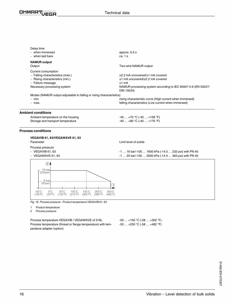
Process conditionsVEGAVIB 61, 63/VEGAWAVE 61, 63Parameter Limit level of solidsProcess pressure- VEGAVIB 61, 63 -1 … 16 bar/-100… 1600 kPa (-14.5… 232 psi) with PN 40- VEGAWAVE 61, 63 -1 … 25 bar/-100… 2500 kPa (-14.5… 363 psi) with PN 40
6 bar(87psi)
-50˚C(-58˚F)
16 bar(232psi)
50˚C(122˚F)
100˚C(212˚F)
0˚C(32˚F)
150˚C(302˚F)
200˚C(392˚F)
250˚C(482˚F)
1
2
Fig. 16: Process pressure - Product temperature VEGAVIB 61, 631 Product temperature2 Process pressure
Process temperature VEGAVIB / VEGAWAVE of 316L -50… +150 °C (-58… +302 °F)Process temperature (thread or flange temperature) with tem-perature adapter (option)
-50… +250 °C (-58… +482 °F)
Technical data
16 Vibration – Level detection of bulk solids
31492-EN-070307

1
23
-50˚C(-58˚F)
50˚C(122˚F)
40˚C(104˚F)
-40˚C(-40˚F)
80˚C(176˚F)
0˚C(32˚F)
100˚C(212˚F)
150˚C(302˚F)
200˚C(392˚F)
250˚C(482˚F)
Fig. 17: Ambient temperature - Product temperature1 Product temperature2 Ambient temperature3 Temperature range with temperature adapter
Product density- VEGAVIB 61, 63 >0.02 g/cm³ (0.0007 lbs/in³)- VEGAWAVE 61, 63 >0.008 g/cm³ (0.0003 lbs/in³)Granular size- VEGAVIB 61, 63 max. ø 10mm (0.4 in)- VEGAWAVE 61, 63 max. ø 15mm (0.6 in)VEGAVIB 62/VEGAWAVE 62Parameter Limit level of solidsProcess pressure -1 … 6 bar/-100… 600 kPa (-14.5 … 87 psi) with PN 40Process temperature VEGAVIB 62, VEGAWAVE 62 of 316L -20… +80 °C (-4 … +176 °F)Product density- VEGAVIB 62 >0.02 g/cm³ (0.0007 lbs/in³)- VEGAWAVE 62 >0.008 g/cm³ (0.0003 lbs/in³)Granular size- VEGAVIB 62 max. ø 10mm (0.4 in)- VEGAWAVE 62 max. ø 15mm (0.6 in)
Electromechanical dataCable entry/plug (dependent on the version)- Single chamber housing l 1x cable entryM20x1.5 (cable-ø 5 … 9 mm), 1x blind stopper
M20x1.5; attached 1x cable entryM20x1.5or:l 1x cable entry½NPT, 1x blind stopper½NPT, 1x cable entry½NPTor:l 1x plugM12x1, 1x blind stopperM20x1.5
Spring-loaded terminals for wire cross-section up to 1.5mm²
Adjustment elementsElectronics versions - relay, transistor output, contactless electronic switchMode switch- min. Min. detection or dry run protection- max. Max. detection or overfill protection
Technical data
Vibration – Level detection of bulk solids 17
3149
2-EN-
0703
07
Electronics version - two-wire outputMode switch- min. Vibrating element uncovered: 16mA ±1 mA Vibrating element covered:
8mA ±1 mA- max. Vibrating element uncovered: 8mA ±1 mA Vibrating element covered:
16mA ±1 mAElectronics version - NAMUR outputMode switch- min. rising characteristic curve (High current when immersed)- max. falling characteristics (Low current when immersed)
Voltage supplyRelay outputSupply voltage 20… 253 V AC, 50/60 Hz, 20… 72 V DC (at U >60 V DC, the ambient
temperature can be max. 50 °C/122 °F)Power consumption 1… 8 VA (AC), approx. 1.3W (DC)Transistor outputSupply voltage 10… 55 V DCPower consumption max. 0.5WContactless electronic switchSupply voltage 20… 253 V AC, 50/60 Hz, 20… 253 V DCDomestic current requirement approx. 3 mA (via load circuit)Load current- min. 10mA- max. 400mA (at I >300mA the ambient temperature can bemax. 60 °C/140 °F)
max. 4 A up to 40msTwo-wire outputSupply voltage 10… 36 V DC (via the VEGA signal conditioning instrument)
NAMUR outputSupply voltage (standard characteristics) for connection to an amplifier according to NAMUR IEC 60947-5-6, ap-
prox. 8.2 VOpen-circuit voltage U0 approx. 8.2 VShortcircuit current IU approx. 8.2 mA
Electrical protective measuresElectronics versions - relay output, contactless electronic switchProtection IP 66/IP 67Overvoltage category IIIProtection class IElectronics versions - Transistor, two-wire, NAMUR outputProtection IP 66/IP 67Overvoltage category IIIProtection class II
Technical data
18 Vibration – Level detection of bulk solids
31492-EN-070307

Approvals - VEGAVIBVEGAVIB 61, 63 - electronics versions - relay output, transistor output, contactless electronic switchATEX ATEX II 1/2G, 2G EEx d IIC T1… T6
ATEX II 1D, 1/2D, 2D IP66TATEX II 1D, 1/2D, 2D IP66T + ATEX II 1/2G, 2G EEx d IIC T1 … T6
FM FM (NI) CL I, DIV 2, GP ABCD; (DIP) CL II, III, DIV 1, GP EFG
FM (XP) CL I, DIV 1, GP ABCD; (DIP) CL II, III, DIV 1, GP EFGCSA CSA (NI) CL I, DIV 2, GP ABCD; (DIP) CL II, III, DIV 1, GP EFG
CSA (XP) CL I, DIV 1, GP ABCD; (DIP) CL II, III, DIV 1, GP EFGIEC Ex tD A20/21, A21 IP66TVEGAVIB 61, 63 - electronics version - two-wire output, NAMUR outputATEX ATEX II 1G, 1/2G, 2G EEx ia IIC T6
ATEX II 1/2G, 2G EEx d IIC T1… T6ATEX II 1D, 1/2D, 2D IP66TATEX II 1D, 1/2D, 2D IP66T + ATEX II 1G, 1/2G, 2GEEx ia IIC T6ATEX II 1D, 1/2D, 2D IP66T + ATEX II 1/2G, 2G EEx d IIC T1 … T6
FM (nur Zweileiterausführung) FM (IS) CL I, II, III DIV 1, GP ABCDEFGFM (NI) CL I, DIV 2, GP ABCD; (DIP) CL II, III, DIV 1, GP EFG
FM (XP) CL I, DIV 1, GP ABCD; (DIP) CL II, III, DIV 1, GP EFGCSA (nur Zweileiterausführung) CSA (IS) CL I, II, III DIV 1, GP ABCDEFG
CSA (XP) CL I, DIV 1, GP ABCD; (DIP) CL II, III, DIV 1, GP EFGIEC Ex tD A20/21, A21 IP66TVEGAVIB 62 - electronics versions - relay output, transistor output, contactless electronic switchATEX ATEX II 1D, 1/2D, 2D IP66TFM FM (NI) CL I, DIV 2, GP ABCD; (DIP) CL II, III, DIV 1, GP EFGCSA CSA (NI) CL I, DIV 2, GP ABCD; (DIP) CL II, III, DIV 1, GP EFGIEC Ex tD A20/21, A21 IP66TVEGAVIB 62 - electronics version - two-wire output, NAMUR outputATEX ATEX II 1G, 1/2G, 2G EEx ia IIC T6
ATEX II 1D, 1/2D, 2D IP66TATEX II 1D, 1/2D, 2D IP66T + ATEX II 1G, 1/2G, 2G EEx ia IIC T6
IEC Ex tD A20/21, A21 IP66TFM (nur Zweileiterausführung) FM (IS) CL I, II, III DIV 1, GP ABCDEFG
FM (NI) CL I, DIV 2, GP ABCD; (DIP) CL II, III, DIV 1, GP EFGCSA (nur Zweileiterausführung) CSA (IS) CL I, II, III DIV 1, GP ABCDEFGIEC Ex tD A20/21, A21 IP66T
CE conformityElectronics versions - Relay, transistor, two-wire, NAMUR outputEMVG (89/336/EWG), Emission: EN 61326: 1997 (class B),Susceptibility: EN 61326: 1997/A1: 1998NSR (73/23/EWG), EN 61010-1: 2001Electronics version - contactless electronic switchEMVG (89/336/EWG), Emission: EN 61326/A1: 1998 (classB), Susceptibility: EN 61326: 1997/A1: 1998NSR (73/23/EWG), EN 61010-1: 2001
Technical data
Vibration – Level detection of bulk solids 19
3149
2-EN-
0703
07
7 Dimensions
Housing
ø 77~ 69
117
(*1
28)
20x1,5
~ 116
116
(*1
25)
~ 87 (96)
ø 84
120
(*1
29)
~ 69
112
(*12
3)
½ ½ ½ NPT
M20x1,5/½ NPT
M16x1,5
1 2 3 4
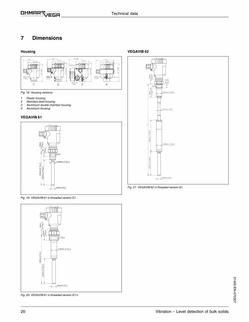
Fig. 18: Housing versions1 Plastic housing2 Stainless steel housing3 Aluminium double chamber housing4 Aluminium housing
VEGAVIB 61
25m
m(6
3 /64
")20
(25 /
32)
161m
m (
6 11
/ 32"
)
125m
m (
4 59
/ 64"
)
ø16mm (5/8")
ø 29mm (1 9/64")
G1A
Fig. 19: VEGAVIB 61 in threaded versionG1
33m
m(1
19 /
64")
22m
m(5
5 /64
")
125m
m (
4 59
/ 64"
)
238m
m (
9 3 /
8")
ø16mm (5/8")
G1½A
ø 29mm (1 9/64")
Fig. 20: VEGAVIB 61 in threaded versionG1½
VEGAVIB 62
49m
m(1
59/
64")
25m
m(6
3/64
")
20m
m(2
5/32
")
L
185m
m (
7 9/
32")
125m
m (
4 59
/64"
)
ø16mm (5/8")
G1A
ø 29mm (1 9/64")
ø 29mm (1 9/64")
ø 11mm ( 7/16")
Fig. 21: VEGAVIB 62 in threaded versionG1
Technical data
20 Vibration – Level detection of bulk solids
31492-EN-070307
22m
m(5
5 /64
")54
mm
(2 1
/ 8")
L
185m
m (
7 9 /
32")
125m
m (
4 59
/ 64"
)
ø16mm (5/8")
G1½A
ø 29mm (1 9/64")
ø 29mm (1 9/64")
ø 11mm ( 7/16")
Fig. 22: VEGAVIB 62 in threaded versionG1½
VEGAVIB 63
20m
m(2
5 /32
")
25m
m(6
3 /64
")
L
125m
m (
4 59
/ 64"
)
ø16mm (5/8")
G1A
ø 29mm (1 9/64")
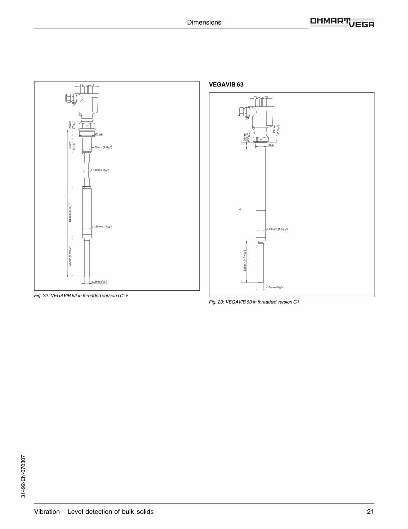
Fig. 23: VEGAVIB 63 in threaded versionG1
Dimensions
Vibration – Level detection of bulk solids 21
3149
2-EN-
0703
07

22m
m(5
5 /64
")
33m
m(1
19 /
64")
L
125m
m (
4 59
/ 64"
)
ø16mm (5/8")
G1½A
ø 29mm (1 9/64")
Fig. 24: VEGAVIB 63 in threaded versionG1½
VEGAWAVE 61
22m
m(5
5 /64
")
33m
m(1
19 /
64")
220m
m (
8 21
/ 32"
)
150m
m (
5 29
/ 32"
)
G1½A
ø 43mm (1 11/16")
Fig. 25: VEGAWAVE 61 in threaded versionG1½
VEGAWAVE 62
150m
m (5
29/ 32
")L
22mm
(55/ 64
")40
mm(1
37/ 64
")
33mm
(1 19
/ 64")
G1½Aø 43mm (1 11/16")
ø 11mm (7/16")
ø 43mm (1 11/16")
160m
m (6
19/ 64
")
Fig. 26: VEGAWAVE 62 in threaded versionG1½
Dimensions
22 Vibration – Level detection of bulk solids
31492-EN-070307
VEGAWAVE 6322
mm
(55 /
64")
33m
m(1
19 /
64")
G1½A
150m
m (
5 29
/ 32"
)
L
ø 43mm (1 11/16")
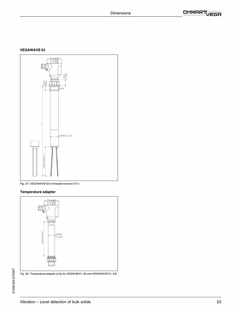
Fig. 27: VEGAWAVE 63 in threaded versionG1½
Temperature adapter
ø 34 mm(1 11/32")
178 m
m (7
1 /64
")
Fig. 28: Temperature adapter (only for VEGAVIB 61, 63 and VEGAWAVE 61, 63)
Dimensions
Vibration – Level detection of bulk solids 23
3149
2-EN-
0703
07
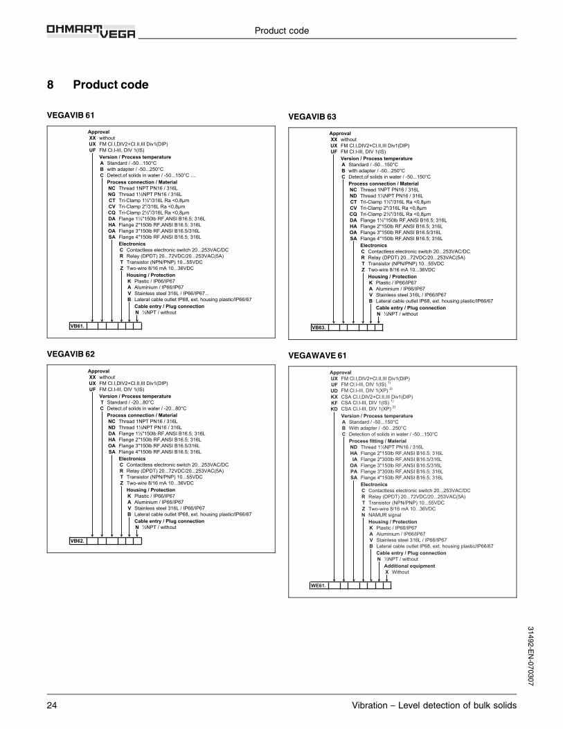
8 Product code
VEGAVIB 61ApprovalXX withoutUX FM Cl.I,DIV2+Cl.II,III Div1(DIP) UF FM Cl.I-III, DIV 1(IS)
Version / Process temperatureA Standard / -50...150°CB with adapter / -50...250°CC Detect.of solids in water / -50...150°C ....
Process connection / MaterialNC Thread 1NPT PN16 / 316LNG Thread 1½NPT PN16 / 316L CT Tri-Clamp 1½"/316L Ra <0,8µmCV Tri-Clamp 2"/316L Ra <0,8µm CQ Tri-Clamp 2½"/316L Ra <0,8µmDA Flange 1½"150lb RF,ANSI B16.5; 316L HA Flange 2"150lb RF,ANSI B16.5; 316LOA Flange 3"150lb RF,ANSI B16.5/316L SA Flange 4"150lb RF,ANSI B16.5; 316L
ElectronicsC Contactless electronic switch 20...253VAC/DCR Relay (DPDT) 20...72VDC/20...253VAC(5A) T Transistor (NPN/PNP) 10...55VDC Z Two-wire 8/16 mA 10...36VDC
Housing / ProtectionK Plastic / IP66/IP67 A Aluminium / IP66/IP67V Stainless steel 316L / IP66/IP67...B Lateral cable outlet IP68, ext. housing plastic/IP66/67
Cable entry / Plug connectionN ½NPT / without
VB61.
VEGAVIB 62ApprovalXX withoutUX FM Cl.I,DIV2+Cl.II,III Div1(DIP) UF FM Cl.I-III, DIV 1(IS)
Version / Process temperatureT Standard / -20...80°C C Detect.of solids in water / -20...80°C
Process connection / MaterialNC Thread 1NPT PN16 / 316LND Thread 1½NPT PN16 / 316L DA Flange 1½"150lb RF,ANSI B16.5; 316L HA Flange 2"150lb RF,ANSI B16.5; 316LOA Flange 3"150lb RF,ANSI B16.5/316L SA Flange 4"150lb RF,ANSI B16.5; 316L
ElectronicsC Contactless electronic switch 20...253VAC/DC R Relay (DPDT) 20...72VDC/20...253VAC(5A) T Transistor (NPN/PNP) 10...55VDC Z Two-wire 8/16 mA 10...36VDC
Housing / ProtectionK Plastic / IP66/IP67A Aluminium / IP66/IP67V Stainless steel 316L / IP66/IP67B Lateral cable outlet IP68, ext. housing plastic/IP66/67
Cable entry / Plug connectionN ½NPT / without
VB62.
VEGAVIB 63ApprovalXX withoutUX FM Cl.I,DIV2+Cl.II,III Div1(DIP) UF FM Cl.I-III, DIV 1(IS)
Version / Process temperatureA Standard / -50...150°CB with adapter / -50...250°CC Detect.of solids in water / -50...150°C
Process connection / MaterialNC Thread 1NPT PN16 / 316L ND Thread 1½NPT PN16 / 316L CT Tri-Clamp 1½"/316L Ra <0,8µmCV Tri-Clamp 2"/316L Ra <0,8µm CQ Tri-Clamp 2½"/316L Ra <0,8µmDA Flange 1½"150lb RF,ANSI B16.5; 316L HA Flange 2"150lb RF,ANSI B16.5; 316LOA Flange 3"150lb RF,ANSI B16.5/316L SA Flange 4"150lb RF,ANSI B16.5; 316L
ElectronicsC Contactless electronic switch 20...253VAC/DC R Relay (DPDT) 20...72VDC/20...253VAC(5A) T Transistor (NPN/PNP) 10...55VDC Z Two-wire 8/16 mA 10...36VDC
Housing / ProtectionK Plastic / IP66/IP67A Aluminium / IP66/IP67V Stainless steel 316L / IP66/IP67B Lateral cable outlet IP68, ext. housing plastic/IP66/67
Cable entry / Plug connectionN ½NPT / without
VB63.
VEGAWAVE 61ApprovalUX FM Cl.I,DIV2+Cl.II,III Div1(DIP)UF FM Cl.I-III, DIV 1(IS) 1)
UD FM Cl.I-III, DIV 1(XP) 2)
KX CSA Cl.I,DIV2+Cl.II,III Div1(DIP) KF CSA Cl.I-III, DIV 1(IS) 1)
KD CSA Cl.I-III, DIV 1(XP) 2)
Version / Process temperatureA Standard / -50...150°CB With adapter / -50...250°CC Detection of solids in water / -50...150°C
Process fitting / MaterialND Thread 1½NPT PN16 / 316LHA Flange 2"150lb RF,ANSI B16.5; 316LIA Flange 2"300lb RF,ANSI B16.5/316L
OA Flange 3"150lb RF,ANSI B16.5/316LPA Flange 3"300lb RF,ANSI B16.5; 316LSA Flange 4"150lb RF,ANSI B16.5; 316L
ElectronicsC Contactless electronic switch 20...253VAC/DCR Relay (DPDT) 20...72VDC/20...253VAC(5A)T Transistor (NPN/PNP) 10...55VDCZ Two-wire 8/16 mA 10...36VDC N NAMUR signal
Housing / ProtectionK Plastic / IP66/IP67 A Aluminium / IP66/IP67V Stainless steel 316L / IP66/IP67B Lateral cable outlet IP68, ext. housing plastic/IP66/67
Cable entry / Plug connectionN ½NPT / without
Additional equipmentX Without
WE61.
Product code
24 Vibration – Level detection of bulk solids
31492-EN-070307
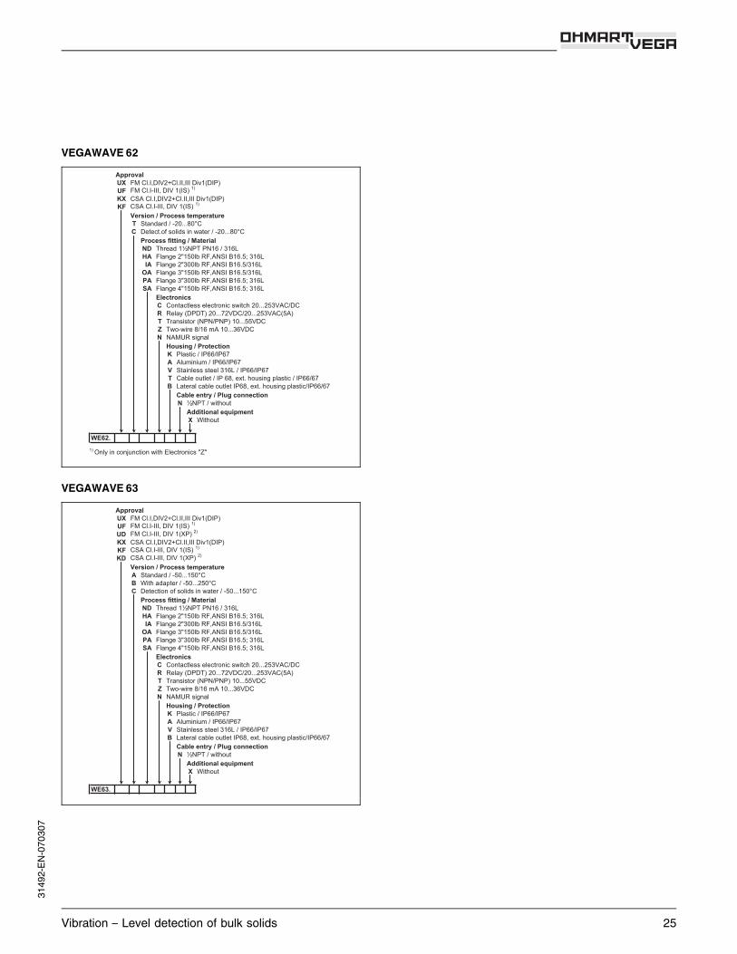
VEGAWAVE 62ApprovalUX FM Cl.I,DIV2+Cl.II,III Div1(DIP)UF FM Cl.I-III, DIV 1(IS) 1)
KX CSA Cl.I,DIV2+Cl.II,III Div1(DIP)KF CSA Cl.I-III, DIV 1(IS) 1)
Version / Process temperatureT Standard / -20...80°CC Detect.of solids in water / -20...80°C
Process fitting / MaterialND Thread 1½NPT PN16 / 316LHA Flange 2"150lb RF,ANSI B16.5; 316LIA Flange 2"300lb RF,ANSI B16.5/316L
OA Flange 3"150lb RF,ANSI B16.5/316L PA Flange 3"300lb RF,ANSI B16.5; 316LSA Flange 4"150lb RF,ANSI B16.5; 316L
ElectronicsC Contactless electronic switch 20...253VAC/DCR Relay (DPDT) 20...72VDC/20...253VAC(5A)T Transistor (NPN/PNP) 10...55VDCZ Two-wire 8/16 mA 10...36VDCN NAMUR signal
Housing / ProtectionK Plastic / IP66/IP67A Aluminium / IP66/IP67V Stainless steel 316L / IP66/IP67T Cable outlet / IP 68, ext. housing plastic / IP66/67B Lateral cable outlet IP68, ext. housing plastic/IP66/67
Cable entry / Plug connectionN ½NPT / without
Additional equipmentX Without
WE62.1) Only in conjunction with Electronics "Z"
VEGAWAVE 63ApprovalUX FM Cl.I,DIV2+Cl.II,III Div1(DIP)UF FM Cl.I-III, DIV 1(IS) 1)
UD FM Cl.I-III, DIV 1(XP) 2)
KX CSA Cl.I,DIV2+Cl.II,III Div1(DIP) KF CSA Cl.I-III, DIV 1(IS) 1)
KD CSA Cl.I-III, DIV 1(XP) 2)
Version / Process temperatureA Standard / -50...150°CB With adapter / -50...250°CC Detection of solids in water / -50...150°C
Process fitting / MaterialND Thread 1½NPT PN16 / 316LHA Flange 2"150lb RF,ANSI B16.5; 316L IA Flange 2"300lb RF,ANSI B16.5/316L
OA Flange 3"150lb RF,ANSI B16.5/316LPA Flange 3"300lb RF,ANSI B16.5; 316LSA Flange 4"150lb RF,ANSI B16.5; 316L
ElectronicsC Contactless electronic switch 20...253VAC/DC R Relay (DPDT) 20...72VDC/20...253VAC(5A)T Transistor (NPN/PNP) 10...55VDCZ Two-wire 8/16 mA 10...36VDCN NAMUR signal
Housing / ProtectionK Plastic / IP66/IP67A Aluminium / IP66/IP67V Stainless steel 316L / IP66/IP67B Lateral cable outlet IP68, ext. housing plastic/IP66/67
Cable entry / Plug connectionN ½NPT / without
Additional equipmentX Without
WE63.
Vibration – Level detection of bulk solids 25
3149
2-EN-
0703
07

26 Vibration – Level detection of bulk solids
31492-EN-070307
Vibration – Level detection of bulk solids 27
3149
2-EN-
0703
07
VEGA Grieshaber KGAm Hohenstein 11377761 SchiltachGermanyPhone +49 7836 50-0Fax +49 7836 50-201E-Mail: [email protected]
You can find at www.vega.comdownloads of the followingl operating instructions manualsl menu schematicsl softwarel certificatesl approvalsand much, much more
Subject to change without prior notice 31492-EN-070307