product information vegavib 61 - 63 / vegawave 61 - 63 · l tuning fork implementable down to a...
TRANSCRIPT

Level detection in bulk solids
Vibration
VEGAVIB 61 - 63
VEGAWAVE 61 - 63
Product Information
Contents
2 Vibration – Level detection in bulk solids
Contents
1 Description of the measuring principle . . . . . . . . . . . . . . . . . . . . . . . . . . . . . . . . . . . . . . . . . . . . . . . . . . . . . . . . . . . 3
2 Type overview . . . . . . . . . . . . . . . . . . . . . . . . . . . . . . . . . . . . . . . . . . . . . . . . . . . . . . . . . . . . . . . . . . . . . . . . . . . . . . 5
3 Mounting instructions . . . . . . . . . . . . . . . . . . . . . . . . . . . . . . . . . . . . . . . . . . . . . . . . . . . . . . . . . . . . . . . . . . . . . . . . 7
4 Electrical connection
4.1 Preparing the connection . . . . . . . . . . . . . . . . . . . . . . . . . . . . . . . . . . . . . . . . . . . . . . . . . . . . . . . . . . . . . . . . . 104.2 Wiring plan . . . . . . . . . . . . . . . . . . . . . . . . . . . . . . . . . . . . . . . . . . . . . . . . . . . . . . . . . . . . . . . . . . . . . . . . . . . 10
5 Operation
5.1 Adjustment, general . . . . . . . . . . . . . . . . . . . . . . . . . . . . . . . . . . . . . . . . . . . . . . . . . . . . . . . . . . . . . . . . . . . . . 125.2 Recurring function test - NAMUR electronics . . . . . . . . . . . . . . . . . . . . . . . . . . . . . . . . . . . . . . . . . . . . . . . . . . . 125.3 Recurring function test - Two-wire electronics . . . . . . . . . . . . . . . . . . . . . . . . . . . . . . . . . . . . . . . . . . . . . . . . . . . 13
6 Technical data . . . . . . . . . . . . . . . . . . . . . . . . . . . . . . . . . . . . . . . . . . . . . . . . . . . . . . . . . . . . . . . . . . . . . . . . . . . . . 14
7 Dimensions . . . . . . . . . . . . . . . . . . . . . . . . . . . . . . . . . . . . . . . . . . . . . . . . . . . . . . . . . . . . . . . . . . . . . . . . . . . . . . . 19
8 Product code . . . . . . . . . . . . . . . . . . . . . . . . . . . . . . . . . . . . . . . . . . . . . . . . . . . . . . . . . . . . . . . . . . . . . . . . . . . . . . 23
Take note of safety instructions for Ex applications
Please note theEx specific safety informationwhich you can find on our homepagewww.vega.com\services\downloads and
which comes with every instrument. In hazardous areas you should take note of the appropriate regulations, conformity and
type approval certificates of the sensors and power supply units. The sensors must only be operated on intrinsically safe
circuits. The permissible electrical values are stated in the certificate.
29438-EN-081119

1 Description of the measuring principle
Measuring principle
VEGAVIB andVEGAWAVE are point level sensors based on the
vibration principle. VEGAVIB is equipped with a vibrating rod as
sensor element, VEGAWAVE has a tuning fork.
Both are designed for industrial use in all areas of process tech-
nology and are deployed mainly in bulk solids.
The vibrating element (vibrating rod or tuning fork) is energized
piezoelectrically and vibrates at its mechanical resonance fre-
quency.Thepiezos aremechanically fixedandhencenot subject
to temperature shock limitations. When the vibrating element is
immersed in the product, the vibration frequency changes. This
change is detected by the integrated electronics module and
converted into a switching command.
Typical applications are overfill and dry run protection systems.
Due to the rugged vibrationmeasuring system, the vibrating level
switches remain virtually unaffected by chemical and physical
properties of the bulk solid.
They also work when subjected to strong external vibrations or
changing products.
Fault monitoring
The electronics module continuously monitors the following cri-
teria:
l Correct vibrating frequency
l Line break to the piezo drive
If one of the stated malfunctions is detected or in case of power
failure, theelectronics takesonadefinedswitchingcondition,e.g.
the relay deenergises (safe condition).
Solid detection in water
With instruments in the version for solid detection in water (op-
tion), the vibrating element is adjusted to the density of water. If
submerged in water (density 1 g/cm³), the level switch signals
"uncovered". Only if the vibrating element is also covered with
solids (e.g. sand, sludge, etc.) will the sensor signal "covered".
VEGAVIB 61, 62, 63
Vibrating rod version
VEGAVIB series 60 level switches are available in standard, ca-
ble and tube versions and, thanks to the multitude of available
process fittings, provide the ideal solution for any application.
They are made completely of stainless steel, have all standard
approvals and the vibrating rod can also be polished, e.g. for
applications in the food processing industry.
VEGAVIB is virtually unaffacted by product properties and thus
does not have to be adjusted.
The level switches can be used in applicationswith process tem-
peratures up to 250 °C (482 °F) and pressures of up to 16 bar
(232 psig).
You can detect bulk solids from 0.02 g/cm³ (0.0007 lbs/in³).
VEGAVIBprofits from its rotation-symmetric design.No granules
can stick to the rod sensor and the sensor must not be oriented
when being mounted. The rod form can also be cleaned very
easily.
VEGAVIB vibrating rods have smaller installation dimensions
thantheVEGAWAVE tuningfork; theprocessfittingsofVEGAVIB
are available in thread sizes from 1".
VEGAWAVE 61, 62, 63
Tuning fork version
VEGAWAVE series 60 level switches are available in standard,
cable and tube version and, in combination with many different
process fittings, provide a suitable instrument for any application.
They are made completely of stainless steel and have all stand-
ard approvals.
VEGAWAVE is virtually unaffected by product properties and
thus does not have to be adjusted.
The level switches can be used in applicationswith process tem-
peratures up to 250 °C (482 °F) and pressures up to 25 bar
(363 psig).
The tuning fork version is very rugged and insensitive to buildup.
Yet VEGAWAVE can detect very light solids from 0.008 g/cm³
(0.0003 lbs/in³).
1.1 Application examples
Plastics processing
Fig. 1: Level detection in a silo storing plastic granules
A large number of finished productsare produced in the chemical
industry as powder, granules or pellets. Plastic granules and
powder are often stored in high, narrow silos which are filled
pneumatically.
Vibrating level switches likeVEGAVIB/VEGAWAVEhaveproven
their worth for level detection of plastics. Even with very low bulk
solid densities, e.g. down to 20 g/l, and continuously changing
products, the instruments always deliver accurate results.
Advantages:
Description of the measuring principle
Vibration – Level detection in bulk solids 3
29438-EN-081119
l Tuning fork implementable down to a density < 20 g/l (e.g.
aerosiles)
l Product-independent switching point
l Setup without filling
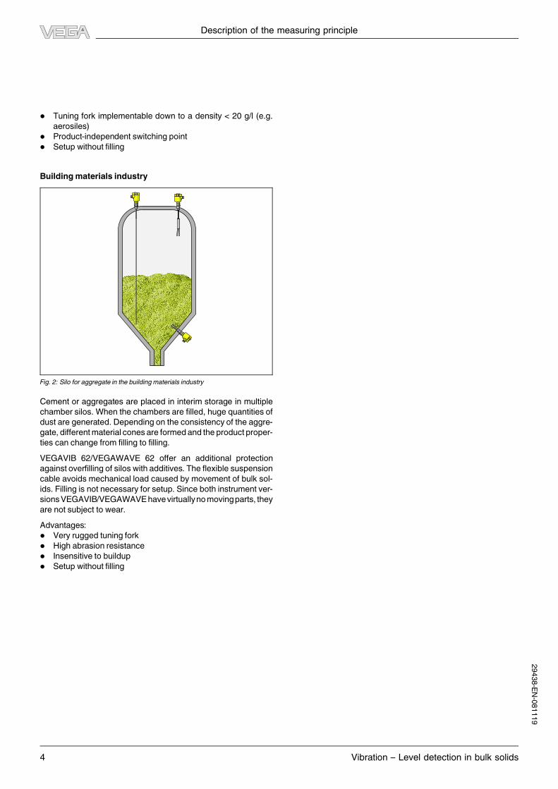
Buildingmaterials industry
Fig. 2: Silo for aggregate in the building materials industry
Cement or aggregates are placed in interim storage in multiple
chamber silos.When the chambers are filled, huge quantities of
dust are generated. Depending on the consistency of the aggre-
gate, differentmaterial cones are formedand the product proper-
ties can change from filling to filling.
VEGAVIB 62/VEGAWAVE 62 offer an additional protection
against overfilling of silos with additives. The flexible suspension
cable avoids mechanical load caused by movement of bulk sol-
ids. Filling is not necessary for setup. Since both instrument ver-
sionsVEGAVIB/VEGAWAVEhavevirtuallynomovingparts, they
are not subject to wear.
Advantages:
l Very rugged tuning fork
l High abrasion resistance
l Insensitive to buildup
l Setup without filling
Description of the measuring principle
4 Vibration – Level detection in bulk solids
29438-EN-081119
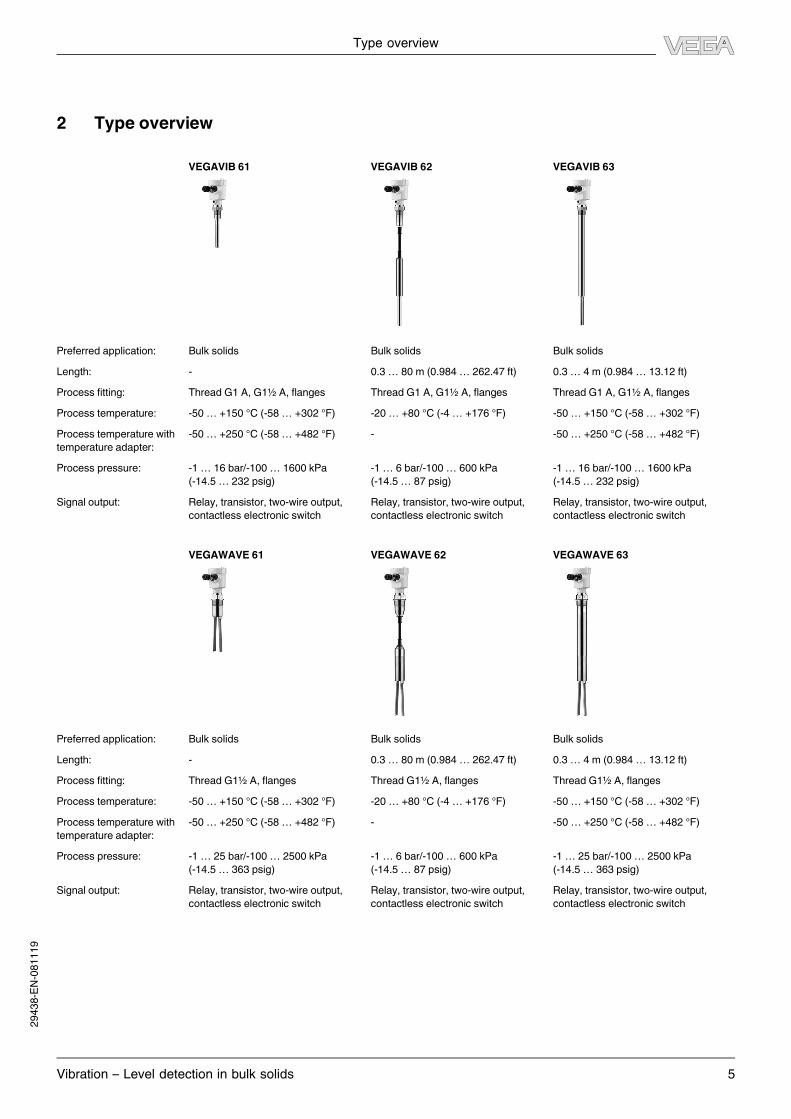
2 Type overview
VEGAVIB 61 VEGAVIB 62 VEGAVIB 63
Preferred application: Bulk solids Bulk solids Bulk solids
Length: - 0.3 … 80m (0.984… 262.47 ft) 0.3 … 4m (0.984… 13.12 ft)
Process fitting: Thread G1 A, G1½ A, flanges Thread G1 A, G1½ A, flanges Thread G1 A, G1½ A, flanges
Process temperature: -50… +150 °C (-58… +302 °F) -20… +80 °C (-4 … +176 °F) -50… +150 °C (-58… +302 °F)
Process temperature with
temperature adapter:
-50… +250 °C (-58… +482 °F) - -50… +250 °C (-58… +482 °F)
Process pressure: -1 … 16 bar/-100… 1600 kPa
(-14.5… 232 psig)
-1 … 6 bar/-100… 600 kPa
(-14.5… 87 psig)
-1 … 16 bar/-100… 1600 kPa
(-14.5… 232 psig)
Signal output: Relay, transistor, two-wire output,
contactless electronic switch
Relay, transistor, two-wire output,
contactless electronic switch
Relay, transistor, two-wire output,
contactless electronic switch
VEGAWAVE 61 VEGAWAVE 62 VEGAWAVE 63
Preferred application: Bulk solids Bulk solids Bulk solids
Length: - 0.3 … 80m (0.984… 262.47 ft) 0.3 … 4m (0.984… 13.12 ft)
Process fitting: Thread G1½ A, flanges Thread G1½ A, flanges Thread G1½ A, flanges
Process temperature: -50… +150 °C (-58… +302 °F) -20… +80 °C (-4 … +176 °F) -50… +150 °C (-58… +302 °F)
Process temperature with
temperature adapter:
-50… +250 °C (-58… +482 °F) - -50… +250 °C (-58… +482 °F)
Process pressure: -1 … 25 bar/-100… 2500 kPa
(-14.5… 363 psig)
-1 … 6 bar/-100… 600 kPa
(-14.5… 87 psig)
-1 … 25 bar/-100… 2500 kPa
(-14.5… 363 psig)
Signal output: Relay, transistor, two-wire output,
contactless electronic switch
Relay, transistor, two-wire output,
contactless electronic switch
Relay, transistor, two-wire output,
contactless electronic switch
Type overview
Vibration – Level detection in bulk solids 5
29438-EN-081119
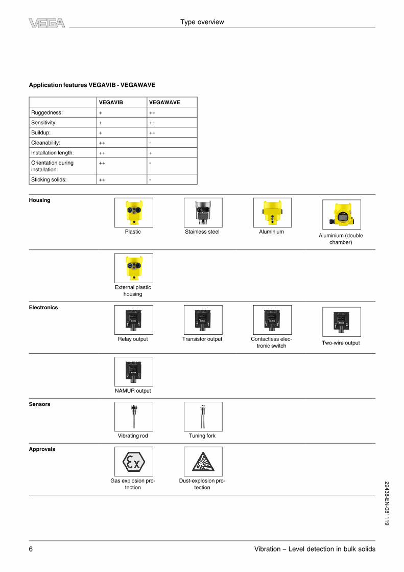
Application features VEGAVIB - VEGAWAVE
VEGAVIB VEGAWAVE
Ruggedness: + ++
Sensitivity: + ++
Buildup: + ++
Cleanability: ++ -
Installation length: ++ +
Orientation during
installation:
++ -
Sticking solids: ++ -
Housing
Plastic Stainless steel AluminiumAluminium (double
chamber)
External plastic
housing
Electronics
Relay output Transistor output Contactless elec-
tronic switchTwo-wire output
NAMUR output
Sensors
Vibrating rod Tuning fork
Approvals
Gas explosion pro-
tection
Dust-explosion pro-
tection
Type overview
6 Vibration – Level detection in bulk solids
29438-EN-081119

3 Mounting instructions
Switching point
In general, VEGAVIB/VEGAWAVE can be installed in any posi-
tion.The instrumentonly has to bemounted in suchaway that the
vibrating element is at the height of the desired switching point.
The only exception is vertical mounting of the tuning fork from
below. In this position there is the danger of solid particles getting
stuck between the fork tines.
Socket
The vibrating element should protrude into the vessel to avoid
buildup.For that reason, avoidusingmountingbosses for flanges
and screwed fittings. This applies particularly to horizontal instal-
lation and use with adhesive products.
Filling opening
Install the instrument in such a way that the vibrating element
does not protrude directly into the filling stream. Should such an
installation location be necessary,mount a suitable baffle above
or in front of the vibrating element, e.g. L80 x 8DIN 1028 (see Fig.
Part "a."). In abrasive solids, mounting according to fig. Part "b."
has proven to be a good solution. The mound that forms in the
concave baffle protects it from abrasion.
20°
a. b.
Fig. 3: Horizontal mounting
a. Convex mounting
b. Concave mounting
Inflowing medium
If VEGAVIB/VEGAWAVE is mounted in the filling stream, un-
wanted false measurement signals can be generated. For this
reason,mountVEGAVIB/VEGAWAVE at a position in the vessel
where no disturbances, e.g. from filling openings, agitators, etc.,
can occur.
Fig. 4: Inflowing medium
Horizontalmounting
To achieve a very precise switching point, you can install VEGA-
VIB/VEGAWAVEhorizontally.However, if theswitchingpointcan
have a tolerance of a few centimeters, we recommend mounting
VEGAVIB/VEGAWAVE approx. 20° inclined to the vessel bottom
to avoid buildup.
Orient the tuning fork of VEGAWAVE so that the product cannot
remain lying on the fork surface. There is a mark on the thread
hexagon for aligning the fork. Make sure that the mark points
upward.
Material cone
In silos containing solids,material cones can form which change
the switching point. Please keep this in mind when installing the
sensor in the vessel. We recommend selecting an installation
location where the vibrating element detects an average value
of the material cone.
The vibrating element must be mounted at a location that takes
the arrangement of the filling and emptying apertures into ac-
count.
Tocompensatemeasurementerrorscausedby thematerialcone
incylindricalvessels, thesensormustbemountedatadistanceof
d/10 from the vessel wall.
Mounting instructions
Vibration – Level detection in bulk solids 7
29438-EN-081119

d d
d10
d10
Fig. 5: Filling and emptying centered
dd 10
1
2
3
Fig. 6: Filling in the center, emptying laterally
1 VEGAVIB/VEGAWAVE
2 Discharge opening
3 Filling opening
Tensile load
With cable version, make sure that the max. permissible tensile
load on the suspension cable is not exceeded. The danger of this
happening exists particularly with very heavy solids and large
meas. lengths. The max. permissible load is stated in chapter
"Technical data".
Agitators
Due to filling or extraction forces, vibrations or similar, the level
switch can be subjected to strong lateral forces. For this reason,
do not use an overly long extension tube for VEGAVIB/VEGA-
WAVE, but check if a VEGAVIB 61 or a VEGAWAVE 61 level
switchcouldn't beused instead,mountedon thesideof thevessel
in horizontal position.
Extreme vibration caused by the process or the equipment, e.g.
by fluidization or beaters in the vessel, can cause the extension
tube of VEGAVIB/VEGAWAVE to vibrate in resonance. This
leads to increasedstress on the upperweld joint.Shoulda longer
tube version be necessary, you can provide a suitable support or
guy directly above the vibrating element to secure the extension
tube.
Thismeasure appliesmainly to applications inEx areas.
Make sure that the tube is not subject to bending stress
due to this measure.
If an installation from above is necessary, check if you can use a
cable version.
Over a longer period of time, strong vibration can damage the
instrument electronics. You can decouple the electronics from
the process by using a remote (displaced) housing.
Flows
To make sure the tuning fork of VEGAWAVE generates as little
resistance as possible to product flow,mount the sensor so that
the surfaces are parallel to the product movement.
1
2
Fig. 7: Flow orientation of the tuning fork
1 Marking with screwed version
2 Direction of flow
Lock fitting
For height adjustment, VEGAVIB/VEGAWAVE in tube version
can be mounted with a lock fitting. This lock fitting is available
for applications in unpressurized areas or as a version for pres-
sures up to 16 bar (232 psig).
Baffle protection against falling rocks
In applications suchas grit chambers or settlingbasins for coarse
sediments, the vibratingelementmust be protectedagainst dam-
age with a suitable baffle.
Mounting instructions
8 Vibration – Level detection in bulk solids
29438-EN-081119
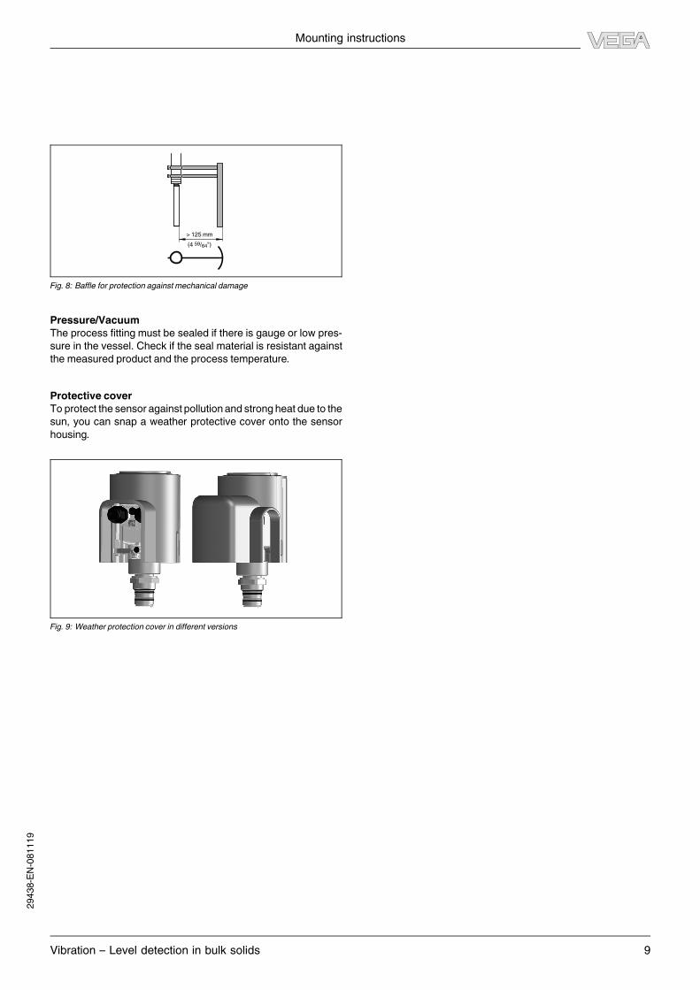
> 125 mm
(4 59/64")
Fig. 8: Baffle for protection against mechanical damage
Pressure/Vacuum
The process fitting must be sealed if there is gauge or low pres-
sure in the vessel. Check if the seal material is resistant against
the measured product and the process temperature.
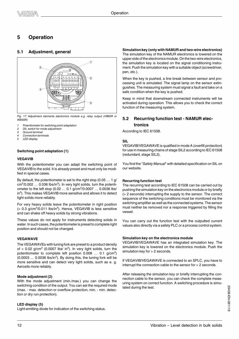
Protective cover
To protect the sensor against pollution and strong heat due to the
sun, you can snap a weather protective cover onto the sensor
housing.
Fig. 9: Weather protection cover in different versions
Mounting instructions
Vibration – Level detection in bulk solids 9
29438-EN-081119

4 Electrical connection
4.1 Preparing the connection
Note safety instructions
Always keep in mind the following safety instructions:
l Connect only in the complete absence of line voltage
Take note of safety instructions for Ex applications
In hazardous areas you should take note of the appro-
priate regulations, conformity and type approval certifi-
cates of the sensors and power supply units.
Select power supply
Connect the power supply according to the following diagrams.
Oscillators with relay output VB60R/WE60R and contactless
electronic switch VB60C/WE60C are designed in protection
class 1. To maintain this protection class, it is absolutely neces-
sary that the ground conductor be connected to the internal
ground terminal. Take note of the general installation regulations.
As a rule, connectVEGAVIB/VEGAWAVE to vessel ground (PA),
or in case of plastic vessels, to the next ground potential. On the
side of the housing there is a ground terminal between the cable
entries. This connection serves to drain off electrostatic charges.
InExapplications, the installationregulations forhazardousareas
must be given priority.
Data for power supply is specified in chapter "Technical data".
Selecting connection cable
The instrument is connectedwithstandardcablewith roundcross
section. An outer cable diameter of 5 … 9 mm (0.2 … 0.35 in)
ensures the seal effect of the cable gland.
If cable with a different diameter or wire cross section is used,
exchange the seal or use an appropriate cable connection.
In hazardous areas, only use approved cable connec-
tions for VEGAVIB/VEGAWAVE.
Select connection cable for Ex applications
Take note of the corresponding installation regulations
for Ex applications.
4.2 Wiring plan
Relay output
We recommend connecting VEGAVIB/VEGAWAVE in such a
way that the switching circuit is open when there is a level signal,
line break or failure (safe condition).
The relays are always shown in non-operative condition.
3
2 1
Fig. 10: Wiring plan, single chamber housing
1 Relay output
2 Relay output
3 Voltage supply
Transistor output
We recommend connecting VEGAVIB/VEGAWAVE in such a
way that the switching circuit is open when there is a level signal,
line break or failure (safe condition).
The instrument is used to control relays, contactors, magnet
valves, warning lights, horns as well as PLC inputs.
1
Fig. 11: Wiring plan, single chamber housing
+ -
+ -
Fig. 12: NPN action
Electrical connection
10 Vibration – Level detection in bulk solids
29438-EN-081119

+ -
+ -
Fig. 13: PNP action
Contactless electronic switch
We recommend connecting VEGAVIB/VEGAWAVE in such a
way that the switching circuit is open when there is a level signal,
line break or failure (safe condition).
The contactless electronic switch is always shown in non-oper-
ative condition.
The instrument is used for direct control of relays, contactors,
magnet valves,warning lights, horns etc. It must not be operated
without an intermediately connected load, because the elec-
tronics would be destroyed if connected directly to the mains. It
is not suitable for connection to low voltage PLC inputs.
Domestic current is temporarily lowered below 1mA after switch-
ing off the load so that contactors,whose holding current is lower
than the constant domestic current of the electronics, are reliably
switched off.
1
Fig. 14: Wiring plan, single chamber housing
1 Shielding
Two-wire output
We recommend connecting VEGAVIB/VEGAWAVE in such a
way that the switching circuit is open when there is a level signal,
line break or failure (safe condition).
For connection to a VEGATOR signal conditioning instrument
dto. Ex. The sensor is powered by the connected VEGATOR
signal conditioning instrument. Further information is available
in chapter "Technical data", "Ex-technical data" are available in
the supplied "Safety informationmanual".
The wiring example is applicable for all suitable signal condition-
ing instruments.
Take note of the operating instructionsmanual of the signal con-
ditioning instrument.Suitable signal conditioning instruments are
listed in chapter "Technical data".
1
Fig. 15: Wiring plan, single chamber housing
1 Voltage supply
NAMUR output
For connection of the amplifier according to NAMUR
(IEC 60947-5-6, EN 50227). You can find further information in
the "Technical data".
1 2
+
+
-
-
Fig. 16: Wiring plan, single chamber housing
Electrical connection
Vibration – Level detection in bulk solids 11
29438-EN-081119
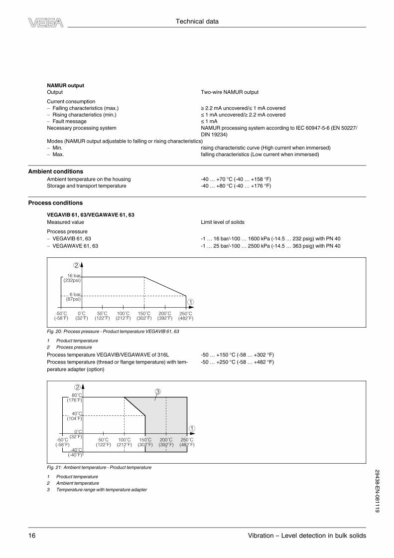
5 Operation
5.1 Adjustment, general
3
4
5
1
2
Fig. 17: Adjustment elements electronics module e.g. relay output (VB60R or
WE60R)
1 Potentiometer for switching point adaptation
2 DIL switch for mode adjustment
3 Ground terminal
4 Connection terminals
5 LED display
Switching point adaptation (1)
VEGAVIB
With the potentiometer you can adapt the switching point of
VEGAVIB to the solid. It is already preset andmust only bemodi-
fied in special cases.
By default, the potentiometer is set to the right stop (0.05… 1 g/
cm³/0.002 … 0.036 lbs/in³). In very light solids, turn the potenti-
ometer to the left stop (0.02 … 0.1 g/cm³/0.0007 … 0.0036 lbs/
in³). This makes VEGAVIBmore sensitive and allows it to detect
light solids more reliably.
For very heavy solids leave the potentiometer in right position
(> 0.3 g/cm³/0.011 lbs/in³). Hence, VEGAVIB is less sensitive
and can shake off heavy solids by strong vibrations.
These values do not apply for instruments detecting solids in
water. Insuchcases, thepotentiometer is preset to complete right
position and should not be changed.
VEGAWAVE
TheVEGAWAVEswith tuning fork are preset to a product density
of > 0.02 g/cm³ (0.0007 lbs/ in³). In very light solids, turn the
potentiometer to complete left position 0.008 … 0.1 g/cm³)
(0.0003 … 0.0036 lbs/in³). By doing this, the tuning fork will be
more sensitive and can detect very light solids, such as e. g.
Aerosils more reliably.
Mode adjustment (2)
With the mode adjustment (min./max.) you can change the
switching condition of the output. You can set the required mode
(max. - max. detection or overflow protection, min. - min. detec-
tion or dry run protection).
LED display (5)
Light-emitting diode for indication of the switching status.
Simulationkey (onlywithNAMUR and two-wire electronics)
The simulation key of the NAMUR electronics is lowered on the
upper sideof theelectronicsmodule.On the two-wireelectronics,
the simulation key is located on the signal conditioning instru-
ment.Push the simulationkeywith a suitable object (screwdriver,
pen, etc.).
When the key is pushed, a line break between sensor and pro-
cessing unit is simulated. The signal lamp on the sensor extin-
guishes. Themeasuring systemmust signal a fault and take on a
safe condition when the key is pushed.
Keep in mind that downstream connected instruments will be
activated during operation. This allows you to check the correct
function of the measuring system.
5.2 Recurring function test - NAMUR elec-
tronics
According to IEC 61508.
SIL
VEGAVIB/VEGAWAVE is qualified inmodeA (overfill protection)
for use inmeasuringchainsof stageSIL2 according to IEC61508
(redundant, stage SIL3).
You find the "SafetyManual"with detailed specification onSIL on
our website.
Recurring function test
The recurring test according to IEC 61508 can be carried out by
pushing the simulationkey on the electronicsmodule or by briefly
(> 2 seconds) interrupting the supply to the sensor. The correct
sequence of the switching conditions must be monitored via the
switchingamplifier aswell as the connected systems.The sensor
must neither be removed nor a response triggered by filling the
vessel.
You can carry out the function test with the outputted current
values also directly via a safetyPLC or a process control system.
Simulation key on the electronicsmodule
VEGAVIB/VEGAWAVE has an integrated simulation key. The
simulation key is lowered on the electronics module. Push the
simulation key for > 2 seconds.
If VEGAVIB/VEGAWAVE is connected to an SPLC, you have to
interrupt the connection cable to the sensor for > 2 seconds.
After releasing the simulation key or briefly interrupting the con-
nection cable to the sensor, you can check the complete meas-
uring system on correct function. A switching procedure is simu-
lated during the test.
Operation
12 Vibration – Level detection in bulk solids
29438-EN-081119

2,2
I/mA
1
3 4,5 t/s
1
2
Fig. 18: Flow chart of the function test - NAMUR electronics
1 Full signal
2 Empty signal
Check if all theswitchingconditionsoccur in thecorrectsequence
and the stated time period. If this is not the case, there is a fault in
themeasuring system. Keep in mind that connected instruments
areactivatedduring the function test.This allowsyou to check the
correct function of the measuring system.
5.3 Recurring function test - Two-wire elec-
tronics
According to IEC 61508.
SIL
VEGAVIB/VEGAWAVE in conjunctionwith a suitable signal con-
ditioning instrument is qualified in mode A (overfill protection) for
use in measuring chains of level SIL2 according to IEC 61508
(redundant, level SIL3).
You find the "SafetyManual"with detailed specification onSIL on
our website.
Recurring function test
The recurring test according to IEC 61508 can be carried out by
pushing the test key on the signal conditioning instrument or by
briefly (> 2 seconds) interrupting the supply to the sensor. The
correct sequence of the switching conditionsmust be monitored
via the two LEDs on the signal conditioning instrument as well as
the connectedsystems.The sensormust neither be removednor
a response triggered by filling the vessel.
You can carry out the function test with the outputted current
values also directly via a safetyPLC or a process control system.
The implementation and switching sequence of the function test
is described also in the operating instructions manual of the ap-
propriate signal conditioning instrument.
Test key on the signal conditioning instrument
Thesignalconditioninginstrumenthasan integratedtest key.The
test key is lowered in the front plate of the signal conditioning
instrument. Push the test key with a suitable object (e.g. screw-
driver, pen etc.) for > 2 seconds.
If VEGAVIB/VEGAWAVE is connected to an SPLC, you have to
interrupt the connection cable to the sensor for > 2 seconds.
After releasing the test key or interrupting the connection cable to
the sensor, the complete measuring system can be checked on
correct function.The followingoperatingconditionsare simulated
during the test:
l Fault message
l Empty signal
l Full signal
16
I/mA
8
2
1,5 3 4,5 t/s
1
2
Fig. 19: Flow chart of the function test - two-wire electronics
1 Full signal
2 Empty signal
Check if all theswitchingconditionsoccur in thecorrectsequence
and the stated time period. If this is not the case, there is a fault in
themeasuring system. Keep in mind that connected instruments
areactivatedduring the function test.This allowsyou to check the
correct function of the measuring system.
Operation
Vibration – Level detection in bulk solids 13
29438-EN-081119

6 Technical data
General data
Material 316L corresponds to 1.4404 or 1.4435
VEGAVIB 61/VEGAWAVE 61
Materials, wetted parts
- Process fitting - thread 316L
- Process fitting - flange 316L
- Seal Klingersil C-4400
- Vibrating element - VEGAVIB 316L/318S13 (1.4462)
- Vibrating element - VEGAWAVE 316L
- Extension tube (VEGAVIB 61): ø 29mm (1.14 in) 316L
- Extension tube (VEGAWAVE 61): ø 43mm (1.692 in) 316L
Materials, non-wetted parts
- Housing Plastic PBT (polyester), Alu die-casting powder-coated, 316L
- Seal between housing and housing cover NBR (stainless steel housing), silicone (Alu/plastic housing)
- Ground terminal 316Ti/316L
Weight
- VEGAVIB 61 - plastic housing 1150 g (40 oz)
- VEGAVIB 61 - Aluminium housing 1600 g (56 oz)
- VEGAVIB 61 - stainless steel housing 1950 g (69 oz)
- VEGAWAVE 61 - plastic housing 1500 g (53 oz)
- VEGAWAVE 61 - Aluminium housing 1950 g (69 oz)
- VEGAWAVE 61 - stainless steel housing 2300 g (81 oz)
Max. lateral load 400 N (90 lbf)
VEGAVIB 62/VEGAWAVE 62
Materials, wetted parts
- Process fitting - thread 316L
- Process fitting - flange 316L
- Seal CR, CSM
- Vibrating element - VEGAVIB 316L/318S13 (1.4462)
- Vibrating element - VEGAWAVE 316L
- Suspension cable (-20 … +80 °C/-4 … +176 °F) PUR
- Suspension cable - optionally (-40… +150 °C/-40… +302 °F) FEP (not for solid detection in water)
Materials, non-wetted parts
- Housing Plastic PBT (polyester), Alu die-casting powder-coated, 316L
- Seal between housing and housing cover NBR (stainless steel housing), silicone (Alu/plastic housing)
- Ground terminal 316Ti/316L
Weight
- VEGAVIB 62 - plastic housing 1150 g (40 oz)
- VEGAVIB 62 - Aluminium housing 1600 g (56 oz)
- VEGAVIB 62 - stainless steel housing 1950 g (69 oz)
- VEGAWAVE 62 - plastic housing 1500 g (53 oz)
- VEGAWAVE 62 - Aluminium housing 1950 g (69 oz)
- VEGAWAVE 62 - stainless steel housing 2300 g (81 oz)
- Suspension cable 165 g/m (1.8 oz/ft)
Max. permissible tensile load 3000 N (675 lbs)
Sensor length 0.48 … 80 m (1.575… 262.47 ft)
VEGAVIB 63/VEGAWAVE 63
Materials, wetted parts
- Process fitting - thread 316L
- Process fitting - flange 316L
- Seal Klingersil C-4400
- Vibrating element - VEGAVIB 316L/318S13 (1.4462)
- Vibrating element - VEGAWAVE 316L
- Extension tube (VEGAVIB 63): ø 29mm (1.14 in) 316L
- Extension tube (VEGAWAVE 63): ø 43mm (1.692 in) 316L
Materials, non-wetted parts
- Housing Plastic PBT (polyester), Alu die-casting powder-coated, 316L
- Seal between housing and housing cover NBR (stainless steel housing), silicone (Alu/plastic housing)
- Ground terminal 316Ti/316L
Technical data
14 Vibration – Level detection in bulk solids
29438-EN-081119

Weight
- VEGAVIB 63 - plastic housing 1150 g (40 oz)
- VEGAVIB 63 - Aluminium housing 1600 g (56 oz)
- VEGAVIB 63 - stainless steel housing 1950 g (69 oz)
- VEGAWAVE 63 - plastic housing 1500 g (53 oz)
- VEGAWAVE 63 - Aluminium housing 1950 g (69 oz)
- VEGAWAVE 63 - stainless steel housing 2300 g (81 oz)
- Extension tube (VEGAVIB 63): ø 29mm (1.14 in) 1450 g/m (15.6 oz/ft)
- Extension tube (VEGAWAVE 63): ø 43mm (1.692 in) 2000 g/m (21.5 oz/ft)
Sensor length 0.3 … 4m (0.984… 13.12 ft)
Max. lateral load
- VEGAVIB 63 140 Nm (103 lbf ft), 400 N (90 lbf)
- VEGAWAVE 63 290 Nm (214 lbf ft), 600 N (135 lbf)
Output variable
Relay output
Output Relay output (DPDT), 2 floating spdts
Turn-on voltage
- Min. 10mV
- Max. 253 V AC, 253 V DC
Switching current
- Min. 10 µA
- Max. 3 A AC, 1 A DC
Breaking capacity
- Max. 1250 VA, 50W
Contact material (relay contacts) AgCdO and Au plated
Modes (adjustable) Min./Max.
Delay time approx.
- When immersed 0.5 s
- When laid bare 1 s
Transistor output
Output floating transistor output, overload and permanently shortcircuit proof
Load current < 400mA
Turn-on voltage < 55 V DC
Blocking current < 100 µA
Modes (adjustable) Min./Max.
Delay time approx.
- When immersed 0.5 s
- When laid bare 1 s
Contactless electronic switch
Output Contactless electronic switch
Modes (adjustable) Min./Max.
Delay time approx.
- When immersed 0.5 s
- When laid bare 1 s
Two-wire output
Output Two-wire output
Suitable signal conditioning instruments VEGATOR 536Ex, 537Ex, 636Ex
Output signal
- Mode min. Vibrating element uncovered: 16mA ±1 mA, vibrating element covered:
8mA ±1 mA
- Mode max. Vibrating element uncovered: 8mA ±1 mA, vibrating element covered:
16mA ±1 mA
- Fault message < 2mA
Modes (adjustable) Min./Max.
Delay time approx.
- When immersed 0.5 s
- When laid bare 1 s
Technical data
Vibration – Level detection in bulk solids 15
29438-EN-081119
Technical data
16 Vibration – Level detection in bulk solids
NAMUR output
Output Two-wire NAMUR output
Current consumption
- Falling characteristics (max.) ≥ 2.2 mA uncovered/≤ 1 mA covered
- Rising characteristics (min.) ≤ 1mA uncovered/≥ 2.2 mA covered
- Fault message ≤ 1mA
Necessary processing system NAMUR processing system according to IEC 60947-5-6 (EN 50227/
DIN 19234)
Modes (NAMUR output adjustable to falling or rising characteristics)
- Min. rising characteristic curve (High current when immersed)
- Max. falling characteristics (Low current when immersed)
Ambient conditions
Ambient temperature on the housing -40… +70 °C (-40… +158 °F)
Storage and transport temperature -40… +80 °C (-40… +176 °F)
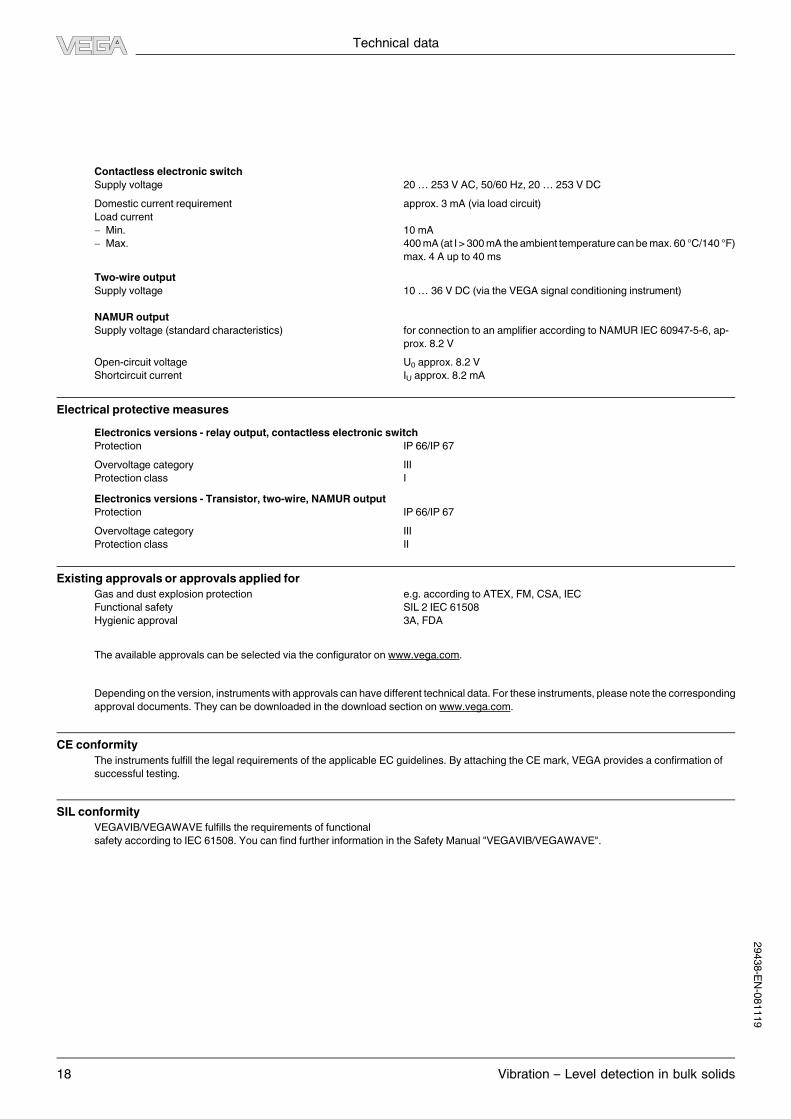
Process conditions
VEGAVIB 61, 63/VEGAWAVE 61, 63
Measured value Limit level of solids
Process pressure
- VEGAVIB 61, 63 -1 … 16 bar/-100… 1600 kPa (-14.5… 232 psig) with PN 40
- VEGAWAVE 61, 63 -1 … 25 bar/-100… 2500 kPa (-14.5… 363 psig) with PN 40
6 bar(87psi)
-50˚C(-58˚F)
16 bar(232psi)
50˚C(122˚F)
100˚C(212˚F)
0˚C(32˚F)
150˚C(302˚F)
200˚C(392˚F)
250˚C(482˚F)
1
2
Fig. 20: Process pressure - Product temperature VEGAVIB 61, 63
1 Product temperature
2 Process pressure
Process temperature VEGAVIB/VEGAWAVE of 316L -50… +150 °C (-58… +302 °F)
Process temperature (thread or flange temperature) with tem-
perature adapter (option)
-50… +250 °C (-58… +482 °F)
1
23
-50˚C(-58˚F)
50˚C(122˚F)
40˚C(104˚F)
-40˚C(-40˚F)
80˚C(176˚F)
0˚C(32˚F)
100˚C(212˚F)
150˚C(302˚F)
200˚C(392˚F)
250˚C(482˚F)
Fig. 21: Ambient temperature - Product temperature
1 Product temperature
2 Ambient temperature
3 Temperature range with temperature adapter
29438-EN-081119

Technical data
Vibration – Level detection in bulk solids 17
Product density
- VEGAVIB 61, 63 > 0.02 g/cm³ (0.0007 lbs/in³)
- VEGAWAVE 61, 63 > 0.008 g/cm³ (0.0003 lbs/in³)
Granular size
- VEGAVIB 61, 63 no limitation1)
- VEGAWAVE 61, 63 max. 10mm (0.4 in)
VEGAVIB 62/VEGAWAVE 62
Measured value Limit level of solids
Process pressure -1 … 6 bar/-100… 600 kPa (-14.5 … 87 psig) with PN 40
Process temperature VEGAVIB 62, VEGAWAVE 62 of 316L -20… +80 °C (-4 … +176 °F)
Product density
- VEGAVIB 62 > 0.02 g/cm³ (0.0007 lbs/in³)
- VEGAWAVE 62 > 0.008 g/cm³ (0.0003 lbs/in³)
Granular size
- VEGAVIB 62 no limitation2)
- VEGAWAVE 62 max. 10mm (0.4 in)
Electromechanical data
Cable entry/plug (dependent on the version)
- Single chamber housing l 1 x cable entryM20 x 1.5 (cable: ø 5 … 9mm), 1 x blind stopper
M20 x 1.5; attached 1 x cable entryM20 x 1.5
or:l 1 x cable entry½NPT,1 x blindstopper½NPT,1 x cableentry½NPT
or:l 1 x plugM12 x 1; 1 x blind stopperM20 x 1.5
Spring-loaded terminals for wire cross-section up to 1.5mm² (AWG 16)
Adjustment elements
Electronics versions - relay, transistor output, contactless electronic switch
Mode switch
- Min. Min. detection or dry run protection
- Max. Max. detection or overflow protection
Electronics version - two-wire output
Mode switch
- Min. Vibrating element uncovered: 16mA ±1 mA
Vibrating element covered: 8 mA ±1mA
- Max. Vibrating element uncovered: 8mA ±1 mA
Vibrating element covered: 16 mA ±1 mA
Electronics version - NAMUR output
Mode switch
- Min. rising characteristic curve (High current when immersed)
- Max. falling characteristics (Low current when immersed)
Voltage supply
Relay output
Supply voltage 20… 253 V AC, 50/60 Hz, 20… 72 V DC (at U > 60 V DC, the ambient
temperature can be max. 50 °C/122 °F)
Power consumption 1… 8 VA (AC), approx. 1.3W (DC)
Transistor output
Supply voltage 10… 55 V DC
Max. power consumption 0.5 W
1)max. 20 mm (0.8 in) with product density < 0.05 g/cm³ (0.002 lbs/in³).
2)max. 20 mm (0.8 in) with product density < 0.05 g/cm³ (0.002 lbs/in³).2
9438-EN-081119
Technical data
18 Vibration – Level detection in bulk solids
Contactless electronic switch
Supply voltage 20… 253 V AC, 50/60 Hz, 20… 253 V DC
Domestic current requirement approx. 3 mA (via load circuit)
Load current
- Min. 10mA
- Max. 400mA (at I> 300mA the ambient temperature canbemax.60 °C/140 °F)
max. 4 A up to 40ms
Two-wire output
Supply voltage 10… 36 V DC (via the VEGA signal conditioning instrument)
NAMUR output
Supply voltage (standard characteristics) for connection to an amplifier according to NAMUR IEC 60947-5-6, ap-
prox. 8.2 V
Open-circuit voltage U0 approx. 8.2 V
Shortcircuit current IU approx. 8.2 mA
Electrical protective measures
Electronics versions - relay output, contactless electronic switch
Protection IP 66/IP 67
Overvoltage category III
Protection class I
Electronics versions - Transistor, two-wire, NAMUR output
Protection IP 66/IP 67
Overvoltage category III
Protection class II
Existing approvals or approvals applied for
Gas and dust explosion protection e.g. according to ATEX, FM, CSA, IEC
Functional safety SIL 2 IEC 61508
Hygienic approval 3A, FDA
The available approvals can be selected via the configurator on www.vega.com.
Depending on the version, instrumentswith approvals can have different technical data. For these instruments, please note the corresponding
approval documents. They can be downloaded in the download section on www.vega.com.
CE conformity
The instruments fulfill the legal requirements of the applicable EC guidelines. By attaching the CEmark, VEGA provides a confirmation of
successful testing.
SIL conformity
VEGAVIB/VEGAWAVE fulfills the requirements of functional
safety according to IEC 61508. You can find further information in the SafetyManual "VEGAVIB/VEGAWAVE".
29438-EN-081119
Dimensions
Vibration – Level detection in bulk solids 19
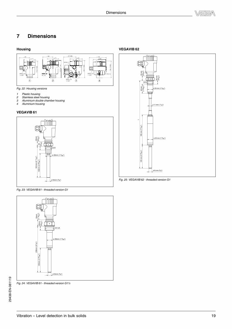
7 Dimensions
Housing
ø 77
~ 69
117
(*128)
20x1,5
~ 116
116
(*125)
~ 87 (96)
ø 84
120
(*129)
~ 69
112 (
*123)
½ ½ ½ NPT
M20x1,5/
½ NPT
M16x1,5
1 2 3 4
Fig. 22: Housing versions
1 Plastic housing
2 Stainless steel housing
3 Aluminium double chamber housing
4 Aluminium housing
VEGAVIB 61
25
mm
(63/ 6
4")
20
(25/ 3
2)
16
1m
m (
6 1
1/ 3
2")
12
5m
m (
4 5
9/ 6
4")
ø16mm (5/8")
ø 29mm (1 9/64")
G1A
Fig. 23: VEGAVIB 61 - threaded versionG1
33
mm
(1 1
9/ 6
4")
22
mm
(55/ 6
4")
12
5m
m (
4 5
9/ 6
4")
23
8m
m (
9 3
/ 8")
ø16mm (5/8")
G1½A
ø 29mm (1 9/64")
Fig. 24: VEGAVIB 61 - threaded versionG1½
VEGAVIB 62
49
mm
(1 5
9/ 6
4")
25
mm
(63/ 6
4")
20
mm
(25/ 3
2")
L
18
5 m
m (
7 9
/ 32")
12
5 m
m (
4 5
9/ 6
4")
ø16 mm (5/8")
G1A
ø 29 mm (1 9/64")
ø 29 mm (1 9/64")
ø 11 mm ( 7/16")
Fig. 25: VEGAVIB 62 - threaded versionG1
29438-EN-081119
Dimensions
20 Vibration – Level detection in bulk solids
22
mm
(55/ 6
4")
54
mm
(2 1
/ 8")
L
18
5m
m (
7 9
/ 32")
12
5m
m (
4 5
9/ 6
4")
ø16mm (5/8")
G1½A
ø 29mm (1 9/64")
ø 29mm (1 9/64")
ø 11mm ( 7/16")
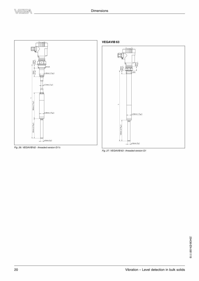
Fig. 26: VEGAVIB 62 - threaded versionG1½
VEGAVIB 63
20
mm
(25/ 3
2")
25
mm
(63/ 6
4")
L
12
5m
m (
4 5
9/ 6
4")
ø16mm (5/8")
G1A
ø 29mm (1 9/64")
Fig. 27: VEGAVIB 63 - threaded versionG1
29438-EN-081119
Dimensions
Vibration – Level detection in bulk solids 21
22
mm
(55/ 6
4")
33
mm
(1 1
9/ 6
4")
L
12
5m
m (
4 5
9/ 6
4")
ø16mm (5/8")
G1½A
ø 29mm (1 9/64")
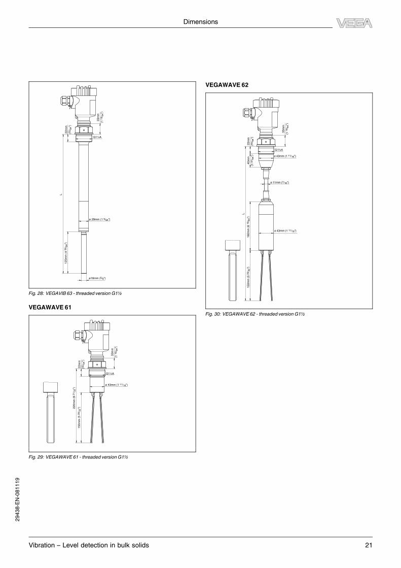
Fig. 28: VEGAVIB 63 - threaded versionG1½
VEGAWAVE 61
22
mm
(55/ 6
4")
33
mm
(1 1
9/ 6
4")
22
0m
m (
8 2
1/ 3
2")
15
0m
m (
5 2
9/ 3
2")
G1½A
ø 43mm (1 11/16")
Fig. 29: VEGAWAVE 61 - threaded versionG1½
VEGAWAVE 62
15
0m
m (
5 2
9/ 3
2")
L
22
mm
(55/ 6
4")
40
mm
(1 3
7/ 6
4")
33
mm
(1 1
9/ 6
4")
G1½A
ø 43mm (1 11/16")
ø 11mm (7/16")
ø 43mm (1 11/16")
16
0m
m (
6 1
9/ 6
4")
Fig. 30: VEGAWAVE 62 - threaded versionG1½
29438-EN-081119

Dimensions
22 Vibration – Level detection in bulk solids
VEGAWAVE 63
22
mm
(55/ 6
4")
33
mm
(1 1
9/ 6
4")
G1½A
15
0m
m (
5 2
9/ 3
2")
L
ø 43mm (1 11/16")
Fig. 31: VEGAWAVE 63 - threaded versionG1½
Temperature adapter
ø 34 mm
(1 11/32")
17
8 m
m (
7 1
/ 64")
Fig. 32: Temperature adapter (only for VEGAVIB 61, 63 and VEGAWAVE 61, 63)
29438-EN-081119

Product code
Vibration – Level detection in bulk solids 23
8 Product code
VEGAVIB 61
Approval
XX without
CX ATEX II 1G, 1/2G, 2G EEx ia IIC T6 1)
CK ATEX II 1G, 1/2G, 2G EEx ia IIC T6+ATEX II 1/2D IP6X T 2)
LX ATEX II 1/2G, 2G EEx d IIC T6 3)
GX ATEX II 1/2 D IP6X T 4)
Version / Process temperature
A Standard / -50...150°C
B With adapter / -50...250°C
C Detection of solids in water / -50...150°C
Process fitting / Material
GC Thread G1A PN16 / 316L
NC Thread 1NPT PN16 / 316L
GD Thread G1½A PN16 / 316L switching point as VIB51
ND Thread 1½NPT PN16 / 316L switching point as VIB51
GG Thread G1½A PN16 / 316L
NG Thread 1½NPT PN16 / 316L
Electronics
C Contactless electronic switch 20...253VAC/DC
R Relay (DPDT) 20...72VDC/20...253VAC(3A)
T Transistor (NPN/PNP) 10...55VDC
Z Two-wire 8/16 mA 10...36VDC
N NAMUR signal
Housing / Protection
K Plastic / IP66/IP67
A Aluminium / IP66/IP68 (0.2 bar)
8 StSt (electropolished) 316L / IP66/IP68 (0.2bar)
Cable entry / Plug connection
M M20x1.5 / without
N ½NPT / without
Additional equipment
X Without
VB61.
1)Only in conjunction with Electronics "Z" and "N"
2)Only in conjunction with Electronics "Z" and "N", not in conjunction with Housing / Protection "K"
3)Only in conjunction with Housing / Protection "A"
4)Not in conjunction with Housing / Protection "K"
VEGAVIB 62
Approval
XX without
CX ATEX II 1G, 1/2G, 2G EEx ia IIC T6 1)
CK ATEX II 1G, 1/2G, 2G EEx ia IIC T6+ATEX II 1/2D IP6X T 2)
GX ATEX II 1/2 D IP6X T 3)
Version / Process temperature
T Standard / -20...80°C
C Detection of solids in water / -20...80°C
Process fitting / Material
GC Thread G1A PN16 / 316L
NC Thread 1NPT PN16 / 316L
GD Thread G1½A PN16 / 316L
ND Thread 1½NPT PN16 / 316L
Electronics
C Contactless electronic switch 20...253VAC/DC
R Relay (DPDT) 20...72VDC/20...253VAC(3A)
T Transistor (NPN/PNP) 10...55VDC
Z Two-wire 8/16 mA 10...36VDC
N NAMUR signal
Housing / Protection
K Plastic / IP66/IP67
A Aluminium / IP66/IP68 (0.2 bar)
8 StSt (electropolished) 316L / IP66/IP68 (0.2bar)
Cable entry / Plug connection
M M20x1.5 / without
N ½NPT / without
Additional equipment
X Without
VB62.
1)Only in conjunction with Electronics "Z" and "N"
2)Only in conjunction with Electronics "Z" and "N", not in conjunction with Housing / Protection "K"
3)Not in conjunction with Housing / Protection "K"
VEGAVIB 63
Approval
XX without
CX ATEX II 1G, 1/2G, 2G EEx ia IIC T6 1)
CK ATEX II 1G, 1/2G, 2G EEx ia IIC T6+ATEX II 1/2D IP6X T 2)
LX ATEX II 1/2G, 2G EEx d IIC T6 3)
GX ATEX II 1/2 D IP6X T 4)
Version / Process temperature
A Standard / -50...150°C
B With adapter / -50...250°C
C Detection of solids in water / -50...150°C
Process fitting / Material
GC Thread G1A PN16 / 316L
NC Thread 1NPT PN16 / 316L
GD Thread G1½A PN16 / 316L
ND Thread 1½NPT PN16 / 316L
Electronics
C Contactless electronic switch 20...253VAC/DC
R Relay (DPDT) 20...72VDC/20...253VAC(3A)
T Transistor (NPN/PNP) 10...55VDC
Z Two-wire 8/16 mA 10...36VDC
N NAMUR signal
Housing / Protection
K Plastic / IP66/IP67
A Aluminium / IP66/IP68 (0.2 bar) .
8 StSt (electropolished) 316L / IP66/IP68 (0.2bar)
Cable entry / Plug connection
M M20x1.5 / without
N ½NPT / without
Additional equipment
X Without
VB63.
1)Only in conjunction with Electronics "Z" and "N"
2)Only in conjunction with Electronics "Z" and "N", not in conjunction with Housing / Protection "K"
3)Only in conjunction with Housing / Protection "A"
4)Not in conjunction with Housing / Protection "K"
VEGAWAVE 61
Approval
XX without
CX ATEX II 1G, 1/2G, 2G EEx ia IIC T6 1)
CK ATEX II 1G, 1/2G, 2G EEx ia IIC T6+ATEX II 1/2D IP6X T 2)
LX ATEX II 1/2G, 2G EEx d IIC T6 3)
GX ATEX II 1/2 D IP6X T 4)
Version / Process temperature
A Standard / -50...150°C
B With adapter / -50...250°C
C Detection of solids in water / -50...150°C
Process fitting / Material
GD Thread G1½A PN25 / 316L
ND Thread 1½NPT PN25 / 316L
Electronics
C Contactless electronic switch 20...253VAC/DC
R Relay (DPDT) 20...72VDC/20...253VAC(3A)
T Transistor (NPN/PNP) 10...55VDC
Z Two-wire 8/16 mA 10...36VDC
N NAMUR signal
Housing / Protection
K Plastic / IP66/IP67
A Aluminium / IP66/IP68 (0.2 bar)
8 StSt (electropolished) 316L / IP66/IP68 (0.2bar)
Cable entry / Plug connection
M M20x1.5 / without
N ½NPT / without
Additional equipment
X Without
WE61.
1)Only in conjunction with Electronics "Z" and "N"
2)Only in conjunction with Electronics "Z" and "N", not in conjunction with Housing / Protection "K"
3)Only in conjunction with Housing / Protection "A"
4)Not in conjunction with Housing / Protection "K"
29438-EN-081119

24 Vibration – Level detection in bulk solids
VEGAWAVE 62
Approval
XX without
CX ATEX II 1G, 1/2G, 2G EEx ia IIC T6 1)
CK ATEX II 1G, 1/2G, 2G EEx ia IIC T6+ATEX II 1/2D IP6X T 2)
GX ATEX II 1/2 D IP6X T 3)
Version / Process temperature
T Standard / -20...80°C
C Detection of solids in water / -20...80°C
Process fitting / Material
GD Thread G1½A PN16 / 316L
ND Thread 1½NPT PN16 / 316L
Electronics
C Contactless electronic switch 20...253VAC/DC
R Relay (DPDT) 20...72VDC/20...253VAC(3A)
T Transistor (NPN/PNP) 10...55VDC
Z Two-wire 8/16 mA 10...36VDC
N NAMUR signal
Housing / Protection
K Plastic / IP66/IP67
A Aluminium / IP66/IP68 (0.2 bar)
8 StSt (electropolished) 316L / IP66/IP68 (0.2bar)
Cable entry / Plug connection
M M20x1.5 / without
N ½NPT / without
Additional equipment
X Without
WE62.
1)Only in conjunction with Electronics "Z" and "N"
2)Only in conjunction with Electronics "Z" and "N", not in conjunction with Housing / Protection "K"
3)Not in conjunction with Housing / Protection "K"
VEGAWAVE 63
Approval
XX without
CX ATEX II 1G, 1/2G, 2G EEx ia IIC T6 1)
CK ATEX II 1G, 1/2G, 2G EEx ia IIC T6+ATEX II 1/2D IP6X T 2)
LX ATEX II 1/2G, 2G EEx d IIC T6 3)
GX ATEX II 1/2 D IP6X T 4)
Version / Process temperature
A Standard / -50...150°C
B With adapter / -50...250°C
C Detection of solids in water / -50...150°C
Process fitting / Material
GD Thread G1½A PN25 / 316L
ND Thread 1½NPT PN25 / 316L
Electronics
C Contactless electronic switch 20...253VAC/DC
R Relay (DPDT) 20...72VDC/20...253VAC(3A)
T Transistor (NPN/PNP) 10...55VDC
Z Two-wire 8/16 mA 10...36VDC
N NAMUR signal
Housing / Protection
K Plastic / IP66/IP67
A Aluminium / IP66/IP68 (0.2 bar)
8 StSt (electropolished) 316L / IP66/IP68 (0.2bar)
Cable entry / Plug connection
M M20x1.5 / without
N ½NPT / without
Additional equipment
X Without
WE63.
1)Only in conjunction with Electronics "Z" and "N"
2)Only in conjunction with Electronics "Z" and "N", not in conjunction with Housing / Protection "K"
3)Only in conjunction with Housing / Protection "A"
4)Not in conjunction with Housing / Protection "K"
29438-EN-081119

Vibration – Level detection in bulk solids 25
29438-EN-081119

26 Vibration – Level detection in bulk solids
29438-EN-081119

Vibration – Level detection in bulk solids 27
29438-EN-081119
VEGA Grieshaber KG
Am Hohenstein 113
77761 Schiltach
Germany
Phone +49 7836 50-0
Fax +49 7836 50-201
E-Mail: [email protected]
www.vega.com
You can find at www.vega.com
downloads of the following
l operating instructions manuals
l menu schematics
l software
l certificates
l approvals
and much, much more
Subject to change without prior notice 29438-EN-081119