product catalogue - franke gmbh · pdf filestandard program product catalogue . 2. ... rotary...
TRANSCRIPT

Wire Race Bearings Slim Bearings Linear Systems
Standard program
Product Catalogue

2

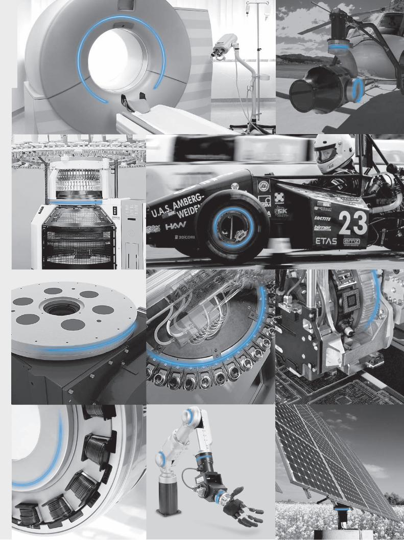
Light Bearings for Innovation
From the inventor of Wire Race Bearings
In the patent specification dated 3 March 1934, Erich Franke defined his ground-breaking invention as follows: "ball bearing, characterized by the fact that the ball raceways for the balls consist of four open rings of steel wire, which are embedded directly in grooves of the two bodies supported by the bearing."
Customized solutions since 1934
Franke Wire Race Bearings were first used as extremely space-saving bearings for a complex optical device by the firm Zeiss. It marked the begin of our success story across all industries.
3

4

Franke around the world
One-stop service is among the fundamental principles we apply to our business. Franke has established representations and forged partnerships worldwide to deliver advice and all Franke products precisely where you need them.
Head office
Representatives
5

Line
ar S
yste
ms
Wir
e R
ace
Bea
ring
s
Wire Race BearingsStructure and benefits
Characteristics Diameter range
Bearing Elements LELLER
• Maximum possible integration capacity• Series application to meet cost constraints• Greatest possible flexibility based on preload,
runnability and diameter ranges
• Infinitely variable from 70 to 2000 mm
Slim Bearings LSALSBLSC
• Simple, compact integration, LSA, infinitely variable Ø range
• Cost-effective alternative to standard slim bearings• Not preloaded bearings
• LSA infinitely variable from 3" to 30"• LSB graded from 4.75" to 25"
(rated slim bearing dimensions)• LSC infinitely variable from 5,5" to 30"
Bearing Assemblies LVALVBLVC
LVDLVE
• Ready to install in a large selection range • Preloaded free from clearance
(optimized for rigidity, speed and service life) • Available on short notice• LVC type for high speeds
• Infinitely variable from 100 to 1800 mm • Selected diameters available ex works
Rotary systems LTALTB
• Rotary tables for fast-rotating or highly-precise handling and measurement tasks
• Bearing assemblies with direct drive• All systems complete with motor and control,
available as one-stop solutions
• Rotary tables LTA and LTB graded from 100 to 400 mm
Accessories • Washers for bearing assemblies• Ball cages made of various materials • Various kinds of seal
Technical information
• Selection of suitable bearing• Calculation of stat./dynam. safety • Data on processing the bearing bed for bearing
elements and slim bearings• Instructions on assembly and fastening
Linear Systems Structure and benefits
Characteristics Stroke lengths
Linear guides FDAFDBFDCFDD
FDEFDGFDH
• Aluminium roller guides in various designs (e.g. non-corrosive, lubricant-free, LowCost)
• All variations with inserted steel raceways • Large rollers for smooth and quiet running • Individually adjustable slide resistance
• Infinitely variable from 200 to 4000 mm in one piece, infinitely coupled for longer stroke lengths
Linear tables Linear modules
FTBFTCFTD
FTIFTH
• Motorized modules with stroke lengths up to 7 m• Toothed belt and spindle drive• Linear module FTH with direct drive• LowCost module FTI with infinitely variable stroke lengths• Linear tables for precise positioning
• Linear tables FTB, infinitely variable from 100 to 1500 mm
• Linear modules with spindle/toothed belt drive, infinitely variable from 100 to 7000 mm
• FTH with direct drive from 170 to 3625 mm
Accessories • Cassette with clamping device• Scraper and bellows to prevent dirt• Cap on the fastening bores• Fastening for the linear modules• Drive shafts and limit switches
Technical information
• Accuracies, slide resistances • Instructions for assembly and adjustment• Details on motorization and control of the linear modules• Calculation of the static safety and service life
6

Wire Race BearingsStructure and benefits
Characteristics Diameter range
Bearing Elements LELLER
• Maximum possible integration capacity• Series application to meet cost constraints• Greatest possible flexibility based on preload,
runnability and diameter ranges
• Infinitely variable from 70 to 2000 mm
Slim Bearings LSALSBLSC
• Simple, compact integration, LSA, infinitely variable Ø range
• Cost-effective alternative to standard slim bearings• Not preloaded bearings
• LSA infinitely variable from 3" to 30"• LSB graded from 4.75" to 25"
(rated slim bearing dimensions)• LSC infinitely variable from 5,5" to 30"
Bearing Assemblies LVALVBLVC
LVDLVE
• Ready to install in a large selection range • Preloaded free from clearance
(optimized for rigidity, speed and service life) • Available on short notice• LVC type for high speeds
• Infinitely variable from 100 to 1800 mm • Selected diameters available ex works
Rotary systems LTALTB
• Rotary tables for fast-rotating or highly-precise handling and measurement tasks
• Bearing assemblies with direct drive• All systems complete with motor and control,
available as one-stop solutions
• Rotary tables LTA and LTB graded from 100 to 400 mm
Accessories • Washers for bearing assemblies• Ball cages made of various materials • Various kinds of seal
Technical information
• Selection of suitable bearing• Calculation of stat./dynam. safety • Data on processing the bearing bed for bearing
elements and slim bearings• Instructions on assembly and fastening
Linear Systems Structure and benefits
Characteristics Stroke lengths
Linear guides FDAFDBFDCFDD
FDEFDGFDH
• Aluminium roller guides in various designs (e.g. non-corrosive, lubricant-free, LowCost)
• All variations with inserted steel raceways • Large rollers for smooth and quiet running • Individually adjustable slide resistance
• Infinitely variable from 200 to 4000 mm in one piece, infinitely coupled for longer stroke lengths
Linear tables Linear modules
FTBFTCFTD
FTIFTH
• Motorized modules with stroke lengths up to 7 m• Toothed belt and spindle drive• Linear module FTH with direct drive• LowCost module FTI with infinitely variable stroke lengths• Linear tables for precise positioning
• Linear tables FTB, infinitely variable from 100 to 1500 mm
• Linear modules with spindle/toothed belt drive, infinitely variable from 100 to 7000 mm
• FTH with direct drive from 170 to 3625 mm
Accessories • Cassette with clamping device• Scraper and bellows to prevent dirt• Cap on the fastening bores• Fastening for the linear modules• Drive shafts and limit switches
Technical information
• Accuracies, slide resistances • Instructions for assembly and adjustment• Details on motorization and control of the linear modules• Calculation of the static safety and service life
Ove
rvie
w
777

Wire race ring
Rolling element
Rolling element cage
Bearing element
The video Function principle of Wire Race Bearings at YouTube Search term "Franke Wire Race Bearings"
8

Bearing element
Inner ringOuter ring
Mating structure
Wire Race Bearings
Franke Wire Race Bearings are delivered either separately as bearing elements (only race rings, rolling elements, cage) or together with the mating structure as ready-to-use bearing assemblies.In both cases the rolling process does not take place like in standard bearings directly between the rolling element and the mating structure, but instead with low friction on the race rings.This special construction principle produces an extremely compact and resilient bearing that can be adjusted to fit even the smallest mounting space. We offer individually customized solutions for your specific application, in addition to the standard program. The Wire Race Bearings are infinitely variable in size and can be customized individually; the material of the mating structure can be designed freely to suit the requirements.
Bearing assembly
Wir
e R
ace
B
eari
ngs
9

10

Why Wire Race Bearings?
Adjusting ringSolid adjustmentWashers
Franke Wire Race Bearings offer you a broad range of options to construct special bearings customized to suit your individual application, in addition to the standard program.
4-point system – resilience from all directionsThe arrangement of the race rings ensures even loading resilience of the bearings from all directions. This applies equally to the double row angular contact ball bearings.
Freely adjustable rotational resistance – a preloaded systemFranke Wire Race Bearings can be aligned and adjusted. This takes place using washers, solid adjustment or adjusting ring.
Compact design – minimum mounting spaceFranke Wire Race Bearings can be integrated directly into your mating design. Our smallest bearing element requires a mere 4 x 7 mm mounting space.
Wir
e R
ace
B
eari
ngs
11

Angular contact ball bearings for highly-dynamic applicationsThe race rings in the Franke Wire Race Bearings can be arranged individually and also combined to form multi-row bearings. Arranged as angular contact ball bearings, they become highly-dynamic rotational systems for high-end applications.
• Circumferential speeds up to 20 m/s• Rotational speeds up to 300 rpm• Elastomer damping for < 60 db(A)
(full load) • Integrated direct drive
Free selection of bearing geometry – design your bearings individuallyThe housing components are not directly exposed to load from the rolling elements and can be constructed with extremely thin walls. This produces compact and lightweight components in conjunction with the small mounting space the Wire Race Bearings require.
Geared outer and inner ringAll gears available in all qualities on request. We also deliver the required pinions or drives.
• Straight gear• Angular gear• Toothed belt gear• Worm gear• Special gear
12

Free material selection for the mating structureFranke Wire Race Bearings deliver the requisite rigidity and accuracy of the bearing in almost any mating structure. They carry the principal load. Alternative materials for the mating structure are:
• Steel• Aluminium• Cast• Bronze• Plastic• Carbon• Non-corrosive• Special seals (Viton)• Coatings (ZnFe, electroless nickel, ATC)
Depending on the material used the weight savings compared with standard steel bearings can be up to 65 %.
Free material selection of the bearing elementBy standard, Franke Wire Race Bearings are manufactured using tough, hard spring steel. Alternatively other materials can be used for special applications, including:
• Hardened steel• Non-corrosive• Coatings (ZnFe, electroless nickel, ATC)• Non-corrosive balls• Ceramic balls• Special cages (non-corrosive, hard
fabric, brass)• Adjusted raceway osculation• Adjusted carrying angle• Special grease• Non-lubricant design
Insensitive to ambient conditions, elastic to shock/impactThe inner elasticity of the open race rings makes Franke Wire Race Bearings insensitive to ambient conditions, including:
• Temperature fluctuations• Pressure differences• Housing torsion• Vibration
Wir
e R
ace
B
eari
ngs
13
14

In all industriesFranke Wire Race Bearings. Universal design freedom. Performance in all applica-tions. The big picture. In detail.
Wir
e R
ace
B
eari
ngs
15

16

Entirely wiredFranke Wire Race Bearings. Light. Versatile. Adaptable. Individually adjustable. Space-saving. Quiet. Innovative. Low-friction. Universally usable.
Wir
e R
ace
B
eari
ngs
17

18

Roundly successfulWire Race Bearings in all designs. Broad size spectrum. Free material selection for the bearing assembly. Also with own drive. Traditional quality standard in the services of innovation.
Wir
e R
ace
B
eari
ngs
19

20

Type Characteristic KKØ Page
LEL1.5 Ground raceway 70 – 150 22 – 23LEL2.5 Ground raceway 160 – 300 22 – 23LEL4 Ground raceway 200 – 1500 24 – 25LEL5 Ground raceway 220 – 1500 26 – 27LEL7 Ground raceway 340 – 2000 28 – 29
LER2 Rectangular profile/profiled raceway 80 – 400 30 – 31LER3 Rectangular profile/profiled raceway 100 – 1500 30 – 31LER4 Rectangular profile/profiled raceway 200 – 1500 32 – 33LER5 Rectangular profile/profiled raceway 250 – 1800 32 – 33
Bearing Elements
21

M 5.9
λ 1.5
KKØ
7.6
N 5
.9H
7
Ø D+TAdjustment surface
xx
x
x
x x xx x
Ø d+T2.61.5
5
R 0.65-0.1
M 9.2
10.6
N 9
.2H
7
λ 2.5
KKØØ D+TAdjustment surface
2
xx
x
x
x x x x
1.4
4
Ø d+T
8
R 1.15-0.1
45°
KKØ ≤ 500 mm T = IT6 KKØ > 500 mm T = IT7 = Ra 3.2
Available infinitely variable in all intermediate diameters.
The table of tolerances, see page 79.
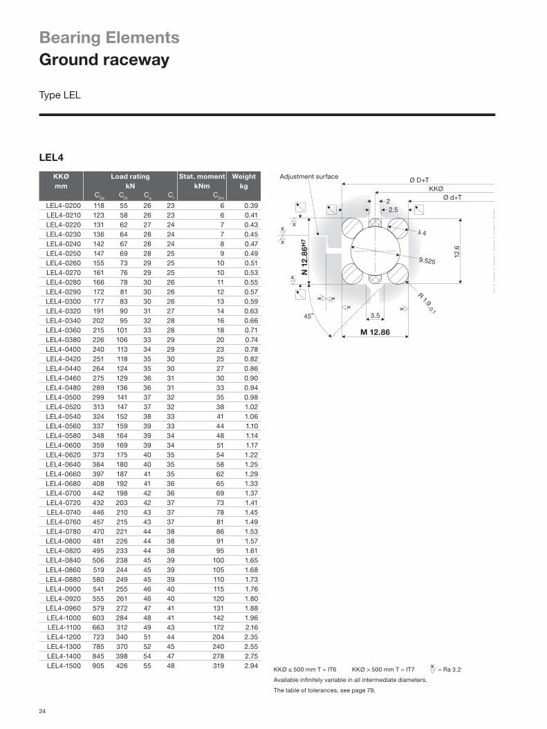
Bearing ElementsGround raceway
Type LEL
KKØ Load rating Stat. moment Weightmm kN kNm kg
C0a C0r Ca Cr C0m
LEL1.5-0070 13 6 7 6 0.2 0.04LEL1.5-0080 15 7 7 6 0.3 0.05LEL1.5-0090 18 8 8 7 0.4 0.05LEL1.5-0100 20 9 8 7 0.5 0.06LEL1.5-0110 22 10 8 7 0.6 0.07LEL1.5-0120 23 11 9 8 0.7 0.07LEL1.5-0130 25 12 9 8 0.8 0.08LEL1.5-0140 27 13 9 8 0.9 0.09LEL1.5-0150 30 14 10 8 1.0 0.09
KKØ Load rating Stat. moment Weightmm kN kNm kg
C0a C0r Ca Cr C0m
LEL2.5-0160 73 35 20 17 3 0.10LEL2.5-0170 79 37 20 17 3 0.11LEL2.5-0180 83 39 20 18 3 0.11LEL2.5-0190 88 41 21 18 4 0.12LEL2.5-0200 93 43 21 18 4 0.12LEL2.5-0210 97 46 22 19 5 0.13LEL2.5-0220 102 48 22 19 5 0.13LEL2.5-0230 106 50 22 19 6 0.14LEL2.5-0240 112 53 23 20 6 0.15LEL2.5-0250 117 55 23 20 7 0.15LEL2.5-0260 121 57 24 20 7 0.16LEL2.5-0270 126 59 24 21 8 0.16LEL2.5-0280 130 61 24 21 9 0.17LEL2.5-0290 135 64 25 21 9 0.18LEL2.5-0300 141 66 25 22 10 0.18
LEL1.5
LEL2.5
22

70 90 110 130 150
1,0
0,8
0,6
0,4
0,2
0,0
9,0
7,0
5,0
3,0
1,0
Nm Nm
KKØmm 150 200 250 300
Typ LEL1,5 Typ LEL2,5 mm
KKØmm 50 100 150 200 250 300
0,030
0,029
0,028
0,027
0,026
0,025
Bearing typeFranke bearing elements in type LEL meet high standards in terms of runnability and accuracy. Their hardened and CNC-ground raceways, along with the ideal geometric adjustment of ball and raceway radius, lend them outstanding bearing properties. Bearing elements in the LEL type permit the greatest possible freedom of bearing design. The stand-ard mounting space is between 5.9 mm and 20.9 mm. Race ring thickness of up to 20 mm and bearing sizes up to 50 mm are possible to meet special requirements.
CharacteristicsBearing elements of the LEL type consist of two inner and two outer raceways, along with a plastic cage with retained balls. The race rings are divided at one point to compensate for the temperature expansion factor. They possess compensatory properties for demanding forms of stress. LEL are generally mounted free from clearance. The preload can be defined individually to meet the specific requirement. See 'Technical information' for the adjustment methods.
Mating structureThe bearing element mounted determines the overall con-struction's load bearing capacity. Hence the mating con-struction can be made of alternative materials such as steel, aluminium or plastic. Axial and radial accuracy (see diagram below) are defined to a substantial extent by the mating components. These properties can be enhanced by boosting the accuracy of manufacture.
Please find construction examples, special forms, special accuracies and other options of individual tailoring on pages 11 – 19. Technical details
Material Ball race rings: 54SiCr6, rolling element: 100Cr6, cage: PA12
Temperature in use –30 °C to +80 °C, briefly up to +100 °C
Circumferential speed
max. 5 m/s, without seals max. 10 m/s
Lubricant grease Klüber ISOFLEX TOPAS NCA52
Lubrication schedule
See 'Technical information'.
Tolerance details See 'Technical information'.
Please find additional data on calculation, mounting and setting in 'Technical information'.
Constructive example
Rotational resistance The rotational resistance indicates the preload on the bearing assembly. It is dependent on the respective type and the race ring diameter. The values indicated in the diagram are standard values and can be aligned individually.
Radial and axial runout accuracy The running accuracies indicated in the diagram are maximum values and may be improved by restricting the tolerances.
23
M 12.86
12.6
N 1
2.8
6H7
λ 4
KKØØ D+TAdjustment surface
2
xx
x
x
x x
x x
2.5
3.545°
Ø d+T
9.525
R 1.9-0.1
KKØ ≤ 500 mm T = IT6 KKØ > 500 mm T = IT7 = Ra 3.2
Available infinitely variable in all intermediate diameters.
The table of tolerances, see page 79.
Bearing ElementsGround raceway
Type LEL
LEL4
KKØ Load rating Stat. moment Weightmm kN kNm kg
C0a C0r Ca Cr C0m
LEL4-0200 118 55 26 23 6 0.39LEL4-0210 123 58 26 23 6 0.41LEL4-0220 131 62 27 24 7 0.43LEL4-0230 136 64 28 24 7 0.45LEL4-0240 142 67 28 24 8 0.47LEL4-0250 147 69 28 25 9 0.49LEL4-0260 155 73 29 25 10 0.51LEL4-0270 161 76 29 25 10 0.53LEL4-0280 166 78 30 26 11 0.55LEL4-0290 172 81 30 26 12 0.57LEL4-0300 177 83 30 26 13 0.59LEL4-0320 191 90 31 27 14 0.63LEL4-0340 202 95 32 28 16 0.66LEL4-0360 215 101 33 28 18 0.71LEL4-0380 226 106 33 29 20 0.74LEL4-0400 240 113 34 29 23 0.78LEL4-0420 251 118 35 30 25 0.82LEL4-0440 264 124 35 30 27 0.86LEL4-0460 275 129 36 31 30 0.90LEL4-0480 289 136 36 31 33 0.94LEL4-0500 299 141 37 32 35 0.98LEL4-0520 313 147 37 32 38 1.02LEL4-0540 324 152 38 33 41 1.06LEL4-0560 337 159 39 33 44 1.10LEL4-0580 348 164 39 34 48 1.14LEL4-0600 359 169 39 34 51 1.17LEL4-0620 373 175 40 35 54 1.22LEL4-0640 384 180 40 35 58 1.25LEL4-0660 397 187 41 35 62 1.29LEL4-0680 408 192 41 36 65 1.33LEL4-0700 442 198 42 36 69 1.37LEL4-0720 432 203 42 37 73 1.41LEL4-0740 446 210 43 37 78 1.45LEL4-0760 457 215 43 37 81 1.49LEL4-0780 470 221 44 38 86 1.53LEL4-0800 481 226 44 38 91 1.57LEL4-0820 495 233 44 38 95 1.61LEL4-0840 506 238 45 39 100 1.65LEL4-0860 519 244 45 39 105 1.68LEL4-0880 580 249 45 39 110 1.73LEL4-0900 541 255 46 40 115 1.76LEL4-0920 555 261 46 40 120 1.80LEL4-0960 579 272 47 41 131 1.88LEL4-1000 603 284 48 41 142 1.96LEL4-1100 663 312 49 43 172 2.16LEL4-1200 723 340 51 44 204 2.35LEL4-1300 785 370 52 45 240 2.55LEL4-1400 845 398 54 47 278 2.75LEL4-1500 905 426 55 48 319 2.94
24

100 300 500 700 900 1100 1300 1500
180
140
120
80
40
0
Nm
KKØmm
0,10
0,08
0,06
0,04
0,02
mm
KKØmm 100 300 500 700 900 1100 1300 1500
Bearing typeFranke bearing elements in type LEL meet high standards in terms of runnability and accuracy. Their hardened and CNC-ground raceways, along with the ideal geometric adjustment of ball and raceway radius, lend them outstanding bearing properties. Bearing elements in the LEL type permit the greatest possible freedom of bearing design. The stand-ard mounting space is between 5.9 mm and 20.9 mm. Race ring thickness of up to 20 mm and bearing sizes up to 50 mm are possible to meet special requirements.
CharacteristicsBearing elements of the LEL type consist of two inner and two outer raceways, along with a plastic cage with retained balls. The race rings are divided at one point to compensate for the temperature expansion factor. They possess compensatory properties for demanding forms of stress. LEL are generally mounted free from clearance. The preload can be defined individually to meet the specific requirement. See 'Technical information' for the adjustment methods.
Mating structureThe bearing element mounted determines the overall con-struction's load bearing capacity. Hence the mating con-struction can be made of alternative materials such as steel, aluminium or plastic. Axial and radial accuracy (see diagram below) are defined to a substantial extent by the mating components. These properties can be enhanced by boosting the accuracy of manufacture.
Please find construction examples, special forms, special accuracies and other options of individual tailoring on pages 11 – 19.
Technical details
Material Ball race rings: 54SiCr6, rolling element: 100Cr6, cage: TPU
Temperature in use –30 °C to +80 °C, briefly up to +100 °C
Circumferential speed
max. 5 m/s, without seals max. 10 m/s
Lubricant grease Klüber ISOFLEX TOPAS NCA52
Lubrication schedule
See 'Technical information'.
Tolerance details See 'Technical information'.
Please find additional data on calculation, mounting and setting in 'Technical information'.
Constructive example
Rotational resistance The rotational resistance indicates the preload on the bearing assembly. It is dependent on the respective type and the race ring diameter. The values indicated in the diagram are standard values and can be aligned individually.
Radial and axial runout accuracy The running accuracies indicated in the diagram are maximum values and may be improved by restricting the tolerances.
25

M 15.5
N 1
5.5H
7
λ 5
KKØ
3.5
12
R 2.4-0.1
2
45°
17
6.2
Ø D+TAdjustment surface
Ø d+T
xx
x
x
x x
x x
KKØ ≤ 500 mm T = IT6 KKØ > 500 mm T = IT7 = Ra 3.2
Available infinitely variable in all intermediate diameters.
The table of tolerances, see page 79.
Bearing ElementsGround raceway
Type LEL
LEL5
KKØ Load rating Stat. moment Weightmm kN kNm kg
C0a C0r Ca Cr C0m
LEL5-0220 257 121 41 35 13 0.70LEL5-0230 267 126 41 36 15 0.73LEL5-0240 279 131 42 36 16 0.76LEL5-0250 289 136 43 37 17 0.79LEL5-0260 305 144 44 38 19 0.82LEL5-0270 316 149 44 38 20 0.85LEL5-0280 327 154 45 39 22 0.88LEL5-0290 337 159 45 39 23 0.91LEL5-0300 348 164 46 39 25 0.94LEL5-0320 375 176 47 41 28 1.02LEL5-0340 396 187 48 41 32 1.08LEL5-0360 423 199 49 42 36 1.14LEL5-0380 444 209 50 43 40 1.20LEL5-0400 471 222 51 44 44 1.26LEL5-0420 493 232 52 45 49 1.33LEL5-0440 519 244 53 46 54 1.40LEL5-0460 541 254 54 46 59 1.46LEL5-0480 567 267 55 47 64 1.53LEL5-0500 589 277 55 48 69 1.59LEL5-0520 616 290 56 49 75 1.66LEL5-0540 637 300 57 49 81 1.72LEL5-0560 664 312 58 50 87 1.78LEL5-0580 685 322 59 51 94 1.85LEL5-0600 707 333 59 51 100 1.91LEL5-0620 733 345 60 52 107 1.97LEL5-0640 755 355 61 53 114 2.03LEL5-0660 781 367 62 53 121 2.09LEL5-0680 803 378 62 54 128 2.16LEL5-0700 830 390 63 54 137 2.23LEL5-0720 851 400 63 55 144 2.29LEL5-0740 878 413 64 56 153 2.36LEL5-0760 899 423 65 56 161 2.43LEL5-0780 926 436 66 57 170 2.49LEL5-0800 947 446 66 57 178 2.55LEL5-0820 974 458 67 58 188 2.61LEL5-0840 995 468 67 58 197 2.67LEL5-0860 1022 484 68 59 207 2.74LEL5-0880 1044 491 68 59 216 2.80LEL5-0900 1065 501 69 60 226 2.86LEL5-0920 1092 514 70 60 236 2.92LEL5-0940 1113 524 70 61 246 2.98LEL5-0960 1140 536 71 61 257 3.04LEL5-0980 1161 546 71 62 268 3.10LEL5-1000 1188 559 72 62 280 3.19LEL5-1100 1306 614 74 64 338 3.50LEL5-1200 1423 670 77 66 402 3.82LEL5-1300 1546 728 79 68 473 4.14LEL5-1400 1664 783 81 70 548 4.46LEL5-1500 1782 839 83 72 629 4.77
26

Nm
KKØmm 100 300 500 700 900 1100 1300 1500
200
150
100
50
0
0,10
0,08
0,06
0,04
0,02
mm
KKØmm 100 300 500 700 900 1100 1300 1500
Bearing typeFranke bearing elements in type LEL meet high standards in terms of runnability and accuracy. Their hardened and CNC-ground raceways, along with the ideal geometric adjustment of ball and raceway radius, lend them outstanding bearing properties. Bearing elements in the LEL type permit the greatest possible freedom of bearing design. The stand-ard mounting space is between 5.9 mm and 20.9 mm. Race ring thickness of up to 20 mm and bearing sizes up to 50 mm are possible to meet special requirements.
CharacteristicsBearing elements of the LEL type consist of two inner and two outer raceways, along with a plastic cage with retained balls. The race rings are divided at one point to compensate for the temperature expansion factor. They possess compensatory properties for demanding forms of stress. LEL are generally mounted free from clearance. The preload can be defined individually to meet the specific requirement. See 'Technical information' for the adjustment methods.
Mating structureThe bearing element mounted determines the overall con-struction's load bearing capacity. Hence the mating con-struction can be made of alternative materials such as steel, aluminium or plastic. Axial and radial accuracy (see diagram below) are defined to a substantial extent by the mating components. These properties can be enhanced by boosting the accuracy of manufacture.
Please find construction examples, special forms, special accuracies and other options of individual tailoring on pages 11 – 19.
Technical details
Material Ball race rings: 54SiCr6, rolling element: 100Cr6, cage: TPU
Temperature in use –30 °C to +80 °C, briefly up to +100 °C
Circumferential speed
max. 5 m/s, without seals max. 10 m/s
Lubricant grease Klüber ISOFLEX TOPAS NCA52
Lubrication schedule
See 'Technical information'.
Tolerance details See 'Technical information'.
Please find additional data on calculation, mounting and setting in 'Technical information'.
Constructive example
Rotational resistance The rotational resistance indicates the preload on the bearing assembly. It is dependent on the respective type and the race ring diameter. The values indicated in the diagram are standard values and can be aligned individually.
Radial and axial runout accuracy The running accuracies indicated in the diagram are maximum values and may be improved by restricting the tolerances.
27
M 20.9
N 2
0.9H
7
λ 7
KKØØ D+TAdjustment surface
2
x
xx
x
x
xx
xx
3
19.6
16
R 3.4-0.13.5
45°
Ø d+T
KKØ ≤ 500 mm T = IT6 KKØ > 500 mm T = IT7 = Ra 3.2
Available infinitely variable in all intermediate diameters.
The table of tolerances, see page 79.
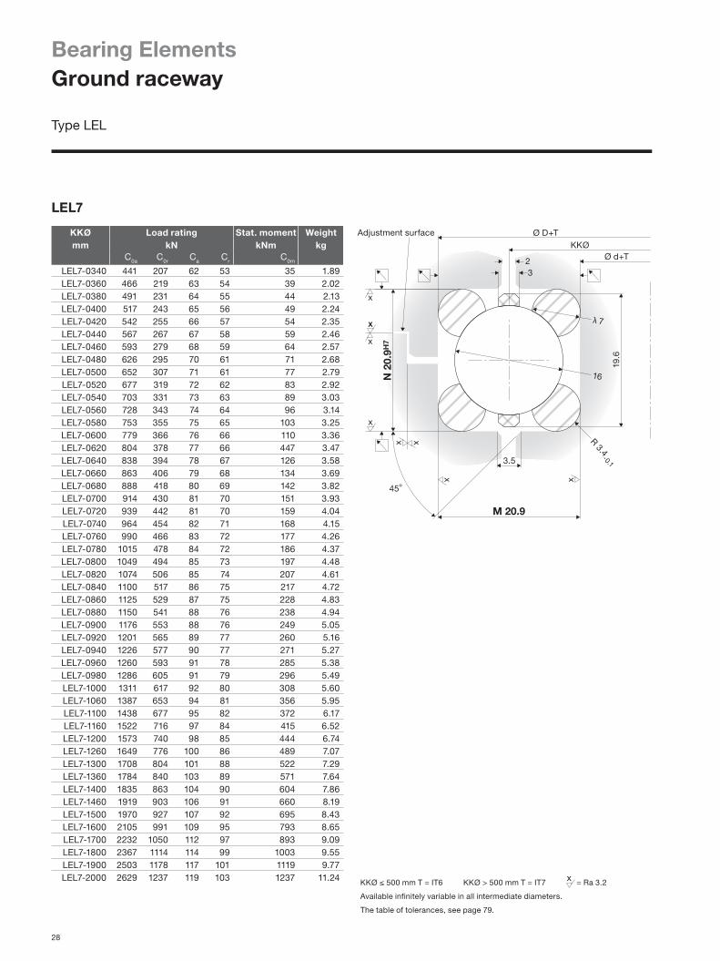
Bearing ElementsGround raceway
Type LEL
LEL7
KKØ Load rating Stat. moment Weightmm kN kNm kg
C0a C0r Ca Cr C0m
LEL7-0340 441 207 62 53 35 1.89LEL7-0360 466 219 63 54 39 2.02LEL7-0380 491 231 64 55 44 2.13LEL7-0400 517 243 65 56 49 2.24LEL7-0420 542 255 66 57 54 2.35LEL7-0440 567 267 67 58 59 2.46LEL7-0460 593 279 68 59 64 2.57LEL7-0480 626 295 70 61 71 2.68LEL7-0500 652 307 71 61 77 2.79LEL7-0520 677 319 72 62 83 2.92LEL7-0540 703 331 73 63 89 3.03LEL7-0560 728 343 74 64 96 3.14LEL7-0580 753 355 75 65 103 3.25LEL7-0600 779 366 76 66 110 3.36LEL7-0620 804 378 77 66 447 3.47LEL7-0640 838 394 78 67 126 3.58LEL7-0660 863 406 79 68 134 3.69LEL7-0680 888 418 80 69 142 3.82LEL7-0700 914 430 81 70 151 3.93LEL7-0720 939 442 81 70 159 4.04LEL7-0740 964 454 82 71 168 4.15LEL7-0760 990 466 83 72 177 4.26LEL7-0780 1015 478 84 72 186 4.37LEL7-0800 1049 494 85 73 197 4.48LEL7-0820 1074 506 85 74 207 4.61LEL7-0840 1100 517 86 75 217 4.72LEL7-0860 1125 529 87 75 228 4.83LEL7-0880 1150 541 88 76 238 4.94LEL7-0900 1176 553 88 76 249 5.05LEL7-0920 1201 565 89 77 260 5.16LEL7-0940 1226 577 90 77 271 5.27LEL7-0960 1260 593 91 78 285 5.38LEL7-0980 1286 605 91 79 296 5.49LEL7-1000 1311 617 92 80 308 5.60LEL7-1060 1387 653 94 81 356 5.95LEL7-1100 1438 677 95 82 372 6.17LEL7-1160 1522 716 97 84 415 6.52LEL7-1200 1573 740 98 85 444 6.74LEL7-1260 1649 776 100 86 489 7.07LEL7-1300 1708 804 101 88 522 7.29LEL7-1360 1784 840 103 89 571 7.64LEL7-1400 1835 863 104 90 604 7.86LEL7-1460 1919 903 106 91 660 8.19LEL7-1500 1970 927 107 92 695 8.43LEL7-1600 2105 991 109 95 793 8.65LEL7-1700 2232 1050 112 97 893 9.09LEL7-1800 2367 1114 114 99 1003 9.55LEL7-1900 2503 1178 117 101 1119 9.77LEL7-2000 2629 1237 119 103 1237 11.24
28

600
500
400
300
200
100
0
Nm
KKØmm 200 400 600 800 1000 1200 1400 1600 1800 2000
mm
KKØmm 200 400 600 800 1000 1200 1400 1600 1800 2000
0,12
0,10
0,08
0,06
0,04
0,02
Bearing typeFranke bearing elements in type LEL meet high standards in terms of runnability and accuracy. Their hardened and CNC-ground raceways, along with the ideal geometric adjustment of ball and raceway radius, lend them outstanding bearing properties. Bearing elements in the LEL type permit the greatest possible freedom of bearing design. The stand-ard mounting space is between 5.9 mm and 20.9 mm. Race ring thickness of up to 20 mm and bearing sizes up to 50 mm are possible to meet special requirements.
CharacteristicsBearing elements of the LEL type consist of two inner and two outer raceways, along with a plastic cage with retained balls. The race rings are divided at one point to compensate for the temperature expansion factor. They possess compensatory properties for demanding forms of stress. LEL are generally mounted free from clearance. The preload can be defined individually to meet the specific requirement. See 'Technical information' for the adjustment methods.
Mating structureThe bearing element mounted determines the overall con-struction's load bearing capacity. Hence the mating con-struction can be made of alternative materials such as steel, aluminium or plastic. Axial and radial accuracy (see diagram below) are defined to a substantial extent by the mating components. These properties can be enhanced by boosting the accuracy of manufacture.
Please find construction examples, special forms, special accuracies and other options of individual tailoring on pages 11 – 19.
Technical details
Material Ball race rings: 54SiCr6, rolling element: 100Cr6, cage: PA12
Temperature in use –30 °C to +80 °C, briefly up to +100 °C
Circumferential speed
max. 5 m/s, without seals max. 10 m/s
Lubricant grease Klüber ISOFLEX TOPAS NCA52
Lubrication schedule
See 'Technical information'.
Tolerance details See 'Technical information'.
Please find additional data on calculation, mounting and setting in 'Technical information'.
Constructive example
Rotational resistance The rotational resistance indicates the preload on the bearing assembly. It is dependent on the respective type and the race ring diameter. The values indicated in the diagram are standard values and can be aligned individually.
Radial and axial runout accuracy The running accuracies indicated in the diagram are maximum values and may be improved by restricting the tolerances.
29

M 11
12.6
N 1
3H7
KKØ
3.4
1.6
Ø D+TAdjustment surface
x
x
xx
2.5
3
4
Ø d+T
9.525
Rm
ax 0.3
Adjustment surface
2.25
1.4
M 7.45
N 8
.95H
7
3
1.6
3
8.6
Ø d+T
Ø D+T
Rmax 0.1
6
KKØ
x
x
x x
New
KKØ ≤ 500 mm T = IT6 KKØ > 500 mm T = IT7 = Ra 3.2
Available infinitely variable in all intermediate diameters.
The table of tolerances, see page 79.
KKØ Load rating Stat. moment Weightmm kN kNm kg
C0a C0r Ca Cr C0m
LER2-0080 28 13 10 8 1 0,07LER2-0100 34 16 10 9 1 0,08LER2-0120 41 20 11 10 1 0,10LER2-0140 49 23 12 10 2 0,12LER2-0160 56 26 13 11 2 0,13LER2-0180 64 30 13 12 3 0,15LER2-0200 70 33 14 12 3 0,17LER2-0220 77 36 14 12 4 0,19LER2-0240 85 40 15 13 5 0,20LER2-0260 92 43 15 13 6 0,22LER2-0280 99 47 16 14 7 0,24LER2-0300 106 50 16 14 7 0,25LER2-0320 113 53 16 14 9 0,27LER2-0340 121 57 17 15 10 0,29LER2-0360 128 60 17 15 11 0,30LER2-0380 135 64 18 15 12 0,32LER2-0400 142 67 18 15 13 0,34
KKØ Load rating Stat. moment Weightmm kN kNm kg
C0a C0r Ca Cr C0m
LER3-0100 54 25 18 16 1 0,17LER3-0150 82 39 22 19 3 0,25LER3-0200 110 52 24 21 5 0,35LER3-0250 138 65 26 23 8 0,44LER3-0300 166 78 28 24 12 0,52LER3-0350 196 92 30 26 16 0,61LER3-0400 224 106 32 27 21 0,68LER3-0450 252 119 33 29 27 0,79LER3-0500 280 132 34 30 33 0,87LER3-0550 308 145 36 31 40 0,96LER3-0600 336 158 37 32 47 1,05LER3-0650 366 172 38 33 56 1,14LER3-0700 394 186 39 34 65 1,23LER3-0750 422 199 40 35 75 1,31LER3-0800 450 212 41 35 85 1,40LER3-0850 478 225 42 36 42 1,49LER3-0900 506 238 43 37 107 1,57LER3-0950 537 253 44 38 120 1,67LER3-1000 565 266 44 38 132 1,75LER3-1100 621 292 46 40 161 1,93LER3-1200 676 318 47 41 191 2,10LER3-1300 735 346 49 42 225 2,28LER3-1400 791 372 50 43 260 2,45LER3-1500 847 398 52 45 299 2,63
Type LER
LER2
LER3
Bearing ElementsRectangular profile/profiled raceway
30

0 100 200 300 400
3,0
2,5
2,0
1,5
1,0
0,0
Nm Nm
KKØmm 0 500 1000 1500
Typ LER2 Typ LER3160
120
80
40
0
0,10
0,08
0,06
0,04
0,02
mm
KKØmm 0 100 300 500 700 900 1100 1300 1500
Bearing type Franke bearing elements in type LER are designed for medium rotational speeds and accuracies. They run smoothly, possess high dynamism and require just compact mounting space.The straight contact surface ensures simple integration in the mating structure and also a high rigidity. The attractive price makes this bearing element type LER an economic solution.
CharacteristicsBearing elements of the LER type consist of two inner and two outer raceways, along with a plastic cage with retained balls. The race rings are divided at one point to compensate for the temperature expansion factor. They possess compensatory properties for demanding forms of stress. LER are generally mounted free from clearance. The preload can be defined individually to meet the specific requirement. See 'Technical information' for the adjustment methods.
Mating structureThe bearing element mounted determines the overall con-struction's load bearing capacity. Hence the mating con-struction can be made of alternative materials such as steel, aluminium or plastic. Axial and radial accuracy (see diagram below) are defined to a substantial extent by the mating components. These properties can be enhanced by boosting the accuracy of manufacture.Please find construction examples, special forms, special accuracies and other options of individual tailoring on pages 11 – 19.
Technical details
Material Ball race rings: 54SiCr6, rolling element: 100Cr6, cage: PA12 / TPU
Temperature in use –30 °C to +80 °C, briefly up to +100 °C
Circumferential speed
max. 5 m/s, without seals max. 10 m/s
Lubricant grease Klüber ISOFLEX TOPAS NCA52
Lubrication schedule
See 'Technical information'.
Tolerance details See 'Technical information'.
Please find additional data on calculation, mounting and setting in 'Technical information'.
Constructive example
Rotational resistance The rotational resistance indicates the preload on the bearing assembly. It is dependent on the respective type and the race ring diameter. The values indicated in the diagram are standard values and can be aligned individually.
Radial and axial runout accuracy The running accuracies indicated in the diagram are maximum values and may be improved by restricting the tolerances.
31

4
5M 14
3.5
17
5.8
12
Adjustment surface
N 1
6H7
Rmax 0.3
Ø d+T
Ø D+TKKØ
2
x
x
x x
5
M 15.75
N 1
7.5H
7
4.4
3.52
12
17
Adjustment surface
Ø d+T
Ø D+T
Rm
ax 0.3
6
KKØ
x x
x
x
New
KKØ ≤ 500 mm T = IT6 KKØ > 500 mm T = IT7 = Ra 3.2
Available infinitely variable in all intermediate diameters.
The table of tolerances, see page 79.
Bearing ElementsRectangular profile/profiled raceway
KKØ Load rating Stat. moment Weightmm kN kNm kg
C0a C0r Ca Cr C0m
LER4-0200 174 82 44 38 8 0,61LER4-0250 219 103 48 42 13 0,76LER4-0300 264 124 52 45 19 0,91LER4-0350 312 147 55 48 26 1,07LER4-0400 357 168 58 50 34 1,22LER4-0450 401 189 60 52 42 1,37LER4-0500 446 210 63 54 52 1,57LER4-0550 490 231 65 56 63 1,67LER4-0600 535 252 67 58 75 1,89LER4-0650 583 274 69 60 89 1,99LER4-0700 628 295 71 62 103 2,14LER4-0750 672 316 73 63 119 2,29LER4-0800 717 337 75 65 135 2,45LER4-0850 761 358 76 66 152 2,60LER4-0900 806 379 78 68 171 2,75LER4-0950 855 402 80 69 191 2,90LER4-1000 899 423 81 70 212 3,05LER4-1100 988 465 84 73 256 3,36LER4-1200 1077 507 87 75 304 3,67LER4-1300 1170 551 90 77 358 3,98LER4-1400 1259 593 92 80 415 4,28LER4-1500 1348 635 94 82 476 4,59
KKØ Load rating Stat. moment Weightmm kN kNm kg
C0a C0r Ca Cr C0m
LER5-0250 260 122 48 42 15 1,33LER5-0300 313 147 52 45 22 1,52LER5-0350 371 175 55 48 31 1,71LER5-0400 424 199 58 50 40 1,90LER5-0450 477 224 60 52 50 2,09LER5-0500 530 249 63 54 62 2,29LER5-0550 583 274 65 55 66 2,48LER5-0600 635 299 67 58 90 2,67LER5-0650 693 326 69 60 106 2,85LER5-0700 746 351 71 62 123 3,05LER5-0750 799 376 73 63 141 3,24LER5-0800 852 401 75 65 160 3,43LER5-0850 905 426 76 66 181 3,62LER5-0900 958 451 78 68 203 3,81LER5-0950 1016 478 80 69 227 4,19LER5-1000 1068 503 81 70 251 4,57LER5-1100 1174 553 84 73 304 4,96LER5-1200 1280 602 87 75 361 5,34LER5-1300 1391 655 90 77 425 5,72LER5-1400 1497 704 92 80 493 6,18LER5-1500 1603 754 94 82 566 6,48LER5-1600 1713 806 97 84 645 6,87
Type LER
LER4
LER5
32

Nm
KKØmm
250
200
150
100
50
0
200 400 600 800 1000 1200 1400 1600 1800
0,10
0,08
0,06
0,04
0,02
0 200 400 600 800 1000 1200 1400 1600 1800
mm
KKØmm
Bearing type Franke bearing elements in type LER are designed for medium rotational speeds and accuracies. They run smoothly, possess high dynamism and require just compact mounting space.The straight contact surface ensures simple integration in the mating structure and also a high rigidity. The attractive price makes this bearing element type LER an economic solution.
CharacteristicsBearing elements of the LER type consist of two inner and two outer raceways, along with a plastic cage with retained balls. The race rings are divided at one point to compensate for the temperature expansion factor. They possess compensatory properties for demanding forms of stress. LER are generally mounted free from clearance. The preload can be defined individually to meet the specific requirement. See 'Technical information' for the adjustment methods.
Mating structureThe bearing element mounted determines the overall con-struction's load bearing capacity. Hence the mating con-struction can be made of alternative materials such as steel, aluminium or plastic. Axial and radial accuracy (see diagram below) are defined to a substantial extent by the mating components. These properties can be enhanced by boosting the accuracy of manufacture.Please find construction examples, special forms, special accuracies and other options of individual tailoring on pages 11 – 19.
Technical details
Material Ball race rings: 54SiCr6, rolling element: 100Cr6, cage: TPU
Temperature in use –30 °C to +80 °C, briefly up to +100 °C
Circumferential speed
max. 5 m/s, without seals max. 10 m/s
Lubricant grease Klüber ISOFLEX TOPAS NCA52
Lubrication schedule
See 'Technical information'.
Tolerance details See 'Technical information'.
Please find additional data on calculation, mounting and setting in 'Technical information'.
Constructive example
Rotational resistance The rotational resistance indicates the preload on the bearing assembly. It is dependent on the respective type and the race ring diameter. The values indicated in the diagram are standard values and can be aligned individually.
Radial and axial runout accuracy The running accuracies indicated in the diagram are maximum values and may be improved by restricting the tolerances.
33

34
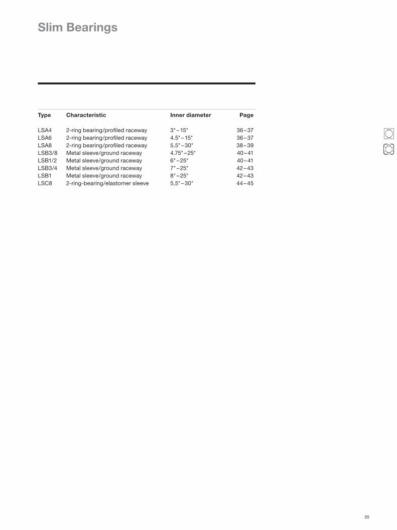
Slim Bearings
Type Characteristic Inner diameter Page
LSA4 2-ring bearing/profiled raceway 3" – 15" 36 – 37LSA6 2-ring bearing/profiled raceway 4.5" – 15" 36 – 37LSA8 2-ring bearing/profiled raceway 5.5" – 30" 38 – 39LSB3/8 Metal sleeve/ground raceway 4.75" – 25" 40 – 41LSB1/2 Metal sleeve/ground raceway 6" – 25" 40 – 41LSB3/4 Metal sleeve/ground raceway 7" – 25" 42 – 43LSB1 Metal sleeve/ground raceway 8" – 25" 42 – 43LSC8 2-ring-bearing/elastomer sleeve 5,5" – 30" 44 – 45
35

Ø D+TKKØ
Ø d-T
1.3
N 4
H7
4M9
M 7
2
Adjustment surface
Rm
ax 0.2x x
xx
6.3 4
1.3
Ø d-T
2.0
Ø D+T
x
x
x x
M 6.35
N 6
.35H
7
KKØ
6.35
-0.0
1 -0
.05
Rm
ax 0,2
4
KKØ ≤ 250 mm T = IT7 KKØ > 250 mm T = IT6 = Ra 3.2
Available infinitely variable in all intermediate diameters.
The table of tolerances, see page 79.
Slim Bearings2-ring bearing/profiled raceway
Type LSA
LSA4
LSA6
d Dimensions Load rating Stat. moment
Weight
Inch mm kN kNmD d C0a C0r Ca Cr C0m
LSA4-3 90.20 76.20 20 9 5 5 0.4 0.04LSA4-3.5 102.90 88.90 23 11 6 5 0.5 0.05LSA4-4 115.60 101.60 26 12 6 5 0.7 0.05LSA4-4.5 128.30 114.30 29 14 6 5 0.8 0.06LSA4-5 141.00 127.00 33 15 7 6 1.0 0.07LSA4-5.5 153.70 139.70 36 17 7 6 1.0 0.07LSA4-6 166.40 152.40 38 18 7 6 1.0 0.08LSA4-6.5 179.10 165.10 42 20 7 6 2.0 0.08LSA4-7 191.80 177.80 45 21 7 6 2.0 0.09LSA4-7.5 204.50 190.50 48 23 8 7 2.0 0.10LSA4-8 217.20 203.20 51 24 8 7 3.0 0.10LSA4-8.5 229.90 215.90 54 26 8 7 3.0 0.11LSA4-9 242.60 228.60 58 27 8 7 3.0 0.12LSA4-9.5 255.30 241.30 60 28 8 7 4.0 0.12LSA4-10 268.00 254.00 64 30 8 7 4.0 0.13LSA4-11 293.40 279.40 70 33 9 7 5.0 0.14LSA4-12 318.80 304.80 76 36 9 8 6.0 0.15LSA4-13 344.20 330.20 82 39 9 8 7.0 0.17LSA4-14 369.60 355.60 89 42 9 8 8.0 0.18LSA4-15 395.00 381.00 95 45 10 8 9.0 0.19
d Dimensions Load rating Stat. moment
Weight
Inch mm kN kNmD d C0a C0r Ca Cr C0m
LSA6-4.5 127.00 114.30 41 19 6 5 1 0.08LSA6-5 139.70 127.00 44 21 6 6 1 0.09LSA6-5.5 152.40 139.70 49 23 7 6 2 0.10LSA6-6 165.10 152.40 53 25 7 6 2 0.11LSA6-6.5 177.80 165.10 58 27 7 6 2 0.12LSA6-7 190.50 177.80 62 29 7 6 3 0.13LSA6-7.5 203.20 190.50 67 31 8 7 3 0.14LSA6-8 215.90 203.20 70 33 8 7 3 0.15LSA6-8.5 228.60 215.90 75 35 8 7 4 0.16LSA6-9 241.30 228.60 79 37 8 7 4 0.16LSA6-9.5 254.00 241.30 84 39 8 7 5 0.17LSA6-10 266.70 254.00 88 41 8 7 5 0.18LSA6-11 292.10 279.40 97 46 9 7 7 0.20LSA6-12 317.50 304.80 105 49 9 8 8 0.22LSA6-13 342.90 330.20 114 54 9 8 9 0.24LSA6-14 368.30 355.60 123 58 9 8 10 0.25LSA6-15 393.70 381.00 131 62 10 8 12 0.27
New
New
36

dInch
Nm3.0
2.5
2.0
1.5
1.0
3 5 7 9 11 13 15
0.15
0.13
0.11
0.09
0.07
mm
dInch 3 5 7 9 11 13 15
Bearing type Franke slim bearings of type LSA deliver a convincingly smooth run, require extremely compact mounting space, ensure simple assembly and come at a favorable price.
Characteristics Slim bearings type LSA consist of one inner and one outer race ring with hardened and profiled raceway and a plastic cage with retained balls. The rolling elements touch the race rings at two points each, hence ensuring the 4-point system. The race rings are separated; their diameter can therefore be altered elastically for mounting.
Mating structureThe bearing element mounted determines the overall con-struction's load bearing capacity. Hence the mating con-struction can be made of alternative materials such as steel, aluminium or plastic. Axial and radial accuracy (see diagram below) are defined to a substantial extent by the mating components. These properties can be enhanced by boosting the accuracy of manufacture.Please find construction examples, special forms, special accuracies and other options of individual tailoring on pages 11 – 19.
Technical details
Material Ball race rings: 54SiCr6, rolling element: 100Cr6, cage: PA12
Temperature in use –30 °C to +80 °C, briefly up to +100 °C
Circumferential speed
max. 5 m/s, without seals max. 10 m/s
Lubricant grease Klüber ISOFLEX TOPAS NCA52
Lubrication schedule
See 'Technical information'.
Tolerance details See 'Technical information'.
Please find additional data on calculation, mounting and setting in 'Technical information'.
Constructive example
Rotational resistance The rotational resistance indicates the preload on the bearing assembly. It is dependent on the respective type and the race ring diameter. The values indicated in the diagram are standard values and can be aligned individually.
Radial and axial runout accuracy The running accuracies indicated in the diagram are maximum values and may be improved by restricting the tolerances.
37

1.5
3
Ø d-T
5
1.9
Ø D+T
x
x
x x
7.94
-0.0
1 -0
.05
M 7.94
N 7
.94H
7
KKØ
Rm
ax 0,2
KKØ ≤ 250 mm T = IT7 KKØ > 250 mm T = IT6 = Ra 3.2
Available infinitely variable in all intermediate diameters.
The table of tolerances, see page 79.
Slim Bearings2-ring bearing/profiled raceway
Type LSA
LSA8
d Dimensions Load rating Stat. moment
Weight
Inch mm kN kNmD d C0a C0r Ca Cr C0m
LSA8-5.5 155.58 139.70 55 26 10 9 2 0.13LSA8-6 168.28 152.40 59 28 10 9 2 0.14LSA8-6.5 180.98 165.10 65 30 11 9 3 0.16LSA8-7 193.68 177.80 69 33 11 9 3 0.17LSA8-7.5 206.38 190.50 76 36 11 10 4 0.18LSA8-8 219.08 203.20 79 37 11 10 4 0.19LSA8-8.5 231.78 215.90 84 39 12 10 4 0.20LSA8-9 244.48 228.60 88 42 12 10 5 0.21LSA8-9.5 257.18 241.30 93 44 12 10 5 0.22LSA8-10 269.88 254.00 98 46 12 11 6 0.24LSA8-11 295.28 279.40 107 50 13 11 7 0.26LSA8-12 320.68 304.80 117 55 13 11 9 0.28LSA8-13 346.08 330.20 126 59 13 12 10 0.30LSA8-14 371.48 355.60 136 64 14 12 12 0.33LSA8-15 396.88 381.00 146 69 14 12 13 0.35LSA8-16 422.28 406.40 155 73 15 13 15 0.37LSA8-17 447.68 431.80 165 78 15 13 17 0.39LSA8-18 473.08 457.20 174 82 15 13 19 0.42LSA8-19 498.48 482.60 184 87 15 13 21 0.44LSA8-20 523.88 508.00 194 91 16 14 24 0.47LSA8-22 574.68 558.80 213 100 16 14 28 0.52LSA8-24 625.48 609.60 232 109 17 15 34 0.56LSA8-26 676.28 660.40 253 119 17 15 40 0.61LSA8-28 727.08 711.20 270 127 18 15 46 0.66LSA8-30 777.88 762.00 294 138 18 16 54 0.71
38

6.0
5.0
4.0
3.0
2.0
1.0
0.0d
Inch
Nm
4 8 12 22 24 26 28 32
0.11
0.10
0.09
0.08
0.07
mm
dInch 4 8 12 22 24 26 28 32
Bearing type Franke slim bearings of type LSA deliver a convincingly smooth run, require extremely compact mounting space, ensure simple assembly and come at a favorable price.
Characteristics Slim bearings type LSA consist of one inner and one outer race ring with hardened and profiled raceway and a plastic cage with retained balls. The rolling elements touch the race rings at two points each, hence ensuring the 4-point system. The race rings are separated; their diameter can therefore be altered elastically for mounting.
Mating structureThe bearing element mounted determines the overall con-struction's load bearing capacity. Hence the mating con-struction can be made of alternative materials such as steel, aluminium or plastic. Axial and radial accuracy (see diagram below) are defined to a substantial extent by the mating components. These properties can be enhanced by boosting the accuracy of manufacture.Please find construction examples, special forms, special accuracies and other options of individual tailoring on pages 11 – 19.
Technical details
Material Ball race rings: 54SiCr6, rolling element: 100Cr6, cage: PA12
Temperature in use –30 °C to +80 °C, briefly up to +100 °C
Circumferential speed
max. 5 m/s, without seals max. 10 m/s
Lubricant grease Klüber ISOFLEX TOPAS NCA52
Lubrication schedule
See 'Technical information'.
Tolerance details See 'Technical information'.
Please find additional data on calculation, mounting and setting in 'Technical information'.
Constructive example
Rotational resistance The rotational resistance indicates the preload on the bearing assembly. It is dependent on the respective type and the race ring diameter. The values indicated in the diagram are standard values and can be aligned individually.
Radial and axial runout accuracy The running accuracies indicated in the diagram are maximum values and may be improved by restricting the tolerances.
39

M 9.525
N 9
.57
–0.0
2
KKØ
Ø DH7
Ø d+7
Ø D-7
x
x
x x
Ø dg6
6
N 1
2.7
6 –0
.03
M 12.7
KKØ
Ø DH7
Ø d+9.4
Ø D-9.4
x
x
x x
Ø dg6
8
= Ra 3.2
Slim BearingsMetal sleeve/ground raceway
Type LSB
LSB3/8
LSB1/2
d Dimensions Load rating Stat. moment
Weight
Inch mm kN kNmD d C0a C0r Ca Cr C0m
LSB1/2-6 177.80 152.40 71 33 19 16 3 0,34LSB1/2-6.5 190.50 165.10 76 36 19 16 3 0,36LSB1/2-7 203.20 177.80 81 38 19 17 4 0,39LSB1/2-7.5 215.90 190.50 87 41 20 17 4 0,42LSB1/2-8 228.60 203.20 92 43 20 18 5 0,45LSB1/2-9 254.00 228.60 102 48 21 18 6 0,50LSB1/2-10 279.40 254.00 114 54 22 19 7 0,56LSB1/2-11 304.80 279.40 126 59 23 20 9 0,61LSB1/2-12 330.20 304.80 136 64 24 20 10 0,66LSB1/2-14 381.00 355.60 159 75 25 22 14 0,77LSB1/2-16 431.80 406.40 181 85 26 23 18 0,88LSB1/2-18 482.60 457.20 202 95 27 24 22 0,99LSB1/2-20 533.40 508.00 224 105 28 25 27 1,09LSB1/2-25 660.40 635.00 279 131 31 27 43 1,36
d Dimensions Load rating Stat. moment
Weight
Inch mm kN kNmD d C0a C0r Ca Cr C0m
LSB3/8-4.75 139.70 120.65 50 23 11 10 2 0,15LSB3/8-5 146.05 127.00 52 24 11 10 2 0,16LSB3/8-5.5 158.75 139.70 57 27 12 10 2 0,16LSB3/8-6 171.45 152.40 62 29 12 10 2 0,19LSB3/8-6.5 184.15 165.10 67 32 12 11 3 0,21LSB3/8-7 196.85 177.80 72 34 13 11 3 0,22LSB3/8-7.5 209.55 190.50 76 36 13 11 4 0,24LSB3/8-8 222.25 203.20 82 39 13 12 4 0,25LSB3/8-9 247.65 228.60 91 43 14 12 5 0,29LSB3/8-10 273.05 254.00 101 48 14 12 6 0,32LSB3/8-11 298.45 279.40 112 53 15 13 8 0,35LSB3/8-12 323.85 304.80 121 57 15 13 9 0,38LSB3/8-14 374.65 355.60 142 67 16 14 12 0,44LSB3/8-16 425.45 406.40 161 76 17 15 16 0,50LSB3/8-18 476.25 457.20 181 85 18 15 20 0,56LSB3/8-20 527.05 508.00 200 94 18 16 24 0,63LSB3/8-25 654.05 635.00 251 118 20 17 38 0,78
40

Nm NmType LSB3/8 Type LSB1/2
5 10 15 20 25 0 5 10 15 20 25d
Inch
20
15
10
5
0
12
10
8
6
4
2
0
4 8 12 16 20 24 28
mm
dInch
0.07
0.06
0.05
0.04
Bearing type Franke slim bearings of type LSB consist of a bearing element type LEL with a ground raceway, embedded in two bearing sleeves made of metal. The sleeve holds the bearing together and hence permits rapid and simple assembly.
Characteristics Slim bearings type LSB consist of two inner and outer race rings with ground raceway, one plastic cage with retained balls and a surrounding metal sleeve. The sleeves and the race rings are separated; their diameter can therefore be altered elastically for mounting. Unlike standard slim bearings, Franke slim bearings type LSB can be modified in terms of clearance/preload.
Mating structure The greatest levels of accuracy are achieved if the construc-tive design of the mating parts takes place in such a way that the handling of all diameters and surfaces relating to each other can take place within in one setting. The running accuracies indicated in the diagram are average values and may be improved by restricting the tolerances (see 'Technical information').
Please find construction examples, special forms, special accuracies and other options of individual tailoring to your applications and also instructions on assembly on pages 11 – 19.
Technical details
Material Ball race rings: 54SiCr6, rolling element: 100Cr6, cage: PA12
Temperature in use –30 °C to +80 °C, briefly up to +100 °C
Circumferential speed
max. 5 m/s, without seals max. 10 m/s
Lubricant grease Klüber ISOFLEX TOPAS NCA52
Lubrication schedule
See 'Technical information'.
Tolerance details See 'Technical information'.
Please find additional data on calculation, mounting and setting in 'Technical information'.
Constructive example
Rotational resistance The rotational resistance indicates the preload on the bearing assembly. It is dependent on the respective type and the race ring diameter. The values indicated in the diagram are standard values and can be aligned individually.
Radial and axial runout accuracy The running accuracies indicated in the diagram are maximum values and may be improved by restricting the tolerances.
41

N 1
9.12
–0.
03
M 19.05
KKØ
Ø DH7
Ø d+14
Ø D-14
x
xx x
Ø dg6
15
N 2
5.48
–0.
03
M 25.4
KKØ
Ø DH7
Ø d+18.8
Ø D-18.8
x
x
x
x
Ø dg6
20
= Ra 3.2
Slim BearingsMetal sleeve/ground raceway
Type LSB
LSB3/4
LSB1
d Dimensions Load rating Stat. moment Inch mm kN kNm
D d C0a C0r Ca Cr C0m
LSB3/4-7 215.90 177.80 153 72 49 43 7LSB3/4-7.5 228.60 190.50 167 79 51 44 8LSB3/4-8 241.30 203.20 177 83 53 45 9LSB3/4-9 266.70 228.60 197 93 55 48 11LSB3/4-10 292.10 254.00 217 102 56 49 14LSB3/4-11 317.50 279.40 241 113 59 51 17LSB3/4-12 342.90 304.80 261 123 61 53 20LSB3/4-14 393.70 355.60 300 141 64 55 26LSB3/4-16 444.50 406.40 344 162 67 58 34LSB3/4-18 495.30 457.20 388 183 71 61 43LSB3/4-20 546.10 508.00 427 201 73 63 53LSB3/4-25 673.10 635.00 530 250 79 68 82
d Dimensions Load rating Stat. moment Inch mm kN kNm
D d C0a C0r Ca Cr C0m
LSB1-8 254.00 203.20 272 128 78 68 15LSB1-9 279.40 228.60 303 142 82 71 18LSB1-10 304.80 254.00 334 157 85 73 22LSB1-11 330.20 279.40 365 172 88 76 26LSB1-12 355.60 304.80 396 186 71 78 31LSB1-14 406.40 355.60 458 216 96 83 41LSB1-16 457.20 406.40 520 245 100 87 53LSB1-18 508.00 457.20 582 274 105 91 66LSB1-20 558.80 508.00 655 308 110 95 82LSB1-25 685.80 635.00 810 381 119 103 126
42

4 8 12 16 20 24 28
mm
dInch
0.07
0.06
0.05
0.04
Nm NmType LSB3/4 Type LSB1
5 10 15 20 25 5 10 15 20 25d
Inch
50
40
30
20
10
70
60
50
40
30
20
10
Bearing type Franke slim bearings of type LSB consist of a bearing element type LEL with a ground raceway, embedded in two bearing sleeves made of metal. The sleeve holds the bearing together and hence permits rapid and simple assembly.
Characteristics Slim bearings type LSB consist of two inner and outer race rings with ground raceway, one plastic cage with retained balls and a surrounding metal sleeve. The sleeves and the race rings are separated; their diameter can therefore be altered elastically for mounting. Unlike standard slim bearings, Franke slim bearings type LSB can be modified in terms of clearance/preload.
Mating structure The greatest levels of accuracy are achieved if the construc-tive design of the mating parts takes place in such a way that the handling of all diameters and surfaces relating to each other can take place within in one setting. The running accuracies indicated in the diagram are average values and may be improved by restricting the tolerances (see 'Technical information').
Please find construction examples, special forms, special accuracies and other options of individual tailoring to your applications and also instructions on assembly on pages 11 – 19.
Technical details
Material Ball race rings: 54SiCr6, rolling element: 100Cr6, cage: PA12
Temperature in use –30 °C to +80 °C, briefly up to +100 °C
Circumferential speed
max. 5 m/s, without seals max. 10 m/s
Lubricant grease Klüber ISOFLEX TOPAS NCA52
Lubrication schedule
See 'Technical information'.
Tolerance details See 'Technical information'.
Please find additional data on calculation, mounting and setting in 'Technical information'.
Constructive example
Rotational resistance The rotational resistance indicates the preload on the bearing assembly. It is dependent on the respective type and the race ring diameter. The values indicated in the diagram are standard values and can be aligned individually.
Radial and axial runout accuracy The running accuracies indicated in the diagram are maximum values and may be improved by restricting the tolerances.
43

5
M 11,17R1 (m
ax.)
Ød
Ød (LSA8)
KKØ
ØD
N 1
0,74
–0,
01
5
R1 (max.)
Ød
Ød (LSA8)
KKØ
ØD
M 11,17
N 1
0,74
–0,
01
Slim Bearings2-ring-bearing/profiled raceway/elastomer sleeve
Type LSC
LSC8
d Dimensions Load rating Stat. moment
Weight
Inch mm kN kNmD d C0a C0r Ca Cr C0m
LSC8-5,5 158,81 136,47 55 26 10 9 2 0,16LSC8-6 171,51 149,17 59 28 10 9 2 0,17LSC8-6,5 184,21 161,87 65 30 11 9 3 0,19LSC8-7 196,91 174,57 69 33 11 9 3 0,20LSC8-7,5 209,61 187,27 76 36 11 10 4 0,21LSC8-8 222,31 199,97 79 37 11 10 4 0,23LSC8-8,5 235,01 212,67 84 39 12 10 4 0,24LSC8-9 247,71 225,37 88 42 12 10 5 0,25LSC8-9,5 260,41 238,07 93 44 12 10 5 0,26LSC8-10 273,11 250,77 98 46 12 11 6 0,28LSC8-11 298,51 276,17 107 50 13 11 7 0,31LSC8-12 323,91 301,57 117 55 13 11 9 0,33LSC8-13 349,31 326,97 126 59 13 12 10 0,36LSC8-14 374,71 352,37 136 64 14 12 12 0,39LSC8-15 400,11 377,77 146 69 14 12 13 0,42LSC8-16 425,51 403,17 155 73 15 13 15 0,44LSC8-17 450,91 428,57 165 78 15 13 17 0,46LSC8-18 476,31 453,97 174 82 15 13 19 0,50LSC8-19 501,71 479,37 184 87 15 13 21 0,52LSC8-20 527,11 504,77 194 91 16 14 24 0,56LSC8-22 577,91 555,57 213 100 16 14 28 0,62LSC8-24 628,71 606,37 232 109 17 15 34 0,66LSC8-26 679,51 657,17 253 119 17 15 40 0,72LSC8-28 730,31 707,97 270 127 18 15 46 0,78LSC8-30 781,11 758,77 294 138 18 16 54 0,84
New
Tolerance up to D=400: ± 0,05. from D>400: ± 0,07 = Ra 3,2
Tolerance up to d=400: ± 0,05. from d>400: ± 0,07
Available infinitely variable in all intermediate diameters.
44

6.0
5.0
4.0
3.0
2.0
1.0
0.0d
Inch
Nm
4 8 12 22 24 26 28 32
0.11
0.10
0.09
0.08
0.07
mm
dInch 4 8 12 22 24 26 28 32
Bearing type Franke slim bearings type LSC are characterized by silent, clearance-free running behaviour, extremely compact mounting space, easy installation and low cost.
Characteristics Slim bearings type LSC consist of an inner and outer race ring with a hardened and profiled raceway and a plastic cage with retained balls. They are covered by elastomer profiles, which take over the sealing, tolerance compensation and vibration elimination of the bearing. The balls have contact at two points at each race ring, whereby the 4-point system is maintained. The race rings are divided and can be elastically changed in diameter for installation. Due to the overlapping lips of the elastomer sleeves further sealing of the bearing is not necessary.
Mating structureThe bearing element mounted determines the overall con-struction's load bearing capacity. Hence the mating con-struction can be made of alternative materials such as steel, aluminium or plastic. Axial and radial accuracy (see diagram below) are defined to a substantial extent by the mating components. These properties can be enhanced by boosting the accuracy of manufacture.Please find construction examples, special forms, special accuracies and other options of individual tailoring on pages 11 – 19.
Technical details
Material Ball race rings: 54SiCr6, rolling element: 100Cr6, cage: PA12, elastomer:NBR
Temperature in use –30 °C to +80 °C, briefly up to +100 °C
Circumferential speed
max. 5 m/s, without seals max. 10 m/s
Lubricant grease Klüber ISOFLEX TOPAS NCA52
Lubrication schedule
See 'Technical information'.
Tolerance details See 'Technical information'.
Please find additional data on calculation, mounting and setting in 'Technical information'.
Constructive example
Rotational resistance The rotational resistance indicates the preload on the bearing assembly. It is dependent on the respective type and the race ring diameter. The values indicated in the diagram are standard values and can be aligned individually.
Radial and axial runout accuracy The running accuracies indicated in the diagram are maximum values and may be improved by restricting the tolerances.
45

46

Bearing Assemblies
Type Characteristic KKØ Page
LVA Steel design 100 – 1800 48 – 49LVB Aluminium design 100 – 1800 50 – 51LVC Angular contact ball bearing/steel design 100 – 1800 52 – 53LVD Steel design/external gear type 100 – 1800 54 – 55LVE Aluminium design/toothed belt gear type 100 – 1800 56 – 57
47

Ø DA
A
AGrease nipple DIN 3405D1-M6 up to KKØ 250 mmD1-M8 from KKØ 300 mm
A
A
TH
1H
S
H1
T1
MØ D1
10
10
Ø Di
Ø Da
Ø Dah8
Ø LiØ KK
Ø La
Ø DiH8
Bearing Assemblies Steel design
Type LVA
KKØ Dimensionsmm
D1 D H H1 M S T T1100 – 250 11 6.6 34+/-0,4 27 M 6 16,5 6,8 10300 – 350 15 9.0 38+/-0,4 31 M 8 17,5 9,0 15400 – 450 18 11.0 44+/-0,5 37 M 10 19,5 11,0 15500 – 600 20 14.0 49+/-0,5 42 M 12 20,5 13,0 20
700 – 1000 20 14.0 53+/-0,5 45 M 12 21,5 13,0 201200 – 1400 26 18.0 60+/-0,5 52 M 16 33,5 17,5 251600 – 1800 26 18.0 90+/-0,5 82 M 16 48,5 17,5 25
KKØ Dimensions Fixing/mounting
Load rating Stat. moment Weight Availability
mm per ring kN kNm kgDah8 DiH8 La Li C0a C0r Ca Cr C0m
LVA0100 150 50 135 65 6x 54 25 18 16 1 3.0 from storesLVA0150 200 100 185 115 6x 82 39 22 19 3 4.6 from storesLVA0200 250 150 235 165 8x 110 52 24 21 5 6.1 from storesLVA0250 300 200 285 215 10x 138 65 26 23 8 7.6 from storesLVA0300 360 240 340 260 12x 166 78 28 24 12 12.8 from storesLVA0350 410 290 390 310 14x 196 92 30 26 16 15.0LVA0400 470 330 445 355 14x 424 199 54 47 40 23.7 from storesLVA0450 520 380 495 405 14x 477 224 57 49 57 26.7LVA0500 580 420 550 450 14x 530 249 59 51 62 39.1 from storesLVA0600 680 520 650 550 16x 635 299 63 54 63 46.9 from storesLVA0700 790 610 750 650 22x 746 351 67 58 123 66.5LVA0800 890 710 850 750 24x 852 401 70 61 160 76.0LVA0900 990 810 950 850 24x 958 451 73 63 203 85.6LVA1000 1090 910 1050 950 26x 1068 503 76 66 251 95.0LVA1200 1300 1100 1265 1135 30x 1573 740 98 85 444 114.8LVA1400 1500 1300 1465 1335 36x 1835 864 104 90 604 169.0LVA1600 1730 1470 1685 1515 42x 2105 991 109 95 793 399.0LVA1800 1930 1670 1885 1715 46x 2367 1114 114 99 1003 449.0
48

mm0.25
0.20
0.15
0.10
0.05
0.00KKØmm 0 200 400 600 800 1000 1200 1400 1600 1800 100 200 400 600 800 1000 1200 1400 1600 1800
40
20
15
10
5
0
Nm Nm800
600
400
200
0KKØmm
Bearing type LVA is a bearing assembly with housing rings made of steel and integrated bearing element. Franke bearing assemblies in type LVA are designed for medium rotational speeds and accuracies. They are available on short notice, in some cases even from the warehouse (see table).
Characteristics Franke bearing assemblies type LVA are ready-to-use, complete bearings with integrated Wire Race Bearings. Designed as 4-point bearings, they absorb equal load from all sides and are insensitive to impact and vibration. The bearing assemblies are sealed on both sides and set free from clearance and are preloaded. On request you can receive the bearing assemblies ex works with your specified preload values.
Please find construction examples, special accuracies and other options of individual tailoring on pages 11 – 19.
Technical details
Material Inner/outer ring: C45N, ball race rings: 54SiCr6, rolling element: 100Cr6, cage: PA12, seal: NBR
Temperature in use –30 °C to +80 °C, briefly up to +100 °C
Circumferential speed
max. 5 m/s, without seals max. 10 m/s
Screw connection See 'Technical information'.
Lubricant grease Klüber ISOFLEX TOPAS NCA52
Relubrication using grease nipples according to DIN 3405
Lubrication schedule
See 'Technical information'.
Technical information/calculationPlease find additional information on bearing selection, calculation, mounting and setting in 'Technical information'. Our technical consultants are pleased to assist you in identifying the correct bearing assembly for your application.
Please call us under: +49 7361 920-0 or send us an email at: [email protected].
Rotational resistance The rotational resistance indicates the preload on the bearing assembly. It is dependent on the respective type and the race ring diameter. The values indicated in the diagram are standard values and can be aligned individually.
Radial and axial runout accuracy The running accuracies in the diagram are maximum values.
49

Ø DA
A
AGrease nipple DIN 3405D1-M6 up to KKØ 250 mmD1-M8 from KKØ 300 mm
A
A
TH
1H
H1
T1
MØ D1
10
10
Ø Di
Ø Da
Ø Dah8
Ø LiØ KK
Ø La
Ø DiH8
S
Bearing Assemblies Aluminium design
Type LVB
KKØ Dimensionsmm
D1 D H H1 M S T T1100 – 250 11 6.6 34+/-0,4 27 M 6 16,5 6,8 10300 – 350 15 9.0 38+/-0,4 31 M 8 17,5 9,0 15400 – 450 18 11.0 44+/-0,5 37 M 10 19,5 11,0 15500 – 600 20 14.0 49+/-0,5 42 M 12 20,5 13,0 20
700 – 1000 20 14.0 53+/-0,5 45 M 12 21,5 13,0 201200 – 1400 26 18.0 60+/-0,5 52 M 16 33,5 17,5 251600 – 1800 26 18.0 90+/-0,5 82 M 16 48,5 17,5 25
KKØ Dimensions Fixing/mounting
Load rating Stat. moment Weight Availability
mm per ring kN kNm kgDah8 DiH8 La Li C0a C0r Ca Cr C0m
LVB0100 150 50 135 65 6x 54 25 18 16 1 1.2 from storesLVB0150 200 100 185 115 6x 82 39 22 19 3 1.8LVB0200 250 150 235 165 8x 110 52 24 21 5 2.4 from storesLVB0250 300 200 285 215 10x 138 65 26 23 8 3.0LVB0300 360 240 340 260 12x 166 78 28 24 12 4.9 from storesLVB0350 410 290 390 310 14x 196 92 30 26 16 5.8LVB0400 470 330 445 355 14x 424 199 54 47 40 9.5LVB0450 520 380 495 405 14x 477 224 57 49 57 10.6LVB0500 580 420 550 450 14x 530 249 59 51 62 15.1LVB0600 680 520 650 550 16x 635 299 63 54 63 18.2LVB0700 790 610 750 650 22x 746 351 67 58 123 25.5LVB0800 890 710 850 750 24x 852 401 70 61 160 29.1LVB0900 990 810 950 850 24x 958 451 73 63 203 32.8LVB1000 1090 910 1050 950 26x 1068 503 76 66 251 36.4LVB1200 1300 1100 1265 1135 30x 1573 740 98 85 444 56.0LVB1400 1500 1300 1465 1335 36x 1835 864 104 90 604 65.3LVB1600 1730 1470 1685 1515 42x 2105 991 109 95 793 148.2LVB1800 1930 1670 1885 1715 46x 2367 1114 114 99 1003 166.7
50

100 200 400 600 800 1000 1200 1400 1600 1800
25
20
15
10
5
0
Nm Nm800
600
400
200
0KKØmm
mm0,30
0,20
0,15
0,10
0,05
0,00KKØmm 0 200 400 600 800 1000 1200 1400 1600 1800
Bearing type LVB is a bearing assembly with housing rings made of aluminium and integrated bearing element. Franke bearing assemblies in type LVB are designed for medium rotational speeds and accuracies. They are available on short notice, in some cases even from the warehouse (see table).
Characteristics Franke bearing assemblies type LVB are ready-to-use, complete bearings with integrated Wire Race Bearings. Designed as 4-point bearings, they absorb equal load from all sides and are insensitive to impact and vibration. The bearing assemblies are sealed on both sides and set free from clearance and are preloaded. On request you can receive the bearing assemblies ex works with your specified preload values.
Please find construction examples, special accuracies and other options of individual tailoring on pages 11 – 19.
Technical details
Material Inner/outer ring: AlZnMgCu05, ball race rings: 54SiCr6, rolling element: 100Cr6, cage: PA12, seal: NBR
Temperature in use –30 °C to +80 °C, briefly up to +100 °C
Circumferential speed
max. 5 m/s, without seals max. 10 m/s
Screw connection See 'Technical information' on p. XY
Lubricant grease Klüber ISOFLEX TOPAS NCA52
Relubrication using grease nipples according to DIN 3405
Lubrication schedule
See 'Technical information'.
Technical information/calculationPlease find additional information on bearing selection, calculation, mounting and setting in 'Technical information'. Our technical consultants are pleased to assist you in identifying the correct bearing assembly for your application.
Please call us under: +49 7361 920-0 or send us an email at: [email protected].
Rotational resistance The rotational resistance indicates the preload on the bearing assembly. It is dependent on the respective type and the race ring diameter. The values indicated in the diagram are standard values and can be aligned individually.
Radial and axial runout accuracy The running accuracies in the diagram are maximum values.
51

10
H
TH
1 H2
10T1
M
Ø D
Ø D1Ø DiH8
Ø Dah8
Ø LaØ KK
KK Ø >1000
KK Ø<1000
Ø Li
Ø Da
Ø Di
AA
A
A
A
Grease nipple DIN 3405D1-M5 up to KKØ 250 mmD1-M8 from KKØ 300 mm
S
Bearing Assemblies Angular contact ball bearings/steel design
Type LVC
KKØ Dimensionsmm
D1 D H H1 T M S T1 H2100 – 250 11 6,6 34 33 6,8 M 6 15,0 10 33300 – 450 18 11 57 54 11,0 M 10 16,0 15 50
500 – 1000 20 14 65 62 13,0 M 12 28,5 20 581200 – 1400 26 18 69 67 17,5 M 16 31,0 25 611600 – 1800 26 18 84 82 17,5 M 16 38,5 25 76
KKØ Dimensions Fixing/mounting
Load rating Stat. moment Weight
mm per ring kN kNm kgDah8 DiH8 La Li C0a C0r Ca Cr C0m
LVC0100 150 50 135 65 6x 55 26 11 10 1 3,7LVC0150 200 100 185 115 6x 86 40 14 12 3 5,6LVC0200 250 150 235 165 8x 113 53 15 13 7 7,4LVC0250 300 200 285 215 10x 142 67 16 14 11 9,2LVC0300 380 230 355 255 12x 235 111 29 25 17 27,7LVC0350 430 280 405 305 14x 278 131 31 27 23 32,2LVC0400 480 330 455 355 14x 318 150 33 28 30 36,7LVC0450 530 380 505 405 14x 357 168 34 27 38 41,2LVC0500 600 420 570 450 14x 680 320 62 54 80 63,7LVC0600 700 520 670 550 16x 816 384 67 58 115 76,2LVC0700 800 620 770 650 22x 958 451 71 61 158 88,6LVC0800 900 720 870 750 24x 1094 515 74 64 206 101,1LVC0900 1000 820 970 850 24x 1230 579 78 67 261 113,6LVC1000 1100 920 1070 950 26x 1372 646 81 70 323 126,0LVC1200 1300 1085 1265 1130 30x 1644 774 86 75 464 192,6LVC1400 1500 1285 1465 1330 36x 1922 905 91 79 633 224,7LVC1600 1730 1470 1685 1515 42x 2200 1036 96 83 828 389,0LVC1800 1930 1670 1885 1715 46x 2472 1163 100 87 1047 437,4
52

mm0,30
0,20
0,15
0,10
0,05
0,00KKØmm 0 200 400 600 800 1000 1200 1400 1600 1800
Nm
KKØmm 100 200 400 600 800 1000 1200 1400 1600 1800
8
6
4
2
0
Bearing typeLVC is a bearing assembly designed as double-row angular contact ball bearing made of steel with two integrated bearing elements. Franke bearing assemblies in type LVC are suitable for the highest circumferential speeds. Convincing aspects include their high dynamism and low rotational resistance.
CharacteristicsFranke bearing assemblies type LVC are ready-to-use, complete bearings. The double-row angular contact ball bearing in 4-point adjustment is preloaded free of clearance. It is insensitive to impact and vibration. The low rotational resistance and the minimal breakaway torque reduce the necessary drive power. Bearing assemblies type LVC operate practically without maintenance and achieve a high service life due to the low friction values.
Please find construction examples, special accuracies and other options of individual tailoring on pages 11 – 19.
Technical details
Material Inner/outer ring: C45N, ball race rings: 54SiCr6, rolling element: 100Cr6, cage: PA12
Temperature in use –30 °C to +80 °C, briefly up to +100 °C
Circumferential speed
max. 20 m/s
Screw connection See 'Technical information'.
Lubricant grease Klüber ISOFLEX TOPAS NCA52
Relubrication using grease nipples according to DIN 3405
Lubrication schedule
See 'Technical information'.
Technical information/calculationPlease find additional information on bearing selection, calculation, mounting and setting in 'Technical information'. Our technical consultants are pleased to assist you in identifying the correct bearing assembly for your application.
Please call us under: +49 7361 920-0 or send us an email at: [email protected].
Rotational resistance The rotational resistance indicates the preload on the bearing assembly. It is dependent on the respective type and the race ring diameter. The values indicated in the diagram are standard values and can be aligned individually.
Radial and axial runout accuracy The running accuracies in the diagram are maximum values.
53

T1
HH
1 H2
Ø D1M
H1
10
Ø Di
Ø do
Ø LaØ Dah8
Ø LiØ KK
Ø DiH8
Ø D
T
A
A
A
AA
Grease nipple DIN 3405D1-M5 up to KKØ 250 mmD1-M8 from KKØ 300 mm
Bearing Assemblies Steel design/external gear type
Type LVD
KKØ Dimensionsmm
D1 D H H1 T M T1 H2100 – 250 11 6.6 34+/-0,4 27 6.8 M 6 10 22300 – 350 15 9.0 38+/-0,4 31 9.0 M 8 15 26400 – 450 18 11.0 44+/-0,5 37 11.0 M 10 15 32500 – 600 20 14.0 49+/-0,5 42 13.0 M 12 20 35
700 – 1000 20 14.0 53+/-0,5 45 13.0 M 12 20 381200 – 1400 26 18.0 60+/-0,5 52 17.5 M 16 25 441600 – 1800 26 18.0 90+/-0,5 82 17.5 M 16 25 69
KKØ Dimensions Fixing/mounting
Load rating Stat. moment
Gear Weight Availability
mm per ring kN kNm Module No. of teeth kgDah8 DiH8 La Li d0 C0a C0r Ca Cr C0m m
LVD0100 150 50 135 65 160 6x 54 25 18 16 1 2 80 3.4LVD0150 200 100 185 115 210 6x 82 39 22 19 3 2 105 5.0LVD0200 250 150 235 165 260 8x 110 52 24 21 5 2 130 6.7 from storesLVD0250 300 200 285 215 320 10x 138 65 26 23 8 2 160 8.4LVD0300 360 240 340 260 372 12x 166 78 28 24 12 3 124 14.1 from storesLVD0350 410 290 390 310 423 14x 196 92 30 26 16 3 141 16.5LVD0400 470 330 445 355 483 14x 424 199 54 47 40 3 161 26.0 from storesLVD0450 520 380 495 405 534 14x 477 224 57 49 57 3 178 29.2LVD0500 580 420 550 450 594 14x 530 249 59 51 62 3 198 42.4LVD0600 680 520 650 550 693 16x 635 299 63 54 63 3 231 50.8LVD0700 790 610 750 650 808 22x 746 351 67 58 123 4 202 73.0LVD0800 890 710 850 750 920 24x 852 401 70 61 160 5 184 83.2LVD0900 990 810 950 850 1020 24x 958 451 73 63 203 5 204 93.6LVD1000 1090 910 1050 950 1120 26x 1068 503 76 66 251 5 224 104.0LVD1200 1300 1100 1265 1135 1320 30x 1573 740 98 85 444 5 264 158.5LVD1400 1500 1300 1465 1335 1520 36x 1835 864 104 90 604 5 304 184.9LVD1600 1730 1470 1685 1515 1752 42x 2105 991 109 95 793 6 292 430.6LVD1800 1930 1670 1885 1715 1956 46x 2367 1114 114 99 1003 6 326 484.2
54
100 200 400 600 800 1000 1200 1400 1600 1800
40
20
15
10
5
0
Nm Nm800
600
400
200
0KKØmm
mm0,25
0,20
0,15
0,10
0,05
0,00KKØmm 0 200 400 600 800 1000 1200 1400 1600 1800
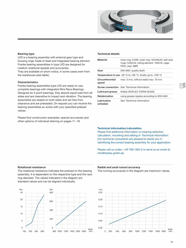
Bearing type LVD is a bearing assembly with external gear type and housing rings made of steel and integrated bearing element. Franke bearing assemblies in type LVD are designed for medium rotational speeds and accuracies. They are available on short notice, in some cases even from the warehouse (see table).
Characteristics Franke bearing assemblies type LVD are ready-to-use, complete bearings with integrated Wire Race Bearings. Designed as 4-point bearings, they absorb equal load from all sides and are insensitive to impact and vibration. The bearing assemblies are sealed on both sides and set free from clearance and are preloaded. On request you can receive the bearing assemblies ex works with your specified preload values.
Please find construction examples, special accuracies and other options of individual tailoring on pages 11 – 19.
Technical details
Material Inner ring: C45N, outer ring: 42CrMo4V, ball race rings: 54SiCr6, rolling element: 100Cr6, cage: PA12, seal: NBR
Gear DIN 3967, quality 8e25
Temperature in use –30 °C to +80 °C, briefly up to +100 °C
Circumferential speed
max. 5 m/s, without seals max. 10 m/s
Screw connection See 'Technical information'.
Lubricant grease Klüber ISOFLEX TOPAS NCA52
Relubrication using grease nipples according to DIN 3405
Lubrication schedule
See 'Technical information'.
Technical information/calculationPlease find additional information on bearing selection, calculation, mounting and setting in 'Technical information'. Our technical consultants are pleased to assist you in identifying the correct bearing assembly for your application.
Please call us under: +49 7361 920-0 or send us an email at: [email protected].
Rotational resistance The rotational resistance indicates the preload on the bearing assembly. It is dependent on the respective type and the race ring diameter. The values indicated in the diagram are standard values and can be aligned individually.
Radial and axial runout accuracy The running accuracies in the diagram are maximum values.
55

T1
HH
1 H2
T
Ø D
M
H1
10
Ø DiØ La
Ø Dah8
Ø LiØ KK
Ø DiH8
Ø dw
Ø D1
A
A
A
AA
Grease nipple DIN 3405D1-M5 up to KKØ 250 mmD1-M8 from KKØ 300 mm
Bearing Assemblies Aluminium design/toothed belt gear type
Type LVE
KKØ Dimensionsmm
D1 D H H1 T M T1 H2100 – 250 11 6.6 34+/-0,4 27 6.8 M 6 10 22300 – 350 15 9.0 38+/-0,4 31 9.0 M 8 15 26400 – 450 18 11.0 44+/-0,5 37 11.0 M 10 15 32500 – 600 20 14.0 49+/-0,5 42 13.0 M 12 20 35
700 – 1000 20 14.0 53+/-0,5 45 13.0 M 12 20 381200 – 1400 26 18.0 60+/-0,5 52 17.5 M 16 20 441600 – 1800 26 18.0 90+/-0,5 82 17.5 M 16 25 69
KKØ Dimensions Fixing/mounting
Load rating Stat. moment Effective range diameter dw
Weight Availability
mm per ring kN kNm mmDah8 DiH8 La Li C0a C0r Ca Cr C0m AT10 z
LVE0100 150 50 135 65 6x 54 25 18 16 1 165,52 52 1,20LVE0150 200 100 185 115 6x 82 39 22 19 3 216,45 68 1,80LVE0200 250 150 235 165 8x 110 52 24 21 5 264,20 83 2,40 from storesLVE0250 300 200 285 215 8x 138 65 26 23 8 324,68 102 3,00LVE0300 360 240 340 260 12x 166 78 28 24 12 378,79 119 5,00 from storesLVE0350 410 290 390 310 14x 196 92 30 26 16 429,72 135 5,80LVE0400 470 330 445 355 14x 424 199 54 47 40 490,20 154 9,50 from storesLVE0450 520 380 495 405 14x 477 224 57 49 57 541,13 170 10,70LVE0500 580 420 550 450 14x 530 249 59 51 62 598,42 188 15,10LVE0600 680 520 650 550 16x 635 299 63 54 63 700,28 220 18,20LVE0700 790 610 750 650 22x 746 351 67 58 123 814,87 256 25,90LVE0800 890 710 850 750 24x 852 401 70 61 160 929,47 292 29,60LVE0900 990 810 950 850 24x 958 451 73 63 203 1028,14 323 33,30LVE1000 1090 910 1050 950 26x 1068 503 76 66 251 1126,82 354 37,00LVE1200 1300 1100 1265 1135 30x 1573 740 98 85 444 1330,54 418 59,90LVE1400 1500 1300 1465 1335 36x 1835 864 104 90 604 1527,89 480 69,90LVE1600 1730 1470 1685 1515 42x 2105 991 109 95 793 1763,44 554 161,00LVE1800 1930 1670 1885 1715 46x 2367 1114 114 99 1003 1967,16 618 181,10
56

100 200 400 600 800 1000 1200 1400 1600 1800
25
20
15
10
5
0
Nm Nm800
600
400
200
0KKØmm
mm0,30
0,20
0,15
0,10
0,05
0,00KKØmm 0 200 400 600 800 1000 1200 1400 1600 1800
Bearing type LVE is a bearing assembly with toothed belt gear type and housing rings made of aluminium and integrated bearing element. Franke bearing assemblies in type LVE are designed for medium rotational speeds and accuracies. They are available on short notice, in some cases even from the warehouse (see table).
Characteristics Franke bearing assemblies type LVE are ready-to-use, complete bearings with integrated Wire Race Bearings. Designed as 4-point bearings, they absorb equal load from all sides and are insensitive to impact and vibration. The bearing assemblies are sealed on both sides and set free from clearance and are preloaded. On request you can receive the bearing assemblies ex works with your specified preload values.
Please find construction examples, special accuracies and other options of individual tailoring on pages 11 – 19.
Technical details
Material Inner/outer ring: AlZnMgCu05, ball race rings: 54SiCr6, rolling element: 100Cr6, cage: PA12, seal: NBR
Gear Profile T10, AT10 or HTD8
Temperature in use –30 °C to +80 °C, briefly up to +100 °C
Circumferential speed
max. 5 m/s, without seals max. 10 m/s
Screw connection See 'Technical information'.
Lubricant grease Klüber ISOFLEX TOPAS NCA52
Relubrication using grease nipples according to DIN 3405
Lubrication schedule
See 'Technical information'.
Technical information/calculationPlease find additional information on bearing selection, calculation, mounting and setting in 'Technical information'. Our technical consultants are pleased to assist you in identifying the correct bearing assembly for your application.
Please call us under: +49 7361 920-0 or send us an email at: [email protected].
Rotational resistance The rotational resistance indicates the preload on the bearing assembly. It is dependent on the respective type and the race ring diameter. The values indicated in the diagram are standard values and can be aligned individually.
Radial and axial runout accuracy The running accuracies in the diagram are maximum values.
57
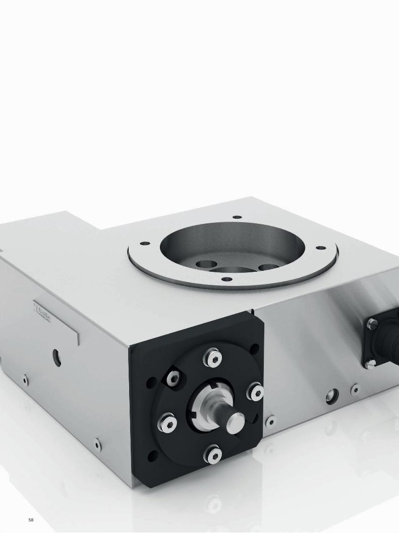
58
Rotary Tables
Type Characteristic KKØ Page
LTA Worm drive/highly dynamic 100, 200 60 – 61LTB Worm drive/highly accurate 125, 175, 265, 400 62 – 63
59

I
66
X/10 deep (LTA100)12 deep (LTA200)
Ø BØ A
Ø EØ FØ G
Ø U
W
RQB
G150
6060
33
32
AM4
TS
K
29
V
2212
P
N
MM
oun
ting
surf
ace
H
884
12
A
B
O
L1
L2L2
Ø 9
-0.0
1Ø
52 -
0.0
3
Grease nipples according to DIN 3405
Rotary Tables Worm drive/highly dynamic
Type LTA
Rated ØA B Ø E
H7/6 deep
Ø F Ø G Ø G1H7/12 deep
H I K L1 L2 M N O P Q R S T U V W X Orderno.
100 85 70 45 30 30 155 125 65 62,5 91,5 70 96,0 65,0 61 99,5 69,5 17 2 4 x Ø 6,6 39 17 4 x M 6 91800A
200 175 160 130 110 110 255 220 70 110,0 139,0 165 145,5 114,5 63 147,0 117,0 22 7 6 x Ø 9,0 39 22 6 x M 8 91801A
60

Characteristics Franke rotary tables of type LTA are lightweight, compact, ready-to-use positioning units. They are highly resilient and deliver outstanding radial and axial run accuracy. Franke rotary tables type LTA are versatile in use and are well-suited to light processing applications and also for dynamic handling and assembly applications.
Material
Baseplate Aluminium
Housing V2A
Ball race rings 54SiCr6
Rolling element 100Cr6
Worm wheel Wear-resistant bronze alloy
Worm shaft CK45N hardened and ground
Technical details
Mounting position
any, preferably horizontal
Lubrication with bearing grease via grease nipples
Optional Inductive proximity switch, flange/coupling to mount the motor, motorization
Performance overview
LTA100 LTA200Radial and axial accuracy µm 30 30Positioning accuracy sec 160 120Repeatability sec 20 14Load rating C0 kN 17,5 43Load rating C kN 9 18Overturning moment C0m Nm 289 433Input speed N1max U/min 1800 2200Reduction ratio i 18 36Output speed N2max U/min 100 61Input torque M1max Nm 5 5Output torque M2max Nm 54 108Operating temperature °C -10 to +80 -10 to +80Weight kg 5,5 10
61

Y1
ZZ
LTB175 LTB400LTB125LTB265
GG G O
U2U1W
S
T
Ø V
4
Y2
X
Ø V
2
Ø V
1
Ø V
3
Ø A
OO
Ø BØ C
Ø DØ E
Ø FØ GØ H
K
Q
N
X3
X2
O
X1
Y
P
R ML
View X (shown rotated by 90°) 135°
90°
View Y
LTB125
LTB175LTB265LTB400
Rotary Tables Worm drive/highly accurate
Type LTB
Rated ØA B Cg6 DH7 E FH7 G H K L M N O P Q R S T U1 U2 V1
g6 V2g6 V3
g6 V4g6 W
125 100 – 70 70 100 150 165 75 – 10 4 x M 5 4 x 7.0 5 34 5 112 60 67.5 67.5 6 22 6 22 135175 126 – 102 70 102 178 – 82 – 12 6 x M 6 3 x 6.6 4 31 4 152 63 98.0 98.0 6 52 6 52 196265 200 150 – 105 150 230 250 90 4 16 6 x M 10 4 x 10.0 – 43 5 171 81 95.0 98.0 8 38 6 38 193400 340 300 200 190 270 380 400 100 4 16 6 x M 10 6 x 11.0 5 43 5 229 139 124.0 127.0 8 38 6 38 251
Rated Ø X1 X2 X3 Y1 Y2 Z Order no.125 21.8 26 2 x M 4 / 16 low + 2 x M 4 / 8 low 8 9 2.8 91042A175 50.0 32 4 x M 4 / 16 low 18 18 4.0 91043A265 45.0 26 4 x M 5 / 24 low 10 7 2.5 91044A400 45.0 26 4 x M 5 / 24 low 9 6 2.5 91045A
Grease nipples according to DIN 3405
62

Characteristics Franke rotary tables of type LTB are open-center, ready-to-use positioning units. They are highly resilient, lightweight (aluminium housing) and deliver outstanding ATR accuracy and discrimination. Franke rotary tables of type LTB are versatile in use and are primarily suited to movement and positioning tasks in the fields of measurement, testing and orientation.
Material
Housing Aluminium corrugated
Ball race rings 54SiCr6
Rolling element 100Cr6
Worm wheel Wear-resistant bronze alloy
Worm shaft CK45N hardened and ground
Technical details
Mounting position
any, preferably horizontal
Lubrication with bearing grease via grease nipples
Optional Inductive proximity switch, flange/coupling to mount the motor, motorization
Performance overview
LTB125 LTB175 LTB265 LTB400Radial and axial accuracy µm 20 20 20 30Positioning accuracy sec 80 80 70 50Repeatability sec 16 14 10 8Load rating C0 kN 2 2,6 4,2 14,1Overturning moment C0m Nm 110 140 310 1780Input speed N1max U/min 2500 2500 2500 2500Reduction ratio i 360 360 360 360Output speed N2max U/min 7 7 7 7Input torque M1max Nm 0,7 0,9 1,5 2Output torque M2max Nm 70 75 160 290Operating temperature °C -10 to +80 -10 to +80 -10 to +80 -10 to +80Weight kg 3 6 10 27
63

64

Accessories Wire Race Bearings
Product Type/Characteristic Page
Standard cages LBK, plastic band cage, incl. balls 66Special cages Made of hard fabric, non-corrosive, brass 66Washers For Screw sizes M 6 to M 16 67Seals Standard sleeve seal 67
Acc
esso
ries
65

Accessories Wire Race Bearings
Cage size dw Dimensions Order no.mm inches mm (by the meter)
h g d fLBK5 5.0 3/16 7.6 1.5 7.5 0.4 78916ALBK6 6.0 8.6 1.6 9.2 0.4 78917ALBK8 8.0 5/16 10.6 2.0 12.0 0.6 78918ALBK9.5 9.5 3/8 12.6 2.5 14.0 0.7 78920ALBK10 10.0 13.2 2.5 14.0 0.7 78921ALBK11 11.0 13.2 2.5 14.0 0.7 78922ALBK12V 12.0 17.0 3.5 14.0 0.7 600997LBK15 15.0 18.6 3.0 18.6 0.7 78924ALBK16 16.0 19.6 3.0 20.0 0.7 78925ALBK20 20.0 25/32 24.2 3.5 26.0 0.7 78926A
dw h x g h1 x g1 Order no.mm mm mm
5.0 2 x 10 2.7 x 13 on request6.0 2 x 12 2.7 x 15 8.0 3 x 15 4.0 x 18 9.0 3 x 16 4.0 x 18
9.525 3 x 18 4.0 x 2012.0 4 x 20 5.5 x 23 16.0 5 x 26 6.5 x 30 20.0 6 x 31 7.5 x 35 25.0 8 x 38 10.0 x 43 30.0 8 x 45 10.0 x 50 40.0 12 x 56 14.0 x 61 50.0 15 x 80 17.5 x 88
Material: PA12 or TPU
The band cage is segmented in the length required respec-tively and delivered fitted with balls and ready-to-use. The number of balls req uired is based on:
Z = number of bearings KKØ = raceway diameter t = bearing separation
(tolerance ±0.2)
The number of segments is dependent on the bearing diameter and the ball size. Indicative values:
The band cage can also be created in one part for special applications.
Special cagesFlat cages made of hard fabric, non-corrosive, brass
Material: Hard fabric, brass, non-corrosive
It is mandatory to use a flat cage for temperatures exceeding 100 °C and with bearing diameters larger than 20 mm. Special solutions, including complete non-corrosive properties or radiation resistance, are also possible.Special cages in the form of band or prong-type cages are available for special requirements in terms of ambient conditions or mounting space.
Franke also delivers materials such as plastic, non-corrosive, brass and Teflon.
Band cages made of hard fabric, non-corrosive, brass
Prong-type cages
KKØ mm < 200 200 – 399 400 – 799 800 – 1500
Number of segments 3 – 4 4 – 6 6 – 8 8 – 12
Standard cagesBand cages for the LBK series
Z = KKØ · π = 1d[ ]
66

Size Dimensions Order no.mm Thickness mm
a b d f h 0.025 0.1 0.15 0.2 0.25 0.3 0.5 1.0 M 6 11.0 24.4 7 5 11.0 79015A 79034A 79035A 79036A 79037A 79038A 79039A 79040A M 8 14.7 34.2 9 6 13.5 79041A 79023A 79042A 79000A 79026A 79043A 79044A 79045A M 10 16.4 42.3 11 7 16.0 79046A 79012A 79010A 79011A 79047A 79048A 79049A 79050A M 12 20.3 46.0 13 8 18.0 79118A 79051A 79052A 79053A 79054A 79055A 79056A 79065A M 16 25.4 54.0 17 11 24.0 79119A 79024A 79066A 79057A 79058A 79059A 79060A 79061A
WashersLarger bearings and bearing elements use washers to simplify adjustment between the separate inner and outer rings. The washers are made of non-corrosive sheet steel. It is sensible to include in the design specifications a theoretical initial gap of 0.5 mm for the adjustment.
Please find additional data in 'Technical information' on page 76.
SealsBy standard, the bearing assemblies are fitted with sleeve seals S120. Temperature: –30 °C to +80 °C (NBR). Max. circumferential speed: 5 m/s.
The seals can be ordered by the meter in order to seal the construction (e.g. when using a bearing element). The joint is then bonded using adhesive agent Loctite 401®.
Mounting dimensions
Profile Dimensions Material Preload. Weight Order no.mm mm kg/m
S H B±0.3 B1±0.2 D VL1
09 3.5 4.8 2.5 0.8 Perbunan 70NBR/221 0.5…1.5 0.016 0092810 4.2 5.3 3.0 0.8 Perbunan 70NBR/221 0.5…1.5 0.026 0908010 4.2 5.3 3.0 0.8 Viton 0.5…1.5 0.026 4606215 5.5 8.5 4.3 1.0 Perbunan 70NBR/221 0.5…2.0 0.051 09190
1 Depending on bearing assembly (approx. 1 Nm/m seal).
Special seals are available on request. Franke offers Viton seals for high temperatures or aggressive media.
Pro-file
Mounting dimensions Groove dimension
mm mmS c c2 a1 a2 t+0.2 s+0.1
09 4.5 + 1 5.2 + 1 3.1…4.1 4.0…5.0 3.5 2.35+/– 0.05
10 5 + 1 5.5 + 1 3.6...4.6 4.3...5.3 4.2 2.9+/– 0.05
15 8 + 1.5 9.0 + 1.5 6.3...7.7 7.5...9.0 5.5 3.9Important notice: First measure the seal, then cut the groove.
Acc
esso
ries
67

68

Technical InformationWire Race Bearings
Table of contents Page
1 Wire Race Bearing selection 701.1 Parameters to select bearings 1.2 Static and dynamic load-bearing capacity, calculation
2 Calculation 70 – 712.1 Terms, dimensions2.2 Static calculation 2.2.1 Axial and radial factors 2.2.2 Recommended Static safety Sst
2.3 Dynamic calculatio 2.3.1 Nominal service life 2.3.2 Axial and radial loads 2.3.3 Axial and moment stress and axial stress with Fr = 0, Mk = 0 2.3.4 Radial and moment stress and radial stress with Fr = 0, Mk = 0
3 Calculation example of bearing elements 71 – 72
4 Design and production of the bearing bed 72 – 744.1 Wire bed design for bearing elements type LEL4.2 Wire bed design for bearing elements type LER4.3 Wire bed design for slim bearings type LSA/LSB
5 Assembly 74 – 775.1 Installation and adjustment of bearing elements 5.1.1 Setting using washers 5.1.2 Setting using solid adjustment5.2 Installation and adjustment of slim bearings 5.2.1 Setting using washers 5.2.2 Setting using solid adjustment
6 Installation and setting of bearing assemblies 77 – 796.1 Lubrication and maintenance6.2 Initial lubrication resp. re-newed lubrication6.3 Relubrication and lubrication schedule6.4 Lubrication and lubrication schedule for the gear6.5 Screw connections6.6 Gear6.7 Tolerances and accuracy
7 Rotary tables 797.1 Load-bearing capacity7.2 Temperature range7.3 Lubrication7.4 Options
Tech
nica
l in
form
atio
n
69

Mk
Fr
Fa
Technical Information Wire Race Bearings
1 Wire Race Bearing selection
The ideal selection, i.e. selection of bearings should take place before the start of design. The underlying question is which bearing series will delver the greatest benefits in the respective application:
• Bearing elements (type LEL, LER): - Maximum possible integration capacity - Series application to meet cost constraints - Greatest possible flexibility based on preload, runnability
and diameter ranges• Slim bearings (type LSA, LSB, LSC):
- Simple, compact integration within your designs - Cost-effective alternative to standard slim bearings - Not preloaded bearings
• Bearing assemblies (type LVA, LVB, LVD, LVE): - Ready-to-use standard bearings with a large
selection range - Preloaded free from clearance
(optimized for rigidity, speed and service life) - Available on short notice
• Bearing assemblies (type LVC): - Ready-to-use standard bearings for high
rotational speeds• Rotary systems (type LTA):
- Robust, standard rotary table with worm drive for handling and standard positioning tasks at high speed
• Rotary systems (type LTB): - Rotary table with worm gear for highly accurate
measurement and positioning tasks
1.1 Parameters to select bearings• Proper dimensions and material information of bearings• Loads with load collectives and corresponding time
quotients in %• Rotational speed, i.e. number of swinging movements and
swing angles per time unit• Circumferential forces that the gear transfers• Other operating conditions such as temperature, vacuum,
clean room, moisture, etc.
An approximate bearing selection is possible based on our calculation formulae. The relevant data on this are found on the individual type pages.
1.2 Static and dynamic load-bearing capacity – calculation
The details listed in the catalogue concerning static and dynamic load rating are sufficient for initial design, but not for scaling. The load ratings mentioned are the radial load ratings. The static axial radial moment load ratings, i.e. the dynamic axial and radial load ratings are required to deliver ideal design. The axial values are higher by approx. facto 2.
2 Calculation
All forces and moments acting on the bearing must be summarised in centrally prevalent forces Fa and Fr, also the consequent moments Ma, by vector addition. We would be pleased to make the calculation on your behalf for complex load incidences and load collectives with changing load and speed.
2.1 Terms, dimensionsC dynamic rated load (N)C0 static rated load (N)Fa centrally-acting axial force (N)Fr centrally-acting radial force (N)KKØ ball pitch diameter = (D + d)/2 (M)Ln nominal service life (h)Mk tilting moment (Nm)n Number of revolutions (min – 1)P dynamic equivalent load (N)P0 static equivalent load (N)Sst static safetyX radial factorY axial factorZ moment factor
70

Ball pitch diameter KKØ = 400 mm
Fa
Fr1
Fr2
2.2 Static calculationA static calculation is sufficient if the bearing is at rest or is subject to load at low rotational and swinging movement with a circumferential speed in the ball pitch of V ≤ 0.1 m/s. A bearing with sufficient load-bearing capacity would be chosen once the recommended static safety is reached.
Sst =1
(–)Fa Fr M
Coa Cor Com
2.2.1 Axial and radial factors
2.2.2 Recommended Static safety Sst
2.3 Dynamic calculationA circumferential speed of v > 0.1 m/s will require a static and dynamic calculation, in which the static safety Sst must at least reach the recommended value for each load.
2.3.1 Nominal service life
Lh =C · 106
(h)P 60 · n
2.3.2 Axial and radial loads
P = X · FR + Y · Fa (N)
X0 Y0
All bearing types 1.0 0.47
Ball diameter > 6 Sst
During smooth operation without vibration > 1.8During normal operation > 2.5During pronounced impact loads and high requirements concerning run accuracy
> 8
Fa ≥ 1Fr
Fa < 1Fr
X Y X YAll bearing types 1.26 0.45 0.86 0.86
2.3.3 Axial and moment load and axial load with Fr = 0, Mk = 0
P = Y · Fa + Z · Mk
(N)KKØ
2.3.4 Radial and moment load and radial load with Fr = 0, Mk = 0
P = X · Fr + Z · Mk
(N)KKØ
We are pleased to conduct the calculation on your behalf for the load case radial, axial and moment load.
3 Calculation example of bearing elements
Load data:Load case A (static load)
Central axial force consisting of net weight + load Fa = 22 kN
Radial force from working pressure Fr1 = 4.2 kN
0 <Mk ≤ 0.5
Fa · KKØ
Mk ≤ 0.5Fa · KKØ
Y Z X ZAll bearing types 0.86 1.72 0.45 2.54
0 ≥Mk ≤ 0.5
Fr · KKØ
Mk ≥ 0.5Fr · KKØ
X Z X ZAll bearing types 1.0 1.68 0.86 1.96
( )3
Tech
nica
l in
form
atio
n
71

Ove
rsiz
e f.
So
lid a
dju
stm
ent
0.1
M KKØ-M 0+T
NH
7
~ KKØ+(M+10)
KKØ+M 0+T
KKØ
R 0-0.1
R 0-0.1 R 0-0.1
R 0-0.1
Centering band
Load case B (dynamic load)
Central axial force consisting of net weight + load Fa = 22 kN
Radial force from drive Fr2 = 1.5 kN
Average operating speed n = 9.5 1/min
Calculation for bearing element LEL 4 with KKØ 400 mm.
Data: C0a = 240 kN C0r = 113 kN
Calculation:
Load case A (static load)
Sst =1
=1
Fa + Fr + M 22 + 4,2 + –Coa Cor Com 240 113 –
Safety Sst = 7.8 ( sufficient for bearing in normal operation)
Load case B (dynamic load)
Sst =1
=1
Fa + Fr + M 22 + 1,5 + –Coa Cor Com 240 113 –
Safety Sst = 9.5 ( hence greater than the required minimum safety under 2.2.2)
Service life Lh =29 · 106
= 5200 h20.2 60 · 9.5
(P = 0.86 · 1.5 kN + 0.86 · 22 kN = 20.2 kN)
4 Design and production of the bearing bed
Bearing elements consist of two bearing elements and a multi-part, segmented cage with balls. The race rings are open; their diameter can therefore be altered elastically for mounting.
The balls satisfy quality class 3 (DIN 5401). Only use the balls contained in the delivery. If balls are lost, please replace all other balls also to avoid impeding the runnability of the bearing.
Design and ideal technical production, also the correct setting of preload, are important conditions in ensuring long service life. This guarantees that all raceways are involved in accom-modating the load and that the balls run ideally on their predefined positions.
The design and production of the wire bed differs for the individual bearing elements and slim bearings; the following contains corresponding descriptions.
4.1 Wire bed design for bearing elements type LELThe bearing elements LEL offer the best runnability and running accuracy, but also place the highest demands in design of the wire bed. Here are two scaled diagrams for the most important parameters:
1. Adjustment through grinding (sold adjustment)It is important to take care in the design of the mating components that the housing parts to be joined together are manufactured with oversize to achieve the desired preload in the bearing by grinding the lid.
( )3
Technical Information Wire Race Bearings
72

Und
ersi
ze
M
NH
7
R 0-0.1
R 0-0.1 R 0-0.1
R 0-0.1
KKØ-M 0+T
~ KKØ+(M+10)
KKØ+M 0+T
KKØCentering band
M
NH
7
N-0
.1 0 -0
.05
KKØ-M 0+T
KKØ+M 0+T
KKØ
2. Adjustment using washersIt is important to take care in the design of the mating components that the housing parts to be joined together are manufactured with undersize to achieve the desired preload in the bearing by adding washers.
The dimensions and tolerances are calculated as follows:R = λ – 0.1T = KKØ / 10,000 (dimensions in mm)Oversize for grinding, i.e. undersize for additional washers: 0.1 mmFit tolerance for central fitBore: lower tolerance: +0.01;
upper tolerance: +0.01 +IT6Shaft: upper tolerance: –0.01;
lower tolerance: –0.01 –IT6
In a design sense it is worthwhile to create a separated bearing stator, but the rotor should generally comprise one part only. The individual accuracies influence the required accuracy; accordingly, separated rings should be apportioned 2⁄3 of the radial/axial tolerances, while singe-part rings are apportioned half of the radial/axial tolerances.
Half of the diameter tolerance principally applies to the roundness of the wire bed; the screw-on surface of the connecting construction applies to the axial runout. The center of the wire bed is always the basis for the radial runout.Evenness and parallel quality of the individual components are designed with one half of the overall tolerance.
Take care when designing the mating components that the parallel surfaces that are not joined (e.g. surface above the centering band) is designed with a sufficient interval to ensure they have sufficient space once the bearings have been adjusted. Design the chamfers and radii on the fit in such a
way that the joint surfaces can be screwed together without collisions occurring in the area of the cylinder edges.
In general it is true that the accuracy of the bearing assembly is improved if the wire bed of the separated ring is manufac-tured once the two rings have been screwed together and dowelled using pins. Further, the mounting fit of the bearing must be processed together with the wire bed in one setting. It is sufficient to manufacture the wire bed by means of machining or milling; the recommended surface qualities are < Ra 3.2, as high surface quality has a positive influence on the settling behavior of the bearings.
The wire bed should always be processed in one setting with contours correlated with the centering or runnability; this helps achieve ideal accuracy and service life of the bearing.We recommend protecting the wire bed against wear if soft materials are used (e.g. by anodizing or chemical nickel- plating, etc.).
4.2 Wire bed design for bearing elements type LERThe bearing elements LER offer significantly greater simplicity compared with the LEL series in terms of the mating rotary components. Here it is possible to adjust the bearing using a simple lid plate and washers. Like with the LEL, the wire bed must be separated, and centering of the separated ring is not necessary.
It is important to take care in the design of the mating components for systems with lid that the wire bed fitted with lid is manufactured undersized; this ensures that through addition of washers, the desired preload in the bearing can be reached.
Tech
nica
l in
form
atio
n
73

KKØ-0.01-M 0-T
NH
7
NM
9
KKØ+0.01+M 0+T
KKØ
The information provided in the LEL section applies to the constructive design. The wire bed does not possess any radii that accommodate the race ring, but the tool radii must not be greater than 0.2 mm.
T = KKØ/10.000 (dimensions in mm)Undersize for washers: 0.1 mm
In a design sense it is worthwhile to create a separated bearing stator, but the rotor should generally comprise one part only. The individual accuracies influence the required accuracy; but seeing as the wire bed of the separated ring is also not offset radially, the radial and axial tolerances are divided evenly between the two rings.
Half of the diameter tolerance principally applies to the roundness of the wire bed; the screw-on surface of the connecting construction applies to the axial runout. The center of the wire bed is always the basis for the radial runout.
Evenness and parallel quality of the individual components are designed with one half of the overall tolerance.The mounting fit of the bearing must be processed together with the wire bed in one setting. It is sufficient to manufacture the wire bed by means of machining or milling; the recom-mended surface qualities are < Ra 3.2, as high surface quality has a positive influence on the settling behavior of the bearings.
4.3 Wire bed design for slim bearings type LSAUnlike the bearing elements LEL and LER described above, the LSA bearing elements cannot be adjusted and always come with clearance. According to the specifications listed below, the bearings have a clearance of between 0.02 and 0.08 mm. The wire bed is separated like with the LER; it is not possible to set the clearance.
It is sensible in the constructive design to integrate the outer ring in the separated element of the mating structure, given that assembly, and specifically insertion of the ring in the mating structure, is easier to manage in this way.
The wire bed does not possess any radii that accommodate the race ring, but the tool radii must not be greater than 0.2 mm.T = IT7 for KKØ up to 250 / IT6 for KKØ larger than 250 (dimensions in mm)
Half of the diameter tolerance principally applies to the roundness of the wire bed; the screw-on surface of the connecting construction applies to the axial runout. The center of the wire bed is always the basis for the radial runout.
The mounting fit of the bearing must be processed together with the wire bed in one setting. It is sufficient to manufacture the wire bed by means of machining or milling; the recom-mended surface qualities are < Ra 3.2, as high surface quality has a positive influence on the settling behavior of the bearings.
5 Assembly
5.1 Installation and adjustment of bearing elements
5.1.1 Setting using washersSetting the washers is the most economical and flexible procedure, as it also permits downstream alteration of the rotational resistance. Washers in a variety of thickness can be ordered, dependent on the diameter of the screws (see Accessories p. 67).
Technical Information Wire Race Bearings
74

Requirements:• Separation of the inner or the outer ring construction.• The height of the race ring bed is smaller on one side of the
separated connecting construction: 0.3 to 0.5 mm. This gap is needed to accommodate the washers.
• The separated side of the connecting construction should be fixed in place using a centering band. This is the only means of ensuring that the raceways run parallel.
Installation and setting:The race rings are inserted in the mating structure. Coat the race ring beds with grease to keep the race rings in position during installation. The joints on the opposing race rings in the same component are installed, each offset by approx. 180°. The separated part of the connecting construction is then installed in its intended position.*
The cage elements with the balls are then inserted, and the bearing element is greased (see 6.1 Lubrication and mainte-nance). Before closing the mating structure in the separated side it is important to place the washers on the drill holes of the retaining screws. The thickness is dependent on the constructed gap (see above).
Check the rotational resistance once the screws have been tightened (see 6.5 Screw connections) and the bearing assembly has been rotated approx. 2 to 3 times by 360°. Change the thickness of all washers and repeat the process if the measurement value deviates by more than 5 to 10 %.
*Applies to both setting methods: 2.1 and 2.2.
5.1.2 Setting using solid adjustmentWhen making the setting by means of solid adjustment, the correct dimensions of the adjustment surface are produced by grinding. This method delivers the best accuracies as the separating surface between the separated side of the connecting construction is flush and stress transmission cannot emerge.
Prerequisite:• Separation of the inner or the outer ring construction.• Flange grinding machine in a suitable size.• The height of the race ring bed on the side of the separated
connecting construction is 0.1 mm larger. This oversize is needed for adjustment.
• The separated side of the connecting construction should be fixed in place using a centering band. This determines the parallel nature of the two raceways
Installation and setting:Then the cage segments with the balls are inserted and the bearing assembly is closed with the second separated part of the mating structure (adjustment ring). Use a dial gage to measure the clearance between the inner and outer ring once the screws have been tightened as specified (see 6.5 Screw connections) and the bearing assembly has been rotated approx. 2 to 3 times by 360°. The adjustment ring is then dismantled again and the measurement value registered plus 0.02 to 0.03 mm is ground down using the flat grinder.
A suitable support surface should be selected as early as the design phase to ensure parallel adjustment between this surface and the raceway support. The ring is fitted and the bearing moved as described above once the grinding dust has been thoroughly removed. Then check the rotational resistance. The process must be repeated if this measure-ment value deviates by more than 5 to 10 %. Finally the bearing assembly is lubricated using the fitted lubricant bores (see 6.1 Lubrication and maintenance).
The bearings are designed for continuous operation at temperatures between –10 °C and +70 °C – briefly also for use at up to +120 °C. Circumferential speeds of 10 m/s with grease lubrication and 12 m/s with oil lubrication can be achieved. Setting the preload is an important condition for a long service life of the bearing element. The preload guaran-tees that all raceways are involved in accommodating the load and that the balls run ideally on their predefined positions. Preload is set correctly if the rotational resistance without seals matches the values in the diagram under item 6.
Note: Setting the preload is advisable as tolerances will exist and require compensation even in the event of ideal produc-tion.
Tech
nica
l in
form
atio
n
75

5.2 Installation and adjustment of slim bearings Slim bearings type LSA
The LSA is a consistent redevelopment of the Wire Race Bear-ing technology. In LSA two race wires are combined into one. Instead of the four race rings you find in conventional Wire Race Bearings, the LSA has just two. The 4-point principle is maintained by the special profile of the raceways. This makes mounting and adjustment just as simple as for conventional slim bearings with gains in load bearing capacity and rating.Assembly takes place according to the following stages:1. Clean the components with a clean cloth that does not lint.2. Grease the race rings (rear side).3. Insert the inner ring of the LSA into the inner ring of the
mating structure. Take care that a gap separates the ends of the race ring ends.
4. Place the cage and the outer race ring on the inner race ring. Hold together the ends of the outer race ring in such away that the ball cage cannot slip out.
5. Position and axially insert the outer ring.6. Position and screw on the lid.
Installation proposal:
Slim bearings type LSBSlim bearings of the type LSB are highly resilient, ready-to-use Wire Race Bearings that can be fitted very easily and in a compact mounting space. In slim bearings LSB the bearing element (four ball race rings with ground raceway and with retained balls) is embedded in an inner and outer sleeve made of steel. The sleeves are separated circumferentially and form a ready-to-fit bearing that is directly integrated in the respec-tive design. Unlike standard closed and ground slim bearings, the clearance in Franke slim bearings is not dependent on adjusting the seat of the outer and inner ring. Therefore the installation and dismantling are easier and do not require special tools or thermal treatment.
The bearings are designed for continuous operation at temperatures between –10 °C and +70 °C – briefly also for use at up to +100 °C. Circumferential speeds of 10 m/s with grease lubrication and 12 m/s with oil lubrication can be achieved. Setting the preload is an important condition for a long service life of the slim bearing. The preload guarantees that all raceways are involved in accommodating the load and that the balls run ideally on their predefined positions.
Preload is set correctly if the rotational resistance without seals matches the values in the diagram under item 6.
Note: Setting the preload is advisable as tolerances will exist and require compensation even in the event of ideal produc-tion.
Slim bearings type LSCSlim bearings type LSC consist of a slim bearing type LSA (techn. Info see above), which is embedded in elastomer sleeves. These sleeves ensure the sealing of the bearing and simultaneously take over adjustment and tolerance compen-sation. Slim bearings type LSC therefore must not be adjusted after mounting.
The installation involves the following steps:1. Clean components with a clean, lint-free cloth.2. Grease either elastomer sleeves or cylindrical surface of the mating structure.3. Carefully insert the bearing without twisting the elastomer.4. Put on the cover and screw it.
5.2.1 Setting using washersSetting the washers is the most economical and flexible procedure, as it also permits downstream alteration of the rotational resistance. Washers in a variety of thickness can be ordered, dependent on the diameter of the screws (see Accessories p. 67).
Requirements:• Separation of the inner or the outer ring construction.• The height of the race ring bed is smaller on one side of the
separated connecting construction: 0.3 to 0.5 mm. This gap is needed to accommodate the washers.
• The separated side of the connecting construction can be fixed in place using a centering band to improve parallel adjustment of the raceways.
Installation proposal A:The slim bearing is inserted in the connecting construction. Before closing the connecting construction in the separated side, the washers are fitted on the drill holes of the retaining
Technical Information Wire Race Bearings
76

screws. The thickness is dependent on the constructed gap (see above). Check the rotational resistance once the screws have been tightened (see 6.5 Screw connections) and the bearing assembly has been rotated approx. 2 to 3 times by 360°. Change the thickness of all washers and repeat the process if the measurement value deviates by more than 5 to 10 %.
5.2.2 Setting using solid adjustmentWhen making the setting by solid adjustment, the correct dimensions of the adjustment surface are produced by grinding. This method delivers the best accuracies as the separating surface between the separated side of the connecting construction is flush and stress transmission cannot emerge.
Prerequisite:• Separation of the inner or the outer ring construction.• Flange grinding machine in a suitable size.• The height of the wire bed on the side of the separated
connecting construction is 0.1 mm larger. This oversize is needed for adjustment.
• The separated side of the connecting construction can be fixed in place using a centering band. This improves the parallel adjustment between the two raceways.
Installation and setting:The slim bearing is inserted in the connecting construction and the bearing is closed with the second separated part of the mating structure (adjustment ring). Use a dial gage to measure the clearance between the inner and outer ring once the screws have been tightened as specified (see 6.5 Screw connections) and the bearing has been rotated approx. 2 to 3 times by 360°. The adjustment ring is then dismantled again and the measurement value registered plus 0.02 to 0.03 mm is ground down using the flat grinder. A suitable support surface should be selected as early as the design phase to ensure parallel adjustment between this surface and the raceway support. The ring is fitted and the bearing moved as de-scribed above once the grinding dust has been thoroughly
removed. Then check the rotational resistance. The process must be repeated if this measurement value deviates by more than 5 to 10 %.
6 Installation and setting of bearing assemblies
Franke bearing assemblies are ready-to-use complete bearings – no matter whether they are standard bearings from the catalogue or customer-specific versions. The specified or defined run accuracy, rotational resistance, rigidity and general properties are dependent on both the connecting construction and on the accuracy and completeness of the data provided. For this reason these are particularly important factors.
6.1 Lubrication and maintenanceSufficient lubrication is necessary in order to keep friction low and to permanently protect the bearing against corrosion. All lubricants age in a manner that limits their suitability for use. Fully synthetic lubricants deliver the best age-resilience. Use ISOFLEX TOPAS NCA52 (special grease by the firm Klüber, designation according to DIN 51502 is: KHC2 N-50) to lubricate Franke bearings for the first time. The age-resilience of this lubricant is approximately three years. This lubricant is also recommended for use in the bearing elements.
High-quality lithium soap greases on a polyalphaolefine basis or mineral oil basis, i.e. according to DIN 51825-K2 K-40, are suitable as alternatives. Please clarify any questions concern-ing lubricants, e.g. mixability, aggressiveness, extreme temperatures, disposal, areas of use and such like, with the respective manufacturer.
6.2 Initial lubrication resp. re-newed lubrication The lubricant quantity that a Wire Race Bearing requires for lubrication is relatively low and adjusts automatically depen-ding on the speed. If the lubricant quantity is too high, the creep may produce elevated temperatures that restrict or eliminate the lubricating properties. The service life of the
Tech
nica
l in
form
atio
n
77

bearing is reduced substantially by greater wear. The lubricant quantity is dependent on the calculated empty space inside the bearing assembly. The calculated volume must be filled with lubricant to 20 to 30 %. 30 to 40 % is recommended for swivel bearings.Franke bearing assemblies are factory lubricated. Bearing elements and slim bearings are treated with anti-corrosive oil for transport and must be lubricated during assembly.
6.3 Relubrication and lubrication scheduleThe lubricating capacity drops due to mechanical load and ageing. It is therefore necessary to replenish or entirely replace the existing lubricant volume (e.g. when severely contaminated). Turn the bearing during relubrication. When possible relubricate at operating temperature.
The relubrication volume is calculated as follows:m = KKØ x H1 / 3 x XH1 = bearing ring height in mmKKØ = ball pitch diameter in mmm = relubricant volume in gX = factor according to Table 1 in mm–1
Relubrication schedule: A precise definition of the schedule is dependent on the specific use and can therefore only be determined accurately by experiment (for approximate values see Table 1). Correlate the metered time with the activated application time to determine factor X (Table 2).
Note: Standard bearings only need one fitted relubrication facility, as the bearing movement itself evenly distributes the lubricant. At least three relubrication facilities are needed for swivel bearings (3 x 120°).
Vu Intervalm/s h
0 bis < 3 5000 3 bis < 5 1000 5 bis < 8 600
3 bis < 10 200
Table 1: Relubrication schedule
Table 2: Relubrication intervals
Circulation lubrication with oil is essentially possible and should be coordinated with the respective lubricant manufac-turer. Lubricant-free bearings are available for special applications (e.g. clean room or ultra-high vacuum).
Interval Weekly Monthly Yearly 2–3 yearsX 0.002 0.003 0.004 0.005
Calculation example: Bearing assembly type LVA, KKØ 500 mm, Circumferential speed 3 m/s Activation time approx. 16 h/day The relubrication schedule for 3 m/s is 1000 h (see Table 1) = 1000 (h)/16 (h/day) = 63 days ~ 3 months for 16 h/day activation time
Relubrication should take place quarterly. Consequently, factor X (Table 2) is rounded off and amounts to 0.003. The dimensions H1 is 42 mm (see catalogue page 48).
m = 500 mm x 42 / 3 mm–1 x 0.003 g = 21 g The relubrication quantity is therefore 21 g ISOFLEX TOPAS NCA52 after every three months. The lubricant has a service life of three years.
6.4 Lubrication and lubrication schedule for the gear Automatic gear lubrication is recommended. Sufficiently lubricate the gear and sprocket by hand before commission-ing. The lubrication schedule is dependent on the design and the circumferential speed and must therefore be considered individually.
6.5 Screw connections Always check the number of screws and their diameter for attachment to the connecting construction. Interval X from retaining screw to retaining screw should not exceed 125 mm to prevent bridges developing. Tighten the fixing screws crosswise in relation to the screw quality using a torque spanner – as defined in the data contained in Table 3.
Table 3: Tightening torque
Apply the specified tightening torque to tighten the screws in order to prevent any subsidence. When possible complete this when the screws are not exposed to any tensile forces. Inspect the screws after approximately 100 operating hours and then every 1000 operating hours thereafter. This period may also be substantially shorter for special operating conditions (e.g. exposed to severe vibration).
QualityNm
8.8 12.9 M 6 10 17 M 8 25 41 M 10 49 83 M 12 86 145 M 16 210 355
Technical Information Wire Race Bearings
78

6.6 GearBy standard Franke provides a straight gear without hardening (material 42CrMo4V); special gears on request. The material, design and quality can be modified at any time to suit individual wishes.
The catalogue data concerning permissible circumferential forces were determined using the permissible bending force in the tooth root. The maximum forces refer to extreme load, e.g. caused by short-term impact due to start-up or braking. These values are approximate values and can only be determined precisely by means of gear calculations account-ing for both components (sprocket and bearing assembly).
6.7 Tolerances and accuracyAll tolerances and accuracies are listed on the respective catalogue pages. The greatest levels of accuracy are achieved if the constructive design of the mating parts takes place in such a way that the handling of all diameters and surfaces relating to each other can take place in one setting. The running accuracies indicated in the catalogue are average values and may be improved by restricting the tolerances. The tolerance data T = IT6 or T = IT7 refer to the diameter-depend-ent basic tolerances according to DIN ISO 286 (see Table 4).
Table 4: Tolerance data DIN ISO 286 T1 (11.90)
Rated dimension range Basic tolerancesmm µm
above ... to IT6 IT7 80... 120 22 35
120... 180 25 40 180... 250 29 46 250... 315 32 52 315... 400 36 57 400... 500 40 63 500... 630 44 70 630... 800 50 80 800... 1000 56 90
1000... 1250 66 105 1250... 1600 78 125
7 Rotary tables
Franke rotary tables are highly resilient and particularly suited to assembly, measurement and testing tasks. All rotary tables have a compactly structured aluminium housing with integrat-ed Franke components. A worm gear guarantees high accuracy, even under continuous load. The rotary tables have low net weight, yet remain extremely rigid to tilting. Please find precise technical data on this in the catalogue pages.
7.1 Load-bearing capacityThe recommended safety for Franke rotary tables is Sst ≥ 3 for simple load conditions and Sst ≥ 6 for dynamic, alternating load and lifting conditions. Franke is pleased to calculate load and service life as required.
7.2 Temperature rangeThe rotary tables can be used in operating temperatures from –10 °C to +80 °C. Extended temperature ranges are available on request.
7.3 LubricationIn general, all standard rotary tables are factory fitted with long-term lubrication using the Wire Race Bearing grease ISOFLEX TOPAS NCA52. Depending on their use, it is recommended to relubricate Franke rotary tables half yearly or yearly.
7.4 Options• One or two integrated inductive proximity switch(es).• Free selection of trip cam position• Fixtures for motors as required by customer• Motorization with stepper or servo motor, depending
on the application• Rotary encoder fitted at the second shaft end of the
worm shaft• Complete automation solution
Please observe our assembly and maintenance instruc-tions for each item.
Relubrication quantity per lubrication point g
Lubrication point left front rightLTA100 1 1LTA200 1 1LTB125 2LTB175 3LTB265 3LTB400 4
Tech
nica
l in
form
atio
n
79

Guided RollerRollers with groove in an O-arrangement
Profiled raceways
Aluminium bodyfor cassettes and guide rails
The video Function principle of Linear Systems at YouTube Search term "Franke Linear Systems"
Linear guideFranke Dynamic
80

Linear Systems
Aluminium Linear Systems by Franke are the best solution when it comes to speed and lightweight construction. They are highly dynamic, fast, quiet and mainte-nance-free. Franke offers individual profiles and cassettes, motorized units with measurement systems and controls, also linear modules with direct drive, custom-ized to your requirements. The patented system of Guided Rollers® moves the rollers and raceways ideally.The modular structure of our Linear Systems allows us to satisfy individual customer wishes. Different rail profiles and roller shoes, special cassettes and variable track widths are among the examples.
Linear module
Linear motor drive
Line
ar S
yste
ms
81

82

Why Franke Linear Systems?
Convincing features of Franke aluminium Linear Systems include their lightweight structure and quiet and easy run. They can be customized to your application in a variety of different ways.
Aluminium – lightweightThe guide rails and cassette bodies are made of aluminium. As a user, this will provide you with several advantages:
• Lightweight designs • Homogeneous material properties in
assemblies with aluminium profiles • Low moved masses• Low drive energy required• High dynamism and speed
The Franke principle – inserted steel wires as racewaysWire raceways made of steel or non-corrosive inserted in the aluminium body ensure high resilience and load capacity. The wire raceway is aligned with the width of the rollers and keeps them precisely on track.
4-point system to accommodate forces from all directionsThe large-scale rollers rotate in needle or ball bearings and are arranged crosswise. They accommodate load from all directions and are convincing in their rapid response behavior.
Line
ar S
yste
ms
83
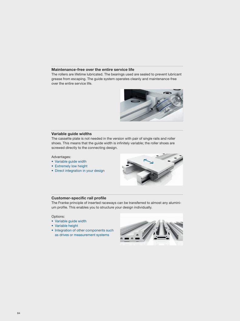
Maintenance-free over the entire service lifeThe rollers are lifetime lubricated. The bearings used are sealed to prevent lubricant grease from escaping. The guide system operates cleanly and maintenance-free over the entire service life.
Variable guide widthsThe cassette plate is not needed in the version with pair of single rails and roller shoes. This means that the guide width is infinitely variable; the roller shoes are screwed directly to the connecting design.
Advantages:• Variable guide width • Extremely low height • Direct integration in your design
Customer-specific rail profileThe Franke principle of inserted raceways can be transferred to almost any alumini-um profile. This enables you to structure your design individually.
Options:• Variable guide width • Variable height • Integration of other components such
as drives or measurement systems
84

Customer-specific materials and surfacesWe offer linear guides with non-corrosive or non-magnetic race rods and individually refined surfaces for special requirements.
Examples:• Non-corrosive raceways
(corrosion protection) • Non-magnetic raceways • Clean room-compatible guides • Anodized in different colors
Customer-specific cassettes and roller shoesThe form of cassettes and roller shoes can be integrated in your application. For instance, mounts for drive spindles can be integrated.
Customer specifications:• Special dimensions • Variable number of rollers • Variable adjustment of the rollers
Motorized modules: Type FTI with toothed belt driveModules in type FTI have raceways and toothed belt drive protection through integration on the inside of the aluminium profile.
Characteristics:• Protected raceways • Lightweight construction
(aluminium body) • Attractive price
Please find additional information on the linear module type FTI on pages 112 – 113.
Motorized modules: Type FTH with integrated linear motorFranke Linear Systems are available fitted with drive and control. Modules in type FTH have an integrated linear motor and are convincing in their:
• High dynamism • High travel speed • Low height • Lightweight construction
(aluminium body)
Please find additional information on the linear module type FTH on pages 114 – 117.
New
Line
ar S
yste
ms
85

86

Accuracy along the entire lineFranke Linear Systems. For individual customer requirements. Highly dynamic. Maintenance-free. Ideal movement. Quiet. Aluminium for lightness. For speed and lightweight design.
Line
ar S
yste
ms
87

88

Linear guides
Type Characteristic Page
FDA Aluminium roller guide/Standard 90 – 91FDB Aluminium roller guide/LowCost 92 – 93FDC Aluminium roller guide/Non-Corrosive 94 – 95FDD Aluminium roller guide/Non-Magnetic 96 – 97FDE Aluminium roller guide/Lubricant-Free 98 – 99FDG Aluminium roller guide/Non-Corrosive LowCost 100 – 101FDH Aluminium roller guide/Highly Dynamic 102 – 103
89

Order no. Order code
Cassette Double rail84494A84396A84441A84363A84364A84365A
e.g. FDA 25 D 1500
Type
Size
Length in mm**
Double rail
Linear guidesAluminium roller guide Franke Dynamic
Type FDA/Standard
Size Dimensionsmm
A L H B1 B2 D D1 D2 E1 E2 H1 H2 H3 H4 L2 L3 T T112 37 64 19 12.0 12.50 3.4 6 M 4 25 30 14.7 4.0 1.4 5.5 10 40 5.5 815 47 78 24 15.5 15.75 4.5 8 M 5 30 38 18.7 5.0 2.0 8.0 10 60 6.0 1020 63 92 30 21.0 21.00 5.5 10 M 6 40 53 22.6 7.0 2.0 11.0 10 60 8.0 1225 70 98 36 23.0 23.50 6.6 11 M 8 45 57 27.0 8.5 2.5 13.0 10 60 10.0 1635 100 135 48 32.0 34.00 9.0 15 M 10 62 82 37.0 10.5 3.5 20.0 12 80 11.5 2045 120 165 60 45.0 37.50 11.0 18 M 12 80 100 46.0 13.5 4.0 22.0 16 105 14.5 24
Size Load rating Moment load ratings*, cassette WeightN Nm kg
C C0 M0cx Mcx M0cy/M0cz Mcy/Mcz Cassette Rail/m
12 2800 3000 27 25 43 40 0.1 0.415 4200 3400 37 45 58 72 0.2 0.820 5400 5400 76 76 111 111 0.4 0.925 9000 10100 158 142 222 198 0.5 1.835 12500 18000 423 294 559 388 1.4 3.245 21200 25900 827 678 983 806 2.5 5.5
Order numbersLoad ratings, weight
Dimensions
**Guide rails in one piece up to 4000 mm. Longer stroke lengths are coupled.
Cassette + double rail
*See technical information for more information on moment load ratings
90

Order no. Order code
RSP Pair of single rails84495A84395A84442A84367A84368A84369A
e.g. FDA 25 E 1500
Type
Size
Length in mm**
Single rail
Order numbersLoad ratings, weight
Dimensions
**Guide rails in one piece up to 4000 mm. Longer stroke lengths are coupled.
Pair of roller shoes + pair of single rails
Size Dimensionsmm
B5 H5 B3 B4 D3 D4 D5 E3 E4 E5 E6 E7 E8 E9 H6 T3 a b12 24.4 15.0 12.00 11.9 M 3 8 3 3.4 29 57 9.7 3.4 5.5 4.9 4 6.0 4.5 9.515 30.9 19.0 15.25 15.2 M 4 10 4 4.4 34 68 12.4 4.9 7.0 5.9 5 7.5 5.0 12.520 40.9 23.0 20.00 20.4 M 5 10 4 4.9 42 80 16.9 5.9 9.5 5.9 5 8.0 7.5 16.025 48.4 27.5 25.00 22.9 M 5 14 6 6.4 48 84 19.4 7.4 12.0 8.9 7 5.0 10.5 17.535 68.9 37.5 35.00 32.9 M 6 14 6 8.9 67 117 28.4 8.9 17.0 8.9 7 7.5 12.5 26.045 82.4 46.5 45.00 36.4 M 8 14 6 9.9 83 146 30.9 9.9 22.0 8.9 7 9.5 15.5 31.0
Size Load rating Moment load rating* RSP WeightN Nm kg
C C0 M0cx Mcx M0cy/M0cz Mcy/Mcz RSP Rail/m
12 2800 3000 1.5 (B+30.3) 1.4 (B+30.3) 43 40 0.07 0.415 4200 3400 1.7 (B+36.5) 2.1 (B+36.5) 58 72 0.12 0.820 5400 5400 2.7 (B+47.0) 2.7 (B+47.0) 111 111 0.23 1.025 9000 10100 5.0 (B+58.4) 4.5 (B+58.4) 222 198 0.34 1.935 12500 18000 9.0 (B+85.0) 6.3 (B+85.0) 559 388 0.99 3.545 21200 25900 12.9 (B+109.0) 10.6 (B+109.0) 983 806 1.79 5.6
*See technical information for more information on moment load ratings
91

Order no. Order code
Cassette Double rail84494L84396L84441L84363L84364L84365L
e.g. FDB 25 D 1500
Type
Size
Length in mm**
Double rail
Type FDB/LowCost
Size Dimensionsmm
A L H B1 B2 D D1 D2 E1 E2 H1 H2 H3 H4 L2 L3 T T112 37 64 19 12.0 12.50 3.4 6 M 4 25 30 14.7 4.0 1.4 5.5 10 40 5.5 815 47 78 24 15.5 15.75 4.5 8 M 5 30 38 18.7 5.0 2.0 8.0 10 60 6.0 1020 63 92 30 21.0 21.00 5.5 10 M 6 40 53 22.6 7.0 2.0 11.0 10 60 8.0 1225 70 98 36 23.0 23.50 6.6 11 M 8 45 57 27.0 8.5 2.5 13.0 10 60 10.0 1635 100 135 48 32.0 34.00 9.0 15 M 10 62 82 37.0 10.5 3.5 20.0 12 80 11.5 2045 120 165 60 45.0 37.50 11.0 18 M 12 80 100 46.0 13.5 4.0 22.0 16 105 14.5 24
Size Load rating Moment load ratings*, cassette WeightN Nm kg
C C0 M0cx Mcx M0cy/M0cz Mcy/Mcz Cassette Rail/m
12 620 170 1.6 5.7 2.4 8.9 0.1 0.415 700 230 2.5 7.5 4.0 12.0 0.2 0.820 940 300 4.0 13.0 6.0 19.0 0.4 0.925 1500 700 11.0 23.0 15.0 32.0 0.5 1.835 3100 1400 32.0 72.0 42.0 95.0 1.4 3.245 6300 2700 86.0 200.0 103.0 238.0 2.5 5.5
Order numbersLoad ratings, weight
Dimensions
**Guide rails in one piece up to 4000 mm. Longer stroke lengths are coupled.
Cassette + double rail
*See technical information for more information on moment load ratings
Linear guidesAluminium roller guide Franke Dynamic
92

Order no. Order code
RSP Pair of single rails84495L84395L84442L84367L84368L84369L
e.g. FDB 25 E 1500
Type
Size
Length in mm**
Single rail
Order numbersLoad ratings, weight
Dimensions
**Guide rails in one piece up to 4000 mm. Longer stroke lengths are coupled.
Pair of roller shoes + pair of single rails
Size Dimensionsmm
B5 H5 B3 B4 D3 D4 D5 E3 E4 E5 E6 E7 E8 E9 H6 T3 a b12 24.4 15.0 12.00 11.9 M 3 8 3 3.4 29 57 9.7 3.4 5.5 4.9 4 6.0 4.5 9.515 30.9 19.0 15.25 15.2 M 4 10 4 4.4 34 68 12.4 4.9 7.0 5.9 5 7.5 5.0 12.520 40.9 23.0 20.00 20.4 M 5 10 4 4.9 42 80 16.9 5.9 9.5 5.9 5 8.0 7.5 16.025 48.4 27.5 25.00 22.9 M 5 14 6 6.4 48 84 19.4 7.4 12.0 8.9 7 5.0 10.5 17.535 68.9 37.5 35.00 32.9 M 6 14 6 8.9 67 117 28.4 8.9 17.0 8.9 7 7.5 12.5 26.045 82.4 46.5 45.00 36.4 M 8 14 6 9.9 83 146 30.9 9.9 22.0 8.9 7 9.5 15.5 31.0
Size Load rating Moment load rating* RSP WeightN Nm kg
C C0 M0cx Mcx M0cy/M0cz Mcy/Mcz RSP Rail/m
12 620 170 0.08 (B+30.3) 0.30 (B+30.3) 2.4 8.9 0.07 0.415 700 230 0.10 (B+36.5) 0.35 (B+36.5) 4.0 12.0 0.12 0.820 940 300 0.15 (B+47.0) 0.50 (B+47.0) 6.0 19.0 0.23 1.025 1500 700 0.35 (B+58.4) 0.70 (B+58.4) 15.0 32.0 0.34 1.935 3100 1400 0.70 (B+85.0) 1.50 (B+85.0) 42.0 95.0 0.99 3.545 6300 2700 1.40 (B+109.0) 3.10 (B+109.0) 103.0 238.0 1.79 5.6
*See technical information for more information on moment load ratings
93

Order no. Order code
Cassette Double rail84494AN84396AN84441AN84363AN84364AN84365AN
e.g. FDC 25 D 1500
Type
Size
Length in mm**
Double rail
Type FDC/Non-Corrosive
Size Dimensionsmm
A L H B1 B2 D D1 D2 E1 E2 H1 H2 H3 H4 L2 L3 T T112 37 64 19 12.0 12.50 3.4 6 M 4 25 30 14.7 4.0 1.4 5.5 10 40 5.5 815 47 78 24 15.5 15.75 4.5 8 M 5 30 38 18.7 5.0 2.0 8.0 10 60 6.0 1020 63 92 30 21.0 21.00 5.5 10 M 6 40 53 22.6 7.0 2.0 11.0 10 60 8.0 1225 70 98 36 23.0 23.50 6.6 11 M 8 45 57 27.0 8.5 2.5 13.0 10 60 10.0 1635 100 135 48 32.0 34.00 9.0 15 M 10 62 82 37.0 10.5 3.5 20.0 12 80 11.5 2045 120 165 60 45.0 37.50 11.0 18 M 12 80 100 46.0 13.5 4.0 22.0 16 105 14.5 24
Size Load rating Moment load ratings*, cassette WeightN Nm kg
C C0 M0cx Mcx M0cy/M0cz Mcy/Mcz Cassette Rail/m
12 1100 1200 11 10 17 16 0.1 0.415 2700 3000 33 29 52 46 0.2 0.820 4300 5000 71 61 103 89 0.4 0.925 5800 8300 132 92 184 128 0.5 1.835 10000 14500 343 237 452 312 1.4 3.245 17000 20400 651 542 774 645 2.5 5.5
*See technical information for more information on moment load ratings
Order numbersLoad ratings, weight
Dimensions
**Guide rails in one piece up to 4000 mm. Longer stroke lengths are coupled.
Cassette + double rail
Linear guidesAluminium roller guide Franke Dynamic
94

Order no. Order code
RSP Pair of single rails84495AN84395AN84442AN84367AN84368AN84369AN
e.g. FDC 25 E 1500
Type
Size
Length in mm**
Single rail
*See technical information for more information on moment load ratings
Order numbersLoad ratings, weight
Dimensions
**Guide rails in one piece up to 4000 mm. Longer stroke lengths are coupled.
Size Dimensionsmm
B5 H5 B3 B4 D3 D4 D5 E3 E4 E5 E6 E7 E8 E9 H6 T3 a b12 24.4 15.0 12.00 11.9 M 3 8 3 3.4 29 57 9.7 3.4 5.5 4.9 4 6.0 4.5 9.515 30.9 19.0 15.25 15.2 M 4 10 4 4.4 34 68 12.4 4.9 7.0 5.9 5 7.5 5.0 12.520 40.9 23.0 20.00 20.4 M 5 10 4 4.9 42 80 16.9 5.9 9.5 5.9 5 8.0 7.5 16.025 48.4 27.5 25.00 22.9 M 5 14 6 6.4 48 84 19.4 7.4 12.0 8.9 7 5.0 10.5 17.535 68.9 37.5 35.00 32.9 M 6 14 6 8.9 67 117 28.4 8.9 17.0 8.9 7 7.5 12.5 26.045 82.4 46.5 45.00 36.4 M 8 14 6 9.9 83 146 30.9 9.9 22.0 8.9 7 9.5 15.5 31.0
Size Load rating Moment load rating* RSP WeightN Nm kg
C C0 M0cx Mcx M0cy/M0cz Mcy/Mcz RSP Rail/m
12 1100 1200 0.6 (B+30.3) 0.6 (B+30.3) 17 16 0.07 0.415 2700 3000 1.5 (B+36.5) 1.4 (B+36.5) 52 46 0.12 0.820 4300 5000 2.5 (B+47.0) 2.2 (B+47.0) 103 89 0.23 1.025 5800 8300 4.2 (B+58.4) 2.9 (B+58.4) 184 128 0.34 1.935 10000 14500 7.3 (B+85.0) 5.0 (B+85.0) 452 312 0.99 3.545 17000 20400 10.2 (B+109.0) 8.5 (B+109.0) 774 645 1.79 5.6
Pair of roller shoes + pair of single rails
95

Order no. Order code
Cassette Double rail84363P e.g. FDD 25 D 1500
Type
Size
Length in mm**
Double rail
Type FDD/Non-Magnetic
Size Dimensionsmm
A L H B1 B2 D D1 D2 E1 E2 H1 H2 H3 H4 L2 L3 T T125 70 98 36 23.0 23.50 6.6 11 M 8 45 57 27.0 8.5 2.5 13.0 10 60 10.0 16
Size Load rating Moment load ratings*, cassette WeightN Nm kg
C C0 M0cx Mcx M0cy/M0cz Mcy/Mcz Cassette Rail/m
25 1200 1600 25 18 35 25 0.5 1.8
Order numbersLoad ratings, weight
Dimensions
**Guide rails in one piece up to 4000 mm. Longer stroke lengths are coupled.
Cassette + double rail
*See technical information for more information on moment load ratings
Linear guidesAluminium roller guide Franke Dynamic
96

Order no. Order code
RSP Pair of single rails84367P e.g. FDD 25 E 1500
Type
Size
Length in mm**
Single rail
Order numbersLoad ratings, weight
Dimensions
**Guide rails in one piece up to 4000 mm. Longer stroke lengths are coupled.
Size Dimensionsmm
B5 H5 B3 B4 D3 D4 D5 E3 E4 E5 E6 E7 E8 E9 H6 T3 a b25 48.4 27.5 25.00 22.9 M 5 14 6 6.4 48 84 19.4 7.4 12.0 8.9 7 5.0 10.5 17.5
Size Load rating Moment load rating* RSP WeightN Nm kg
C C0 M0cx Mcx M0cy/M0cz Mcy/Mcz RSP Rail/m
25 1200 1600 0.8 (B+58.4) 0.6 (B+58.4) 35 25 0.34 1.9
Pair of roller shoes + pair of single rails
*See technical information for more information on moment load ratings
97
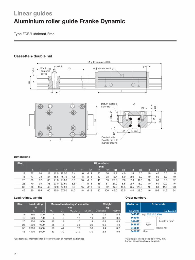
Order no. Order code
Cassette Double rail84494T84396T84441T84363T84364T84365T
e.g. FDE 25 D 1500
Type
Size
Length in mm**
Double rail
Type FDE/Lubricant-Free
Order numbersLoad ratings, weight
**Guide rails in one piece up to 4000 mm. Longer stroke lengths are coupled.
Size Dimensionsmm
A L H B1 B2 D D1 D2 E1 E2 H1 H2 H3 H4 L2 L3 T T112 37 64 19 12.0 12.50 3.4 6 M 4 25 30 14.7 4.0 1.4 5.5 10 40 5.5 815 47 78 24 15.5 15.75 4.5 8 M 5 30 38 18.7 5.0 2.0 8.0 10 60 6.0 1020 63 92 30 21.0 21.00 5.5 10 M 6 40 53 22.6 7.0 2.0 11.0 10 60 8.0 1225 70 98 36 23.0 23.50 6.6 11 M 8 45 57 27.0 8.5 2.5 13.0 10 60 10.0 1635 100 135 48 32.0 34.00 9.0 15 M 10 62 82 37.0 10.5 3.5 20.0 12 80 11.5 2045 120 165 60 45.0 37.50 11.0 18 M 12 80 100 46.0 13.5 4.0 22.0 16 105 14.5 24
Size Load rating Moment load ratings*, cassette WeightN Nm kg
C C0 M0cx Mcx M0cy/M0cz Mcy/Mcz Cassette Rail/m
12 350 400 4 3 6 5 0.1 0.415 600 700 8 6 12 10 0.2 0.820 700 900 12 9 17 14 0.4 0.925 1200 1600 25 18 35 25 0.5 1.835 2000 2500 58 44 76 58 1.4 3.245 4400 5500 180 140 210 170 2.5 5.5
Dimensions
Cassette + double rail
*See technical information for more information on moment load ratings
Linear guidesAluminium roller guide Franke Dynamic
98

Order no. Order code
RSP Pair of single rails84495T84395T84442T84367T84368T84369T
e.g. FDE 25 E 1500
Type
Size
Length in mm**
Single rail
Order numbersLoad ratings, weight
**Guide rails in one piece up to 4000 mm. Longer stroke lengths are coupled.
Dimensions
Size Dimensionsmm
B5 H5 B3 B4 D3 D4 D5 E3 E4 E5 E6 E7 E8 E9 H6 T3 a b12 24.4 15.0 12.00 11.9 M 3 8 3 3.4 29 57 9.7 3.4 5.5 4.9 4 6.0 4.5 9.515 30.9 19.0 15.25 15.2 M 4 10 4 4.4 34 68 12.4 4.9 7.0 5.9 5 7.5 5.0 12.520 40.9 23.0 20.00 20.4 M 5 10 4 4.9 42 80 16.9 5.9 9.5 5.9 5 8.0 7.5 16.025 48.4 27.5 25.00 22.9 M 5 14 6 6.4 48 84 19.4 7.4 12.0 8.9 7 5.0 10.5 17.535 68.9 37.5 35.00 32.9 M 6 14 6 8.9 67 117 28.4 8.9 17.0 8.9 7 7.5 12.5 26.045 82.4 46.5 45.00 36.4 M 8 14 6 9.9 83 146 30.9 9.9 22.0 8.9 7 9.5 15.5 31.0
Size Load rating Moment load rating* RSP WeightN Nm kg
C C0 M0cx Mcx M0cy/M0cz Mcy/Mcz RSP Rail/m
12 350 400 0.20 (B+30.3) 0.20 (B+30.3) 6 5 0.07 0.415 600 700 0.35 (B+36.5) 0.30 (B+36.5) 12 10 0.12 0.820 700 900 0.40 (B+47.0) 0.33 (B+47.0) 17 14 0.23 1.025 1200 1600 0.80 (B+58.4) 0.60 (B+58.4) 35 25 0.34 1.935 2000 2500 1.20 (B+85.0) 0.90 (B+85.0) 76 58 0.99 3.545 4400 5500 2.70 (B+109.0) 2.20 (B+109.0) 210 170 1.79 5.6
Pair of roller shoes + pair of single rails
*See technical information for more information on moment load ratings
99

Order no. Order code
Cassette Double rail84494LN84396LN84441LN84363LN84364LN84365LN
e.g. FDG 25 D 1500
Type
Size
Length in mm**
Double rail
Type FDG/Non-Corrosive LowCost
Order numbersLoad ratings, weight
**Guide rails in one piece up to 4000 mm. Longer stroke lengths are coupled.
Size Dimensionsmm
A L H B1 B2 D D1 D2 E1 E2 H1 H2 H3 H4 L2 L3 T T112 37 64 19 12.0 12.50 3.4 6 M 4 25 30 14.7 4.0 1.4 5.5 10 40 5.5 815 47 78 24 15.5 15.75 4.5 8 M 5 30 38 18.7 5.0 2.0 8.0 10 60 6.0 1020 63 92 30 21.0 21.00 5.5 10 M 6 40 53 22.6 7.0 2.0 11.0 10 60 8.0 1225 70 98 36 23.0 23.50 6.6 11 M 8 45 57 27.0 8.5 2.5 13.0 10 60 10.0 1635 100 135 48 32.0 34.00 9.0 15 M 10 62 82 37.0 10.5 3.5 20.0 12 80 11.5 2045 120 165 60 45.0 37.50 11.0 18 M 12 80 100 46.0 13.5 4.0 22.0 16 105 14.5 24
Size Load rating Moment load ratings*, cassette WeightN Nm kg
C C0 M0cx Mcx M0cy/M0cz Mcy/Mcz Cassette Rail/m
12 620 170 1.6 5.7 2.4 8.9 0.1 0.415 700 230 2.5 7.5 4.0 12.0 0.2 0.820 940 300 4.0 13.0 6.0 19.0 0.4 0.925 1500 700 11.0 23.0 15.0 32.0 0.5 1.835 3100 1400 32.0 72.0 42.0 95.0 1.4 3.245 6300 2700 86.0 200.0 103.0 238.0 2.5 5.5
Dimensions
Cassette + double rail
*See technical information for more information on moment load ratings
Linear guidesAluminium roller guide Franke Dynamic
100

Order no. Order code
RSP Pair of single rails84495LN84395LN84442LN84367LN84368LN84369LN
e.g. FDG 25 E 1500
Type
Size
Length in mm**
Single rail
Order numbersLoad ratings, weight
**Guide rails in one piece up to 4000 mm. Longer stroke lengths are coupled.
Dimensions
Size Dimensionsmm
B5 H5 B3 B4 D3 D4 D5 E3 E4 E5 E6 E7 E8 E9 H6 T3 a b12 24.4 15.0 12.00 11.9 M 3 8 3 3.4 29 57 9.7 3.4 5.5 4.9 4 6.0 4.5 9.515 30.9 19.0 15.25 15.2 M 4 10 4 4.4 34 68 12.4 4.9 7.0 5.9 5 7.5 5.0 12.520 40.9 23.0 20.00 20.4 M 5 10 4 4.9 42 80 16.9 5.9 9.5 5.9 5 8.0 7.5 16.025 48.4 27.5 25.00 22.9 M 5 14 6 6.4 48 84 19.4 7.4 12.0 8.9 7 5.0 10.5 17.535 68.9 37.5 35.00 32.9 M 6 14 6 8.9 67 117 28.4 8.9 17.0 8.9 7 7.5 12.5 26.045 82.4 46.5 45.00 36.4 M 8 14 6 9.9 83 146 30.9 9.9 22.0 8.9 7 9.5 15.5 31.0
Size Load rating Moment load rating* RSP WeightN Nm kg
C C0 M0cx Mcx M0cy/M0cz Mcy/Mcz RSP Rail/m
12 620 170 0.08 (B+30.3) 0.30 (B+30.3) 2.4 8.9 0.07 0.415 700 230 0.10 (B+36.5) 0.35 (B+36.5) 4.0 12.0 0.12 0.820 940 300 0.15 (B+47.0) 0.50 (B+47.0) 6.0 19.0 0.23 1.025 1500 700 0.35 (B+58.4) 0.70 (B+58.4) 15.0 32.0 0.34 1.935 3100 1400 0.70 (B+85.0) 1.50 (B+85.0) 42.0 95.0 0.99 3.545 6300 2700 1.40 (B+109.0) 3.10 (B+109.0) 103.0 238.0 1.79 5.6
Pair of roller shoes + pair of single rails
*See technical information for more information on moment load ratings
101

Order no. Order code
Cassette Double rail84363S84364S84365S
e.g. FDH 25 D 1500
Type
Size
Length in mm**
Double rail
Type FDH/Highly Dynamic
Order numbersLoad ratings, weight
**Guide rails in one piece up to 4000 mm. Longer stroke lengths are coupled.
Size Dimensionsmm
A L H B1 B2 D D1 D2 E1 E2 H1 H2 H3 H4 L2 L3 T T125 70 98 36 23.0 23.50 6.6 11 M 8 45 57 27.0 8.5 2.5 13.0 10 60 10.0 1635 100 135 48 32.0 34.00 9.0 15 M10 62 82 37.0 10.5 3.5 20.0 12 80 11.5 2045 120 165 60 45.0 37.50 11.0 18 M12 80 100 46.0 13.5 4.0 22.0 16 105 14.5 24
Size Load rating Moment load ratings*, cassette WeightN Nm kg
C C0 M0cx Mcx M0cy/M0cz Mcy/Mcz Cassette Rail/m
25 7500 3700 58 118 81 165 0.5 1.835 13400 8100 189 315 250 416 1.4 3.245 24300 14400 461 777 548 924 2.5 5.5
Dimensions
Cassette + double rail
*See technical information for more information on moment load ratings
Linear guidesAluminium roller guide Franke Dynamic
102

Order no. Order code
RSP Pair of single rails84367S84368S84369S
e.g. FDH 25 E 1500
Type
Size
Length in mm**
Single rail
Order numbersLoad ratings, weight
**Guide rails in one piece up to 4000 mm. Longer stroke lengths are coupled.
Dimensions
Size Dimensionsmm
B5 H5 B3 B4 D3 D4 D5 E3 E4 E5 E6 E7 E8 E9 H6 T3 a b25 48.4 27.5 25.00 22.9 M 5 14 6 6.4 48 84 19.4 7.4 12.0 8.9 7 5.0 10.5 17.535 68.9 37.5 35.00 32.9 M 6 14 6 8.9 67 117 28.4 8.9 17.0 8.9 7 7.5 12.5 26.045 82.4 46.5 45.00 36.4 M 8 14 6 9.9 83 146 30.9 9.9 22.0 8.9 7 9.5 15.5 31.0
Size Load rating Moment load rating* RSP WeightN Nm kg
C C0 M0cx Mcx M0cy/M0cz Mcy/Mcz RSP Rail/m
25 7500 3700 1.8 (B+58.4) 3.7 (B+58.4) 81 165 0.34 1.935 13400 8100 4.0 (B+85.0) 6.7 (B+85.0) 250 416 0.99 3.545 24300 14400 7.2 (B+109.0) 12.2 (B+109.0) 548 924 1.79 5.6
Pair of roller shoes + pair of single rails
*See technical information for more information on moment load ratings
103

104

Linear tables/linear modules
Type Characteristic Page
FTB Spindle drive 106 – 107FTC Outer guide/spindle/toothed belt drive 108 – 109FTD Inner guide/toothed belt drive 110 – 111FTI Inner guide/toothed belt drive 112 – 113FTH Outer guide/spindle/linear motor drive 114 – 117
105

Linear tablesSpindle drive
Type FTB
FTB06A/FTB06B
106
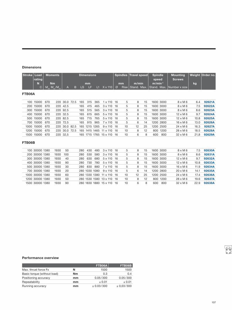
Dimensions
Stroke Load rating
Moments Dimensions Spindles Travel speed Spindle speed
Mounting Screws
Weight Order no.
N Nm mm mm m/min m/min-1 kgC Mcx Mcy/Mcz A B LS LF L1 X x 110 Ø Rise Stand. Max. Stand. Max. Number x size
FTB06A
100 15000 670 220 30.0 72.5 165 315 365 1 x 110 16 5 8 15 1600 3000 8 x M 6 6.4 92621A200 15000 670 220 42.5 165 415 465 3 x 110 16 5 8 15 1600 3000 8 x M 6 7.5 92622A300 15000 670 220 92.5 165 515 565 3 x 110 16 5 8 15 1600 3000 8 x M 6 8.6 92623A400 15000 670 220 32.5 165 615 665 5 x 110 16 5 8 15 1600 3000 12 x M 6 9.7 92624A500 15000 670 220 82.5 165 715 765 5 x 110 16 5 8 15 1600 3000 12 x M 6 10.8 92625A700 15000 670 220 72.5 165 915 965 7 x 110 16 5 6 14 1200 2800 16 x M 6 13.0 92626A
1000 15000 670 220 30.0 82.5 165 1215 1265 9 x 110 16 10 12 25 1200 2500 24 x M 6 16.3 92627A1200 15000 670 220 30.0 72.5 165 1415 1465 11 x 110 16 10 8 12 800 1200 28 x M 6 18.5 92628A1500 15000 670 220 32,5 165 1715 1765 15 x 110 16 10 6 8 600 800 32 x M 6 21,8 92629A
FTB06B
100 30000 1380 1930 50 280 430 480 3 x 110 16 5 8 15 1600 3000 8 x M 6 7.5 92630A200 30000 1380 1930 100 280 530 580 3 x 110 16 5 8 15 1600 3000 8 x M 6 8.6 92631A300 30000 1380 1930 40 280 630 680 5 x 110 16 5 8 15 1600 3000 12 x M 6 9.7 92632A400 30000 1380 1930 90 280 730 780 5 x 110 16 5 8 15 1600 3000 12 x M 6 10.8 92633A500 30000 1380 1930 30 280 830 880 7 x 110 16 5 8 15 1600 3000 16 x M 6 11.9 92634A700 30000 1380 1930 20 280 1030 1080 9 x 110 16 5 6 14 1200 2800 20 x M 6 14.1 92635A
1000 30000 1380 1930 60 280 1330 1380 11 x 110 16 10 12 25 1200 2500 24 x M 6 17.4 92636A1200 30000 1380 1930 50 280 1530 1580 13 x 110 16 10 8 12 800 1200 28 x M 6 19.6 92637A1500 30000 1380 1930 90 280 1830 1880 15 x 110 16 10 6 8 600 800 32 x M 6 22.9 92638A
Performance overview
FTB06A FTB06BMax. thrust force Fx N 1500 1500Basic torque (without load) Nm 0.3 0.4Positioning accuracy mm 0.05 / 300 0.05 / 300Repeatability mm ≤ 0.01 ≤ 0.01Running accuracy mm ± 0.03 / 300 ± 0,03 / 300
107

Stroke
Stroke
Linear modulesOuter guide/spindle/toothed belt drive
Type FTC
FTC 15-25
Size Dimensionsmm
AA AZ BB DD CF EC EE EG FB FF FH FT GG JJ KB KB1 KC KE KF KG KH KL KL1 KM KN KP ZZ15 154 10 144 60 72.5 32.5 53 39 40 64 39.5 73.5 50 120 10j6 6 15 22.0 37.0 57 30 24 17 2 13 M 5 1220 197 11 187 80 91.0 42.0 62 48 52 84 51.7 88.0 64 160 10j6 10 18 17.5 36.5 61 38 26 31 2 20 M 6 1225 276 24 266 120 117.0 63.0 75 57 76 110 77.0 118.5 90 240 16j6 15 32 23.5 48.5 85 50 34 43 3 28 M 8 16
Size Dimensionsmm
A A1 B B1 C E G H J K M Z15 125 100 22 22.0 41 27 M 5 10 117 21.5 40.5 M 620 150 125 25 25.5 52 36 M 6 12 152 28.5 49.0 M 625 200 175 25 33.0 87 70 M 6 12 200 43.0 62.0 M 6
108

Order numbers
Performance overview
Stroke Order no.
mm FTC 15 FTC 20 FTC 25Toothed belt Spindles Toothed belt Spindles Toothed belt Spindles
100 92700A 92700S 92734A 92734S 92768A 92768S200 92701A 92701S 92735A 92735S 92769A 92769S300 92702A 92702S 92736A 92736S 92770A 92770S400 92703A 92703S 92737A 92737S 92771A 92771S500 92704A 92704S 92738A 92738S 92772A 92772S600 92705A 92705S 92739A 92739S 92773A 92773S700 92706A 92706S 92740A 92740S 92774A 92774S800 92707A 92707S 92741A 92741S 92775A 92775S900 92708A 92708S 92742A 92742S 92776A 92776S
1000 92709A 92709S 92743A 92743S 92777A 92777S1100 92710A 92710S 92744A 92744S 92778A 92778S1200 92711A 92745A 92745S 92779A 92779S1300 92712A 92746A 92746S 92780A 92780S1400 92713A 92747A 92747S 92781A 92781S1500 92714A 92748A 92748S 92782A 92782S1600 92715A 92749A 92749S 92783A 92783S1700 92716A 92750A 92750S 92784A 92784S1800 92717A 92751A 92751S 92785A 92785S1900 92718A 92752A 92752S 92786A 92786S2000 92719A 92753A 92753S 92787A 92787S2200 92721A 92755A 92789A 92789S2400 92723A 92757A 92791A 92791S2600 92725A 92759A 92793A 92793S2800 92727A 92761A 92795A 92795S3000 92729A 92763A 92797A 92797S3200 92731A 92765A 92799A 92799S3400 92733A 92767A
Rated load: stat./dyn. Co/C N 3400 / 4200 5400 / 5400 15100 / 13500Max. moment (MCX/MCY, MCZ) Nm 81 / 190 133 / 338 483 / 922Max. speed m/s 2 0.25 3 0.25 / 0.5 5 0.25 / 0.5 / 1.25 / 2.5Linear travel per motor revolution mm 60 5 60 5 / 10 100 5 / 10 / 25Mass: Basic weight/per m stroke/moved
kg 1.9 / 3.3 / 0.75 1.8 / 4 / 0.75 3.6 / 7 / 1.18 3.7 / 7 / 1.18 8.9 / 10 / 2.5 8.8 / 13.2 / 2.5
Max. speed per drive module min –1 2000 3000 3000Max. effective thrust force FX < 1 m/s N 55 250 150 600 425 1500at speed 1 – 2 m/s N 50 250 120 600 375 1500at speed > 2 m/s N 100 300Basic torque (without load) Nm 0.4 0.2 0.2 0.2 / 0.3 0.6 0.3 / 0.4 / 0.5Max. permissible drive torque < 1 m/s Nm 0.9 2.3 1.5 / 2.8 10 4.2 / 7.5 / 20at speed 1 – 2 m/s Nm 0.9 0.6 2 9.5at speed > 2 m/s Nm 1.8 7.5Max. acceleration/delay m/s² 10 10 10 10 10 10Repeatability mm/m ±0.05 ±0.05 ±0.05Positioning accuracy* mm/m ±0.15 ±0.15 ±0.15Running accuracy mm ±0.03 / 300 ±0.03 / 300 ±0.03 / 300
*Depending on a variety of factors. 109

StrokeStroke
Linear modulesInner guide/toothed belt drive
Type FTD
FTD 15-35
Size Dimensionsmm
A B C E G H J K M S V X Y15 218 88 93 25 M 5 10 178 21.5 31 85 64 40 M 620 262 112 116 28 M 6 12 218 28.5 38 100 64 40 M 635 347 147 175 18 M 6 12 263 43.0 49 124 90 60 M 6
Size Dimensionsmm
CE CF EC EF FB FH KF KB* KC KL KJ KN KO KP KR KS* KT KU ZZ15 42 52.5 79 27 92 39.5 49.0 16H7 18.3 5 8 34 21.7 30 16h7 16H7 82 M 8 820 56 66.5 100 36 116 51.7 62.0 22H7 24.8 6 12 53 30.0 30 22h7 22H7 106 M 10 1035 87 92.5 158 70 164 77.0 79.5 32H7 35.3 10 19 75 41.0 35 32h7 32H7 144 M 12 10
*Other dimensions for KS and KB on request.110

Performance overview
Rated load: stat./dyn. Co/C N 3400/4200 5400/5400 18000/12500Max. moment (MCX/MCY, MCZ) Nm 45/274 76/460 294/1233Max. speed m/s 10 10 10Max. acceleration/delay m/s² 40 40 40Max. effective thrust force FX < 1 m/s N 1070 1870 3120at speed 1 – 3 m/s N 890 1560 2660at speed > 3 m/s N 550 1030 1940Basic torque (without load) Nm 1.2 2.2 3.2Mass: Basic weight/per m stroke/moved kg 3.8 / 4.3 / 1.0 7.7 / 6.7 / 1.9 22.6 / 15.2 / 4.7Max. permissible drive torque < 1 m/s Nm 31 71 174at speed 1 – 3 m/s Nm 25 60 148at speed > 3 m/s Nm 16 39 108Linear travel per motor revolution mm 180 240 350Max. speed per drive module min–1 3000 2500 1700Repeatability mm/m +/–0.05 +/–0.05 +/–0.05Positioning accuracy* mm/m +/–0.15 +/–0.15 +/–0.15Running accuracy mm +/–0.03 / 300 +/–0.03 / 300 +/–0.03 / 300
Stroke Order no.mm FTD 15 FTD 20 FTD 35
without motorization without motorization without motorization100 92900A 92925A 92950A200 92901A 92926A 92951A300 92902A 92927A 92952A400 92903A 92928A 92953A500 92904A 92929A 92954A600 92905A 92930A 92955A700 92906A 92931A 92956A800 92907A 92932A 92957A900 92908A 92933A 92958A
1000 92909A 92934A 92959A1200 92910A 92935A 92960A1400 92911A 92936A 92961A1600 92912A 92937A 92962A1800 92913A 92938A 92963A2000 92914A 92939A 92964A2500 92915A 92940A 92965A3000 92916A 92941A 92966A3500 92917A 92942A 92967A4000 92918A 92943A 92968A4500 92919A 92944A 92969A5000 92920A 92945A 92970A5500 92921A 92946A 92971A6000 92922A 92947A 92972A6500 92923A 92948A 92973A7000 92924A 92949A 92974A
Order numbers
*Depending on a variety of factors. 111

30
150 178
60
10
j5
70
(6x) 47,2
47,
2 4
,9
12
130 M6
44
10
68
30 L = Stroke+178+20 (max. 4000)
57
M3 (8x)
L1 = Stroke+178+2x10+2x68
M6 (12 deep)
7
68
68
3,3
50
26
5,5
70
8 4
2,5
5,6
16 H7
5P9
18,5
30
150 178
60
10
j5
70
(6x) 47,2
47,
2 4
,9
12
130 M6
44
10
68
30 L = Stroke+178+20 (max. 4000)
57
M3 (8x)
L1 = Stroke+178+2x10+2x68
M6 (12 deep)
7
68
68
3,3
50
26
5,5
70
8 4
2,5
5,6
16 H7
5P9
18,5
30
150 178
60
10
j5
70
(6x) 47,2
47,
2 4
,9
12
130 M6
44
10
68
30 L = Stroke+178+20 (max. 4000)
57
M3 (8x)
L1 = Stroke+178+2x10+2x68
M6 (12 deep)
7
68
68
3,3
50
26
5,5
70
8 4
2,5
5,6
16 H7
5P9
18,5
30
150 178
60
10
j5
70
(6x) 47,2
47,
2 4
,9
12
130 M6
44
10
68
30 L = Stroke+178+20 (max. 4000)
57
M3 (8x)
L1 = Stroke+178+2x10+2x68
M6 (12 deep)
7
68
68
3,3
50
26
5,5
70
8 4
2,5
5,6
16 H7
5P9
18,5
30
150 178
60
10
j5
70
(6x) 47,2
47,
2 4
,9
12
130 M6
44
10
68
30 L = Stroke+178+20 (max. 4000)
57
M3 (8x)
L1 = Stroke+178+2x10+2x68
M6 (12 deep)
7
68
68
3,3
50
26
5,5
70
8 4
2,5
5,6
16 H7
5P9
18,5
New
Linear modulesInner guide/toothed belt drive
Type FTI
FTI20
Stroke Load rating Moments Dimensionsmm N Nm mm
C C0 Mcx Mcy,cz M0x M0y,0z L1 L
100 8100 8100 116 238 116 238 434 298200 8100 8100 116 238 116 238 534 398300 8100 8100 116 238 116 238 634 498400 8100 8100 116 238 116 238 734 598500 8100 8100 116 238 116 238 834 698600 8100 8100 116 238 116 238 934 798700 8100 8100 116 238 116 238 1034 898800 8100 8100 116 238 116 238 1134 998900 8100 8100 116 238 116 238 1234 1098
1000 8100 8100 116 238 116 238 1334 11981500 8100 8100 116 238 116 238 1834 16982000 8100 8100 116 238 116 238 2334 21982500 8100 8100 116 238 116 238 2834 26983000 8100 8100 116 238 116 238 3334 31983500 8100 8100 116 238 116 238 3834 3698
112

Performance overview
Rated load: stat./dyn. C0/C N 8100/8100
Max. moment (Mcx/Mcy,cz) Nm 116/238
Max. speed m/s 10Max. acceleration/delay m/s2 40Max. effective thrust force Fx N 1000
Basic torque (without load) Nm 0.4Mass: Basic weight/per meter stroke/moved kg 1.1 / 5.1 / 1.1Max. permissible drive torque Nm 19.5Linear travel per motor revolution mm 125Max. speed per drive module min–1 5000Repeatability mm/m +/–0.05Positioning accuracy mm/m +/–0.15Running accuracy mm +/–0.03/300
The new linear module type FTI enhances the product program with an integrated toothed belt drive. The raceway and roller shoes are fitted compactly and protected on the inside of the module body. The module is motorized by a robust toothed belt that simultaneously closes the aluminium U profile and protects the guide system from dirt penetrating.The function of the guide rail is based on roller technology, also used in the long-standing Franke Dynamic type linear guides: Arranged crosswise, rollers with needle bearings absorb the load and provide persuasive absorption in their rapid response behaviour during dynamic movements.
Integrated linear guide, insensitive to dirt
Return passage of the toothed belt protected in the housing profile
Aluminum profile with fasteners for nuts
Adjustable slide resistance depending on the load
Crosswise rollers for loads from all directions
113

170120
70
65
38LSM610
Hub38
27
FFEEDD
60
Linear modulesOuter rail/linear motor drive
Type FTH
FTH25A/FTH25B
Performance overview/designs
FTH25A FTH25B OptionalMax. speed m/s 6 6Max. acceleration m/s2 100 100Max. travel mm 3625 3530 Longer travel on requestWeight of rail kg/m 17.5 17.5Weight of slide kg 3 5 Second slideThrust force duration N 61 115Thrust force peak N 162 323Positioning accuracy* mm/m 0.02 0.02Running accuracy mm/m 0.04 0.04Repeatability (discrimination) mm 0.02 0.02Input voltage Udc V 310 310
Permanent current Inc A 2.1 2.1
Peak current Ipeak A 6 6
Winding resistance Ru-v 3.8 7.6
Winding inductance Lu-v mH 20.4 40.7
Pole pair width mm 24 24Temperature gage KTY81 (2000 Ohm/25 °C)Measurement system 1 Vpp (discrimination 1 µm, separation 1 mm)End switch – 2 final locations/1 reference (PNP-Ö, PNP-S)Brake – PneumaticCover – BellowsCable tow – Plastic/metal
*Depending on a variety of factors.
Special designs on request (e.g. water cooling, longer carriage for higher loads, 2nd slide, etc.).
114

Order numbers
Stroke Load rating Moments Dimensions Order no.N Nm mm
C C0 Mcx Mcy, Mcz M0x Moy, Moz L1 LS DD EE FF
FTH25A
265 7500 3700 293 165 145 82 506 165 75 150 – 93220A505 7500 3700 293 165 145 82 746 165 75 150 – 93221A745 7500 3700 293 165 145 82 986 165 75 150 – 93222A985 7500 3700 293 165 145 82 1226 165 75 150 – 93223A
1225 7500 3700 293 165 145 82 1466 165 75 150 – 93224A1465 7500 3700 293 165 145 82 1706 165 75 150 – 93225A1705 7500 3700 293 165 145 82 1946 165 75 150 – 93226A1945 7500 3700 293 165 145 82 2186 165 75 150 – 93227A2185 7500 3700 293 165 145 82 2426 165 75 150 – 93228A2425 7500 3700 293 165 145 82 2666 165 75 150 – 93229A2665 7500 3700 293 165 145 82 2906 165 75 150 – 93230A2905 7500 3700 293 165 145 82 3146 165 75 150 – 93231A3145 7500 3700 293 165 145 82 3386 165 75 150 – 93232A3385 7500 3700 293 165 145 82 3626 165 75 150 – 93233A3625 7500 3700 293 165 145 82 3866 165 75 150 – 93234A
FTH25B
170 15000 7400 293 461 145 228 506 260 75 150 225 93235A410 15000 7400 293 461 145 228 746 260 75 150 225 93236A650 15000 7400 293 461 145 228 986 260 75 150 225 93237A890 15000 7400 293 461 145 228 1226 260 75 150 225 93238A
1130 15000 7400 293 461 145 228 1466 260 75 150 225 93239A1370 15000 7400 293 461 145 228 1706 260 75 150 225 93240A1610 15000 7400 293 461 145 228 1946 260 75 150 225 93241A1850 15000 7400 293 461 145 228 2186 260 75 150 225 93242A2090 15000 7400 293 461 145 228 2426 260 75 150 225 93243A2330 15000 7400 293 461 145 228 2666 260 75 150 225 93244A2570 15000 7400 293 461 145 228 2906 260 75 150 225 93245A2810 15000 7400 293 461 145 228 3146 260 75 150 225 93246A3050 15000 7400 293 461 145 228 3386 260 75 150 225 93247A3290 15000 7400 293 461 145 228 3626 260 75 150 225 93248A3530 15000 7400 293 461 145 228 3866 260 75 150 225 93249A
115

275200128
GG
LSL1
11 M6
FFEEDD
100
4848 Hub
96
Type FTH
FTH35A/FTH35B
Performance overview/designs
FTH25A FTH25B OptionalMax. speed m/s 6 6Max. acceleration m/s2 100 100Max. travel mm 3536 3361 Longer travel on requestWeight of rail kg/m 17.5 17.5Weight of slide kg 9 16 Second slideThrust force duration N 280 560Thrust force peak N 650 1300Positioning accuracy* mm/m 0.02 0.02Running accuracy mm/m 0.04 0.04Repeatability (discrimination) mm 0.02 0.02Input voltage Udc V 560 560
Permanent current Inc A 2.8 5.7
Peak current Ipeak A 8.0 16.0
Winding resistance Ru-v Ω 7.4 3.7
Winding inductance Lu-v mH 55 27
Pole pair width mm 32 32Temperature gage KTY81 (2000 Ohm/25 °C)Measurement system 1 Vpp (discrimination 1 µm, separation 1 mm) Absolute measurement systemEnd switch – 2 final locations/1 reference (PNP-Ö, PNP-S)Brake – PneumaticCover – BellowsCable tow – Plastic/metal
*Depending on a variety of factors.
Special designs on request (e.g. water cooling, longer carriage for higher loads, 2nd slide, etc.).
Linear modulesOuter rail/linear motor drive
116

Order numbers
Stroke Load rating Moments Dimensions Order no.N Nm mm
C Co Mcx Mcy, Mcz Mox Moy, Moz L1 LS DD EE FF GG
FTH35A
208 29900 34500 1100 1000 1250 1150 544 240 100 200 – – 92870A464 29900 34500 1100 1000 1250 1150 800 240 100 200 – – 92871A720 29900 34500 1100 1000 1250 1150 1056 240 100 200 – – 92872A976 29900 34500 1100 1000 1250 1150 1312 240 100 200 – – 92873A
1232 29900 34500 1100 1000 1250 1150 1568 240 100 200 – – 92874A1488 29900 34500 1100 1000 1250 1150 1824 240 100 200 – – 92875A1744 29900 34500 1100 1000 1250 1150 2080 240 100 200 – – 92876A2000 29900 34500 1100 1000 1250 1150 2336 240 100 200 – – 92877A2256 29900 34500 1100 1000 1250 1150 2592 240 100 200 – – 92878A2512 29900 34500 1100 1000 1250 1150 2848 240 100 200 – – 92879A2768 29900 34500 1100 1000 1250 1150 3104 240 100 200 – – 92880A3024 29900 34500 1100 1000 1250 1150 3360 240 100 200 – – 92881A3280 29900 34500 1100 1000 1250 1150 3616 240 100 200 – – 92882A3536 29900 34500 1100 1000 1250 1150 3872 240 100 200 – – 92883A
FTH35B
289 29900 34500 2150 3000 2500 3450 800 415 100 200 300 400 92884A545 29900 34500 2150 3000 2500 3450 1056 415 100 200 300 400 92885A801 29900 34500 2150 3000 2500 3450 1312 415 100 200 300 400 92886A
1057 29900 34500 2150 3000 2500 3450 1568 415 100 200 300 400 92887A1313 29900 34500 2150 3000 2500 3450 1824 415 100 200 300 400 92888A1569 29900 34500 2150 3000 2500 3450 2080 415 100 200 300 400 92889A1825 29900 34500 2150 3000 2500 3450 2336 415 100 200 300 400 92890A2081 29900 34500 2150 3000 2500 3450 2592 415 100 200 300 400 92891A2337 29900 34500 2150 3000 2500 3450 2848 415 100 200 300 400 92892A2593 29900 34500 2150 3000 2500 3450 3104 415 100 200 300 400 92893A2849 29900 34500 2150 3000 2500 3450 3360 415 100 200 300 400 92894A3105 29900 34500 2150 3000 2500 3450 3616 415 100 200 300 400 92895A3361 29900 34500 2150 3000 2500 3450 3872 415 100 200 300 400 92896A
FTH35B is optionally available in heavy duty design with double load rating.
117

118

AccessoriesLinear Systems
Product Page
Franke Dynamic 120 – 121Cassette with clamp 120Metal wiper for cassettes 120Bellows 121Stop screws 121Caps for rail bores 121
Linear tables/linear modules 122 – 123Mounting 122Intermediate drive shaft for multi-rail arrangement 123Limit switch 123
Acc
esso
ries
119
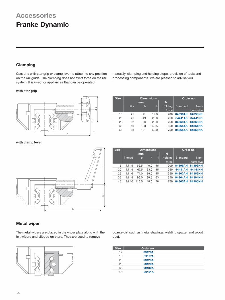
AccessoriesFranke Dynamic
Clamping
Cassette with star grip or clamp lever to attach to any position on the rail guide. The clamping does not exert force on the rail system. It is used for appliances that can be operated
with star grip
with clamp lever
Metal wiper
The metal wipers are placed in the wiper plate along with the felt wipers and clipped on there. They are used to remove
Size Dimensions Order no.mm N
Thread b h l Holding
force
Standard Non-
corrosive15 M 5 59.5 19.0 45 200 84396AH 84396NH20 M 5 67.5 23.0 45 250 84441AH 84441NH25 M 6 71.0 28.0 45 250 84363AH 84363NH35 M 8 96.0 38.5 63 350 84364AH 84364NH45 M 10 116.0 48.0 78 750 84365AH 84365NH
Size Dimensions Order no.mm N
Ø a b h Holding
force
Standard Non-
corrosive15 25 41 19.0 200 84396AK 84396NK20 25 49 23.0 250 84441AK 84441NK25 32 56 28.0 250 84363AK 84363NK35 50 83 38.5 350 84364AK 84364NK45 63 101 48.0 750 84365AK 84365NK
Size Order no.12 69126A15 69127A20 69128A25 69129A35 69130A45 69131A
manually, clamping and holding stops, provision of tools and processing components. We are pleased to advise you.
coarse dirt such as metal shavings, welding spatter and wood dust.
120

Size Dimensions Order no.mm
d D K L11 min. P12 M 5 12 8 15.0 6.0 63504A15 M 5 12 8 16.0 6.0 63504A20 M 5 12 8 17.0 6.0 63504A25 M 6 15 10 20.5 7.5 63505A35 M 8 19 13 26.5 9.5 63506A45 M 10 24 16 33.0 12.0 63507A
Size Dimensions Order no.mm
b h h1 k15 42 31.0 7.0 2.8 on request20 47 35.0 5.0 2.825 55 42.5 6.5 2.835 68 55.0 7.0 3.545 87 67.0 7.0 3.5
Size Dimensions Order no.mm
Cylinder screw DIN912 D12 M 3 6 87752A15 M 4 8 87753A20 M 5 10 87754A25 M 6 11 87755A35 M 8 15 87756A45 M 10 18 87757A
Bellows
The bellows for aluminium roller guides protect the rail system against coarse dirt. They are available in any lengths. The applied Velcro patches are used for attaching to the cassette and end plate. The cassette wipers are no longer needed.
Caps
In order to ensure that the wipers function ideally, the bores on the guide rails should be sealed using plastic caps enlosed
Stop screws
The stop screws are screwed into the thread (option) on the guide rails. A fitted rubber cap dampens impact. We deliver the drilling template displaced by one half bore gap for rail
with the delivery. You can order replacements individually. Material: POM wear-proof plastic, resistant to oil and ageing.
lengths with initial drilling dimensions below L11 min. Material: Chlorbutadiene rubber (Cr), black.
Material: synthetic fabric with one-sided polyurethane coating; temperature: contact heat +80 °C, radiant heat +120 °C.
Acc
esso
ries
121
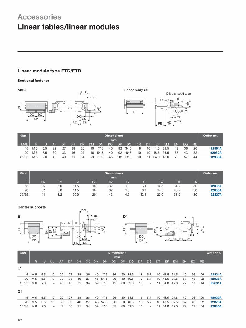
TL
RE TH
TE
TGTF
45° TCTBTA
TD
Drive-shaped tube
Linear module type FTC/FTD
Sectional fastener
Size Dimensions Order no.mm
MAE R U AF DF DH DK DM DN DO DP DQ DR DT EF EM EN EQ RE15 M 5 5.5 22 27 38 26 40 47.5 40 92 34.5 8 10 41.5 28.5 49 36 26 92981A20 M 5 5.5 30 33 46 27 46 54.5 40 92 40.5 10 10 48.5 35.5 57 43 32 92982A
25/35 M 6 7.0 48 40 71 34 59 67.0 45 112 52.0 10 11 64.0 45.0 72 57 44 92983A
Size Dimensions Order no.mm
T RE TA TB TC TD TE TF TG TH TL15 26 5.0 11.5 16 32 1.8 6.4 14.5 34.5 50 92835A20 32 5.0 11.5 16 32 1.8 6.4 14.5 40.5 50 92836A
25/35 44 8.2 20.0 20 43 4.5 12.3 20.0 58.0 80 92837A
Size Dimensions Order no.mm
R U UU AF DF DH DK DM DN DO DP DQ DR DS DT EF EM EN EQ RE
E1
15 M 5 5.5 10 22 27 38 26 40 47.5 36 50 34.5 8 5.7 10 41.5 28.5 49 36 26 92821A20 M 5 5.5 10 30 33 46 27 46 54.5 36 50 40.5 10 5.7 10 48.5 35.5 57 43 32 92826A
25/35 M 6 7.0 – 48 40 71 34 59 67.0 45 60 52.0 10 – 11 64.0 45.0 72 57 44 92831A
D1
15 M 5 5.5 10 22 27 38 26 40 47.5 36 50 34.5 8 5.7 10 41.5 28.5 49 36 26 92820A20 M 5 5.5 10 30 33 46 27 46 54.5 36 50 40.5 10 5.7 10 48.5 35.5 57 43 32 92825A
25/35 M 6 7.0 – 48 40 71 34 59 67.0 45 60 52.0 10 – 11 64.0 45.0 72 57 44 92830A
MAE T-assembly rail
AccessoriesLinear tables/linear modules
Center supports
E1 D1
122

L2
L3
L1
L
BD1
DØ10
HH
1
T1
T1
D3
B1
B2
Size Dimensions Order no.mm
M. channel. B B1 B2 D D1 H1 L L1 T120 50 83 96 10 5,5 10 25 12,5 4,6 34110
Size Dimensions Order no.mm
Groove key D3 H L2 L3 T20 M5 26 11,2 4 6,5 01199
Mounting channel
Lid fastener
RS RS ES ESOrder no.
Reed normally
closed
Reed normally
open
PNP normally
closed
PNP normally
openType: Type: Type: Type:RS-K RS-K ES-S ES-S
92841A 92842A 92844A 92845ARS-S RS-S
92847A 92843AConnection cable 5 m with cable coupling and open endFor signal transmitter type ES-S/RS-S 92846A
Size Max. torque
Dimensions Order no.
Nm mmDH Kbmax. LD LR1 LZR dR
15 60 55 16h7 5 <3000 LR1+112 30x4.0 92997A
20 60 55 22h7 5 <3000 LR1+126 30x4.0 92998A
35 160 65 32h7 5 <3000 LR1+167 35x4.0 92999A
Size Dimensions Order no.mm
E Ø U AB AC AD AE AF AG DG
A1
15 27 5,8 27 16 22 18 22 – 39 92810A20 36 6,6 36 18 26 20 30 – 50 92813A
C1
15 27 6,6 52 16,0 25 25 22 – 91 92978A20 36 9,0 64 18,0 25 25 30 – 114 92979A
25/35 70 9,0 48 12,5 30 30 48 128 174 92980A
End switch
Linear Module FTI
Intermediate drive shaft
Acc
esso
ries
123

124
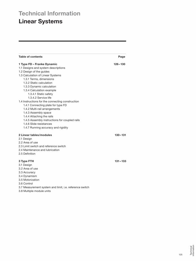
Technical InformationLinear Systems
Table of contents Page
1 Type FD – Franke Dynamic 126 – 1301.1 Designs and system descriptions1.2 Design of the guides1.3 Calculation of Linear Systems 1.3.1 Terms, dimensions 1.3.2 Static calculation 1.3.3 Dynamic calculation 1.3.4 Calculation example 1.3.4.1 Static safety 1.3.4.2 Service life1.4 Instructions for the connecting construction 1.4.1 Connecting plate for type FD 1.4.2 Multi-rail arrangements 1.4.3 Assembly space 1.4.4 Attaching the rails 1.4.5 Assembly instructions for coupled rails 1.4.6 Slide resistances 1.4.7 Running accuracy and rigidity
2 Linear tables/modules 130 – 1312.1 Design2.2 Area of use2.3 Limit switch and reference switch2.4 Maintenance and lubrication2.5 Definition
3 Type FTH 131 – 1333.1 Design3.2 Area of use3.3 Accuracy3.4 Dynamism3.5 Motorization3.6 Control3.7 Measurement system and limit, i.e. reference switch3.8 Multiple module units
Tech
nica
l in
form
atio
n
125

Technical InformationLinear Systems
Cassettes are mounted on rails and factory set free from clearance. An integrated clearance adjuster can be used downstream to align the aluminium roller guides to their respective load situation. The clearance setting is best determined by measuring the slide resistance in an unloaded state (see Diagram 2).
Diagram 2: Measure slide resistance
The screw connection on the cassette plate is loosened slightly to make the setting. After this the threaded pin integrated in the longer cassette side is reset. Turning the threaded pin displaces the roller shoe and hence increases or reduces preload
The setting values for the individual type are listed in Table 3.6 Slide resistances. Please find more precise instructions on fitting and setting the guides in the assembly instructions for the aluminium roller guides.
1.2 Design of the guidesThe following parameters are required to correctly design the guides:• Selection of arrangement• All prevalent forces/moments (dynamic/static),
(see Diagram 3)• Load type (resting, expanding, alternating)• Ambient influences (e.g. temperature, moisture) or special
operating conditions (e.g. clean room, vacuum)• Travel speed and acceleration• Stroke length• Target service life in km
All prevailing forces and moments must be within the speci-fied limits. The relevant data are found on the type pages.
Franke aluminium Linear Systems have base bodies made of high-strength anodized aluminium. Depending on their type, the rollers are mounted on needle or ball bearings and are made of roller bearing steel. Face plates made of plastic house the felt wipers that keep the guide system clean.
1 Type FD – Franke Dynamic
1.1 Designs and system descriptionAluminium roller guides by Franke are available as double rails with cassette or as a pair of single rails with a pair of roller shoes:
Double rail with cassetteBy standard, the design with double rail and cassette is a fully calibrated linear guide. The cassette and rail come with standard market connection bores.
Pair of single rails with pair of roller shoes (Diagram 1)The single rails with roller shoes are integral elements of the design, offering the benefit of variable guide width. The customer specifies the connecting plate. The cassette or the pair of roller shoes in standard type
Diagram 1: Pair of single rails and pair of roller shoes
FDA each run over four rollers mounted on needle bearings and arranged crosswise, fitted on raceways made of tough-but-flexible spring steel. Other types are available for special applications, among them non-corrosive raceways or individual customized versions.
The aluminium roller guides are lifetime lubricated. Travel speeds of 10 m/s and acceleration of 40 m/s² can be achieved. The operating temperature of the guides is between –20 °C and +100 °C. Franke is pleased to provide advice if you require solutions suitable for temperatures outside of the range specified above.
126

Fv
Fh
The equivalent load is the product of adding the individual external loads Fv and Fh.
Stat. equivalent load F0 = Fv + Fh
An off-center load Fa with a torsion moment M0 produces the following correlation:
F0 = F0 + C0 · Mx + C0 ·
Myz
M0cx M0cy,0cz
1.3.2.1 Recommended safetiesCondition Recommended safety Screw qual. 8.8Pressure load S > 1.3Tensile load S > 2.5Moment load S > 4.0
1.3.3 Dynamic calculationWe recommend a dynamic calculation of the load circum-stances if there is linear movement with v > 0.1 m/s.
Service life L = C · ∏ · DaF
(with P = 10/3 for the types FDA, FDC, FDD and FDE, and P = 3 for the types FDB, FDG, FDH)
The calculation is based on the following roller diameters Da:
The equivalent load is the product of adding the individual external loads Fv and Fh.
Dyn. equivalent load F = Fv + Fh
An off-center load Fa with a torsion moment M produces the following correlation:
F = Fa + C · MMdyn.
Size Diameter of rollers Da (mm)
12 11.015 12.520 15.525 19.035 27.545 34.5
Diagram 3: Arrangement of forces and moments
Recommended safeties (given Screw quality 8.8):• Pressure load: S > 1.2• Tensile load: S > 2.5• Moment load: S > 4.0
1.3 Calculation of Linear Systems
1.3.1 Terms, dimensionsC = dynamic rated load (N)C0 = static rated load (N)Da = diameter of rollers (mm)F = dynamic equivalent load (N)Fa = off-center load (N)F0 = static equivalent load (N)F1, F2, Fn = individual loads (N)Fh, Fv = horizontal force/vertical force (N)L = service life (km)M0cx, 0cy, 0cz = per. stat. moment rated load (Nm)Mcx, cy, cz = per. stat. or dyn. torsion moment (Nm)q1, q2 = time quotient for F1, F2 (%)S = safety
1.3.2 Static calculationA static calculation is sufficient with load at rest or in minimal linear motion up to v ≤ 0.1m/s. A linear guide with sufficient load capacity would be chosen once the recommended static safety S is reached.
Static safety S =C0
F0
( )p
Tech
nica
l in
form
atio
n
127

Gr. 12–25
Gr. 12–25
Gr. 35–45
Gr. 35–45
0.02
0.04 A
A
A
0.4
-0.1
b ±0.03
a -0.02-0.05
0.02
0.04
These calculations are based on a single one-rail arrangement of linear guides. We would be pleased to perform the calcula-tion for you when dealing with multi-rail arrangements or complicated load circumstances.
1.3.4 Calculation exampleFor your application you determined the load values Fv and Fh and would like to know whether an aluminium roller guide Franke Dynamic type FDA in size 25 will provide sufficient safety and service life.
Your values (examples): Fv = 2000 NFh = 400NF = Fv + Fh = 2400 N
Franke Dynamic FDA size 25:C = 9000 NC0 = 10100 NDa = 19 mm
1.3.4.1 Static safetyIn your application there will be an overhead load. Please find a recommended safety of > 2.5 in Table 2.1.
S =C0 =
10100 N= 4.2
F0 2400 N
The calculation confirms adequate safety.
1.3.4.2 Service life
L = C · ∏ · Da = 9000 · 3,14 · 19 = 4890F 2400
The service life is 4890 kilometers.
1.4 Instructions for the connecting construction
1.4.1 Connecting plate for type FDWhen using single rails and roller shoes please also use a connecting plate (additional design). The roller shoes and the connecting plate form the runner.
Instruction on designing the connecting plate for the runner:The roller shoes come with centering grooves to facilitate adjustment during assembly. To do this you attach a centering web to the connecting plate (Diagram 4). The dimensions for producing the centering web are listed in Table 1. All other dimensions, tolerances and accuracies of the guides are listed on the respective pages.
Technical InformationLinear Systems
Diagram 4: Centering web
Table 1: Dimensions of centering web
1.4.2 Multi-rail arrangementsIf there is a multi-rail arrangement it is recommended to define a fixed and a loose bearing side on the runner plate. This is the best method to compensate tolerances between the rails.
For instance the loose bearing side can be designed with a catch and a stay rod. The fixed bearing side assumes the guide function, while the loose bearing side compensates parallel adjustment and height tolerances. It is recommended to design the drive in the immediate proximity of the guide side, as it is what absorbs the drive moments.
1.4.3 Assembly space The input and connecting surfaces have substantial influence on the function and accuracy of the guide. Inaccuracies may accumulate on top of the running accuracy of the guide system. An exact parallel and height adjustment is necessary if there is a double-track arrangement, for instance. The accuracy of the screw-on and connection surfaces for the rails as specified in Table 2 must be adhered to in order to guarantee running accuracy of the guide:
Table 2: Accuracy of input and connecting surfaces
Size a bmm mm
12 4.5 9.615 5.0 12.620 7.5 16.125 10.5 17.635 12.5 26.145 15.5 31.1
Size 12-20 25-45mm mm
Max. tolerance for parallel run 0.03/m 0.05/mMax. evenness of screw-on surface 0.05/m 0.10/m
( )103( )
p
128

Bearing shoulder (marking groove)
Bearing and contact table load direction
Bearing surface load direction
Screwed ScrewedScrewed and dowelled
The rails are labelled additionally with a marking groove below the lower edge of the rail; it must always be on the same side. The rails must be aligned without a gap. To do this please use the suitable auxiliary cylinder (Diagram 6). Dimensions for aligning the auxiliary cylinder are found in Table 3. The cylinders are inserted into the raceways at the separating point of the rails and loaded using a suitable device. The matching tightening torques for the screw connections in question are listed in Table 4.
Table 3: Dimensions of auxiliary cylinder
Table 4: Tightening torques for screw connections
1.4.6 Slide resistances*
* Without wipers
Size Auxiliary cylinder mm
12 1115 1120 1425 1635 2745 35
Screw Tightening torque M 3 1.1 M 4 2.5 M 5 5.0 M 6 8.5 M 8 21.0 M 10 41.0 M 12 71.0
Size Slide resistanceN with
FDA FDB FDG FDC FDD FDE FDH wipers12 Min. 1,0 0,15 0,2 1,0 – 0,5 – +3
Max. 1,5 0,30 0,3 2,0 – 2,0 – +315 Min. 0,5 0,20 0,2 0,5 – 0,8 – +3
Max. 2,0 0,40 0,3 2,0 – 2,0 – +320 Min. 1,5 0,50 0,5 1,5 – 1,0 – +4
Max. 2,5 0,90 0,9 2,5 – 2,5 – +425 Min. 1,5 0,40 1,0 1,5 1,5 1,5 2,5 +5
Max. 3,0 0,80 1,5 3,0 3,0 3,0 5,0 +535 Min. 2,0 1,00 3,0 2,0 – 2,0 4,0 +7
Max. 4,0 1,50 4,0 4,0 – 4,0 6,0 +745 Min. 5,0 2,00 3,0 5,0 – 5,0 5,0 +8
Max. 8,0 3,00 4,0 8,0 – 8,0 8,0 +8
1.4.4 Attaching the rails Use a ruler or a locating shoulder to align of the rails. Depending on the type of load, the guide rails should be1. screwed on or2. screwed on and dowelled or3. applied against a locating shoulder and screwed on
(Table 5).
Diagram 5: Attaching the rails
The connections between the guide elements and the connecting construction influence the load capacity of the guide. Screws in quality 8.8 with washers DIN 433 are used to make the attachment to the connecting construction.
1.4.5 Assembly instruction for coupled railsRails above a length of 4000 mm are coupled according to the Franke standard. Separation according to the Franke standard guarantees a constant, even drilling pattern and an ideal use of the rail length. Separations according to customer specifi-cations are also possible.
Coupled rails are specifically matched. This is why the rails have a sequential product number (e.g. A/1-1/1-2/2-2/E) to ensure correct assembly.
Diagram 6: Coupled rails/auxiliary cylinder
Tech
nica
l in
form
atio
n
129

0 100 200 300 400 500 600 700 800 900 Nm
Degree1.0
0.9
0.8
0.7
0.6
0.5
0.4
0.3
0.2
0.1
0
Rigidity around the X-module: FDA, FDC, FDD, FDE, FDH
12
15
20 2535
45
0 10 20 30 40 50 60 70 80 90 Nm
0.150
0.135
0.120
0.105
0.090
0.075
0.060
0.045
0.030
0.015
0
Rigidity around the X-module: FDB, FDG
12
1520
25
35
45
Degree
Running accuracy Franke Dynamic over 1 m
0 12 15 20 25 35 45 Size
µm100
90
80
70
60
50
40
30
20
10
0
FDB, FDG
FDA, FDC,FDD, FDE
FDH
Technical InformationLinear Systems
1.4.7 Running accuracy and rigidity 2 Linear tables/modules
2.1 Design Uses of Franke linear tables include automation tasks in measurement and testing or to rationalize handling and assembly. The selection ranges from strokes larger than 100 mm to 7000 mm; there are spindle and belt drives. The lightweight aluminium construction, in connection with the integrated Franke guide system, permits high load ratings and moment loads. Please find precise technical data on this in the respective catalogue pages.
2.2 Area of useWe recommend using Franke Linear Systems with the safety S ≥ 3 for simple loads without acceleration and moment loads. A safety of S ≥ 6 should be used for dynamic moments. The mounting position is infinitely variable; we recommend an end stop or a brake for vertical operation.
The positioning accuracy of the Linear Systems type FTB is ±0.025 / 300 mm (IT7) as defined in the spindle pitch accuracy. Other accuracies are available on request. Repeatability is ≤ 0.01 mm. Running accuracy of the linear tables FTB is 0.02 / 300 mm.Franke rotary tables can be used in operating temperatures from –20 °C to +80 °C. The Linear Systems FTD 15 – 35 are suitable for continuous operation in temperatures of –30 °C to +80 °C. Please contact us if you wish to operate in a different temperature range.
2.3 Limit switch and reference switch • Reference switch: Franke Linear Systems in series FTB are
fitted with inductive proximity switches that are set to stroke end position. On request another proximity switch can be fitted as a reference switch. The linear modules FTC and FTD have the option of attaching infinitely adjustable limit switches to the outside. By standard, Franke Linear Systems are fitted with inductive limit and reference switches PNP-nc 10-30VDC. PNP-no, NPN-no and NPN-nc switches are available on request. Fitting or installing a length measurement system with sinus or square-wave signal is possible on request. Rotary encoders can be fitted to the motor.
• Multi-module units: Franke Linear Systems can be com-bined to produce multi-module units. The required angle and adapter plates are selected to meet your requirements. We deliver fully fitted units, wired and aligned, with addition-al accessories on request.
• Motorization: A large variety of stepper or servo motors can be fitted to the Linear Systems. Connecting flanges and
130

couplings are modified accordingly. We can also accommo-date customer motors.
• Motor deflection, transmission: By standard, the motor is mounted in the extension of the stroke module. Motor deflection via toothed belt or angled gears can be fitted to suit special uses, e.g. in cramped spaces.
We are pleased to advise you here, also.
2.4 Maintenance and lubricationFranke Linear Systems are low-maintenance and have factory-fitted lifetime lubrication. Relubrication is not neces-sary, apart from the ball screw. Relubrication may be neces-sary – depending on the use – resulting from leakage of grease via the spindle shaft. We recommend relubrication with approx. 1 – 2 g grease in intervals of approx. 700 operating hours. If necessary you should clean the insides and the guide tracks and coat them with grease.
Fully synthetic lubricants are best suited for long.term lubrication, In its factory Franke uses the fully synthetic, special grease ISOFLEX TOPAS NCA52 (made by Klüber). We recommend high-quality lithium soap grease on mineral oil basis as an alternative lubricant. If you intend to mix lubricants you must make sure that the types are compatible in terms of base oil type, thickener, base oil viscosity and NLGI class. Please consult with the lubricant manufacturer for extreme conditions and extraordinary operating circumstances (vacuum, radiation, high temperature).
2.5 Definitions • Running accuracy describes the greatest possible deviation
between any given point on the moved table surface from the ideal lines when travelling the entire stroke distance (provided the substructure is even).
• Positioning accuracy is the greatest possible deviation from reaching a predefined point traveled to from a previously defined zero point.
• Repeatability is the greatest possible deviation from reaching a previously defined point on multiple instances. The measurement system used defines the degree of accuracy.
• Discrimination is the smallest possible travel distance. It is dependent on the spindle pitch, the transmission, the step angle and the classification within the measurement system. Discrimination is used to neutralize faults in positioning or repetition. It must therefore always be higher than the permissible positioning accuracy.
Please observe our assembly and maintenance instruc-tions for each item.
3 Type FTH
3.1 Design Franke linear motor modules FTH Drive are suitable for tasks in measurement and testing, also in handling and assembly. Strokes from 200 mm to 5300 mm are available. Integrated linear motors provide the drive. The lightweight aluminium construction, based on the Franke guide system, permits high load ratings and moment loads.
3.2 Area of useWe recommend using the safety S ≥ 3 for simple loads without acceleration and moment loads. A safety of S ≥ 6 should be achieved for dynamic moments. The mounting position is infinitely variable; we recommend an end stop or a brake for vertical operation.
Franke linear motor modules FTH Drive can be used in operating temperatures from –20 °C to +80 °C. Other temper-ature ranges on request.
3.3 AccuracyThe positioning accuracy is ±0.01 mm/m and is dependent on the measurement system used. Other accuracies are available on request. The repeatability is ≤ 0.02 mm. The running accuracy is 0.04 mm/m.
3.4 DynamismFranke linear motor modules FTH Drive can achieve the values listed in the diagrams (page 133). These are approximate values that are based on a horizontal feed movement in trapezoidal/delta operation. We are pleased to define the matching components for your application.
3.5 Motorization The linear motor modules FTH Drive are driven by linear servo motors without mechanical drive components. The linear motor consists of a slide part and a guide part. The slide part houses the windings, the position recorder and the tempera-ture gage. The drive magnets are found in the guide part.
The linear motors used are characterized by extremely high performance density (maximum dynamism with smallest possible space) and hence permit acceleration of up to 100 m/s2 and travel speeds of up to 9 m/s.
Tech
nica
l in
form
atio
n
131

w
d
h
Technical InformationLinear Systems
3.6 Control
We recommend a servo amplifier S700 by the provider Kollmorgen to operate the linear motor modules FTH Drive. The S700 offers numerous special features such as the free graphic Windows® software to commission the servo amplifi-er. The auto-tuning function additionally facilitates commis-sioning. A safe torque off (STO) is fitted as standard. The S700 can load many different return systems and can evaluate up to three positioning informations sets at once.
Our team of consultants will provide you with additional information, or access information on the Internet under www.kollmorgen.com.
3.7 Measurement system and limit, i.e. reference switchBy standard, Franke linear motor modules are fitted with an integrated, magnetic length measurement system. The positioning accuracy is ± 10 µm with discrimination of ± 1 µm. Absolute measurement systems are available optionally.
Inductive proximity switches, infinitely positionable in the guide profile, are available to record end positions or refer-ence positions.
3.8 Multiple module units Linear motor modules type FTH Drive can be combined to form multi-module units. The required angle and adapter plates are selected to meet your requirements. We deliver fully fitted units, wired and aligned, with additional accessories on request.
Please observe our assembly and maintenance instruc-tions for each item.
Dimensions mm
H (incl. fan) B L (incl. plug)345 70 243
132

3000
2500
2000
1500
1000
500
0
0 300 400 500 600 700 800 900 1000
mm Type FTH25A
ms
Delta operation
1 kg
5 kg
10 kg
15 kg
3000
2500
2000
1500
1000
500
0
0 300 400 500 600 700 800 900 1000
mm
ms
Type FTH35A Delta operation1 kg
5 kg
10 kg
15 kg
20 kg
3000
2500
2000
1500
1000
500
0
0 300 400 500 600 700 800 900 1000
mm
ms
Type FTH25B Delta operation
1 kg
5 kg
10 kg
15 kg
3000
2500
2000
1500
1000
500
0
0 300 400 500 600 700 800 900 1000
mm
ms
Type FTH35B Delta operation
20 kg10 kg
30 kg
40 kg
1 kg
0 1.185 2.192 3.42 4.68 m
m/s10
8
6
4
2
0
Type FTH25A Acceleration to Vmax 9 m/s1 kg
34 m/s25 kg
18.5 m/s210 kg
11.8 m/s215 kg
8.7 m/s2
0 0.68 0.926 1.19 1.471 1.667 m
m/s7
6
5
4
3
2
1
0
Type FTH35A Acceleration to Vmax 6 m/s
1 kg38 m/s2
5 kg27 m/s2
10 kg21 m/s2
15 kg17 m/s2
20 kg15 m/s2
0 0.232 0.673 0.985 1.293 m
m/s5
4
3
2
1
0
Type FTH25B Acceleration to Vmax 4.5 m/s1 kg
43.7 m/s25 kg
15.1 m/s210 kg
10.3 m/s215 kg
7.8 m/s2
0 0.625 0.833 1.111 1.389 1.613 m
m/s7
6
5
4
3
2
1
0
Type FTH35B Acceleration to Vmax 6 m/s
30 kg18 m/s2
1 kg40 m/s2
10 kg30 m/s2
20 kg22.5 m/s2
40 kg15.5 m/s2
Tech
nica
l in
form
atio
n
133

Franke GmbHObere Bahnstraße 6473431 Aalen, GermanyTel. +49 7361 920-0Fax +49 7361 [email protected]
www.franke-gmbh.com
Support and consulting
GK
_e_2
016
Cha
nges
and
err
ors
rese
rved
.
Please find your contact person at Franke, on hand to assist if you have any question or need advice.