rolling-element bearings · 2018-07-04 · 203 rolling-element bearings in rolling-element bearings...
TRANSCRIPT

203
Rolling-Element Bearings
In rolling-element bearings the shaft and outer members are separated by
balls or rollers, and thus rolling friction is substituted for sliding friction.
Examples are shown in Figures (1) through (8). Since the contact areas
are small and the stresses high, the loaded parts of rolling-element
bearings are normally made of hard, high-strength materials, superior to
those of the shaft and outer member. These parts include inner and outer
rings and the balls or rollers. An additional component of the bearing is
usually a retainer or separator, which keeps the balls or rollers evenly,
spaced and separated. Both sliding and rolling-element bearings have
their places in modern machinery. A major advantage of rolling-
element bearings is low starting friction. Sliding bearings can achieve
comparably low friction only with full-film lubrication (complete surface
separation).

204
Fig.(1) Radial ball bearing
Fig.(2) Relative proportions of bearings of different series.
Fig.(3)

205
Fig.(4) Double row ball bearing
Fig.(5) Thrust Bearing
(a) Single-row (b) Double-row (c) Four-row
Fig.(6)

206
(a) Drawn cup caged (b) Full complement aircraft
(c)Full-complement drawn-cup (d) Thrust
Fig.(7)
(a) Pillow block mounting (b) Flange bearing
Fig.(8) Sample special bearings

202
Manufacturing tolerances are extremely critical. In the case of ball
bearings, the Annular Bearing Engineers’ Committee (ABEC) of the
Anti-Friction Bearing Manufacturers Association (AFBMA) has
established four primary grades of precision, designated ABEC 1, 5, 7,
and 9. ABEC 1 is the standard grade and is adequate for most normal
applications. The other grades have progressively finer tolerances. For
example, tolerances on bearing bores between 35 and 50 mm range from
+0.0000 in. to -0.0005 in. for ABEC grade 1 to +0.00000 in. to -0.00010
in. for ABEC grade 9. Tolerances on other dimensions are comparable.
Fitting of Rolling-Element Bearings
Normal practice is to fit the stationary ring with a “slip” or “tap” fit and
the rotating ring with enough interference to prevent relative motion
during operation. Recommended fits depend on bearing type, size, and
tolerance grade. Proper fits and tolerances are influenced by the radial
stiffness of the shaft and housing, and sometimes by thermal expansion.
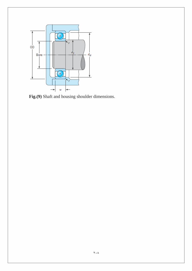
“Catalogue Information” for Rolling-Element Bearings
Bearing manufacturers’ catalogues identify bearings by number, give
complete dimensional information, list rated load capacities, and furnish
details concerning mounting, lubrication, and operation. Dimensions of
the more common series of radial ball bearings, angular ball bearings, and
cylindrical roller bearings are given in Table (1) and illustrated in
Figure(9). For bearings of these types having bores of 20 mm and
larger, the bore diameter is five times the last two digits in the
bearing number. For example, No. L08 is an extra-light series
bearing with a 40-mm bore, No. 316 is a medium series with an 80-
mm bore, and so on. Actual bearing numbers include additional letters
and numbers to provide more information. Many bearing varieties are
also available in inch series.
202
Fig.(9) Shaft and housing shoulder dimensions.
202
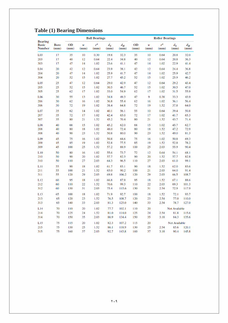
Table (1) Bearing Dimensions

210
Table (2) lists rated load capacities, C. These values correspond to a
constant radial load that 90 percent of a group of presumably identical
bearings can endure for 9 * 107 revolutions (as 3000 hours of 500-rpm
operation) without the onset of surface fatigue failures.
Caution: Rated capacities given by different bearing manufacturers are
not always directly comparable. The basis for ratings must always be
checked.

211
Table(2) Bearing Rated Capacities, C, for LR =90×106 Revolution Life
with 90 Percent Reliability

212
Life Requirement
Bearing applications usually require lives different from that used for the
catalogue rating. Palmgren’s determined that ball-bearing life varies
inversely with approximately the third power of the load. Later
studies have indicated that this exponent ranges between 3 and 4 for
various rolling-element bearings. Many manufacturers retain
Palmgren’s exponent of 3 for ball bearings and use
for roller
bearings. The exponent
for both bearing types is used. Thus
(1)
(2)
where
C = rated capacity (as from Table 2) and Creq = the required value of C
for the application
LR = life corresponding to rated capacity (i.e., 9 * 107 revolutions)
Fr = radial load involved in the application
L = life corresponding to radial load Fr , or life required by the application
Thus doubling the load on a bearing reduces its life by a factor of about
10. Different manufacturers’ catalogues use different values of (LR).
Some use LR = 106 revolutions.
Reliability Requirement:
The standard life is commonly designated as the L10 life (sometimes as
the B10 life). Since this life corresponds to 10 percent failures, it also
means that this is the life for which 90 percent have not failed, and
213
corresponds to 90 percent reliability. Thus, the life for 50 percent
reliability is about five times the life for 90 percent reliability.
The rated bearing life for any given reliability (greater than 90 percent) is
thus the product, KrLR. Incorporating this factor into Eq. (1) gives:
(3)
(4)
Influence of Axial Loading
Cylindrical roller bearings are very limited in their thrust capacity
because axial loads produce sliding friction at the roller ends. Even so,
when these bearings are properly aligned, radially loaded, and oil-
lubricated, they can carry thrust loads up to 20 percent of their rated
radial capacities. This enables pairs of cylindrical roller bearings to
support shafts subjected to light thrust, as by spur gears or chain
sprockets. Tapered roller bearings can, of course, carry substantial
thrust as well as radial loads.
For ball bearings, any combination of radial load (Fr) and thrust load (Ft)
results in approximately the same life as does a pure radial equivalent
load, Fe, calculated from the equations that follow. Load angle α is
defined in Figure (3b). Radial bearings have a zero load angle (α=0o).
Standard values for angular ball bearings are 15°, 25°, and 35°.
For radial bearings(α=0o) the equivalent radial load can be calculated as:
⁄
⁄ (
) (5)

214
⁄
α=25o (angular ball bearing)
⁄
⁄ (
) (6)
⁄
Shock Loading:
The standard bearing rated capacity is for the condition of uniform load
without shock. This desirable condition may prevail for some applications
(such as bearings on the motor and rotor shafts of a belt-driven electric
blower), but other applications have various degrees of shock loading.
This has the effect of increasing the nominal load by an application factor
Ka. Table (3) gives representative sample values.
Table(3) Application Factors Ka
Substituting Fe for Fr and adding Ka modifies Eq.(3) and Eq.(4) to give
(7)
(8)

215
When the preceding equations are used, the question is what life, L
should be required. Table (4) may be used as a guide when more specific
information is not available.
Table (4) Representative Bearing Design Life
Ex (1):
Select a ball bearing for an industrial machine press fit onto a shaft and
intended for continuous one-shift (8-hour day) operation at 1800 rpm.
Radial and thrust loads are 1.2 and 1.5 kN, respectively, with light-to-
moderate impact.
Fig(10) Radial- and angular-contact ball bearings
Solution
From Eqs. (5) and (6), the equivalent radial load for radial and angular
ball bearings, respectively,

216
Since
0
So that, use equation (5) to calculate the equivalent load
(
)
For angular ball bearing (α=25o) use equation (6)
[ (
)]
(angular bearing)
From table (3) Ka=1.5
From table (4) for a machine with 8-hour service, every working day
Ka=( 20 to30)×103 hours choose Ka=30000hr
The life L can be calculated as
L=1800×30000×60=3240×106 rev
For standard 90 percent reliability (Kr = 1), and for LR = 90 * 106 rev (for
use with Table (2)).
Calculate the equivalent radial capacity of the bearing as:
With the above values of load rating inter table (2) to define the suitable
bore diameter for each group.

212
For radial bearing ( Creq=10.55kN)
For series L the bore diameter is 70mm
For series 200 the bore diameter is 55
For series 300 the bore diameter is 35
Now inter table (1) with the above values of diameters (for each group)
For series L : Bearing L14 is suitable
For series 200: Bearing 211 is suitable
For series 300: Bearing 307 is suitable
Repeat the above procedure for angular contact bearing with α=25o
(C=7.91kN) to get:
For series L the bore diameter is 55mm
For series 200 the bore diameter is 35
For series 300 the bore diameter is 30
Now inter table one with the above values of diameters (for each group)
For series L : Bearing L11 is suitable
For series 200: Bearing 207 is suitable
For series 300: Bearing 306 is suitable
Comment: Other factors being equal, the final selection would be made
on the basis of cost of the total installation, including shaft and housing.
Shaft size should be sufficient to limit bearing misalignment to no more
than 15.
Ex (2):
Suppose that radial-contact bearing 211 (C = 12.0 kN) is selected for the
application in example (1). (a) Estimate the life of this bearing, with 90
percent reliability. (b) Estimate its reliability for 30,000-hour life.
Solution
(a)L = KrLR(C/FeKa)3.33
L = (1)(90×106)(12/2.4×1.5)
3.33=495,939,5358rev
Convert the revolutions to hours as follows

212
(b)
Life in revs=30000×1800×60=3240×106 rev
To evaluate Kr
3240 * 106 = Kr(90 * 10
6)(12.0/3.6)
3.33
Kr = 0.65
Use the following chart to determine the required reliability
Fig(11) Reliability chart
For Kr=0.65 the reliability of the bearing is 95%

212
Mounting and Closure of Rolling Bearings
Rolling-element bearings are generally mounted with the rotating inner or
outer ring with a press fit. Bearing manufacturers’ literature contains
extensive information and illustrations on mountings. The basic principle
of mounting ball bearings properly is discussed her in. Figure (12) shows
a common method of mounting, where the inner rings are backed up
against the shaft shoulders and held in position by round nuts threaded
into the shaft. As noted, the outer ring of the left-hand bearing is backed
up against a housing shoulder and retained in position, but the outer ring
of the right-hand bearing floats in the housing. This allows the outer ring
to slide both ways in its mounting to avoid thermal-expansion-induced
axial forces on the bearings, which would seriously shorten their life. An
alternative bearing mounting is illustrated in Figure (13). Here, the inner
ring is backed up against the shaft shoulder, as before, however, no
retaining device is needed; threads are eliminated. With this assembly, the
outer rings of both bearings are completely retained. As a result, accurate
dimensions in axial direction or the use of adjusting devices is required.
Fig.(12) A common bearing mounting

220
Fig.(13) An alternative bearing mounting. (The outer rings of both
bearings are held in position by devices (not shown).
Fig.(14) Bearings mounted so that left bearing takes thrust in both
directions.

221
Ex: A transmission shaft, transmitting 8kW of power at 400rpm from a
bevel gear G1 to a helical gear G2 and mounted on two ball bearings B1
and B2 is shown in fig.(15 -a ). The gear tooth forces on the helical gear
act at a pitch circle radius of 55mm, while those on the bevel gear can be
assumed to act at the large end of the tooth at a radius of 50mm. The
diameter of the journal at the bearings B1 and B2 is 40mm. Bearings B1
and B2 are identical and press fitted on the shaft and intended for
continuous on shift (8hours day) operation with light to moderate impact.
The thrust force due to bevel and helical gears is taken by the bearing B2.
Select suitable ball bearing for this application.
Fig.(15)
Solution:

222
Considering forces in the vertical plane, taking moments about the
bearing B1,
3473(150)+439(100)-1319(50) –Rv2 (300)=0
Or Rv2 =1663N
Considering equilibrium of vertical forces
3473-Rv1 -1663-439=0
Or Rv1=1371N
Considering forces in the horizontal plane and taking moments about the
bearing B1.
3820(100)+1265(150)+1475(55)-RH2(300)=0
Or RH2=2176.25N
Considering equilibrium of horizontal forces
2176.25+3820-1265-RH1=0
Or RH1=4731.25N
The radial forces acting on the bearing are as follows
Fr1=[(Rv1)2+(RH1)
2]
0.5=[(1371)
2+(4731.25)
2]
0.5=4926N
Fr2=[(Rv2)2+(RH2)
2]
0.5=[(1663)
2+(2176.25)
2]
0.5=2739N
Fa=Ft=1319+1475=2794N
Both types, angular type(α=25o) and radial ball bearings may be selected
as follow:
At B2:
Since n=400rpm, for a machine with 8hrs service every day the bearing
design life is 30000hr (from table4)
L=400×30000×60=720×106 rev
Ft/Fr=2794/2739=1.02
0
(
)

223
For 90% reliability Kr=1
From table (3) the application factor Ka for light to moderate impact is
1.5
LR=90×106 rev.
Enter table with this value of Creq to get
Loo 200 300
Bore 75 60 45
Bearing type(table 1) L15 212 309
For Bearing at B1
Since there is no axial force at this bearing.
Fe= Fr1=4926N or 4.926kN
From table (2)
Loo 200 300
Bore(mm) 80 65 45
Bearing type L16 213 309
Ex:
The second shaft on a parallel-shaft 25-hp foundry crane speed reducer
contains a helical gear with a pitch diameter of 8.08 in. Helical gears

224
transmit components of force in the tangential, radial, and axial
directions. The components of the gear force transmitted to the second
shaft are shown in Fig. (16) at point A. The bearing reactions at C and D,
assuming simple-supports, are also shown. A ball bearing is to be
selected for location C to accept the thrust, and a cylindrical roller
bearing is to be utilized at location D. The life goal of the speed reducer is
10 kh, with a reliability factor for the ensemble of all four bearings (both
shafts) to equal 1 (90% reliability)with light to moderate impact.
(a) Select the roller bearing for location D.
(b) Select the ball bearing (angular contact) for location C, assuming the
inner ring rotates.
Fig.(16)
Solution
(a) For roller bearing at D
T= 595×4.04=2403 lb.in
Power= (T×n)/63000

225
n= 63000×power(hp)/T
n=63000×25/2403=655.42rpm
L= 655.42×10000×60=393.252×10⁶ rev.
Fr=[297.52+106
2]
0.5=316.16lb or 316.16×4.44=1403.13N= 1.403kN
Since there is no axial force at D
Fe=Fr
Series 1000 1200 1300
Bore(table 2) 20 17 17
Bearing Type Lo4 203 203
(b) Selection of ball bearing
1. Radial Ball bearing
Fr=[3562+297.5
2]
0.5=463.94lb
0.35<Ft/Fr=344/463.62=0.74<10
(
)
Or 664.851×4.44=2951.93N= 2.951kN
Kr=1, Ka(table 3)=1.5
XL 200 300
Bore(table 2) 55 35 30
Bearing type(table1) L11 207 306

226
2. For angular contact withα=25o
[ (
)]
487.168 lb
Or 487.168×4.44=2163N=2.163kN
Series L00 200 300
Bore(table 2) 45 30 20
Bearing type(table1) L09 206 304

222
Rolling Bearing Life
Definitions:
We note that bearing life is defined as the number of revolutions
or hours at some uniform speed at which the bearing operates until
fatigue failure.
Rating life L10 refers to the number of revolutions (or hours at a uniform
speed) that 90% of a group of identical roller bearings will complete or
exceed before the first evidence of
fatigue develops. The term minimum life is also used to denote the rating
life.
Median life refers to the life that 50% of the group of bearings would
complete or exceed. Test results show that the median life is about five
times the L10 life.
Alternative method to calculate equivalent Radial Load
Catalog ratings are based only on the radial load. However, with the
exception of thrust bearings, bearings are usually operated with some
combined radial and axial loads. It is then necessary to define an
equivalent radial load that has the same effect on bearing life as the
applied loading. For rolling bearings, the maximum of the values of these
two equations is recommended:
P = XVFr +YFa (1)
P = VFr (2)
where
P = the equivalent radial load
Fr = the applied radial load
Fa = the applied axial load (thrust)
V = a rotational factor = 1.0 for inner-ring rotation
1.2 for outer-ring rotation
X = a radial factor

222
Y = a thrust factor
For deep-groove (single-row and double-row) and angular-contact ball
bearings, the values of X and Y are given in Tables (5) and (6). Straight
cylindrical roller bearings are very limited in their thrust capacity because
axial loads produce sliding friction at the roller ends. So, the equivalent
load for these bearings can also be estimated using Equation (2).
Table(5) Factors for deep- groove ball bearings
Table(6) Factors commonly used for angular contact bearings
222
Equivalent Shock Loading
Some applications have various degrees of shock loading, which has the
effect of increasing the equivalent radial load. Therefore, a shock or
service factor, Ks, can be substituted into Equations (1) and (2) to account
for any shock and impact conditions to which the bearing may be
subjected. In so doing, the equivalent radial load becomes the larger of
the values given by the two equations:
P = Ks (XVFr +YFa ) (3)
P = KsVFr (4)
Selection of Rolling Bearings
Extensive testing of rolling bearings and subsequent statistical analysis
has shown that load and life of a bearing are related statistically. This
relationship can be expressed as
(5)
where
L10 = the rating life, in 106 revolution
C = the basic load rating (from Tables (7) and (8))
P = the equivalent radial load (equations 1 and 2)
a = 3 for ball bearings
10/3 for roller bearings

230
Table(7) Dimensions and Basic load Rating for 02 series Ball Bearing
Table(8) Dimensions and Basic load Rating for straight cylindrical
Bearing
231
Alternatively, the foregoing equation may be written in the following
form:
(6)
where
L10 represents the rating life, in h
n is the rotational speed, in rpm
When two groups of identical bearings are run with different loads P1 and
P2, the ratio of their rating lives L'10 and L
''10, by Equation(5), is
(7)
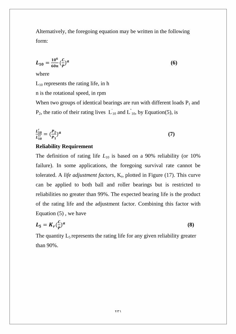
Reliability Requirement
The definition of rating life L10 is based on a 90% reliability (or 10%
failure). In some applications, the foregoing survival rate cannot be
tolerated. A life adjustment factors, Kr, plotted in Figure (17). This curve
can be applied to both ball and roller bearings but is restricted to
reliabilities no greater than 99%. The expected bearing life is the product
of the rating life and the adjustment factor. Combining this factor with
Equation (5) , we have
(8)
The quantity L5 represents the rating life for any given reliability greater
than 90%.
232
Fig.(17) Reliability factor Kr.
For reference, Table (9) may be used to Represent Rolling Bearing
Design Lives.
Table(9) Representative Rolling Bearing Design Lives
Example: Median Life of a Deep-Groove Ball Bearing
A 50 mm bore (02-series) deep-groove ball bearing, carries
a combined load of 9 kN radially and 6 kN axially at 1200 rpm. Calculate
a. The equivalent radial load
b. The median life in hours
233
The inner ring rotates and the load is steady.
Solution
Referring to Table (7) for a 50 mm bore bearing, C = 35.1 kN and Cs =
19.6 kN.
a. To obtain the values of the radial load factors X and Y, it is
necessary to obtain
We find from Table (5) that Fa/VFr > e: X = 0.56 and Y = 1.13 by
interpolation. Applying Equation (1),
P=XVFr+YFa=(0.56)(1)(9)+(1.13)(6)=11.82kN
Through the use of Equation (2), P = VFr = 1(9) = 9 kN.
b. Since 11.95 > 9 kN, the larger value is used for life calculation.
The rating life, from Equation (5), is
Or life in hours can be calculated:
(
) (
)
The median life is therefore 5L10 = 5×364=1820 h.
Ex: Determine the expected life of the bearing in the previous example if
only a 6% probability of failure can be permitted.

234
Solution
From Figure (17), for a reliability of 94%, Kr = 0.7. Using Equation (8),
the expected rating life is
Comment: To improve the reliability of the bearing in the previous
example from 90% to 94%, a reduction of median life from 1820 h to
5L5 =1274 h is required.