processing guidelines tuball matrix 601 602 613 beta …
TRANSCRIPT

PROCESSING GUIDELINES
TUBALL™ MATRIX 601, 602 and 613 beta for Liquid Silicones
Contents 1. DILUTION PRINCIPLES ................................................................................................. 2 2. DILUTION PROCEDURE IN LOW-VISCOSITY SILICONES (<50,000 mPa·s) .............. 4 High-speed mixer ................................................................................................................ 5 3. DILUTION PROCEDURE IN HIGH-VISCOSITY SILICONES (>200,000 mPa·s) ........... 8 Three-roll mill ...................................................................................................................... 8 4. EXAMPLES OF CALCULATIONS AND COMPOUNDING ........................................... 11 5. DISPERSION QUALITY CONTROL ............................................................................. 12 Visual control of the quality of MATRIX dispersion in silicone ........................................... 12 Measurement of resistivity ................................................................................................ 13 6. TROUBLESHOOTING .................................................................................................. 16
V05_202110041004

2 V05_202110041004
1. DILUTION PRINCIPLES Uniform distribution of TUBALL™ MATRIX in the silicone plays a key role in enhancing the electrical conductivity of the final compound. In order to obtain a high-quality TUBALL™ MATRIX dispersion, OCSiAl recommends that close attention be paid to the dilution procedure.
• The resistivity level achieved will depend on the loading of TUBALL™ MATRIX. The target dosage of TUBALL™ MATRIX refers to the loading in the whole silicone formulation by weight.
• The mixing time, number of mixing cycles and mixing speed may need to be adapted for different machinery size/type to obtain a final mixture that is homogeneous.
• The dilution ratio depends on the required level of resistivity and the loading of TUBALL™ MATRIX.
Figure 1. Volume resistivity of 30 Hardness LSR silicone (Silopren LSR 2030,
Viscosity 350,000 mPa*s) with TUBALL™ MATRIX 601, 602 and 613 beta in the range 10–1012 Ω·cm (sample shape: compression-molded rubber sheet of 2 mm thickness).
Measurements conducted according to ASTM D991.
Key principles of dispersion of TUBALL™ MATRIX: The dispersion quality depends strongly on two factors: a) the mechanical dispersion characteristics (shear forces during compounding): • type of machinery • mixing modes
b) the carrier compatibility: • viscosity of silicone base.
TUBALL™ MATRIX 601, 602 and 613 beta are a low-viscosity carrier-based masterbatches and thus the best compatibility is achieved with LSR & RTV in the hardness range from 20 to 50 Shore A.

3 V05_202110041004
The number of cycles may vary depending on the type of three-roll mill (TRM) and the carrier medium. Milling should continue until the size of agglomerates has reduced to a constant value. Figure 2 shows how the electrical resistance, the number of cycles and the distribution pattern of TUBALL MATRIX in the polymer matrix correlate, regardless of the viscosity of the material (silicone). Plotting such a graph allows the user to choose an optimal number of cycles.
Microscope images of the compound at 400× magnification (the field width is 194 μm).
Figure 2. Volume resistivity of different viscosity silicones as a function of the number of mixing cycles on a three-roll mill (TRM) (1.5% TUBALL™ MATRIX 601).
Measurements conducted according to ASTM D991.
4 V05_202110041004
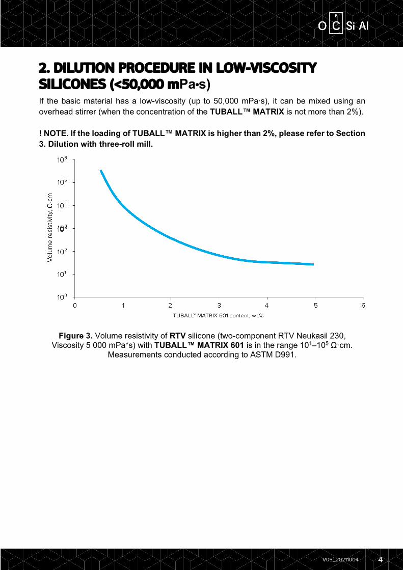
2. DILUTION PROCEDURE IN LOW-VISCOSITY SILICONES (<50,000 mPa·s) If the basic material has a low-viscosity (up to 50,000 mPa∙s), it can be mixed using an overhead stirrer (when the concentration of the TUBALL™ MATRIX is not more than 2%). ! NOTE. If the loading of TUBALL™ MATRIX is higher than 2%, please refer to Section 3. Dilution with three-roll mill.
Figure 3. Volume resistivity of RTV silicone (two-component RTV Neukasil 230, Viscosity 5 000 mPa*s) with TUBALL™ MATRIX 601 is in the range 101–105 Ω·cm.
Measurements conducted according to ASTM D991.

5 V05_202110041004
High-speed mixer For laboratory tests, a mechanical overhead stirrer with a mixing speed of up to 2,000 rpm (4.2 m/s) is used (such as the Heidolph RZR series or the IKA EUROSTAR series).
Dilution should conduct in a cylindrical mixing container with a flat base. An example of an overhead stirrer is shown in Figure 4. The recommended impeller blade shape for maximum effectiveness is shown in Figure 5. This is suitable for a silicone-TUBALL™ system with viscosity of not more than 250,000 mPa∙s when the concentration of the TUBALL™ MATRIX is not more than 2%.
! NOTE. 250,000 mPa∙s is the maximum viscosity that can be mixed on a high-speed mixer according to technical characteristics.
Figure 4. Example of an overhead stirrer
Figure 5. Recommended impeller blade shape
PRINCIPLES • The target dosage of TUBALL™ MATRIX refers to the loading in the whole final
formulation. • The temperature, duration and speed of mixing may need to be adjusted to obtain a
final mixture that is homogeneous. • Increasing the rotation speed is a more effective way to obtain better dispersion
quality than increasing the mixing time. • During the dilution process, check the impeller blade and the walls and base of the
container for adhered masses of TUBALL™ MATRIX.

6 V05_202110041004
Figure 6. The optimal relative position of the stirrer, container and mixed volume.
Peripheral speed, 4.2 m/s
DIAMETER, mm 50 100 150 200 250 300 350 400 450 500
SHAFT SPEED, rpm
1605 803 535 401 321 268 229 201 178 161
7 V05_202110041004
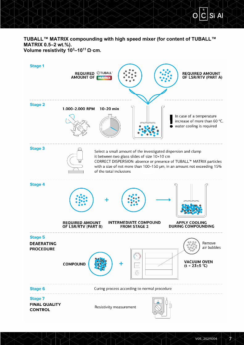
TUBALL™ MATRIX compounding with high speed mixer (for content of TUBALL™ MATRIX 0.5–2 wt.%). Volume resistivity 103–1011 Ω·cm.

8 V05_202110041004
3. DILUTION PROCEDURE IN HIGH-VISCOSITY SILICONES (>200,000 mPa·s)
Three-roll mill If the base material has higher viscosity (more than 200,000 mPa∙s, which is equal to more than 600,000 mPa·s with TUBALL™ MATRIX-silicone system), or a high concentration of TUBALL MATRIX is required (from 3 wt.% or more), a three-roll mill (TRM) is required to dilute the TUBALL™ MATRIX.
A three-roll mill is a machine composed of three horizontally positioned rollers rotating in opposite directions and at different speeds. The rollers create shear forces to mix, refine, disperse and homogenize viscous materials.
An example of a three-roll mill is shown in Figures 7 and 8. Figure 7. Example of a three-roll mill Figure 8. Schematic diagram of the general
configuration of a three-roll mill mechanism
Dispersion on three-roll mill The following are general recommendations on three-roll mill operating parameters:
Gap size between rolls
In terms of gap size regulation, there are two types of three-roll mill: • electronic with precise gap control; • mechanical with manual gap control. For electronic mills, a gradual decrease in the gap size should be used as the most efficient way to disperse TUBALL™. For mechanical mills, a constant gap size should be set up at the beginning and retained throughout all milling cycles. Examples of recommended parameters for both types of mill are provided in the table below.
Temperature control It is recommended to use internal water cooling to maintain the rollers at the proper temperature, for the best reproducibility of results. Set the temperature to a constant value between 15 °C and 30 °C.

9 V05_202110041004
Milling cycles The number of cycles required may vary depending on the type of three-roll mill and the carrier medium. Milling should be continued until the size of agglomerates decreases to a constant value or to a value suitable for your specific application. For an increased roller diameter, the number of milling cycles should be reduced. Excessive milling time increases the amount of damage to the nanotubes’ structure, resulting in reduced conductivity.
Hydraulic pressure For advanced three-roll mills with the ability to operate in force mode, OCSiAl recommends that the linear pressure between the feed roller and the center roller be set in the range of 3–5 N/cm, and that between the center and the delivery roller be set in the range of 10–15 N/cm and to process for 7–10 cycles.
The parameters outlined in the table below are based on tests carried out by OCSiAl in 2016–2018, but it is recommended that preliminary tests always be carried out to optimize results.
A single milling cycle includes: A. Loading material between the feed roller and the center roller; B. Passing material through the gaps between the rollers; C. Accumulating material on the knife edge after exiting the delivery roller.
The table below contains recommended parameters for three-roll mill operation. Introduction of TUBALL™ MATRIX into part A and part B (separately).
Table 1. Parameters of dispersion of TUBALL™ MATRIX into part A and part B on three-roll mills.
Model Gap
between rollers, μm
Number of cycles
Minimum batch, g
Maximum batch, g
Electronic mills (data for EXAKT 80E)
120/40 2 10 100
Mechanical mills (data for SOWER SW-S150)
40/20 2 100 —
Mechanical mills (data for SOWER SW-S150)
80/40 4 — 1,000
Mechanical mills (data for SOWER SW-S260)
80/40 4 1,000 —
Mechanical mills (data for SOWER SW-S260)
160/80 4 — 15,000
After introduction of TUBALL™ MATRIX into Part A and Part B, it may be mixed with a static mixer (injection molding) under normal conditions.

10 V05_202110041004
NOTE: Please note that the distribution of TUBALL™ MATRIX in the final compound depends on both stages – the initial compounding stage (introduction into Part A and B) and injection molding (compounding of Part A and B). Normally, injection molding does not require any specific conditions with TUBALL™ MATRIX presence, but a few options of initial compounding stage (introduction into Part A and B) may be tested in combination with normal injection molding regimes to determine an optimal result.
In laboratory-scale evaluation, Parts A and B can be mixed using of three-roll mills.
Table 2. Parameters of dispersion of compounded part A and part B on three-roll mills.
Model Gap between rollers, μm
Number of cycles
Minimum batch, g
Maximum batch, g
Electronic mills (data for EXAKT 80E)
45/15 5 10 100
Mechanical mills (data for SOWER SW-S150)
40/20 7 100 —
Mechanical mills (data for SOWER SW-S150)
80/40 7 — 1000
Mechanical mills (data for SOWER SW-S260)
80/40 7 1000 —
Mechanical mills (data for SOWER SW-S260)
160/80 7 — 15000

11 V05_202110041004
4. EXAMPLES OF CALCULATIONS AND COMPOUNDING High speed mixer for two-component low-viscosity silicone (< 50,000 mPa·s) compounds
Desired level of conductivity is 5∙102-1∙103 Ω·cm (2% TUBALL™ MATRIX 601) • Composition of final compound (1 kg):
49% of RTV component A — 490 g; 49% of RTV component B — 490 g; 2% of TUBALL™ MATRIX 601 — 20 g.
• Mix 20 g of TUBALL™ MATRIX 601 and 490 g of RTV component A. • Mix at 2.1–4.2 m/s for 10–20 minutes at room temperature until a good dispersion
quality is achieved. • Add 490 g of RTV component B. • Mix the system until it is homogeneous. • Initiate the curing process according to the standard procedure.
Three-roll mill for two-component high-viscosity (under 200,000 mPa·s) silicone compounds or high MATRIX dosage compounds (3 and more wt.% of TUBALL™ MATRIX) a) Volume resistivity 109–103 Ω·cm
Two-component silicone А:В (1:1) Desired level of resistivity below 102 Ω·cm (3–5% TUBALL™ MATRIX 601, depending on the viscosity of silicone)
• Composition of final compound (1 kg): 47.5% of component A — 475 g; 47.5% of component B — 475 g; 5% of TUBALL™ MATRIX 601 — 50 g.
• Mix 25 g of TUBALL™ MATRIX 601 and 475 g of component A using three-roll mill (dispersion 1).
• Mix 25 g of TUBALL™ MATRIX 601 and 475 g of component В using three-roll mill (dispersion 2).
• Mix dispersion 1 and dispersion 2 using three-roll mill. b) Two-component silicone A:B (9:1). Desired level of resistivity below 102 Ω·cm
(5% TUBALL™ MATRIX 601). • Composition of final compound (1 kg):
85.5% of RTV component A — 855 g; 9.5% of RTV component B — 95 g; 5% of TUBALL™ MATRIX 601 — 50 g.
• Mix 50 g of TUBALL™ MATRIX 601 and 855 g of RTV component A using three-roll mill (dispersion 1).
• Mix dispersion 1 and component B using three-roll mill.
12 V05_202110041004
The number of milling cycles and the spacing between shafts can changed and should be optimized for the specific materials. Examples are given on the basis of OCSiAl experiments. The exact concentration depends on the viscosity of the basic material, parameters of equipment, etc. For an exact regime for three-roll mill, refer to Tables 1 and 2 above.
5. DISPERSION QUALITY CONTROL
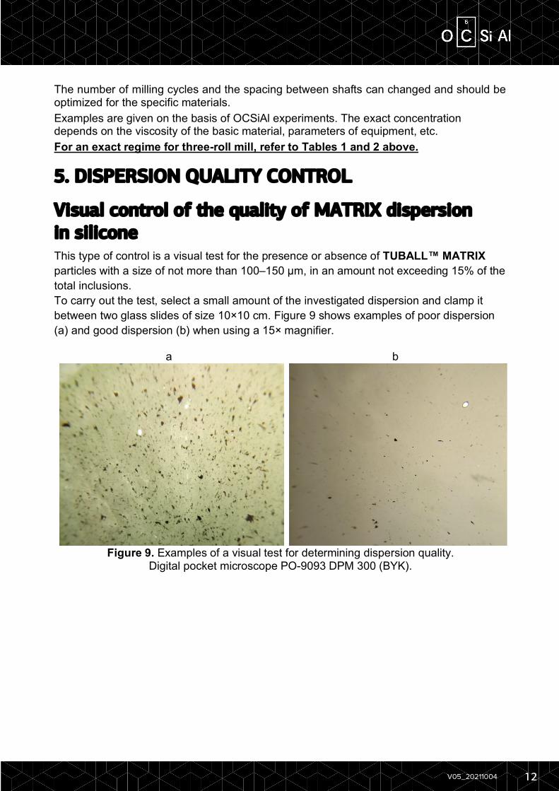
Visual control of the quality of MATRIX dispersion in silicone This type of control is a visual test for the presence or absence of TUBALL™ MATRIX particles with a size of not more than 100–150 μm, in an amount not exceeding 15% of the total inclusions. To carry out the test, select a small amount of the investigated dispersion and clamp it between two glass slides of size 10×10 cm. Figure 9 shows examples of poor dispersion (a) and good dispersion (b) when using a 15× magnifier.
a b
Figure 9. Examples of a visual test for determining dispersion quality.
Digital pocket microscope PO-9093 DPM 300 (BYK).

13 V05_202110041004
Measurement of resistivity For measurements of resistivity of uncured samples based on RTV or LSR, a hollow cylindrical cell with dimensions limited by electrodes with the same shape can be used. The resistance is measured with a multimeter connected to the electrodes. This method and equipment can be used when the target specific resistance value in the material is 107 Ω·cm or lower.
STANDARD Measurement is conducted according to the OCSiAl test method based on ISO 3915 “Plastics — Measurement of resistivity of conductive plastics” and adapted for conductivity measurement of paste-form substances.
EQUIPMENT • Current/voltage source 0-50 V, 0-3 A; • Ammeter from 10 µA; • Voltmeter with accuracy of 1 mV; • 4-probe electrode cell (Figure 10).
PROCEDURE Loading of a sample After inserting one of the current electrodes, load the sample holding the cell in a vertical position. After filling sample to the top, insert a second electrode and put the cell horizontally on a table. Insert the electrodes for voltage measurement. The cell is ready for measurement.
Connection of devices Connect all devices according to the diagram shown below. Pay attention to connect the ammeter first to the current source and then to the cell.
Figure 11. Diagram of electrical circuit
Figure 10. 4-probe cell

14 V05_202110041004
Taking measurements After connecting all devices, switch on the ammeter, voltmeter and current/voltage source. Gradually applying a voltage of up to 50 V, set the corresponding range for current and voltage measurement.
Figure 12. An example of a measurement set-up.
Calculations
Resistance R in Ohm units (Ω), should be calculated by the following formula
𝑅 = ∆%&
(1)
15 V05_202110041004
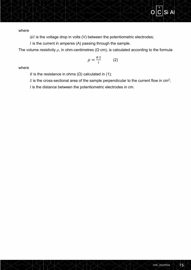
where ∆𝑈 is the voltage drop in volts (V) between the potentiometric electrodes; 𝐼 is the current in amperes (A) passing through the sample. The volume resistivity 𝜌, in ohm-centimetres (Ω·cm), is calculated according to the formula
𝜌 = *∙,-
(2)
where 𝑅 is the resistance in ohms (Ω) calculated in (1); 𝑆 is the cross-sectional area of the sample perpendicular to the current flow in cm2; 𝑙 is the distance between the potentiometric electrodes in cm.

16 V05_202110041004
6. TROUBLESHOOTING Shelf life of compound The shelf life of the final compound in the uncured state must be determined experimentally for each particular compound. According to OCSiAl internal tests, liquid silicone rubbers compounded with TUBALL™ MATRIX 601, 602 and 613 beta has stable electrical properties for up to 6-10 months.
Impact on curing parameters TUBALL™ MATRIX 601, 602 and 613 beta are compatible with the platinum curing system. In cases where a high loading of TUBALL™ MATRIX (5 wt.% and more) is required to achieve low electrical resistivity compounds, some impact on the curing system may occur. In this case, adjustment of the curing system is required.
Post curing Electrical conductivity is typically increased by the post-curing process. For example, a volume resistivity of 108 Ω·cm after curing will improve further down to 106 Ω·cm after post curing for 4 hours at 200 °C. The exact impact depends on the curing agents and the molding process.
Molding process Electrical conductivity may be affected by the molding process due to differences in the shear forces. All the data provided in technical documents is based on a compression molding process. • Compression molding — no impact on electrical conductivity. • Injection molding — resistivity is higher than with compression-molded parts. The exact impact on electrical resistivity of the molding process should be determined experimentally.
Impact on color An example of compounding of colored samples by a three-roll mill follows. Two-component silicone А:В (1:1) Desired level of resistivity 105–107 Ω·cm (1–1,5% TUBALL™ MATRIX 601, depending on the viscosity of the silicone) • Composition of final compound (1 kg):
46% of component A — 460 g; 46% of component B — 460 g; 1% of TUBALL™ MATRIX 601 — 10 g; 2% of white pigment (paste) — 20 g; 5–10% of red (or other color) pigment (paste) — 50–100 g.
• Mix 5 g of TUBALL™ MATRIX 601, 10 g white paste, 25 g (if 5%) red paste and 460 g of component A using 4 cycles (dispersion 1).
• Mix 5 g of TUBALL™ MATRIX 601, 10 g white paste, 25 g (if 5%) red paste and 460 g of component B using 4 cycles (dispersion 2).
17 V05_202110041004
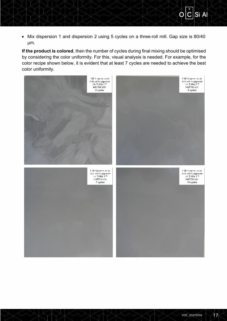
• Mix dispersion 1 and dispersion 2 using 5 cycles on a three-roll mill. Gap size is 80/40 μm.
If the product is colored, then the number of cycles during final mixing should be optimised by considering the color uniformity. For this, visual analysis is needed. For example, for the color recipe shown below, it is evident that at least 7 cycles are needed to achieve the best color uniformity.