principles of radar systems, 1-1 basic principles of … are two basic types of crt displays: the...
TRANSCRIPT
© Festo Didactic 38542-00 7
When you have completed this exercise, you will be familiar with the basic principles of pulsed radar. You will also be familiar with the Radar Training System, including the A-scope display, and with safety measures applicable to all radar systems.
The Discussion of this exercise covers the following points:
A pulsed radar system
The Radar Training System
Safety
A pulsed radar system
In a pulsed radar system, short bursts of radio frequency (RF) energy are generated for transmission. This is usually accomplished by first generating a train of narrow, rectangular-shape pulses and using these to amplitude-modulate a sinewave RF carrier. The pulsed RF signal is transmitted by the antenna. If the signal strikes a target, a portion of the signal will be reflected back to the radar as an echo. The antenna captures the echo pulses which are sent to the receiver. The received pulses are then demodulated and converted to a video signal for display.
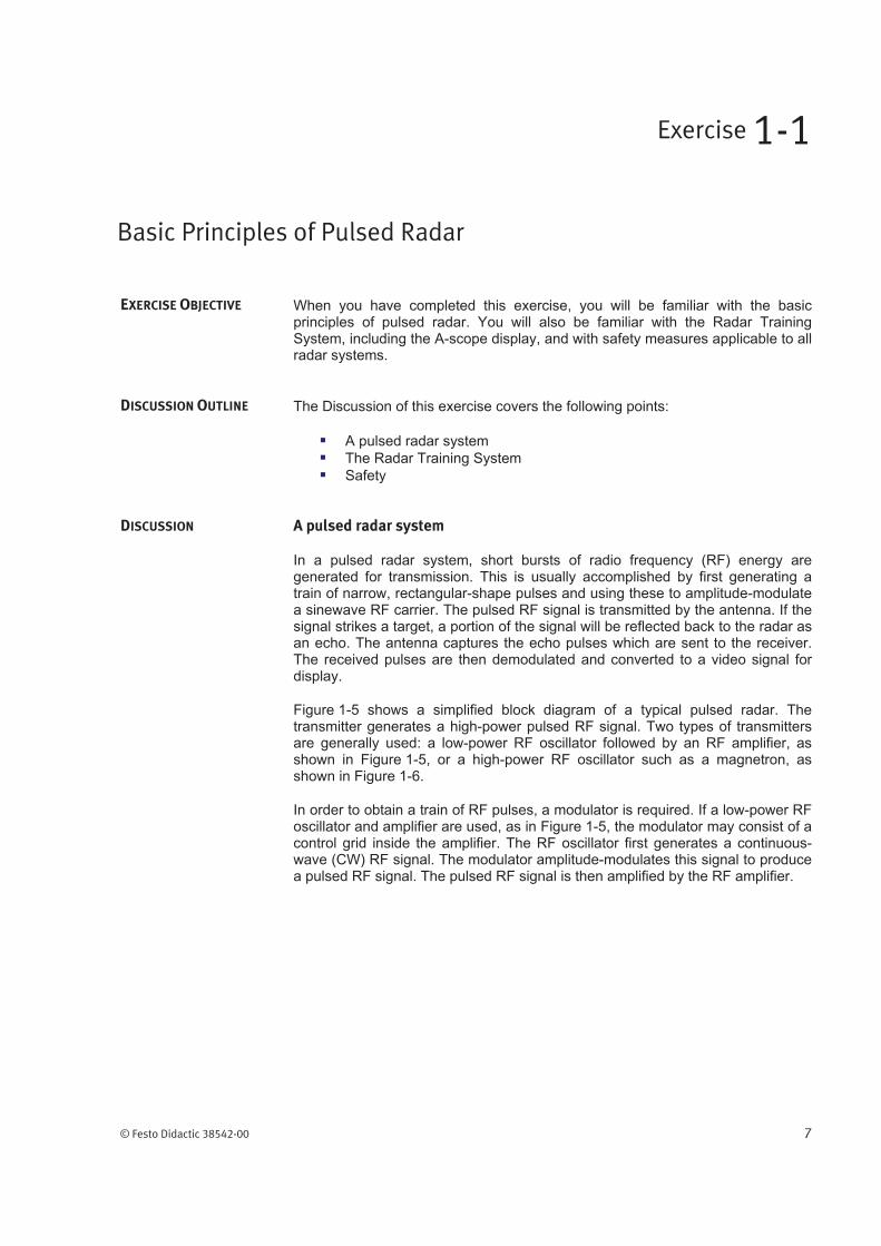
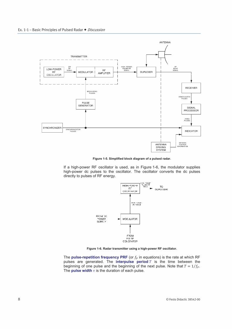
Figure 1-5 shows a simplified block diagram of a typical pulsed radar. The transmitter generates a high-power pulsed RF signal. Two types of transmitters are generally used: a low-power RF oscillator followed by an RF amplifier, as shown in Figure 1-5, or a high-power RF oscillator such as a magnetron, as shown in Figure 1-6.
In order to obtain a train of RF pulses, a modulator is required. If a low-power RF oscillator and amplifier are used, as in Figure 1-5, the modulator may consist of a control grid inside the amplifier. The RF oscillator first generates a continuous-wave (CW) RF signal. The modulator amplitude-modulates this signal to produce a pulsed RF signal. The pulsed RF signal is then amplified by the RF amplifier.
Basic Principles of Pulsed Radar
Exercise 1-1
EXERCISE OBJECTIVE
DISCUSSION OUTLINE
DISCUSSION
Ex. 1-1 – Basic Principles of Pulsed Radar Discussion
8 © Festo Didactic 38542-00
Figure 1-5. Simplified block diagram of a pulsed radar.
If a high-power RF oscillator is used, as in Figure 1-6, the modulator supplies high-power dc pulses to the oscillator. The oscillator converts the dc pulses directly to pulses of RF energy.
Figure 1-6. Radar transmitter using a high-power RF oscillator.
The pulse-repetition frequency PRF (or in equations) is the rate at which RF pulses are generated. The interpulse period is the time between the
beginning of one pulse and the beginning of the next pulse. Note that . The pulse width is the duration of each pulse.
Ex. 1-1 – Basic Principles of Pulsed Radar Discussion
© Festo Didactic 38542-00 9
If the radar transmitter and receiver share a common antenna, as in Figure 1-5, a duplexer is required. The role of the duplexer is to automatically route the transmitted signal from the transmitter to the antenna, and the received signal from the antenna to the receiver, but prevent the transmitted signal from passing directly to the receiver. This is necessary to prevent damage to the sensitive input stages of the receiver.
Generally speaking, any device which allows the transmitter and the receiver to share a common antenna is called a duplexer. High-power radar systems often use duplexers containing power-sensitive gas discharge tubes to direct the transmitted or received signal. In low-power systems, a solid-state ferrite circulator may be used as a duplexer. A circulator is a multi-terminal coupler in which microwave energy is transmitted only from one terminal to the next.
The antenna in a radar system is the transition device between waveguides or transmission lines and free space. The antenna is usually designed to concentrate the transmitted signal into a narrow beam. By orienting the antenna, this beam can be pointed in various directions, thus allowing the radar to determine the direction of the target. Although most pulsed radar systems use a common antenna for both transmission and reception, some systems use two separate antennas.
The antenna driving system is used to orient the antenna. The antenna may be made to rotate, to scan over a limited angle or area, or to track a moving target, depending on the application.
The echo received by the antenna is directed by the duplexer to the receiver. The role of the receiver is to demodulate the echo signal and produce a signal which can be processed and sent to the display.
Many pulsed radar systems include some sort of signal processor. The signal processor may provide such functions as the reduction of unwanted echoes, the reduction of interference and noise, and various types of automatic detection.
The purpose of the indicator is to convey target information to the radar operator. The type of indicator used depends on the particular radar application. In pulsed radars, the indicator usually consists of some type of cathode-ray tube (CRT) display. Other circuitry, such as circuitry to allow tracking moving targets for example, may also be part of the indicator.
There are two basic types of CRT displays: the deflection-modulated CRT display and the intensity-modulated CRT display. In a deflection-modulated display, the presence of a target is indicated by the deflection of the electron beam. In an intensity-modulated display, a target is indicated by intensifying the electron beam in order to cause a luminous spot to appear in the CRT. The deflection of the beam, and the luminous spot, are called blips.
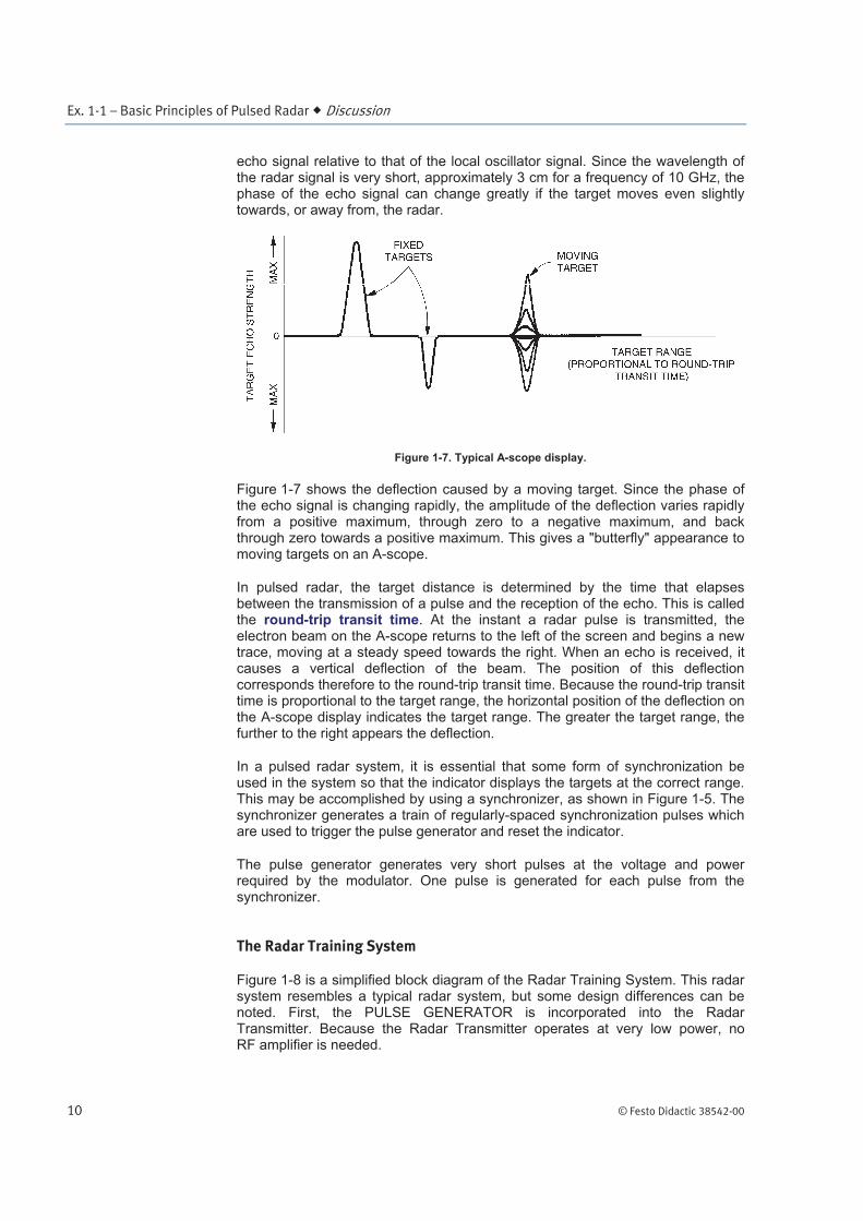
One very common deflection-modulated display is the A-scope. In the A-scope display, the vertical deflection is proportional to the target echo strength, and the horizontal coordinate of the deflection is proportional to the target range.
Figure 1-7 shows a typical A-scope display. Three deflections are shown. The two deflections to the left correspond to two fixed targets. The stronger the echo from a particular target, the greater the deflection from zero on the display. The actual amplitude of the deflection, and its sign, also depend on the phase of the
Ex. 1-1 – Basic Principles of Pulsed Radar Discussion
10 © Festo Didactic 38542-00
echo signal relative to that of the local oscillator signal. Since the wavelength of the radar signal is very short, approximately 3 cm for a frequency of 10 GHz, the phase of the echo signal can change greatly if the target moves even slightly towards, or away from, the radar.
Figure 1-7. Typical A-scope display.
Figure 1-7 shows the deflection caused by a moving target. Since the phase of the echo signal is changing rapidly, the amplitude of the deflection varies rapidly from a positive maximum, through zero to a negative maximum, and back through zero towards a positive maximum. This gives a "butterfly" appearance to moving targets on an A-scope.
In pulsed radar, the target distance is determined by the time that elapses between the transmission of a pulse and the reception of the echo. This is called the round-trip transit time. At the instant a radar pulse is transmitted, the electron beam on the A-scope returns to the left of the screen and begins a new trace, moving at a steady speed towards the right. When an echo is received, it causes a vertical deflection of the beam. The position of this deflection corresponds therefore to the round-trip transit time. Because the round-trip transit time is proportional to the target range, the horizontal position of the deflection on the A-scope display indicates the target range. The greater the target range, the further to the right appears the deflection.
In a pulsed radar system, it is essential that some form of synchronization be used in the system so that the indicator displays the targets at the correct range. This may be accomplished by using a synchronizer, as shown in Figure 1-5. The synchronizer generates a train of regularly-spaced synchronization pulses which are used to trigger the pulse generator and reset the indicator.
The pulse generator generates very short pulses at the voltage and power required by the modulator. One pulse is generated for each pulse from the synchronizer.
The Radar Training System
Figure 1-8 is a simplified block diagram of the Radar Training System. This radar system resembles a typical radar system, but some design differences can be noted. First, the PULSE GENERATOR is incorporated into the Radar Transmitter. Because the Radar Transmitter operates at very low power, no RF amplifier is needed.
Ex. 1-1 – Basic Principles of Pulsed Radar Discussion
© Festo Didactic 38542-00 11
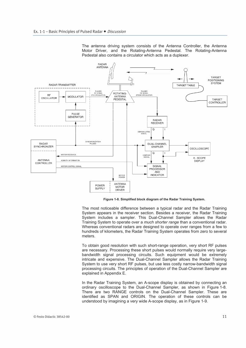
The antenna driving system consists of the Antenna Controller, the Antenna Motor Driver, and the Rotating-Antenna Pedestal. The Rotating-Antenna Pedestal also contains a circulator which acts as a duplexer.
Figure 1-8. Simplified block diagram of the Radar Training System.
The most noticeable difference between a typical radar and the Radar Training System appears in the receiver section. Besides a receiver, the Radar Training System includes a sampler. This Dual-Channel Sampler allows the Radar Training System to operate over a much shorter range than a conventional radar. Whereas conventional radars are designed to operate over ranges from a few to hundreds of kilometers, the Radar Training System operates from zero to several meters.
To obtain good resolution with such short-range operation, very short RF pulses are necessary. Processing these short pulses would normally require very large-bandwidth signal processing circuits. Such equipment would be extremely intricate and expensive. The Dual-Channel Sampler allows the Radar Training System to use very short RF pulses, but use less costly narrow-bandwidth signal processing circuits. The principles of operation of the Dual-Channel Sampler are explained in Appendix E.
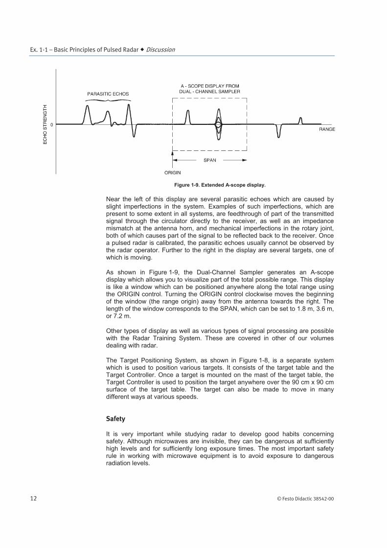
In the Radar Training System, an A-scope display is obtained by connecting an ordinary oscilloscope to the Dual-Channel Sampler, as shown in Figure 1-8. There are two RANGE controls on the Dual-Channel Sampler. These are identified as SPAN and ORIGIN. The operation of these controls can be understood by imagining a very wide A-scope display, as in Figure 1-9.
Ex. 1-1 – Basic Principles of Pulsed Radar Discussion
12 © Festo Didactic 38542-00
Figure 1-9. Extended A-scope display.
Near the left of this display are several parasitic echoes which are caused by slight imperfections in the system. Examples of such imperfections, which are present to some extent in all systems, are feedthrough of part of the transmitted signal through the circulator directly to the receiver, as well as an impedance mismatch at the antenna horn, and mechanical imperfections in the rotary joint, both of which causes part of the signal to be reflected back to the receiver. Once a pulsed radar is calibrated, the parasitic echoes usually cannot be observed by the radar operator. Further to the right in the display are several targets, one of which is moving.
As shown in Figure 1-9, the Dual-Channel Sampler generates an A-scope display which allows you to visualize part of the total possible range. This display is like a window which can be positioned anywhere along the total range using the ORIGIN control. Turning the ORIGIN control clockwise moves the beginning of the window (the range origin) away from the antenna towards the right. The length of the window corresponds to the SPAN, which can be set to 1.8 m, 3.6 m, or 7.2 m.
Other types of display as well as various types of signal processing are possible with the Radar Training System. These are covered in other of our volumes dealing with radar.
The Target Positioning System, as shown in Figure 1-8, is a separate system which is used to position various targets. It consists of the target table and the Target Controller. Once a target is mounted on the mast of the target table, the Target Controller is used to position the target anywhere over the 90 cm x 90 cm surface of the target table. The target can also be made to move in many different ways at various speeds.
Safety
It is very important while studying radar to develop good habits concerning safety. Although microwaves are invisible, they can be dangerous at sufficiently high levels and for sufficiently long exposure times. The most important safety rule in working with microwave equipment is to avoid exposure to dangerous radiation levels.
Ex. 1-1 – Basic Principles of Pulsed Radar Discussion
© Festo Didactic 38542-00 13
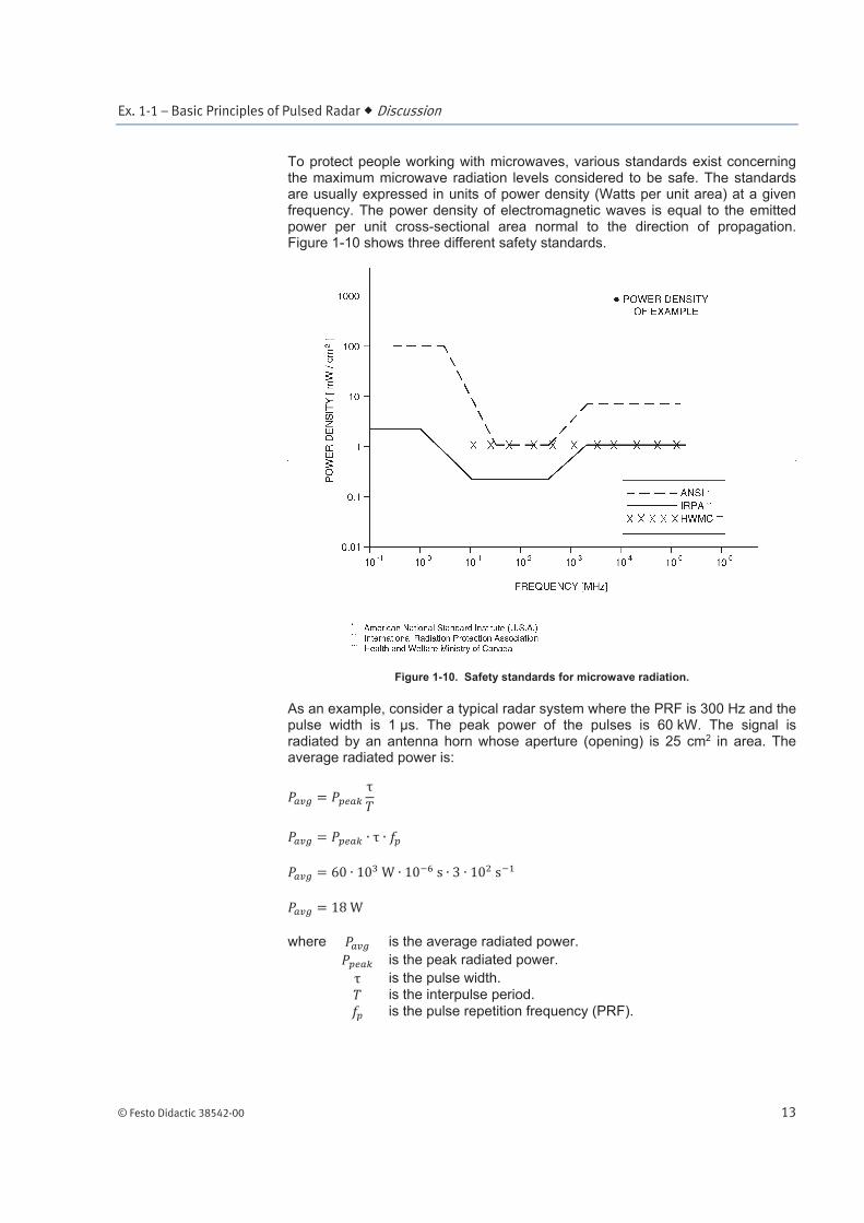
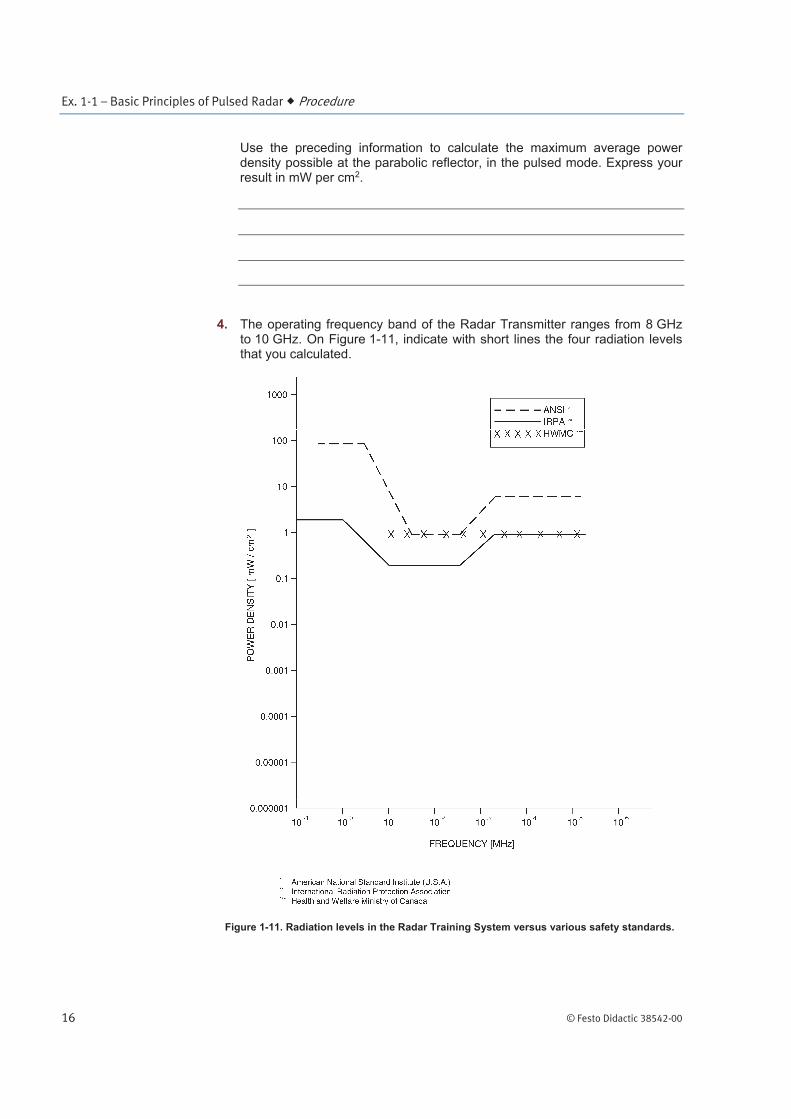
To protect people working with microwaves, various standards exist concerning the maximum microwave radiation levels considered to be safe. The standards are usually expressed in units of power density (Watts per unit area) at a given frequency. The power density of electromagnetic waves is equal to the emitted power per unit cross-sectional area normal to the direction of propagation. Figure 1-10 shows three different safety standards.
Figure 1-10. Safety standards for microwave radiation.
As an example, consider a typical radar system where the PRF is 300 Hz and the pulse width is 1 s. The peak power of the pulses is 60 kW. The signal is radiated by an antenna horn whose aperture (opening) is 25 cm2 in area. The average radiated power is:
where is the average radiated power.
is the peak radiated power.
is the pulse width. is the interpulse period.
is the pulse repetition frequency (PRF).
Ex. 1-1 – Basic Principles of Pulsed Radar Procedure Outline
14 © Festo Didactic 38542-00
The power density of a microwave beam is equal to the power of the average radiated power divided by the area of the beam. The power density at the aperture of the horn in the example is therefore:
If the carrier frequency in the example is 10 GHz, this level of radiation is considered hazardous according to all of the standards in Figure 1-10, as indicated by the point marked POWER DENSITY OF EXAMPLE.
Although power levels in the system are too low to be dangerous (these are calculated in the procedure of this exercise), you should begin now to practice several elementary safety rules which apply to full-scale radar systems:
never look directly into a source of microwaves, such as a waveguide or horn.
obey all warnings such as "RADIATION HAZARD".
turn off the RF power before placing yourself in front of the antenna. Most radars have a means of doing this.
a In some exercises in the Radar courseware series, you will be required to stand in front of the antenna and adjust the target while the system is transmitting. Although this is not dangerous with the Radar Training System, keep in mind that the radiation from a full-scale, high-power radar is dangerous. In order to develop good safety habits, you should, whenever possible, set the RF POWER switch on the Radar Transmitter to the STANDBY position before placing yourself in front of the antenna.
The Procedure is divided into the following sections:
Radiation levels in the Radar Training System
Setting up a basic pulse radar
Observation of various blips on an A-scope display
Radiation levels in the Radar Training System
In this section, you will calculate the various radiation levels that can be found in the Radar Training System. You will compare these radiation levels to the maximum levels allowed by various safety standards.
1. The Radar Transmitter provides approximately 2 mW of RF power when operating in the CW or FM-CW (frequency-modulated CW) modes.
PROCEDURE OUTLINE
PROCEDURE
Ex. 1-1 – Basic Principles of Pulsed Radar Procedure
© Festo Didactic 38542-00 15
At the aperture of the horn, the area of the radiated-energy beam is equal to the area of the aperture. On the Radar Antenna, this corresponds to approximately 25 cm2.
Use the preceding information to calculate the power density at the aperture of the horn, in the CW mode. Express your result in mW per cm2.
2. The radiated-energy beam coming from the horn spreads as it travels towards the parabolic reflector of the antenna. When it strikes the parabolic reflector, its area is approximately equal to the aperture of the parabolic reflector, that is 490 cm2.
Use the preceding information to calculate the power density at the parabolic reflector, in the CW mode. Express your result in mW per cm2.
3. The Radar Transmitter provides pulses of RF power when operating in the pulsed mode. The width of these pulses can vary between 1 and 5 ns, and their peak power is approximately equal to 2 mW.
The following five PRFs can be selected with the Radar Training System: 12, 18, 144, 216 and 288 Hz. Due to the design of the Radar Training System, the actual PRF is equal to 1024 times the selected PRF. This is explained in Appendix E of this manual.
a In this manual, the selected PRF should be used in all calculations, unless you are specifically instructed to use the actual PRF.
Use the preceding information to calculate the maximum average power density possible at the aperture of the horn, in the pulsed mode. Use the actual PRFs, and express your result in mW per cm2.
Ex. 1-1 – Basic Principles of Pulsed Radar Procedure
16 © Festo Didactic 38542-00
Use the preceding information to calculate the maximum average power density possible at the parabolic reflector, in the pulsed mode. Express your result in mW per cm2.
4. The operating frequency band of the Radar Transmitter ranges from 8 GHz to 10 GHz. On Figure 1-11, indicate with short lines the four radiation levels that you calculated.
Figure 1-11. Radiation levels in the Radar Training System versus various safety standards.
Ex. 1-1 – Basic Principles of Pulsed Radar Procedure
© Festo Didactic 38542-00 17
What do you conclude about the radiation levels that can be found in the Radar Training System?
Setting up a basic pulse radar
In this section, you will set up a basic pulsed radar. The block diagram of the system you will use is shown in Figure 1-13. This will allow you to become familiar with the Radar Training System.
5. The main elements of the Radar Training System, that is the antenna and its pedestal, the target table and the training modules, must be set up properly before beginning this exercise. Refer to Appendix B of this manual for setting up the Radar Training System, if this is not done yet.
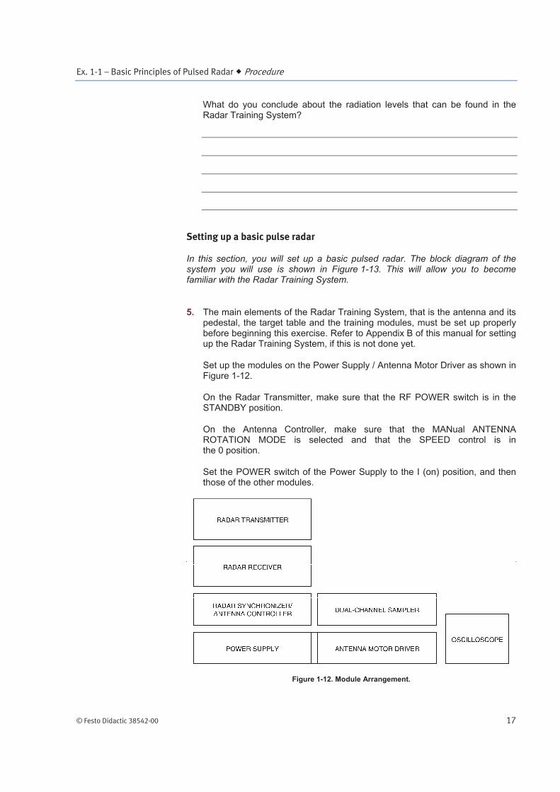
Set up the modules on the Power Supply / Antenna Motor Driver as shown in Figure 1-12.
On the Radar Transmitter, make sure that the RF POWER switch is in the STANDBY position.
On the Antenna Controller, make sure that the MANual ANTENNA ROTATION MODE is selected and that the SPEED control is in the 0 position.
Set the POWER switch of the Power Supply to the I (on) position, and then those of the other modules.
Figure 1-12. Module Arrangement.
Ex. 1-1 – Basic Principles of Pulsed Radar Procedure
18 © Festo Didactic 38542-00
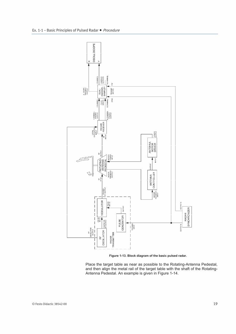
6. Figure 1-13 shows the block diagram of the basic pulsed radar that can be obtained using the Radar Training System. Connect the modules according to this block diagram.
a Unless otherwise specified, you should respect the following cable lengths for connecting the RF section of the Radar Training System (refer to the List of Equipment Required near the beginning of this manual for exact cable lengths):
Use long SMA cables (approximately 2 m) to connect the Rotating-Antenna Pedestal to the Radar Transmitter and Radar Receiver.
Use a short SMA cable (approximately 40 cm) to connect the RF OSCILLATOR OUTPUT of the Radar Transmitter to the LOCAL OSCILLATOR INPUT of the Radar Receiver.
Use short SMA cables (approximately 40 cm) with limiters to connect the I- and Q-CHANNEL PULSED OUTPUTs of the Radar Receiver to the I- and Q-CHANNEL PULSE INPUTS of the Dual-Channel Sampler.
Use semi-rigid SMA cables (those having a U shape) to make the connections required on the Radar Transmitter.
7. On the Radar Transmitter, depress the CALibrated FREQUENCY push button of the RF OSCILLATOR. This sets the frequency of the RF OSCILLATOR signal to 9.4 GHz, as indicated by the FREQUENCY display of the Radar Transmitter.
On the PULSE GENERATOR, select the 1-ns PULSE WIDTH.
On the Radar Synchronizer, make sure that the SINGLE PRF MODE and
the 216 Hz PRF are selected.
8. Connect the cable of the target table to the multi-pin connector located on the rear panel of the Target Controller. Make sure that the surface of the target table is free of any objects and then set the POWER switch of the Target Positioning System to the I (on) position.
a When the Target Positioning System is powered up, it automatically performs a self-calibration routine, then the POSITION MODE is automatically selected on the Target Controller. When this mode is selected, the movable carriage moves to the centre of the target table.
Ex. 1-1 – Basic Principles of Pulsed Radar Procedure
© Festo Didactic 38542-00 19
Figure 1-13. Block diagram of the basic pulsed radar.
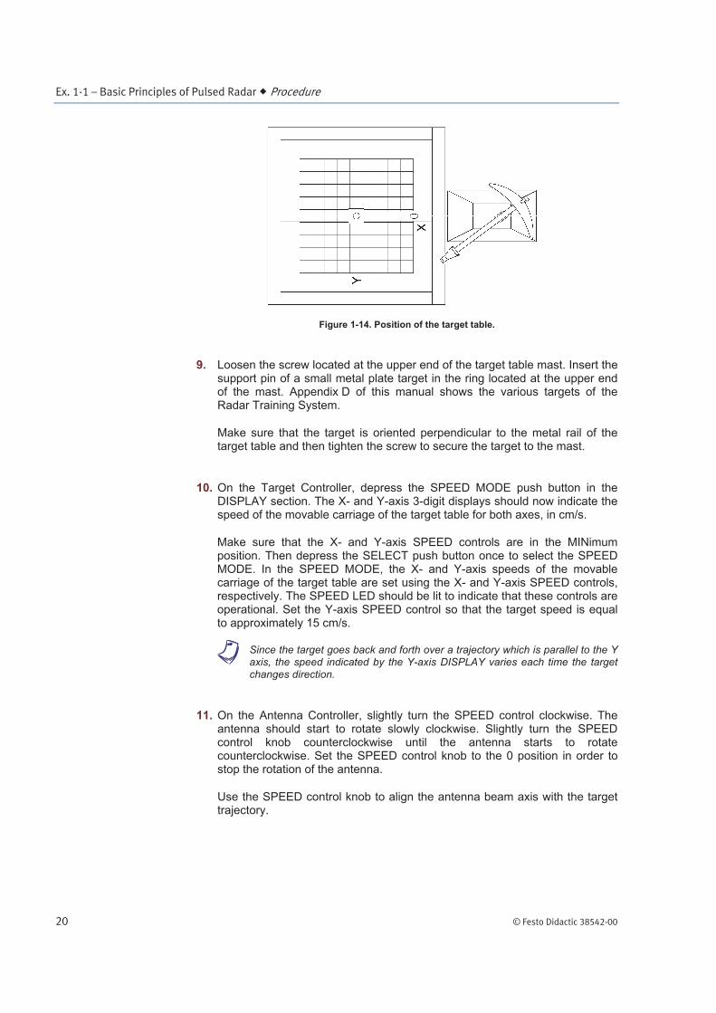
Place the target table as near as possible to the Rotating-Antenna Pedestal, and then align the metal rail of the target table with the shaft of the Rotating-Antenna Pedestal. An example is given in Figure 1-14.
Ex. 1-1 – Basic Principles of Pulsed Radar Procedure
20 © Festo Didactic 38542-00
Figure 1-14. Position of the target table.
9. Loosen the screw located at the upper end of the target table mast. Insert the support pin of a small metal plate target in the ring located at the upper end of the mast. Appendix D of this manual shows the various targets of the Radar Training System.
Make sure that the target is oriented perpendicular to the metal rail of the target table and then tighten the screw to secure the target to the mast.
10. On the Target Controller, depress the SPEED MODE push button in the DISPLAY section. The X- and Y-axis 3-digit displays should now indicate the speed of the movable carriage of the target table for both axes, in cm/s.
Make sure that the X- and Y-axis SPEED controls are in the MINimum position. Then depress the SELECT push button once to select the SPEED MODE. In the SPEED MODE, the X- and Y-axis speeds of the movable carriage of the target table are set using the X- and Y-axis SPEED controls, respectively. The SPEED LED should be lit to indicate that these controls are operational. Set the Y-axis SPEED control so that the target speed is equal to approximately 15 cm/s.
a Since the target goes back and forth over a trajectory which is parallel to the Y axis, the speed indicated by the Y-axis DISPLAY varies each time the target changes direction.
11. On the Antenna Controller, slightly turn the SPEED control clockwise. The antenna should start to rotate slowly clockwise. Slightly turn the SPEED control knob counterclockwise until the antenna starts to rotate counterclockwise. Set the SPEED control knob to the 0 position in order to stop the rotation of the antenna.
Use the SPEED control knob to align the antenna beam axis with the target trajectory.
Ex. 1-1 – Basic Principles of Pulsed Radar Procedure
© Festo Didactic 38542-00 21
12. Adjust the oscilloscope as follows:
Time Base ..................................................... X-Y Channel X ...................................................... 0.2 V/DIV (DC coupled) Channel Y ...................................................... 0.5 V/DIV (Set to GND)
Set the X- and Y-position controls of the oscilloscope so that the trace is centred on the screen.
On the Dual-Channel Sampler, depress the 1.8-m RANGE SPAN push button. This selects the range span covered by the A-scope display. Turn the ORIGIN control fully clockwise. Make sure that the GAIN controls are in the CALibrated position. This ensures that the gains of the I and Q channels of the Dual-Channel Sampler are properly set.
13. On the Radar Transmitter, depress the RF POWER push button. The RF POWER ON LED should start to flash on and off. This indicates that the RF OSCILLATOR signal reaches the DIRECTIONAL COUPLER and the MODULATOR. Part of this signal then reaches the antenna, where it is radiated.
a Since the radiation levels of the Radar Training System are very low, there is no danger to anyone standing near or in front of the antenna. Remember however, that with a full-scale radar, you must always make sure that no one could be exposed to dangerous radiation levels before turning on the RF power.
Set the Y-channel input coupling switch of the oscilloscope to the DC position. If an offset voltage is present at the I-CHANNEL SAMPLED OUTPUT of the Dual-Channel Sampler, the trace on the oscilloscope screen will shift up or down. If this happens, adjust the I-CHANNEL DC OFFSET control of the Dual-Channel Sampler so that the trace is centred on the oscilloscope screen.
Observation of various blips on an A-scope display
In this section, you will observe various blips from targets and the parasitic blips that often affect a pulsed radar on the A-scope display. You will then observe the blips from various metallic objects around the laboratory.
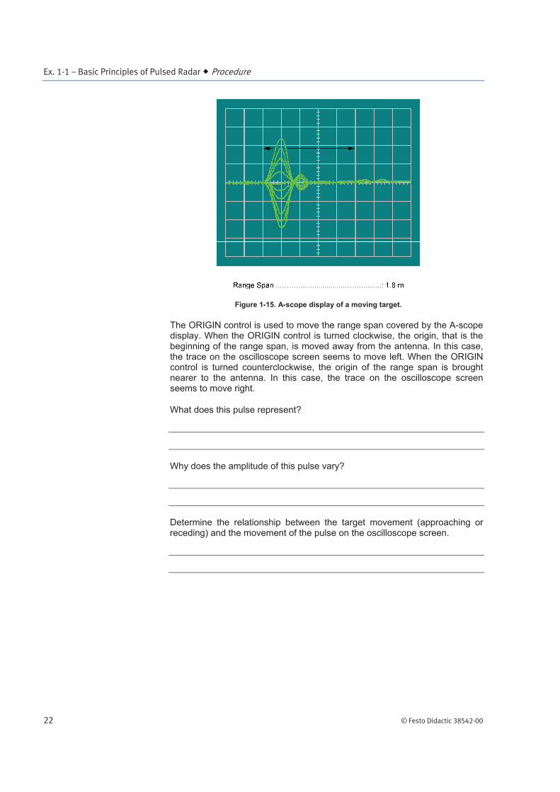
14. On the Dual-Channel Sampler, slowly turn the ORIGIN control counter- clockwise until a variable amplitude pulse (butterfly pattern) appears on the oscilloscope screen. The display on the oscilloscope should resemble Figure 1-15. The arrows indicate the displacement of the pulse on the oscilloscope screen.
Ex. 1-1 – Basic Principles of Pulsed Radar Procedure
22 © Festo Didactic 38542-00
Figure 1-15. A-scope display of a moving target.
The ORIGIN control is used to move the range span covered by the A-scope display. When the ORIGIN control is turned clockwise, the origin, that is the beginning of the range span, is moved away from the antenna. In this case, the trace on the oscilloscope screen seems to move left. When the ORIGIN control is turned counterclockwise, the origin of the range span is brought nearer to the antenna. In this case, the trace on the oscilloscope screen seems to move right.
What does this pulse represent?
Why does the amplitude of this pulse vary?
Determine the relationship between the target movement (approaching or receding) and the movement of the pulse on the oscilloscope screen.
Ex. 1-1 – Basic Principles of Pulsed Radar Procedure
© Festo Didactic 38542-00 23
15. On the Antenna Controller, use the SPEED control to rotate the antenna so that its beam axis is not aligned with the target trajectory. A rotation of about 10 to 20 degrees should be sufficient.
What happens to the pulse from the moving target? Explain.
On the Antenna Controller, use the SPEED control in order to align the antenna beam axis with the target trajectory. The optimum alignment is obtained when the pulse amplitude range is maximal on the oscilloscope screen.
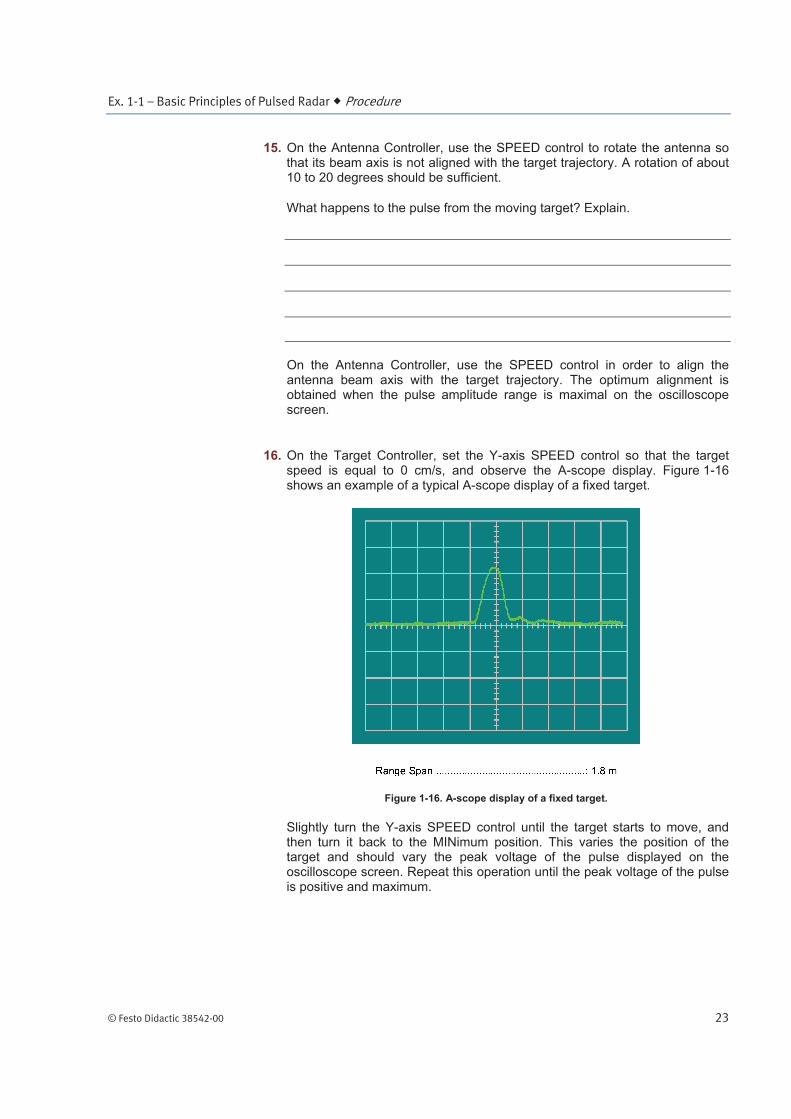
16. On the Target Controller, set the Y-axis SPEED control so that the target speed is equal to 0 cm/s, and observe the A-scope display. Figure 1-16 shows an example of a typical A-scope display of a fixed target.
Figure 1-16. A-scope display of a fixed target.
Slightly turn the Y-axis SPEED control until the target starts to move, and then turn it back to the MINimum position. This varies the position of the target and should vary the peak voltage of the pulse displayed on the oscilloscope screen. Repeat this operation until the peak voltage of the pulse is positive and maximum.
Ex. 1-1 – Basic Principles of Pulsed Radar Procedure
24 © Festo Didactic 38542-00
Compare the A-scope displays of a moving target (Figure 1-15) and of a fixed target (Figure 1-16).
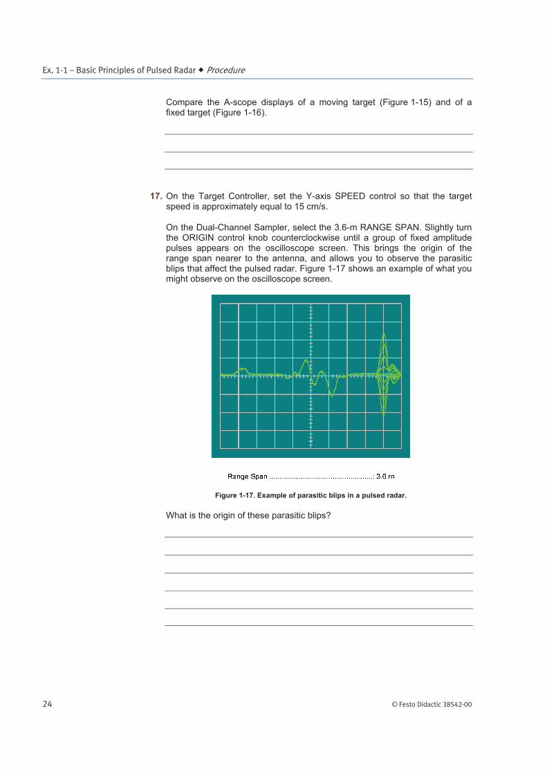
17. On the Target Controller, set the Y-axis SPEED control so that the target speed is approximately equal to 15 cm/s.
On the Dual-Channel Sampler, select the 3.6-m RANGE SPAN. Slightly turn the ORIGIN control knob counterclockwise until a group of fixed amplitude pulses appears on the oscilloscope screen. This brings the origin of the range span nearer to the antenna, and allows you to observe the parasitic blips that affect the pulsed radar. Figure 1-17 shows an example of what you might observe on the oscilloscope screen.
Figure 1-17. Example of parasitic blips in a pulsed radar.
What is the origin of these parasitic blips?
Ex. 1-1 – Basic Principles of Pulsed Radar Conclusion
© Festo Didactic 38542-00 25
18. On the Antenna Controller, use the SPEED control to align the antenna beam axis with any fairly large metallic object. This object can be located outside the laboratory classroom as long as its distance from the antenna does not exceed approximately 10 m.
On the Dual-Channel Sampler, set the ORIGIN control so that the blip from this metallic object appears on the oscilloscope screen.
If possible, move or shake the metallic object towards which the antenna is pointed while observing the oscilloscope screen. If the blip on the oscilloscope screen corresponds to this object, its position and amplitude should vary.
Ask the help of your instructor if you are not able to detect any objects.
You can repeat this step for various metallic objects such as file cabinets, metal doors, metal beams inside walls etc.
19. On the Radar Transmitter, make sure that the RF POWER switch is in the STANDBY position. The RF POWER STANDBY LED should be lit. Place all POWER switches in the O (off) position and disconnect all cables.
In this exercise, you calculated the various radiation levels that can be found in the Radar Training System. You found that all these radiation levels are well below the maximum levels allowed by several different safety standards. You learned how to set up and operate a basic pulsed radar, and the basic safety rules that should be observed when operating a pulsed radar. You observed, on an A-scope display, the blip produced by both a moving target and a fixed target.
1. Describe how RF pulses are usually generated in a pulsed radar.
2. What two types of transmitters are commonly used in high-power radars?
CONCLUSION
REVIEW QUESTIONS
Ex. 1-1 – Basic Principles of Pulsed Radar Review Questions
26 © Festo Didactic 38542-00
3. Define pulse-repetition frequency, interpulse period, and pulse width.
4. What is the purpose of the indicator in a radar system?
5. What is the most important safety rule to follow when working with microwave equipment?