principles of bragg-fresnel multilayer optics · 1623 principles of bragg-fresnel multilayer optics...
TRANSCRIPT

Principles of Bragg-Fresnel multilayer optics
V.V. Aristov, A.I. Erko, V.V. Martynov
To cite this version:
V.V. Aristov, A.I. Erko, V.V. Martynov. Principles of Bragg-Fresnel mul-tilayer optics. Revue de Physique Appliquee, 1988, 23 (10), pp.1623-1630.<10.1051/rphysap:0198800230100162300>. <jpa-00245991>
HAL Id: jpa-00245991
https://hal.archives-ouvertes.fr/jpa-00245991
Submitted on 1 Jan 1988
HAL is a multi-disciplinary open accessarchive for the deposit and dissemination of sci-entific research documents, whether they are pub-lished or not. The documents may come fromteaching and research institutions in France orabroad, or from public or private research centers.
L’archive ouverte pluridisciplinaire HAL, estdestinee au depot et a la diffusion de documentsscientifiques de niveau recherche, publies ou non,emanant des etablissements d’enseignement et derecherche francais ou etrangers, des laboratoirespublics ou prives.

1623
Principles of Bragg-Fresnel multilayer optics
V. V. Aristov, A. I. Erko and V. V. Martynov
Institute of Problems of Microelectronics Technology and Superpure Materials, U.S.S.R. Academy ofSciences, 142432 Chernogolovka, Moscow District, U.S.S.R.
(Reçu le 29 septembre 1987, accepté le 8 février 1988)
Résumé. 2014 Cet article décrit les principes et les modèles théoriques de nouveaux éléments optiques utilisant àla fois la diffraction de Bragg et celle de Fresnel. La diffraction de Bragg sur les plans successifs d’unemulticouche permet d’obtenir une meilleure résolution spatiale que celle des optiques à miroirs conventionnelsplans ou courbes. Les optiques de Bragg-Fresnel combinent les avantages de la bonne résolution spectrale desoptiques à réseaux de type Fresnel avec la stabilité des miroirs multicouches.
Abstract. 2014 The paper describes the principles and theoretical models of new X-ray optical elements based onthe behaviour of Bragg-Fresnel diffraction. The use of volume diffraction permits one to achieve better spatialresolution compared with conventional plane optics and bending mirrors. The construction of Bragg-Fresnelelements combines the advantages of high-resolution Fresnel optics with stability of multilayer mirrors.
Revue Phys. Appl. 23 (1988) 1623-1630 OCTOBRE 1988, PAGE
Classification
Physics Abstracts42.78H - 61.10 - 78.65
Introduction.
The first successful attempts of X-ray beam focusingwere associated with the achievements in producingsmooth surfaces of a required shape. This led to thedevelopment of grazing incidence X-ray optics [1-3].However, strong aberrations brought about by graz-ing incidence confined the resolving power to severalmicrons. The progress of microfabrication tech-
nology during the past decade initiated a new stagein the development of X-ray optics, namely, planeoptics on the basis of Fresnel zone plates [4, 5, 6]. Atpresent, the minimum dimensions of zones of such
plates reach - 50 nm [7]. This resolution is appar-ently close to the ultimate one, since in the X-ray ,wave length range the plane optics approximation isnot quite correct, especially for phase elements. Inthe nanometric wavelength band refractive index
differs from unit by 10- 2 -10- 3. The thickness t ofthe material required to change the transmittedradiation phase by 7r rad increases up to several
microns. As a result, X-ray optical elements becomethree-dimensional, hence, the plane optics approxi-mation is inapplicable for the nanometric wavelenthband. New possibilities of wave front formation
should be considered taking into account the three-dimensional diffraction phenomena. Fabrication ofmultilayer X-ray mirrors was a considerable stepforward. The recent progress in their productionenabled mirror optics aberrations to be appreciably
decreased owing to approximation of incidence
angles to a normal one [8].All the achievements in the production of smooth
surfaces, multilayer interference coatings and struc-tures with submicron element dimensions allow for
switching over to a new stage of X-ray opticsdevelopment, namely, fabrication of volume opticalelements with three-dimensional Fresnel zone struc-tures. Bragg-Fresnel optics elements permit bringingthe practical limit of resolution closer to the diffrac-tion limit, - À.
Aberrations of optical elements can be almostcompletely eliminated, in a sufficiently wide aper-ture, by fabricating a relief with submicron elementdimensions in a multilayer interference mirror onthe substrate of a prearranged shape. A basicdistinction of Bragg-Fresnel element optics is the useof coherent Bragg scattering by separate layers ofthe material. This makes it possible to increase theirdiffraction efficiency, reduce chromatic aberrations,accomplish phase and amplitude modulation of
radiation and produce switched X-ray optical ele-ments.
Table 1 presents comparative data on the poten-tialities of various types of X-ray optical elements.
Principles of Plane Focusing Diffraction Optics.
Let us describe the principles of focusing diffractionoptics beginning with the scheme in figure 1. It
Article published online by EDP Sciences and available at http://dx.doi.org/10.1051/rphysap:0198800230100162300

1624
Table I.
Fig. 1. - Rotational ellipsoids which represent equalphase surfaces relative to the points Ai and A2.
shows an interference picture of two spherical wavesradiated from the Ai and A2 points. Each line infigure 1 is a plane cross-section of a phase surfacerepresented as rotational ellipsoids with the poleslocated at the point Ai and A2. Any scattering pointC belonging to a given surface of an ellipsoid givesthe same wave phase under observation at the pointA2 (if the point Ai is a source). To clarify thefollowing description, phase shift between the sur-faces of the ellipsoids in figure 1 is chosen to be
equal to ir (path difference is 03BB/2). Now let usassume that an opaque plane screen K is situatedbetween the point Ai (a source) and A2 (an image)perpendicular to the axis A, A2 of the scheme
(Fig. 2).
Fig. 2. - Scheme of transparent Fresnel zone plate for-mation using ellipsoids of an equal phase.
We can obtain a Fresnel zone plate by cutting theopaque screen K at corresponding places. It will
occur if we open only those sections of the screenwhich make a contribution with one and thé same
phase value into the image at the point A2. Radius ofthe n-th Fresnel zone (Fig. 2) is given by the
expression (ignoring a square term by - A b :
where n is the zone number. The total aperture ofthe zone plate A = 2 rN, a and b are correspondingdistances to the source and image.
If we use the formula of a thin lens 1 a + 1 b = 1 F,

1625
expression (1) can be written in the form :
rn = (Fnk )1/2, where F is a focal distance.It is useful to show several practical consequences
of this formula which are used when calculatingparameters of real zone plates. The total aperture ofthe zone plate is determiried by the expression :
Here 8 rn is a minimum width of the of the n-th zone,which can be fabricated by the given technique. Itshould be noted that a spatial resolution of zoneoptics is 03B41 ~ 03B4rn and in the range of soft X-rayradiation is limitted by a number of physical andtechnological causes. Among technological limi-tations the lithography process play a main role.Physical limitations are the following : material
properties, real values of refraction and absorptioncoefficients.
Limits of Plane X-Ray Optics.
Refractive index becomes more different from unitwith increasing radiation wavelength. Greaterthicknesses of the phase-shifting material are re-
quired for wave front phase modulation (Fig. 3), thephase difference of the waves diffracted on entranceand exit surfaces increasing. Under these conditions,the wave phase on the exit surface can no longer beregarded as known, and the plane optics approxi-mation is not applicable. Besides, if the thickness ofthe optical elements is comparable with dimensionsof the modulation zone, then re-reflected wavesshould be taken into consideration (see Fig. 3,dashed line). Thus, in optical elements fabricationthe three-dimensional diffraction phenomena shouldbe taken into account for the short wavelengthradiation. The highest resolution attainable is re-
stricted by the plane optics approximation.
Fig. 3. - Additional phaseshift, due to the wave diffrac-tion on exit and entrance surfaces of an optical element.
Using tabulated values of atomic scattering factorsf = f + i f2 [9], refractive index can be written as1- 0394n, where
here Na is atom density, re is the electron radius, and
À is wavelength. The thickness of the materialtir necessary for changing the transmitted radiationphase by 03C0 equals tir = À /2 8 . Let radiation scatterwith an angle of ç rad (~ ~ 1 ), the phase differenceof the waves scattered by entrance and exit surfacesof the element being equal to 03C0 03BB t~2 (see Fig. 3). Theelement can be considered flat as long as the phasedifference does not exceed 03C0/3. Thus, the spatialfrequency spectrum in plane X-ray optics is bounded
by the value of ~min 2 ( t’1T and the ultimateresolution is
Hence, for wavelengths with t03C0 03BB > 1, ais decreases
proportionally with decreasing À, amin = ~/03BB re-
maining constant. This suggests that for these
wavelengths the effects of three-dimensional diffrac-tion are a factor that should be taken into accountwhen producing optical elements in this wavelengthrange. For opaque modulation zones tir = t * isdetermined by the maximum thickness of the layerwith a contrast that is sufficient to reach a reasonablediffraction efficiency t * 03B2/03BB ~ 1. Figure 4 shows atypical dependence a.in (À ). The scope of application
Fig. 4. - Maximum resolution (amin) as a function of awavelength for different elements.
of plane optics approximation is bounded by thehighest resolution ao 30-50 nm attainable for variouselements. To achieve a high resolution, it is necess-ary to change over from plane to three-dimensionalFresnel zones [10]. In this case, resolution is boundedby the technological limit of the fabrication of theFresnel structure final zone, - 15-30 nm. Usingcurved (for instance, spherical) substrates or smallangles of incidence on flat substrates, the resolutionof X-ray optics elements can be increased by project-ing the focal spot on the optical axis of the system.

1626
Three-Dimensional Optics with Multilayer X-RayMirrors.
Multilayer interference X-ray mirrors offer possibili-ties for fabrication of three-dimensional high resol-ution optical elements in the nanometric wavelengthband (0.5-10 nm). Thus, Barbee and Underwood[11] have designed an X-ray microscope in accord-ance with the Kirkpatrick-Baez scheme, using mul-tilayer coating to increase the reflection efficiencyand radiation incidence angles. Though, when ap-proaching normal incidence aberrations decrease,the need for a precise aligment of two spherical(cylinder) mirror does not enable resolution to beachieved.The single-mirror scheme has also been studied by
Barbee and Underwood [12]. Sharp images wereobtained at the wavelength of 4.5 nm with the helpof a spherical concave mirror made of a curvedsilicon plate with multilayer coating. However, thetechnique of spherical mirror fabrication by mechan-ical deformation of the plane silicon plate cannotexhibit high quality. Gaponov et al. [13] have takena different line. They applied multilayer coating to aspecially prepared, well polished, glass sphericalsubstrate with a 500 mm radius. The experiment wascarried out without radiation collimation, and thefocal spot of 0.9-0.6 mm was completely determinedby the synchrotron radiation beam divergence of(1- 2 ) .10-3 rad. Spiller et al. of IBM have suc-ceeded in designing an X-ray scanning microscopewith the wavelength of 68 Â employing multilayeroptics [14, 15]. A similar instrument for wavelengthsof about 20 nm has been developed by Haelbich ofthe Hamburg University [16].The scheme at normal incidence can develop a
high resolution, but a certain deviation from thenormal incidence angle is required for separating theincident and the reflected beams. For a sphericalsubstrate, it causes aberrations which do not permitbringing resolution to the diffraction limit. Geo-metrical aberrations can be taken into account andeliminated by forming a structure with a prearrangedshape along multilayer coating surface. Using Braggreflection from a multilayer mirror, one can mod-ulate the exit wave in order to achieve radiation
focusing diffraction correction of aberrations.
Principles of Three-Dimensional Bragg-Fresnel Op-tics.
A perfect Brag-Fresnel lens is a three-dimensional
system of isophase surfaces rotational ellipsoidesreflecting a spherical wave from point A, to pointA2 (Fig. 5). The distance between the surfaces isdetermined such that a path difference for radiationof a wavelength À reflected to point A2 is multiple ofÀ. This perfect lens has a structure similar to a three-dimensional hologram the properties of which are
Fig. 5. - Scheme of volume Fresnel zone plate formation(when cutting surfaces of an equal phase by a multilayerstructure with the d period).
dictated by the behaviour of three-dimensional dif-fraction [17] :- the resolution and shape of a diffraction maxi-
mum are determined by Laue three-dimensional
function ;- each surface reflects an incident wave to the
focal point A2 independently of radiation
wavelength A. Hence, chromatic aberrations in a
perfect Bragg-Fresnel lens are absent ;- the vision field of a lens is small and deter-
mined by its aperture. The distance between thevariation source and the lens along the axis OA, canvary within fairly wide limits. Therewith, the distanceOA2 changes as in conventional zone plate optics ;- the displacement of reflecting plates towards
each other by the value Ad in the lens adjacentregions leads to phase changes of waves scattered bythese regions by a value proportional to Ad 2 03C0,
where d is the distance between surfaces. This allowsfor controlling reflected beams and for their im-mediate switching.Any real X-ray optical element is more or less a
good approximation of such perfect structure. Belowwe consider the approximation of a shaped mul-tilayer structure deposited on a plane, parabolic orspherical substrates.The significant distinction of Bragg-Fresnel optics
lies in the fact that an image is formed in the Fresneldiffraction region, i.e. diffraction is described with
consideration for quadratic members in low-angleapproximation of the Fresnel-Kirchhoff integral[18]. In contrast, the conventional description ofdiffraction on multilayer structures takes into ac-
count only the Bragg condition in a plane-waveapproximation. In fact, this description considers themodel of an infinite one-dimensional diffractionlattice regarding the effects of dynamic diffraction inabsorption conditions and the imperfection of aninterface surface shape.

1627
The description of X-ray spherical wave diffractionwith consideration for the members of the secondorder in disintegration for periodic lattices in crystalswas made in [19].
For a spherical wave source situated at an ultimatedistance R1 from a multilayer structure, cophasedscatterers are located in corresponding volume Fres-nel zones. Figure 6 shows the interaction of Fresnelvolume zones, a point source and its image with aperfect Bragg lattice for a symmetrical case ofdistance equality up to the source and its image(Rl = R2). The angle 03B8 corresponds to the Braggreflection angle from multilayer structure with a
period d. Actually, the image in figure 6 is that of aFresnel volume zone plate with a clearly definedchange in a zone period in the depth of a multilayerstructure. In fact, a complete three-dimensionalstructure of Fresnel zones must be taken intoaccount when the radiation extinction depth exceedsthe size of the first zone. It is typical of certainsubnanometer radiation reflection in crystals as wellas of neutron diffraction. For multilayer structures inthe nanometer wavelength range the number of
layers N does not exceed a few tens and is muchsmaller than their number in the first Fresnel zone.The inclination of zone sections is negligibly smallwithin the rocking curve. Such optical element withdirect zones in the aperture of the angles of therocking curve is similar to a standard plane diffrac-tion optical element. The image is formed in a feworders of diffraction (at different focal distances).But three-dimensional zone plates with bendingzones display all the properties of thick holograms
Fig. 6. - View of Fresnel zones. à 0 is the width of a
rocking curve of Bragg diffraction. A is the region ofBragg diffraction.
and, thus, form nonaberration monochromatic im-ages. It is obvious that the angular aperture of anoptical element in this case is much greater than thewidth of the rocking curve à 0 . Reflection for such astructure exists at any angle, any large width of therocking curve and the concept of the angular rockingcurve itself, introduced for plane waves, has nosense. Two possibilities for fabricating thick opticalelements follow from the structure of Fresnel volume
zones (Fig. 6). The first is hard X-ray diffraction( 0.5 nm) on crystals. In this case the extinctiondepth is usually much greater than the first Fresnelzone and permits fabricating a volume Fresnelstructure. The second is soft X-ray diffraction
(0.5 nm 03BB 10 nm) on multilayer interferencemirrors [20]. As a result of high absorption and agreat reflection coefficient from each layer, thenumber of reflecting plates is small (N ~ 100 ~ thenumber of plates in the first Fresnel zone). Here,modulation along the surface is required. These
optical elements are very similar to thick hologramsof the visible wavelength range where the number ofreflecting plates is also small.
It is of interest that Fresnel zones can be
straightened out within a wide aperture at the cost offabrication of multilayer mirror nonperiodic layers.This phenomenon significantly simplifies the fabri-cation of an optical element since there is no need tofabricate a complex bending zone. Figure 6 shows aFresnel zone structure for a symmetrical case
R, = R2 on periodic layer and the shape of the samestructure on nonperiodic layers (Fig. 7). This effectwas first described by Shulakov and Aristov [21].
Fig. 7. - Fresnel zones straightened out at the cost of
nonperiodic alternation of reflecting layers.
Let us analyse the shape of the zone structure forsection in the plate z = 0 (Fig. 6). The path differ-ence between the point at the origin of coordinatesand an arbitrary point (x, y) which appears in
Fresnel integral equals
where xi y, are the coordinates of the source point, X2 Y2 are the coordinates of the image point
1628
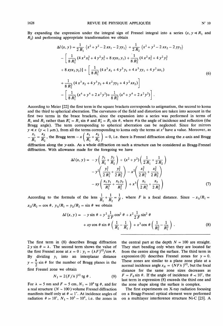
By expanding the expression under the integral sign of Fresnel integral into a series (x, y ~ R1 andR2) and performing appropriate transformation we obtain
According to Meier [22] the first term in the square brackets corresponds to astigmatism, the second to komaand the third to spherical aberration. The curvatures of the field and distortion are taken into account in thefirst two terms in the brace brackets, since the expansion into a series was performed in terms ofR1 and R2 rather than R’1 = Ri sin 03B8 and R’2 = R2 sin 03B8, where (J is the angle of incidence and reflection (theBragg angle). The term corresponding to spherical aberration can be neglected. Since for mirrors
y ~ x (y 1 03BCm), from all the terms corresponding to koma only the terms at x3 have a value. Moreover, as
- x1 R1 = x2 , the Bragg term - x ( xl + x2 = 0, i.e. there is Fresnel diffraction along the x-axis and Braggdiffraction along the y-axis. As a whole diffraction on such a structure can be considered as Bragg-Fresneldiffraction. With allowance made for the foregoing we have
The first term in (8) describes Bragg diffraction2 y sin 03B8 = À. The second term shows the value ofthe first Fresnel zone at x = 0 : y, = (A F)1/2/cos 0.By dividing y1 into an interplanar distance
y = 03BB 2 sin 0 for the number of Bragg planes in the
first Fresnel zone we obtain
For À = 5 nm and F = 5 cm, NI = 104 tg 0, and fora real structure (N ~ 100 ) volume Fresnel diffractionmanifests itself only at 03B8 10. At incidence angles ofradiation 0 > 10°, N, - 10’ _ 104, i.e. the zones in
the central part at the depth N = 100 are straight.They start bending only when they are located farfrom the centre along the surface. The third term inexpression (8) describes Fresnel zones for y = 0.
These zones are similar to a plane zone plate at anormal incidence angle xN = (NFA )1/2, but the focaldistance for the same zone sizes decreases as
F = Fo sin 03B8. If the angle of incidence 0 10°, thelast term in expression (8) exceeds the third one andthe zone shape along the surface is complex.The first experiments on X-ray radiation focusing
on a Bragg-Fresnel optical element were performedon a multilayer interference structure Ni-C [23]. A

1629
profile for amplitude of the X-ray wave front wasfabricated in a multilayer interference mirror. Forphase modulation a gold layer of ~ 300 A thick wasdeposited on the multilayer mirror surface alongeven Fresnel zones. An X-ray tube with a linearfocus and Fe anode was used as a source of X-rayradiation. A slit of - 50 03BCm is placed behind thetube. An optical element is fixed in a goniometrichead at a distance of 18 cm from the slit. When thecentral zone is 180 03BCm and the angle of incident onthe mirror surface is 1.3°, the demagnified image ofthe slit was observed at a distance of 1.7 cm from a
focusing element. Holographic plates (Mikrat) witha self resolution of - 0.2 ktm were used as a recorder.
Figure 8 gives a densitogram of the slit image in theregion of the spectrum typical line FeKa. The size ofthe image slit - 50 03BCm corresponds to a demagnifi-cation in the optical experimental scheme. Forradiation with a wavelength of 0.154 nm focusingwas obtained on a Si profiled crystal in the sameexperimental arrangement [24, 25]. Figure 9 showsthe ellipsoidal zone plate made from multilayermirror by electron-beam lithography and, ion-beametching.
Fig. 8. - Densitigram of the slit image (pointed by anarrowed line) in focusing on a profiles multilayer mirror(À = 1.96 A ).
Volume diffraction of X-ray radiation gives a
possibility not only to perform beam focusing butalso to modulate it with space and time. For
example, interaction between an X-ray wave and asurface - acoustic wave propagating along a mul-tilayer structure permits obtaining rather strongdiffraction reflex. Spatial position of this reflex
depends on the frequency of an acoustic wave.
Figure 10 shows intensity distribution in the far fieldof diffraction during reflection from a multilayermirror modulated by the surface acoustic wave [26].At the amplitude of a surface deformation of 0.4 nmthe efficiency of a diffraction order on the
wavelength 0.196 nm was - 10 %.
Fig. 9. - Bragg-Fresnel optical element made from a
multilayer mirror by electron-beam lithography, and ion-beam etching.
Fig. 10. - Radiation intensity distribution in the far fieldin diffraction on a multilayer structure modulated by anacoustic wave.
Conclusion.
The achievements in microstructure fabrication tech-
nology permit the resolution of plane optical ele-ments based on Fresnel zone plates to approach atheoretical resolution limit caused by the effects ofvolume diffraction. The latest advances in multilayerinterference structure fabrication, microstructuringtechnology and in fabrication of smooth surfaces of agiven form enable us to reach a wavelength up to
1630
03BB ~ 0.5 nm and to make the theoretical resolution
limit closer to the value of a wavelength throughdesigning volume optical elements with allowancemade for the effects of three-dimensional diffraction.The results obtained for X-ray radiation focusing(03BB ~ 0.2 nm ) on a profiled multilayer mirror areexpected to ensure progress in the development ofX-ray optics. X-Ray optical elements on profiledmultilayer mirrors are likely to find increasing appli-cation in high resolution image transmission in
scanning microscopy and photoelectron spec-
troscopy. They can also be used as highly efficientfocusing monochromators of an X-ray wavelengthrange.
Small angles of incidence on plane profiled mirrorsare most effective for the range of X-ray radiationwith a short wavelength (- 0.5 nm). Since the anglesare very small, the effect of aberrations is very
profound and can be eliminated for one point bycalculating a profile in a multilayer coating with
regard to aberration. However, the visual field is
very small under these conditions. Hence, such
optical elements can be used to advantage when onlyradiation focusing is required, for instance, for
scanning microscopy or for scanning photoelectronspectroscopy. The application of profiled mirrors onspherical substrates at incidence angles close to
normal (03B8 ~ 80°) is promising for the soft
wavelength range 03BB ~ 5 nm. Aberrations at such
angles are small and can be almost completelyeliminated by means of submicron technology for agreater visual field. Optical elements for nearlynormal incidence show promise when used for imagetransmission.
Acknowledgments.
We thank S. V. Gaponov, N. N. Salashchenko foruseful discussion of this work, as well as N. V.
Gornakova for microlithography process.
References
[1] KIRKPATRICK, P., BAEZ, A. V. 38 (1948) 766.[2] JENTZSCH, F., Phys. Z. 30 (1929) 268.[3] WOLTER, H., Ann. Phys. 10 (1952) 94, 286.[4] BAEZ, A. V., JOSA 51 (1961) 405 ; 42 (1952) 756.[5] CEGLIO, N. M., AIP Conf. Proc. N 75 (1981) 210.[6] KIRZ, J., RARBACK, H., Rev. Sci. Instrum. 56 (1)
(1985) 1.
[7] RUDOLPH, D., SCHMAHL, G., Ann. N.Y. Acad. Sci.342 (1980) 94.
[8] UNDERWOOD, J. H., ATWOOD, D. T., Phys. Today(April 1984) 44.
[9] HENKE, B. L. et al., AIP Conf. Proc. 75 (1981) 340.[10] ARISTOV, V. V., SHULAKOV, E. V., Kristallografiya
(1987) in press.[11] UNDERWOOD, J. H., BARBEE, T. W., Appl. Opt. 25
(1986) 11, 1730.[12] UNDERWOOD, J. H., BARBEE, T. W., Nature 294
(1981) 429.[13] GAPONOV, S. V., GUSEV, S. A., PLATONOV, Yu.
Ya., SALASHCHENKO, N. N., GLUSKIN, E. S.,Pisma Zh. Eksp. Teor. Fiz. 9 (1983) 4, 208.
[14] LOVAS, I., et al., Proc. SPIE 316 (1980) 90.[15] SPILLER, E., Scanned Image Microscopy, Ed. E. Ash
(Academic, New York) 1980, p. 369.[16] HAELBICH, R., Scanned Image Microscopy, Ed.
E. Ash (Academic, New York) 1980, p. 413.[17] ARISTOV, V. V., SHEKHTMAN, V. Sh., Usp Fiz.
Nauk 104 (1971) 1, 51 (in Russian).
[18] COWLY, J. M., Diffraction Physics (North-Holland,Amsterdam) 1975.
[19] SHULAKOV, E. V., ARISTOV, V. V., Acta Crystallogr.A 38 (1982) 454.
[20] CEGLIO, N. M., STEARNS, D. G., HAWRYLUK,A. M., Applications of Thin-Film MultilayeredStructures to Figured X-Ray Optics, SPIE 563(1985) 360-366.
[21] ARISTOV, V. V., SHULAKOV, E. V., Preprint, Cher-nogolovka (1987) ; Opt. Commun. (to be pub-lished).
[22] MEIER, R. W. 55 (1965) 987.[23] ARISTOV, V. V., GAPONOV, S. V., GENKIN, V. M.,
GORBATOV, Yu. A., ERKO, A. I., MARTYNOV,V. V., MATVEEVA, L. A., SALASHCHENKO,N. N., FRAERMAN, A. A., JETP Lett. 44 (1986)4, 207.
[24] ARISTOV, V. V., BASOV, Yu. A., SNIGIREV, A. A.,Pisma Zh. Eksp. Teor. Fiz. 13 (1987) 2, 144 (inRussian).
[25] ARISTOV, V. V., SNIGIREV, A. A., BASOV, Yu. A.,NIKULIN, A. Yu., AIP Conf. Proc. 147 (1986)253.
[26] ARISTOV, V. V., VERESCHAGIN, G. V., ERKO,A. I., MATVEEVA, L. A., ROSCHUPKIN, D. V.,Pisma Zh. Eksp. Teor. Fiz. 13, 21 (1987) 1288(in Russian).