primljen / received: 16.2.2017. modelling heat loss ... · double skin façade (dsf) is a common...
TRANSCRIPT
Građevinar 11/2018
931GRAĐEVINAR 70 (2018) 11, 931-942
DOI: https://doi.org/10.14256/JCE.2021.2017
Modelling heat loss through multi storey double skin façade
as preliminaries for an energy efficient control strategy
Primljen / Received: 16.2.2017.
Ispravljen / Corrected: 20.6.2018.
Prihvaćen / Accepted: 3.7.2018.
Dostupno online / Available online: 10.12.2018.
AuthorsPreliminary note
Zdravko Eškinja, Stanko Ružić, Ognjen Kuljača
Modelling heat loss through multi storey double skin façade as preliminaries for an energy efficient control strategy
The paper introduces a novel strategy to improve energy consumption by applying new technical solution in Double Skin Façade (DSF) systems. The strategy is based on equalizing thermal loss through all elements of the envelope, but without direct action on interior zone. The focus of this study is in modelling as preliminary action before designing an efficient control strategy through Artificial Neural Network (ANN) based on Lyapunov-like tuning. Results of other experiments will justify the usage of this simplified differential description in further control study of DSF dynamics.
Ključne riječi:multi storey double skin façade, dynamic modelling, numerical simulation, automatic control
Prethodno priopćenjeZdravko Eškinja, Stanko Ružić, Ognjen Kuljača
Modeliranje toplinskih gubitaka višekatne dvoslojne fasade s ciljem kvalifikacije energetski djelotvorne strategije upravljanja
U radu je predstavljena alternativna strategija poboljšanja energetske učinkovitosti primjenom novih tehničkih rješenja u sustavima dvoslojnih fasada (eng. Double Skin Façade, DSF). Istraživanje je fokusirano na model s ciljem kvalifikacije djelotvorne strategije upravljanja koja koristi sustav neuronskih mreža (ANN) i podešavanje prilagođenom Ljapunovom metodom. Rezultati provedenih istraživanja su opravdali upotrebu jednostavnih diferencijalnih jednadžbi u daljnjem istraživanju upravljanja dinamikom DSF-a.
Ključne riječi:višekatna dvoslojna fasada, dinamičko modeliranje, numeričke simulacije, automatsko upravljanje
Vorherige MitteilungZdravko Eškinja, Stanko Ružić, Ognjen Kuljača
Modellierung thermischer Verluste bei mehrstöckigen Doppelfassaden mit dem Ziel der Qualifizierung einer energieeffizienten Managementstrategie
In der Abhandlung wird eine alternative Strategie der Verbesserung der Energieeffizienz durch Anwendung neuer technischer Lösungen bei Doppelfassadensystemen vorgestellt (engl. Double Skin Facade, DSF). Die Untersuchung fokussiert sich auf das Modell mit dem Ziel, eine wirksame Managementstrategie zu qualifizieren, die das System neuronaler Netzwerke (ANN) sowie die Einstellung mithilfe der angepassten Lyapunov-Methode anwendet. Die Ergebnisse der durchgeführten Untersuchungen rechtfertigen die Anwendung einfacher Differenzialgleichungen bei der weiteren Untersuchung des Dynamikmanagements des DSF.
Schlüsselwörter:mehrstöckige Doppelfassade, DSF, dynamische Modellierung, nummerische Simulation, automatisches Management
Zdravko Eškinja, MEEUniversity of ZagrebFaculty of Electrical Engineering and [email protected]
Stanko Ružić, PhD. EEBrodarski Institute, [email protected]
Ognjen Kuljača, PhD. El.

Građevinar 11/2018
932 GRAĐEVINAR 70 (2018) 11, 931-942
Zdravko Eškinja, Stanko Ružić, Ognjen Kuljača
1. Introduction
Double Skin Façade (DSF) is a common enclosure type in office buildings and it’s efficiency was a research topic of numerous studies. Thanks to results of these researches, dynamics in DSF systems is well known nowadays, e.g. [1-4]. Still, designing an active and regulated DSF is quite a challenge. The main reason lies in low observability of the systems, while complex identification, high non-linearity and interdisciplinarity further complicate the effort. In order to concentrate on the issue, only simplified DSF system will be discussed in this paper. Also, a novel control strategy of DSF system will be introduced. Unlike other solutions, this control method tries to directly improve energy efficiency of its critical parts, rather than optimise the conditioning system. Total energy efficiency of building with DSF system will be increased in case of using available thermal mass with higher energy level as an input load for DSF’s cavity. Term available in this context has a meaning of no additional financial costs. Also, in control theory of the active DSF system, there is a practical problem how to effectively regulate heat input without precise heat flow information [5-7]. In our case, the question is about heating the air and injecting it into the cavity of glazed planes, when task is to equalize the heat loss between all vertical planes in the building’s zone.The main goal is to develop a suitable model to enable Artificial Neural Network (ANN) control as described in [8-12]. As shown by [8] and others, ANN is universal approximator. That means it can approximate every smooth function with desired accuracy. The goal is the approximation and control of a system as a whole, not certain parameters, as in classical adaptive control. It can be said that this is a model free approach to development of control system. However this is not entirely accurate. There are certain preconditions to enable such control approach. The main precondition is the stability of controlled system in open loop or at least passivity of such system, [13, 14]. Therefore it is required to analyse and model DSF system in a form suitable for showing its stability (passivity), so to show that ANN control is feasible. This is the goal of this paper thus the main concentration is on system behaviour and not on detailed parameter identification.A novelty is requirement of constant active control in DSF systems. First step in designing the control strategy is to mathematically describe the system. Instead of starting from zero, our idea was to use a model implemented in one of established simulation environments. In this way, modelling is concentrated on specific DSF dynamics sparing huge effort needed for other building elements. Most of the standard building simulation tools (e.g., EnergyPlus®, ESP - r ®, TrnSys®, EDSL Tas®, IDA ICE®, VA 114®, BSim®) developed for conventional building envelopes cannot accurately describe the transient heat and mass transfer phenomena that occur in the complex threedimensional (3-D) geometry of DSFs, as concluded by [15]. Therefore, comparing to real system, significant deviations are expected. One solution
is in more complex control where adaptive algorithms would compensate these drawbacks.
Figure 1. Segment in DSF building
2. Modelling dynamics in DSF cavity
Figure 1 represents one segment of multi storey DSF building used as test structure for this research. Corresponding heat transfer equation, according to [16], is a three dimensional parabolic partial differential equation and the only known way to numerically calculate the solution is to make some approximations. Author’s choice are thermal networks. Such model is described in details in [17] and is skipped here for brevity and to avoid unnecessary multiplications of already published and available research. In short, heat flows are analogue to currents (Φcg - heat from all common heat gains, Φcgr, heat from radiation, Φxy - heat from exterior surface etc.), temperatures nodes to potentials (Tca - Cavity air temperature, Tx - inside surface temperature) heat loss coefficients to resistors (Lxa- coefficient beetwen Tx and Ta) and thermal capacity to electrical one (Cca - heat storage coefficient). With such approach, authors avoided complex modelling, but also radical simplifications as in engineering standards and handbooks i.e. [18-21]. In huge scope of simulation tools, [22], the most suitable choice was HAMBASE model. The model was subject to numerical and empirical analysis, [17]. Numerical analysis consisted of comparative testing and analytical verification. For comparative testing North American standard called ASHRAE Bestest is used, [23].Thermal, hygric and fluid dynamics are mutually correlated. These dependences are significantly non-linear, so in control sense, it is desirable to look for areas and conditions where linearisation gives best results. Required system response data is acquired through repeatable experiments in controllable environment. Commonly large scale simulators are used for this purpose, [24], but such approach is quite time and resource consuming. Therefore, dynamics described in this work is tested through experiments on scaled model in completely observable and thermally controlled

Građevinar 11/2018
933GRAĐEVINAR 70 (2018) 11, 931-942
Modelling heat loss through multi storey double skin façade as preliminaries for an energy efficient control strategy
environment. Using scaled models is not so common practice in civil engineering, but the control of thermo-dynamics is also not common. We are aware that stationary results of real and scaled object will not have satisfactory resemblance, but resemblance of dynamic behaviour will be achieved, as shown by [25]. Practice of multimillion dollar investments, as stated in by [26], is to compare simulated and measured results before building and even in the building phase, so called commissioning phase, in order to calibrate model and correct design if needed.
2.1. Thermal dynamics
The smallest entity of the building is a zone. Zone is a room with almost identical conditions: temperature, relative humidity and climate control. Thermo-dynamic system of two zones: cavity and interior, is analysed from the standpoint of control. System representation will be set in a state-space equation form to integrate non-liner function. Another assumption is needed to be satisfied before proceeding any further. There is no air infiltration from other zones, or through open windows or doors. In order to investigate possibility of using renewable thermal sources garage is analysed as thermal storage [27].The improvement of building’s energy efficiency lies in multifunctional usage of DSF. According to [17], DSF may be modelled as a zone with additional heat input. This method will be used in numeric model simulation and stability analyses. DSF may be also modelled as a zone coated with single layered wall. By applying the analogy of thermal network, dynamics in DSF may be described as a multilayer wall. For both wall and DSF, the governing differential equations for heat flow with boundary conditions are linearised in working area. Because of different behaviour on different frequencies, the equation is split in cyclic admittance (1) and transmittance (2) part:
(1)
(2)
gdje
(3)
kt1 = t1t2 kt1 = t1 + t2
Φx is heat directed to the DSF, and Φxy is heat transmitted through the DSF. Uxy is total thermal transmittance (W/(m2K)) of the DSF. Cx1 and Cx2 are heat capacities of interior cavity surface. Lx1 and Lx2 are coupling coefficients. Axy is a surface of observed element. t1and t2 are time parameters of the heat transmittance. td is delay (time lag) of temperature difference input that causes an unavoidable non-linearity in heat flow. All of these coefficients cannot be measured, so they are found by minimizing the error function of the exact solution with the model solution, [28]. Variable Txy is temperature difference between resultant surface temperature Tx and exterior air temperature Ty. Ty may be measured, and Tx may be substituted with admittance part of system equation (1).
(4)
where Tca is cavity air temperature, Cca is heat storage coefficient of cavity air(J/K), Lxa is heat loss coefficient from cavity to glass surface and Φcg is heat flow as result of all common heat gains in the system (see Figure 1).Transmittance part of the thermo dynamics described with (2) may be transformed into:
(5)
by using substitution of Tx from (4). Well known form of differential equation is then created easily:
(6)
or in shorter form:
(7)
where:

Građevinar 11/2018
934 GRAĐEVINAR 70 (2018) 11, 931-942
Zdravko Eškinja, Stanko Ružić, Ognjen Kuljača
,
, (8)
The function Φaux(t-td) represents external disturbance to the system. If there are no disturbances, the function has fixed values. It is considered that the heat loss through the DSF is only the transmitted heat and not the admitted one, so the system output may be Φxy. The system input should be the control variable. In the case of DSF with input air, control variable is cavity’s input heat flow. In order to write more familiar form of controlled system we may introduce control variable u and output variable y.
(9)
where:
, , (10)
Heat input through the air loaded into cavity may be modelled as a first order differential function, [17]:
(11)
Φd2ca is a heat flow to new mixed air that is the result of loading additional air mass into the cavity. Relation (11) is valid only under assumption of ideal air mass mixing what will be examined in numerical simulations presented in Section 3. Before adding substitution (11), equation (7) is differentiated and a new third-order function is gained:
(12)
And finally:
(13)
where:
(14)
2.2. State space representation
Equation (9) is transformed to state space representation using standard to obtain state space forms ([29] in Section 8.6.1).
(15)
where:
(16)
State space vector elements x1 and x2, and its derivative and are described as:
x1(t) = y(t) = Φxy(t)
(t) = x2(t) + b1u1(t - td) (17)
(t) = (b0 - 1 - a1b1)u1(t - td) - a0x1(t) - a1x2(t) - u2(t - td)
State space form of the system where one control variable is also heat input is derived from (13):
(18)
where:
(19)
Vector elements are described as:
x1(t) = y(t) = Φxy(t)
(t) = x2(t) + c2u1(t - td)

Građevinar 11/2018
935GRAĐEVINAR 70 (2018) 11, 931-942
Modelling heat loss through multi storey double skin façade as preliminaries for an energy efficient control strategy
(t) = x3(t) + (c1 - a1c2)u1(t - td) - u2(t - td)
(t) = - a0x2(t) - a1x3(t) + a1u2(t - td) (20)
+
State space equation presented in (18) is used to propose Ljapunov function candidate for open loop system as in (21).
(21)
where P is symmetric positive definite matrix defined by the system and B is a control and disturbance matrix conditioned by user. In this case, deviations caused from assumptions will influence the value of the bounding and not the Lyapunov function. As in similar system’s mentioned above, the control law through neural network is derived in such way that tuning function for weights ensures the continued stability of the system, [11, 13, 30].The fact that this is possible, is due to stability of neural network controlled system (again as given in [8]) and universal approximation ability of ANN as proved in [31]. But, before finding proper tuning function, capable of ensuring the negative derivation of Lyapunov candidate, it should be established that observed system’s behaviour is continuous and bounded under certain conditions. Following analysis will justify the usage of the simplified model as a base for adaptive neural network control method that requires no pre-learning.
2.3. Airflow dynamics
Influence of airflow on thermal dynamics in DSF is significant and has been taken into account when there is mechanical airflow in the cavity. The cavity does not have typical ventilation, but has airflow input on-demand. While air mass is being injected into cavity, the airflow influence is modelled as air flow resistance that is added to thermal network that describes the DSF. As it is assumed that the air is fully mixed (no temperature stratification), the air flow resistance may be expressed as where cp is specific heat of air and Qm is air mass flow (kg/m3) in the cavity. This is a huge simplification of very complicated process, but [17] claims the real problem is not simplification, it is uncertainty about input quantities. In our case these uncertainties are: the airflow rate and the coefficients at the cavity surfaces. Behavioural characteristics are preserved under observed domain. This is confirmed by experimental tests, which is the goal of developing a model suitable for Artificial Neural Network (ANN) control.
3. Numerical simulations
HAMBASE was used as a basis for numerical analysis. Limitation of HAMBASE was recognized and the model was adapted for numerical analysis in a state space form applicable for control system development. The necessary changes and choice of applicable numerical solver were made in code. Changes are described with given mathematics in paper. Detailed description of the amended software code are beyond the scope of this paper.
3.1. Thermo-dynamics Simulation
At start, the influence of the external air temperature upon the building behaviour is analyzed using Matlab/Simulink and toolbox HAMBASE. Input of numerical analysis are hourly values of measured data of weather station in Zagreb, Croatia, from 1970. Solar, furniture, bio-environmental and all other disturbances are excluded such as in [32]. Dimensions of the building in numerical model are similar with dimensions of experimental model, which is described in Section 4. Here, dimensions are variated from scale 1:1 to scale 1:18. Four variations are exposed to same thermal conditions in a period of 6 days. Temperature of the air in the building and heat were observed. Simulations ended up with quite different results. Results are shown in Figure 2.
Figure 2. Influence of dimension variance in scale to air temperature in the zone
The increasement of building’s dimensions caused disproportionally larger energy flow between interior and exterior space during same temperature variations. However, this is expected because of exponentially more volume. Temperature value in the daily peak for 1:1 scale is questionable. This peak is double comparing to next lower dimension, and the heat loss is not that high for the same peak. The simulation result shows impossibility to use standard energy prediction in scaled models As aim of the modelling is not classical prediction,

Građevinar 11/2018
936 GRAĐEVINAR 70 (2018) 11, 931-942
Zdravko Eškinja, Stanko Ružić, Ognjen Kuljača
authors would not give further analysis, but conclude how HAMBASE, or any similar model is not an option for dimension-variant regulation method.
3.2. Airflow simulation and analysis
Based on experimental results as shown in next section, maximum input air speed amounts 0.42 m/s on duct opening and 1.02 m/s directly after the fan. Considering these values as input, CFD (Computational Fluid Dynamics) analysis was successfully performed in Ansys Fluent v12. The air flow behaviour have been obtained for both DSF configurations: with and without shaft on the diagonally opposite side of the air input. The simulation was influenced by the standard procedures which are defining the geometry of the tested cell, meshing, fluid properties, boundary conditions, solver settings and solution methods. The results are obtained from CFD post which is a common post-processor feature of fluid dynamics simulation environment. Figure 3 shows the CFD stream plots of the air velocity inside the DSF’s cavity. It can be seen that the air distribution pattern in the area of low speed flows behaves fairly well for the purpose of linearisation. Heat loss reduction is lower when the shutter is closed.
Figure 3. CFD - air flow velocity vectors and contours
4. Experimental simulation
Experimental simulation has multiple purposes: collecting data to define initial conditions of the system and analysis of numerical model. Measurements took place from June till August 2015. at electro-mechanical laboratory of Brodarski institute. Thermal measurements were set up under EU building codes, [30]. There is no official standard for measuring dynamic characteristics of DSF, so we used experience from other researches on the similar topic: [1, 5, 34, 35]. Experiments were obtained on experimental model shown in Figure 6. The model has been made in scale 1:18, and it represents ground floor of the building. All materials used while modelling are equal to those in civil engineering: expanded polystyrene, wall paint, glass, concrete and bitumen layer.
4.1. Equipment used in experiment
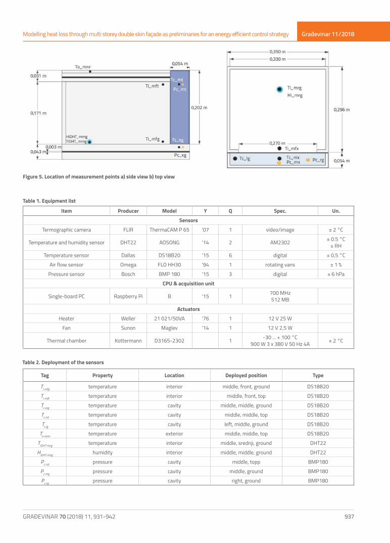
For carrying out the experiment different instruments and actuators are needed. The equipment used in the experiment is listed in Table 1 together with each item’s producer, model, year of production (Y), quantity (Q), specification (Spec.) and measurement uncertainty (Un.). Sensors are used to collect data. Heater and ventilator are used as a source of conditioned air mass. A thermal chamber maintained desired environmental temperatures. Control Process Unit (CPU) managed data acquisition and control. Instead of using one of standard industrial controllers, sensor data acquisition is obtained by developing a simple low-cost unit based on Raspberry Pi. See Figure 4.
Figure 4. Low cost single board computer - Raspberry Pi
Main motivation for such decision is to introduce well-know and well-spread hardware and software into the industry. For sure, its hardware is not robust and its software is not optimised but two things pop out as benefits: cost-effective value is on very high level and open-source environment gives great promise about persistent maintenance. In addition, observed and controlled variables are not time critical, without any financial or safety risk if the system fails.
4.2. Measurement Set-up
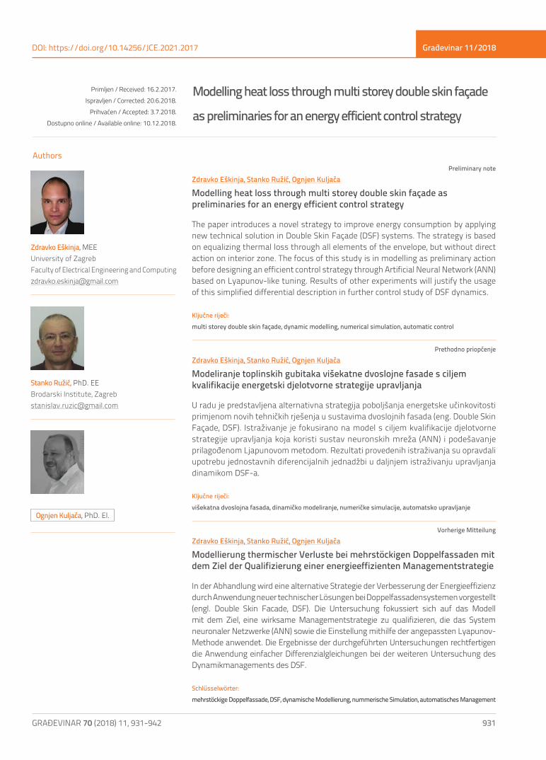
Figure 5 represents side-view and top-view projections of the model where the location of measurement points are denoted. Labelled dots stand for sensors, whose purpose, position and type are described in Table 2. Due to projection of 3D to 2D space, some dots represent more than one sensor. At these positions sensor’s labels contain letter x that may have multiple meanings. e.g. Tc-mx represents Tc-mg and Tc-mt.
4.3. Experiments in Thermal chamber
During the experimental measurements, exterior air temperatures varied between -30°C and +30°C and the interior air temperature was not conditioned. The experiments were carried out using thermal chamber to regulate exterior
Građevinar 11/2018
937GRAĐEVINAR 70 (2018) 11, 931-942
Modelling heat loss through multi storey double skin façade as preliminaries for an energy efficient control strategy
Figure 5. Location of measurement points a) side view b) top view
Item Producer Model Y Q Spec. Un.
Sensors
Termographic camera FLIR ThermaCAM P 65 ‘07 1 video/image ± 2 °C
Temperature and humidity sensor DHT22 AOSONG ‘14 2 AM2302 ± 0.5 °C± RH
Temperature sensor Dallas DS18B20 ‘15 6 digital ± 0,5 °C
Air flow sensor Omega FLO HH30 ‘94 1 rotating vans ± 1 %
Pressure sensor Bosch BMP 180 ‘15 3 digital ± 6 hPa
CPU & acquisition unit
Single-board PC Raspberry Pi B ‘15 1 700 MHz512 MB
Actuators
Heater Weller 21 021/50VA ‘76 1 12 V 25 W
Fan Sunon Maglev ‘14 1 12 V 2,5 W
Thermal chamber Kottermann D3165-2302 1 -30 ... + 100 °C900 W 3 x 380 V 50 Hz 4A ± 2 °C
Table 1. Equipment list
Table 2. Deployment of the sensors
Tag Property Location Deployed position Type
Ti-mfg temperature interior middle, front, ground DS18B20
Ti-mft temperature interior middle, front, top DS18B20
Tc-mg temperature cavity middle, middle, ground DS18B20
Tc-mt temperature cavity middle, middle, top DS18B20
Tc-lg temperature cavity left, middle, ground DS18B20
To-mmr temperature exterior middle, middle, top DS18B20
TiDHT-mng temperature interior middle, srednji, ground DHT22
HiDHT-mng humidity interior middle, middle, ground DHT22
Pc-mt pressure cavity middle, topp BMP180
Pc-mg pressure cavity middle, ground BMP180
Pc-rg pressure cavity right, ground BMP180

Građevinar 11/2018
938 GRAĐEVINAR 70 (2018) 11, 931-942
Zdravko Eškinja, Stanko Ružić, Ognjen Kuljača
air temperature, and fan with heater to deliver warm air. Experiment set up is shown in Figure 6.
Figure 6. Experimental model placed in thermal chamber
The first test was performed to get general image of dynamic properties of the system. Tested segment was excited with sinusoidal thermal input (To-mmr), which is shown in Figure 7, together with resulted response. All sensors show almost equal values in initial state around 22 °C. Responses of air temperatures (labeled as in Table 2) are clearly grouped by their belonging to one of the zones. The difference between air temperatures, measured on different positions in the cavity, is very small. That difference is little more significant in the interior zone. In both cases, these deviations are practically negligible compared to the values of adjacent and exterior zone. In second part of the test, the model was cooled by equal steps. Exterior air temperature had cascading value decrease, but this effect did not pass into zones. These results gives an indication of possibility to linearise this particular behaviour.Figure 8 presents cavity air and interior air temperature responses on increasing thermal steps with the same relative value of 10 °C. Steps refer to a mathematical staircase functions of input to thermal chamber. Thermal chamber generates the change of exterior temperature which directly excite interior temperatures. Each figure shows five different responses of interior temperature. All responses are set to the unit scale in order to analyse behaviour under different temperature ranges. Temperature range is noted in label of each signal. Results are very similar for both
temperature variables, indicating that thermal resistance of the DSF system in these conditions is constant. Accordingly, temperature does not affect DSF properties to the significant degree, so system may be observed like a multilayer wall as stated in Section 2.1.
Figure 7. Air temperatures of different zones as response on dynamic heat flow input in the thermal chamber
4.4. Airflow Experiments
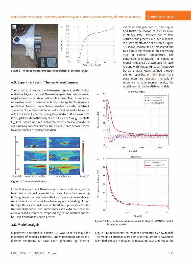
Research of [34] demonstrated extreme difficulty of measuring air flow in naturally ventilated space. Small dimensions of cavity of scaled model do not allow most of direct measurements. Miniature pressure sensors from Table 1 were installed, but testing yielded very unsatisfactory results. Air flows caused by mechanical ventilation are much easier to measure. The most common way to get air flow is to measure air speed and then estimate airflow. Air speed is measured directly after the fan and on the duct opening as in Figure 9a. From Figure 9b it is evident that the airflow behaviour of the hot-air input may be linearised around selected working point. This data is used as an input for numerical simulation described in Section 3.
Figure 8. Response of air temperature due to different increasing steps: a) cavity air; b) interior air
Građevinar 11/2018
939GRAĐEVINAR 70 (2018) 11, 931-942
Modelling heat loss through multi storey double skin façade as preliminaries for an energy efficient control strategy
4.5. Experiments with Thermo-visual Camera
Thermo-visual camera is used to examine temperature distribution under direct dynamic air inlet. These experiments has been conceived to get an information about airflow influence on thermal behaviour where direct airflow measurements cannot be applied. Experimental model was placed in front of thermovisual camera listed in Table 1. The focus of the camera is set on a duct that connects the model with the source of warm air. During the period of 180 s, the warm air is being delivered into the cavity of the DSF directly through the shaft. Figure 10 shows infra-red photos that have been shot periodically while running two experiments. The only difference between these two experiments is the heater position.
Figure 10. Thermo-visual tests
In the first experiment there is a gap of one centimetre, so the heat flow in the duct is greater on the right side. By comparing both figures, it can be observed that a proper experiment design must be ensured in order to achieve equally spreading of heat through the air channel. Non-centered set up causes complex thermal distribution and sometimes even extreme nonlinear airflow called turbulence. Proposed regulation method cannot be used if such behaviour is present.
4.6. Model analysis
Experiment described in Section 4.3 was used as input for inspection of model’s behaviour under presented conditions. Exterior temperatures have been generated by thermal
chamber with precision of one degree and that’s the reason of its oscillation in steady state. However, due to slow nature of the process, resulted response is quite smooth and not affected. Figure 11 shows comparison of measured and two simulated response on decreasing step of exterior temperature. The parameter identification of simulated model (HAMBASE), shown on left image, is done with Matlab function fminsearch by using parameters defined through element specification [36]. Even if this parameters are adjusted manually in reference to experimental results, the model cannot reach satisfying match.
Figure 9. Air speed measurements: configuration; b) characteristics
Figure 11. Interior temperature response to step: a) HAMBASE model; b) custom model
Figure 11.b represents the response simulated by new model. The model’s equations were same, only parameters have been identified directly in relation to measured data and not to the

Građevinar 11/2018
940 GRAĐEVINAR 70 (2018) 11, 931-942
Zdravko Eškinja, Stanko Ružić, Ognjen Kuljača
Figure 12. Comparison of experimental and simulated response through different regions
Građevinar 11/2018
941GRAĐEVINAR 70 (2018) 11, 931-942
Modelling heat loss through multi storey double skin façade as preliminaries for an energy efficient control strategy
standardised properties of the zone. The result is a satisfyingly low deviation between measured and simulated variables. To justify the usage of the model, an analysis was performed on several different thermal regions. The Figure 12 show response of 6 different parameter sets excited by 3 different steps. Curves on left image represent interior air temperatures and on right they represent errors of transfer functions (TF). Simulated results of different step responses are compared to experimental results.Unlike experimental results, shown in Figure 8, simulated response errors are very variable. The reason is in exceeding the bounding of identification area. Linear equations are not adequate to model observed behaviour, but the order of the transfer function is identical for all cases. The difference is only in parameters what should be solved by adaptive neural network. Adaptive NN Control method used in research [30] does not require exact relations or parameterisation. The number of the highest derivative in a differential equation should be sufficient information required to set up adaptive
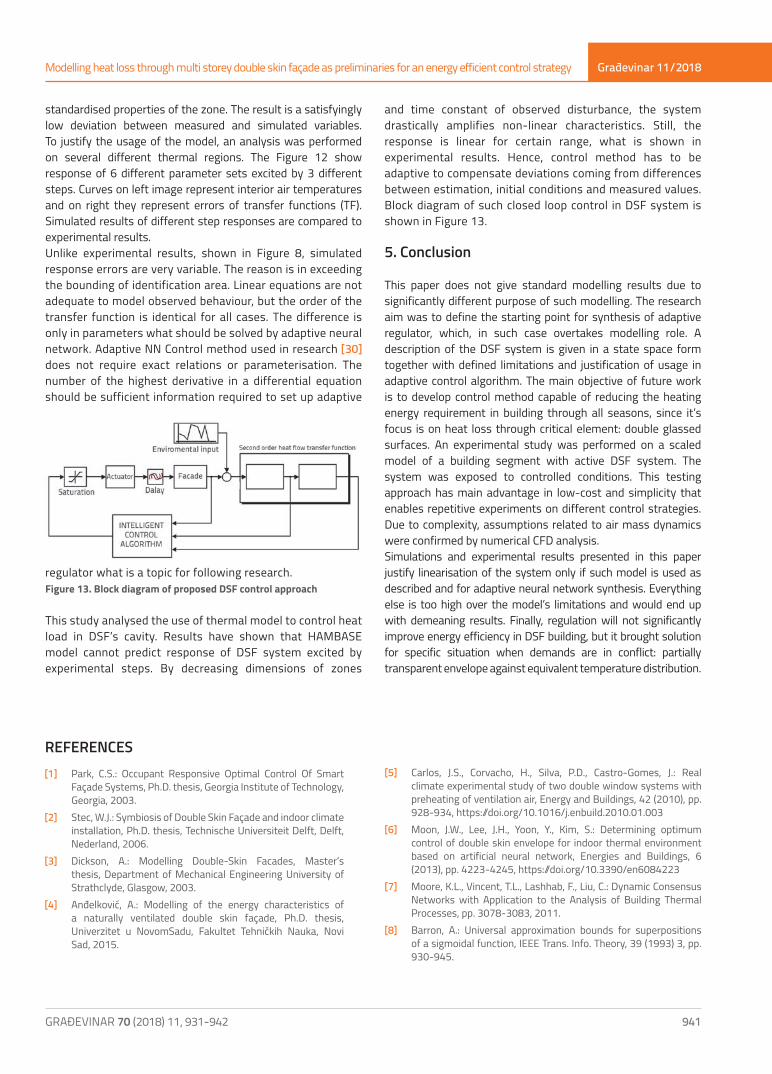
regulator what is a topic for following research.Figure 13. Block diagram of proposed DSF control approach
This study analysed the use of thermal model to control heat load in DSF’s cavity. Results have shown that HAMBASE model cannot predict response of DSF system excited by experimental steps. By decreasing dimensions of zones
and time constant of observed disturbance, the system drastically amplifies non-linear characteristics. Still, the response is linear for certain range, what is shown in experimental results. Hence, control method has to be adaptive to compensate deviations coming from differences between estimation, initial conditions and measured values. Block diagram of such closed loop control in DSF system is shown in Figure 13.
5. Conclusion
This paper does not give standard modelling results due to significantly different purpose of such modelling. The research aim was to define the starting point for synthesis of adaptive regulator, which, in such case overtakes modelling role. A description of the DSF system is given in a state space form together with defined limitations and justification of usage in adaptive control algorithm. The main objective of future work is to develop control method capable of reducing the heating energy requirement in building through all seasons, since it’s focus is on heat loss through critical element: double glassed surfaces. An experimental study was performed on a scaled model of a building segment with active DSF system. The system was exposed to controlled conditions. This testing approach has main advantage in low-cost and simplicity that enables repetitive experiments on different control strategies. Due to complexity, assumptions related to air mass dynamics were confirmed by numerical CFD analysis. Simulations and experimental results presented in this paper justify linearisation of the system only if such model is used as described and for adaptive neural network synthesis. Everything else is too high over the model’s limitations and would end up with demeaning results. Finally, regulation will not significantly improve energy efficiency in DSF building, but it brought solution for specific situation when demands are in conflict: partially transparent envelope against equivalent temperature distribution.
REFERENCES[1] Park, C.S.: Occupant Responsive Optimal Control Of Smart
Façade Systems, Ph.D. thesis, Georgia Institute of Technology, Georgia, 2003.
[2] Stec, W.J.: Symbiosis of Double Skin Façade and indoor climate installation, Ph.D. thesis, Technische Universiteit Delft, Delft, Nederland, 2006.
[3] Dickson, A.: Modelling Double-Skin Facades, Master’s thesis, Department of Mechanical Engineering University of Strathclyde, Glasgow, 2003.
[4] Anđelković, A.: Modelling of the energy characteristics of a naturally ventilated double skin façade, Ph.D. thesis, Univerzitet u NovomSadu, Fakultet Tehničkih Nauka, Novi Sad, 2015.
[5] Carlos, J.S., Corvacho, H., Silva, P.D., Castro-Gomes, J.: Real climate experimental study of two double window systems with preheating of ventilation air, Energy and Buildings, 42 (2010), pp. 928-934, https://doi.org/10.1016/j.enbuild.2010.01.003
[6] Moon, J.W., Lee, J.H., Yoon, Y., Kim, S.: Determining optimum control of double skin envelope for indoor thermal environment based on artificial neural network, Energies and Buildings, 6 (2013), pp. 4223-4245, https://doi.org/10.3390/en6084223
[7] Moore, K.L., Vincent, T.L., Lashhab, F., Liu, C.: Dynamic Consensus Networks with Application to the Analysis of Building Thermal Processes, pp. 3078-3083, 2011.
[8] Barron, A.: Universal approximation bounds for superpositions of a sigmoidal function, IEEE Trans. Info. Theory, 39 (1993) 3, pp. 930-945.

Građevinar 11/2018
942 GRAĐEVINAR 70 (2018) 11, 931-942
Zdravko Eškinja, Stanko Ružić, Ognjen Kuljača
[9] Narendra, K.: Adaptive Control Using Neural Networks in: W.T.Miller, R.S. Sutton, P.J. Werbos (Eds.), Neural Networks for Control, MIT Press, Cambridge, pp. 115-142, 1991.
[10] Lewis, F.L., Liu, K., Yesildirek, A.: Neural Net Robot Controller with Guaranteed Tracking Performance, IEEE Transactions on Neural Networks, 6 (1995) 3, pp. 703-715.
[11] Lewis, F.L., Jagannathan, S., Yeşildirek, A.: Neural Network Control ofRobot Manipulators and Nonlinear Systems, no. ISBN 0-7484-0596-8,Taylor and Francis Inc., 1999.
[12] Kuljaca, O., Lewis, F.L., Horvat, K.: Inteligent control of industrial andpower systems: Adaptive Neural Network and Fuzzy Systems, no. 978-3-8484-8468-3, LAMBERT Academic Publishing, 2012.
[13] Bai, H., Arcak, M., Wen, J.: Cooperative Control Design, ASystematic, Passivity-Based Approach, Springer, 2011, https://doi.org/10.1007/978-1-4614-0014-1
[14] Mukherjee, S., Mishra, S., Wen, J.T.: Building Temperature Control : A Passivity-Based Approach, in: 51st IEEE Conference on Decision and Control, Maui, Hawaii, USA, pp. 6902-6907, 2012, https://doi.org/10.1109/CDC.2012.6426676
[15] Kim, D.W., Park, C.S.: Integrated Control Strategies For Double Skin Systems, in: Proceedings of Building Simulation 2011, 12th Conference of International Building Performance Simulation Association, Sydney, Australia, pp. 601-608, 2011.
[16] Pletcher, R.H., Tannehill, J.C., Anderson, D.: Computational Fluid Mechanics and Heat Transfer, Taylor and Francis Inc., USA, 2011.
[17] deWit, H.M.: Part I Theory: Heat Air and Moisture model for Building And Systems Evaluation, Technische Universiteit Eindhoven, Eindhoven, Nederland, 2009, URL http://www.hambase.org
[18] Pavković, B., Zanki, V.: Handbook for Energy Certification in Buildings, UNDP, Zagreb Croatia. 2010.
[19] Anđelković, A.S., Cvjetković, T.B., Ðaković, D.D., Stojanović, I.H.: The Development of Simple Calculation Model for Energy Performance of Double Skin Facades, Thermal Science, 16 (2012), pp. 251-267, https://doi.org/10.2298/TSCI120201076A
[20] Xianfeng, Z., Junping, F., Xiaoqing, Y.: A simplified mathematical model of heat transfer process in double skin façade, in: 2011 International Conference on Computer Distributed Control and Intelligent Environmental Monitoring, Changsha, Hunan, China, pp. 389-393, 2011, https://doi.org/10.1109/CDCIEM.2011.487
[21] Kämpf, J.H., Robinson, D.: A simplified thermal model to support analysis of urban resource flows, Energy and Buildings, 39 (2007) 4, pp. 445-453.
[22] Woloszyn, M., Rode, C.: Tools for performance simulation of heat, air and moisture conditions of whole buildings, Building Simulation, 1 (2008) 1, pp. 5-24.
[23] Brayton, E.R., Aydogan, A.: ANSI/ASHRAE Standard 140-2001 (BESTEST), american Society of Heating, Refrigerating and Air-Conditioning Engineers, 2004, URL https://www.ashrae.org/
[24] Gavan, V., Woloszyn, M., Kuznik, F., Roux, J.J.: Experimental study of a mechanically ventilated double-skin façade with venetian sun-shading device a full-scale investigation in controlled environment., Solar Energy, 84 (2010) 2, pp. 183-195.
[25] Xie, C., Hazzard, E., Nourian, S.: A Green Building Model Kit for Engineering Design, The Concord Consortium, Concord, MA 01742, USA 2012, URL http://concord.org/
[26] Maile, T., Bazjanac, V., Donnell, J.O., Garr, M.: A software tool to compare measured and simulated building energy performance data, in: Proceedings of 12th International IBPSA Conference, Sydney, Australia, 2011.
[27] Ataer, E.: Storage of thermal energy, in energy storage systems, developed under the Auspices of the UNESCO, Eolss Publishers, Oxford, 2006, URL http://www.eolss.net
[28] van Schijndel, A.W.M.: Integrated Heat Air and Moisture Modeling and Simulation, Ph.D. thesis, TechnischeUniversiteit Eindhoven, Eindhoven, Nederland, 2007.
[29] Vukić, Z., Kuljača, Lj.: Automatsko upravljanje - analiza linearnih sustava, no. 953604529-X, Kigen, Zagreb, 2005.
[30] Kuljača, O., Horvat, K., Borović, B.: Design of Adaptive Neural Network Controller for Thermal Power System Frequency Control, Automatika, 52 (2011) 4, pp. 319-328.
[31] Hornik, K., Stinchombe, M., White, H.: Multilayer feedforward networks are universal approximators, Neural Networks, 2 (1989), pp. 359-366, https://doi.org/10.1016/0893-6080(89)90020-8
[32] Mazzarella, L., Pasini, M.: Integration time step issue in mediterranean historic building energy simulation, Energy Procedia, 133 (2017), pp. 53-67, https://doi.org/10.1016/j.egypro.2017.09.371
[33] Laustsen, J.: Energy efficiency requirements in building codes, energy efficiency policies for new buildings, OECD/IEA (March 2008).
[34] Kalyanova, O., Jensen, R.L., Heiselberg, P.: Measurement of Air Flow Rate in a Naturally Ventilated Double Skin Facade, in: Proceedings of Roomvent 2007, Helsinki, Finland, 2007.
[35] Navvab, M.: Full Scale Testing and Computer Simulation of a Double Skin Façade Building, in: Ninth International IBPSA Conference, Montréal, Canada, 2005.
[36] deWit, M.H.: Part II Input and Output: Heat Air and Moisture model for Building And Systems Evaluation, Technische Universiteit Eindhoven, Eindhoven, Nederland (2009), URL http://www.hambase.org