primary beam ex
TRANSCRIPT
Document Ref: SX015a-EN-UK Sheet 1 of 16 Title
Example: Simply supported primary composite beam
Eurocode Ref EN 1993-1-1, EN 1994-1-1 Made by Laurent Narboux Date Nov 2006
CALCULATION SHEET
Checked by Charles King Date Nov 2006
Localized resource for UK
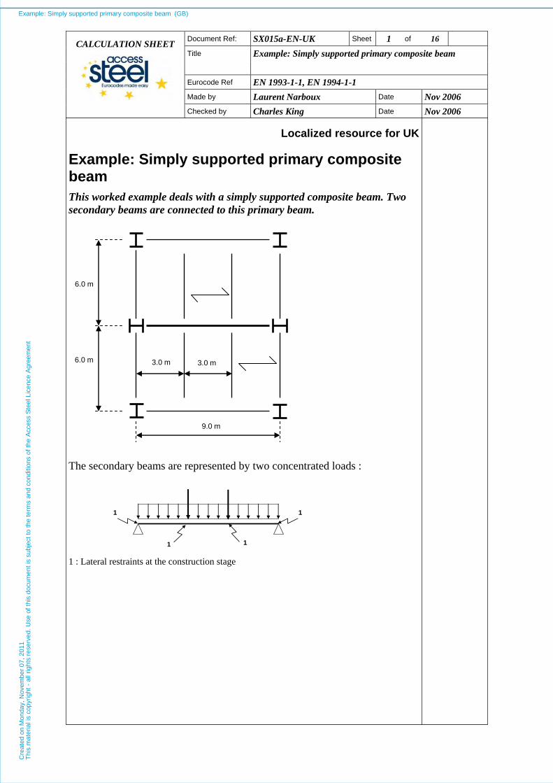
Example: Simply supported primary composite beam This worked example deals with a simply supported composite beam. Two secondary beams are connected to this primary beam.
6.0 m
6.0 m
9.0 m
3.0 m 3.0 m
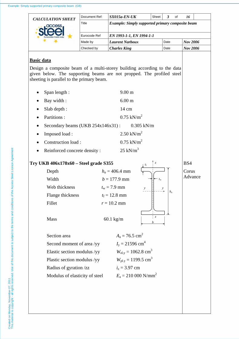
The secondary beams are represented by two concentrated loads :
1 1
1 1 1 : Lateral restraints at the construction stage
Example: Simply supported primary composite beam (GB)C
reat
ed o
n M
onda
y, N
ovem
ber
07, 2
011
Thi
s m
ater
ial i
s co
pyrig
ht -
all
right
s re
serv
ed. U
se o
f thi
s do
cum
ent i
s su
bjec
t to
the
term
s an
d co
nditi
ons
of th
e A
cces
s S
teel
Lic
ence
Agr
eem
ent
Document Ref: SX015a-EN-UK Sheet 2 of 16 Title
Example: Simply supported primary composite beam
Eurocode Ref EN 1993-1-1, EN 1994-1-1 Made by Laurent Narboux Date Nov 2006
CALCULATION SHEET
Checked by Charles King Date Nov 2006
The beam is a UKB profile in bending about the strong axis. This example includes :
- the classification of the cross-section,
- the calculation of the effective width of the concrete flange,
- the calculation of the shear resistance of a headed stud,
- the calculation of the degree of shear connection,
- the calculation of the bending resistance,
- the calculation of the shear resistance,
- the calculation of the longitudinal shear resistance of the slab,
- the calculation of the deflection at serviceability limit state.
This example does not include any shear buckling verification of the web.
Partial factors
• γG = 1.35 (permanent loads)
• γQ = 1.50 (variable loads)
• γM0 = 1.0
• γM1 = 1.0
• γV = 1.25
• γC = 1.5
EN 1990
EN 1993-1-1
§ 6.1 (1)
EN 1994-1-1
§ 6.6.3.1
EN 1992-1-1
Example: Simply supported primary composite beam (GB)C
reat
ed o
n M
onda
y, N
ovem
ber
07, 2
011
Thi
s m
ater
ial i
s co
pyrig
ht -
all
right
s re
serv
ed. U
se o
f thi
s do
cum
ent i
s su
bjec
t to
the
term
s an
d co
nditi
ons
of th
e A
cces
s S
teel
Lic
ence
Agr
eem
ent
Document Ref: SX015a-EN-UK Sheet 3 of 16 Title
Example: Simply supported primary composite beam
Eurocode Ref EN 1993-1-1, EN 1994-1-1 Made by Laurent Narboux Date Nov 2006
CALCULATION SHEET
Checked by Charles King Date Nov 2006
Basic data Design a composite beam of a multi-storey building according to the data given below. The supporting beams are not propped. The profiled steel sheeting is parallel to the primary beam.
• Span length : 9.00 m
• Bay width : 6.00 m
• Slab depth : 14 cm
• Partitions : 0.75 kN/m2
• Secondary beams (UKB 254x146x31) : 0.305 kN/m
• Imposed load : 2.50 kN/m2
• Construction load : 0.75 kN/m2
• Reinforced concrete density : 25 kN/m3
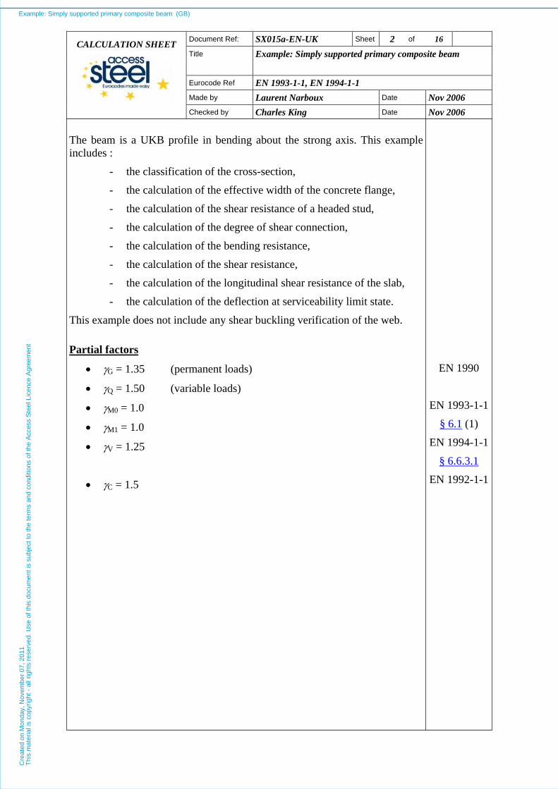
Try UKB 406x178x60 – Steel grade S355
Depth ha = 406.4 mm
Width b = 177.9 mm
Web thickness tw = 7.9 mm
Flange thickness tf = 12.8 mm
Fillet r = 10.2 mm
Mass 60.1 kg/m
z
z
y y
tf
tw
b
ha
BS4
Corus Advance
Section area Aa = 76.5 cm2
Second moment of area /yy Iy = 21596 cm4
Elastic section modulus /yy Wel,y = 1062.8 cm3
Plastic section modulus /yy Wpl.y = 1199.5 cm3
Radius of gyration /zz iz = 3.97 cm
Modulus of elasticity of steel Ea = 210 000 N/mm2
Example: Simply supported primary composite beam (GB)C
reat
ed o
n M
onda
y, N
ovem
ber
07, 2
011
Thi
s m
ater
ial i
s co
pyrig
ht -
all
right
s re
serv
ed. U
se o
f thi
s do
cum
ent i
s su
bjec
t to
the
term
s an
d co
nditi
ons
of th
e A
cces
s S
teel
Lic
ence
Agr
eem
ent

Document Ref: SX015a-EN-UK Sheet 4 of 16 Title
Example: Simply supported primary composite beam
Eurocode Ref EN 1993-1-1, EN 1994-1-1 Made by Laurent Narboux Date Nov 2006
CALCULATION SHEET
Checked by Charles King Date Nov 2006
Profiled steel sheeting Thickness of sheet t = 0.75 mm
Slab depth h = 140 mm
Overall depth of the profiled steel sheeting excluding embossments
hp = 58 mm
b1 = 62 mm b2 = 101 mm e = 207 mm
Connectors Diameter d = 19 mm
Overall nominal height hsc = 100 mm
Ultimate tensile strength fu = 450 N/mm2
Number of studs n = 74 row
(Stud at beam mid-span ignored)
0,5hp
hp
hsc
h
b0
b1 b2
e
Concrete class : C 25/30 Value of the compressive strength at 28 days fck = 25 N/mm2
Secant modulus of elasticity of concrete Ecm = 31 476 N/mm2
EN 1992-1-1
§ 3.1.3
Table 3.1
Example: Simply supported primary composite beam (GB)C
reat
ed o
n M
onda
y, N
ovem
ber
07, 2
011
Thi
s m
ater
ial i
s co
pyrig
ht -
all
right
s re
serv
ed. U
se o
f thi
s do
cum
ent i
s su
bjec
t to
the
term
s an
d co
nditi
ons
of th
e A
cces
s S
teel
Lic
ence
Agr
eem
ent
Document Ref: SX015a-EN-UK Sheet 5 of 16 Title
Example: Simply supported primary composite beam
Eurocode Ref EN 1993-1-1, EN 1994-1-1 Made by Laurent Narboux Date Nov 2006
CALCULATION SHEET
Checked by Charles King Date Nov 2006
Permanent load : To take into account the troughs of the profiled steel sheeting , the weight of the slab for the secondary beams is taken as:
25 × 3.0 × (0.14 – 2
145.0106.0 + ×207.0058.0 ) = 7.86 kN/m
Concentrated loads during the construction stage :
FG = (0.305 + 7.86) × 6.0 = 49 kN
Permanent loads in the final stage :
The value of the concentrated loads on the primary beam is:
FG = (0.305 + 7.86 + 0.75 × 3.0) × 6.0 = 62.49 kN
Self weight of the primary beam :
qG = 9.81 × 60.1 × 10-3 = 0.590 kN/m
Variable load (Imposed load) : Concentrated loads during the construction stage :
FQ = 0.75 × 3.0 × 6.0 = 13.5 kN
Concentrated loads in the final stage:
FQ = 2.5 × 3.0 × 6.0 = 45.0 kN
ULS Combination :
γG FG + γQ FQ = 1.35 × 62.49 + 1.50 × 45.0 = 151.86 kN
γG qG + γQ qQ = 1.35 × 0.59 = 0.797 kN/m
Eq. (6.10) is used. In some countries, the National Annex may specify the use of equations (6.10a) and (6.10b).
EN 1990
§ 6.4.3.2
ULS Combination during the construction stage:
γG FG + γQ FQ = 1.35 × 49 + 1.50 ×13.5 = 86.4 kN
γG qG + γQ qQ = 1.35 × 0.59 = 0.797 kN/m
Example: Simply supported primary composite beam (GB)C
reat
ed o
n M
onda
y, N
ovem
ber
07, 2
011
Thi
s m
ater
ial i
s co
pyrig
ht -
all
right
s re
serv
ed. U
se o
f thi
s do
cum
ent i
s su
bjec
t to
the
term
s an
d co
nditi
ons
of th
e A
cces
s S
teel
Lic
ence
Agr
eem
ent

Document Ref: SX015a-EN-UK Sheet 6 of 16 Title
Example: Simply supported primary composite beam
Eurocode Ref EN 1993-1-1, EN 1994-1-1 Made by Laurent Narboux Date Nov 2006
CALCULATION SHEET
Checked by Charles King Date Nov 2006
Moment diagram
463.6 kNm
M
Maximum moment at mid span :
My,Ed = 3.0 × 151.86 + 0.125 × 0.797 × 9.02 = 463.6 kNm
Maximum moment at mid span (sequence of construction) :
My,Ed = 3.0 × 86.4 + 0.125 × 0.797 × 9.02 = 267.2 kNm
Shear force diagram
V
155.45 kN
Maximum shear force at supports :
Vz,Ed = 151.86 + 0.5 × 0.797 × 9.0 = 155.45 kN
Maximum shear force at supports (sequence of construction) :
Vz,Ed = 86.4 + 0.5 × 0.797 × 9.0 = 90.00 kN
Yield strength
Steel grade S355
The maximum thickness is 12.8 mm < 40 mm, so : fy = 355 N/mm2
Note : The National Annex may impose either the values of fy from the Table 3.1 or the values from the product standard. Does not matter in this case.
EN 1993-1-1
Table 3.1
Section classification :
The parameter ε is derived from the yield strength : 0.81 ][N/mm
235 2y
==f
ε
Note : The classification is made for the non composite beam. For the composite beam the classification is more favourable for the web.
Example: Simply supported primary composite beam (GB)C
reat
ed o
n M
onda
y, N
ovem
ber
07, 2
011
Thi
s m
ater
ial i
s co
pyrig
ht -
all
right
s re
serv
ed. U
se o
f thi
s do
cum
ent i
s su
bjec
t to
the
term
s an
d co
nditi
ons
of th
e A
cces
s S
teel
Lic
ence
Agr
eem
ent
Document Ref: SX015a-EN-UK Sheet 7 of 16 Title
Example: Simply supported primary composite beam
Eurocode Ref EN 1993-1-1, EN 1994-1-1 Made by Laurent Narboux Date Nov 2006
CALCULATION SHEET
Checked by Charles King Date Nov 2006
Outstand flange : flange under uniform compression
c = (b – tw – 2 r) / 2 = (177.9 – 7.9 – 2 × 10.2)/2 = 74.8 mm
c/tf = 74.8 / 12.8= 5.84 < 9 ε = 7.29 Class 1
EN 1993-1-1
Table 5.2
(sheet 2 of 3)
Internal compression part :
c = ha – 2 tf – 2 r = 406.4 – 2 × 12.8 – 2 × 10.2 = 360.4 mm
c / tw = 360.4 / 7.9 = 45.62 < 72 ε = 58.32 Class 1
The class of the cross-section is the highest class (i.e. the least favourable) between the flange and the web, here : Class 1
So the ULS verifications should be based on the plastic resistance of the cross-section.
EN 1993-1-1
Table 5.2
(sheet 1 of 3)
Construction stage
Moment resistance The design resistance for bending of a cross section is given by :
Mc,Rd = Mpl,Rd = Wpl,y fy / γM0 = (1199.5 × 355 / 1.0) / 1000
Mc.Rd = 425.82 kNm
My,Ed / Mc,Rd = 267.2 / 425.82= 0.63 < 1 OK
EN 1993-1-1
§ 6.2.5
Reduction factor for lateral torsional buckling
To determine the design buckling resistance moment of a laterally unrestrained beam, the reduction factor for lateral torsional buckling must be determined. The restraint provided by the steel sheet is in this case quite small and it is neglected. The following calculation determines this factor by a simplified method for lateral torsional buckling. This method avoids calculating the elastic critical moment for lateral torsional buckling.
Non-dimensional slenderness The non-dimensional slenderness may be obtained from the simplified method for steel grade S355:
0.889 85
300/3.97 85/ z
LT ===iLλ
See NCCI
[T1406]
Example: Simply supported primary composite beam (GB)C
reat
ed o
n M
onda
y, N
ovem
ber
07, 2
011
Thi
s m
ater
ial i
s co
pyrig
ht -
all
right
s re
serv
ed. U
se o
f thi
s do
cum
ent i
s su
bjec
t to
the
term
s an
d co
nditi
ons
of th
e A
cces
s S
teel
Lic
ence
Agr
eem
ent
Document Ref: SX015a-EN-UK Sheet 8 of 16 Title
Example: Simply supported primary composite beam
Eurocode Ref EN 1993-1-1, EN 1994-1-1 Made by Laurent Narboux Date Nov 2006
CALCULATION SHEET
Checked by Charles King Date Nov 2006
For rolled profiles, 0.4 LT,0 =λ
Note : The value of LT,0λ may be given in the National Annex. The recommended value is 0.4.
So LT,0LT 0.889 λλ >= =0.4
EN 1993-1-1
§ 6.3.2.3(1)
Reduction factor For rolled sections, the reduction factor for lateral torsional buckling is calculated from :
⎪⎩
⎪⎨⎧
≤
≤
−+=
2LT
LT
LT
2LT
2LTLT
LT 1
1.0 but
1 λ
χ
χ
λβφφχ
where : ( )[ ] 1 0.5 2LTLT,0LTLTLT λβλλαφ +−+=
EN 1993-1-1
§ 6.3.2.3 (1)
αLT is the imperfection factor for LTB. When applying the method for rolled profiles, the LTB curve has to be selected from the table 6.5 :
For ha/b = 406.4 / 177.9 = 2.28 > 2 Curve c (αLT = 0.49)
0.4 LT,0 =λ and β = 0.75
Note : The values of LT,0λ and β may be given in the National Annex. The recommended values are 0.4 and 0.75 respectively.
EN 1993-1-1
Table 6.5
Table 6.3
We obtain : ( )[ ] 0.916 (0.889)0.75 0.40.889 0.49 1 0.5 2LT =×+−+=φ
and : 0.708 (0.889)0.75(0.916) 0.916
1 22LT =
×−+=χ
Then, we check : χLT = 0.708 < 1.0
but : χLT = 0.708 < 2LT / 1 λ = 1.265
So : χLT = 0.708
Design buckling resistance moment
Mb,Rd = χLT Wpl,y fy / γM1
Mb,Rd = (0.708 × 1199500 × 355 / 1.0) × 10-6 = 301.5 kNm
My,Ed / Mb,Rd = 267.2 / 301.5= 0.886 < 1 OK
EN 1993-1-1
§ 6.3.2.1
Example: Simply supported primary composite beam (GB)C
reat
ed o
n M
onda
y, N
ovem
ber
07, 2
011
Thi
s m
ater
ial i
s co
pyrig
ht -
all
right
s re
serv
ed. U
se o
f thi
s do
cum
ent i
s su
bjec
t to
the
term
s an
d co
nditi
ons
of th
e A
cces
s S
teel
Lic
ence
Agr
eem
ent

Document Ref: SX015a-EN-UK Sheet 9 of 16 Title
Example: Simply supported primary composite beam
Eurocode Ref EN 1993-1-1, EN 1994-1-1 Made by Laurent Narboux Date Nov 2006
CALCULATION SHEET
Checked by Charles King Date Nov 2006
Shear Resistance The shear plastic resistance depends on the shear area, which is given by:
Av,z = A – 2 b tf + (tw + 2 r) tf
Av,z = 7650 – 2 × 177.9 × 12.8 + (7.9 + 2 × 10.2) × 12.8 = 3458 mm2
But not less than η hw tw
η conservatively taken equal to 1.0
η hw tw = 1.0× 380.8 ×7.9 = 3008 mm2 < 3458 mm2 OK
EN 1993-1-1
§ 6.2.6 (3)
Shear plastic resistance
kN 708.75 1,0
10)3 / (3554583 )3 / (
3
M0
yzv,Rdz,pl, =
××==
−
γfA
V
Vz,Ed / Vpl,z,Rd = 90.00 / 708.75 = 0.127 < 1 OK
EN 1993-1-1
§ 6.2.6 (2)
Note that the verification to shear buckling is not required when :
hw / tw ≤ 72 ε / η η conservatively taken equal to 1.0
hw / tw = 380.8 / 7.9 = 48.2 < 72 × 0.81 / 1.0 = 58.3
No shear buckling verification required.
EN 1993-1-1
§ 6.2.6 (6)
EN 1993-1-5
§ 5.1 (2)
Interaction between bending moment and shear force If Vz,Ed < Vpl,Rd / 2 then the shear force may be neglected.
So, Vz,Ed = 90.0 kN < Vpl,Rd / 2 = 708.75 / 2 = 354.4 kN OK
EN 1993-1-1
§ 6.2.8 (2)
Example: Simply supported primary composite beam (GB)C
reat
ed o
n M
onda
y, N
ovem
ber
07, 2
011
Thi
s m
ater
ial i
s co
pyrig
ht -
all
right
s re
serv
ed. U
se o
f thi
s do
cum
ent i
s su
bjec
t to
the
term
s an
d co
nditi
ons
of th
e A
cces
s S
teel
Lic
ence
Agr
eem
ent
Document Ref: SX015a-EN-UK Sheet 10 of 16 Title
Example: Simply supported primary composite beam
Eurocode Ref EN 1993-1-1, EN 1994-1-1 Made by Laurent Narboux Date Nov 2006
CALCULATION SHEET
Checked by Charles King Date Nov 2006
Final stage
Effective width of concrete flange The effective width is constant between 0.25 L and 0.75 L, where L is the span length. From L/4 to the closest support, the effective width decreases linearly. The concentrated loads are located between 0.25 L and 0.75 L.
EN 1994-1-1
§ 5.4.1.2
The total effective width is determined by:
∑+=eff,1 ei0 bbb
b0 is the distance between the centres of the outstand shear connectors,
here b0 = 0 ;
bei is the value of the effective width of the concrete flange on each side of the web and taken as bei = Le / 8 but ≤ bi = 3.0 m
beff,1 = 0 + 9.0 / 8 = 1.125 m, then beff = 2 × 1.125 = 2.25 m < 3.0 m
(figure 5.1)
Design shear resistance of a headed stud The shear resistance should be determined by :
⎟⎟⎠
⎞⎜⎜⎝
⎛×=
V
cm2
V
2u
lRd
29.0;4/ 8.0Min
γα
γπ EfddfkP ck
hsc / d = 100 / 19 = 5.26 > 4, so α = 1
EN 1994-1-1
§ 6.6.3.1
Reduction factor (kl)
For sheeting with ribs parallel to the supporting beam, the reduction factor for shear resistance is calculated by :
⎟⎟⎠
⎞⎜⎜⎝
⎛−= 16.0
p
sc
p
0l h
hhbk but ≤ 1
EN 1994-1-1
§ 6.6.4.1
Where : nr = 1
hp = 58 mm
hsc = 100 mm
b0 = 82 mm
So, 614.01-58
10058826.0l =⎟
⎠⎞
⎜⎝⎛××=k ≤ 1 OK
Example: Simply supported primary composite beam (GB)C
reat
ed o
n M
onda
y, N
ovem
ber
07, 2
011
Thi
s m
ater
ial i
s co
pyrig
ht -
all
right
s re
serv
ed. U
se o
f thi
s do
cum
ent i
s su
bjec
t to
the
term
s an
d co
nditi
ons
of th
e A
cces
s S
teel
Lic
ence
Agr
eem
ent

Document Ref: SX015a-EN-UK Sheet 11 of 16 Title
Example: Simply supported primary composite beam
Eurocode Ref EN 1993-1-1, EN 1994-1-1 Made by Laurent Narboux Date Nov 2006
CALCULATION SHEET
Checked by Charles King Date Nov 2006
⎟⎟⎠
⎞⎜⎜⎝
⎛ ×××××××=
25.131476 2519 1 29.0;
25.14/19 450 8.0Min614.0
22
RdπP 3.10−
( )kN29.74;kN66.81Min614.0 ×=
PRd = 45.61 kN
Degree of shear connection The degree of shear connection is defined by :
fc,
c
NN
=η
Where : Nc is the design value of the compressive normal force in the concrete flange
Nc,f is the design value of the compressive normal force in the concrete flange with full shear connection
EN 1994-1-1
§ 6.2.1.3 (3)
At the load location:
The compressive normal force in the concrete flange represents the force for full connection.
Ac is the cross-sectional area of concrete, so at the load location:
Ac = beff hc
with hc = h - hp = 140 – 58 = 82 mm
Ac = 2250 × 82 = 184500 mm2
So, =××=== 3-
C
ckccdcfc, 10
5.125184500 85,085.085.0
γfAfAN 2614 kN
Since the maximum moment is nearly reached at the load location, the studs should be placed between the support and the concentrated load. However studs should also be placed between the concentrated loads.
e2
e1
3,0 m 1,5 m
31 studs spaced at e1 = 95 mm and 6 studs spaced at e2 = 220 mm
Example: Simply supported primary composite beam (GB)C
reat
ed o
n M
onda
y, N
ovem
ber
07, 2
011
Thi
s m
ater
ial i
s co
pyrig
ht -
all
right
s re
serv
ed. U
se o
f thi
s do
cum
ent i
s su
bjec
t to
the
term
s an
d co
nditi
ons
of th
e A
cces
s S
teel
Lic
ence
Agr
eem
ent
Document Ref: SX015a-EN-UK Sheet 12 of 16 Title
Example: Simply supported primary composite beam
Eurocode Ref EN 1993-1-1, EN 1994-1-1 Made by Laurent Narboux Date Nov 2006
CALCULATION SHEET
Checked by Charles King Date Nov 2006
So, the resistance of the shear connectors limits the normal force to not more than:
=×=×= 61.4531Rdc PnN 1414 KN
So, 541.026141414
fc,
c ===NNη
The ratio η is less than 1.0 so the connection is partial.
Verification of bending resistance
Minimum degree of shear connection The minimum degree of shear connection for a steel section with equal flanges is given by :
( eL-f
03.075.0355-1 y
min ⎟⎟⎠
⎞⎜⎜⎝
⎛=η ) with Le ≤ 25
EN 1994-1-1
§ 6.6.1.2
Le is the distance in sagging bending between points of zero bending moment in metres, for our example : Le = 9.0 m
So, ηmin = 1 – (355 / 355) (0.75 – 0.03 × 9.0) = 0.520
Then, ηmin = 0.520 < η = 0.541 OK
Plastic Resistance Moment at the load location
The design value of the normal force in the structural steel section is given by :
2716 kN =××== 0.1/10355 76500/ 3-M0yaapl, γfAN
So, =×=×=> 2614541.0fc,capl, NNN η 1414kN
EN 1994-1-1
§ 6.2.1.2 and
§ 6.2.1.3
With the ductile shear connectors and the cross-section of the steel beam in Class 1, the resistance moment of the critical cross-section of the beam MRd at the load location is calculated by means of rigid-plastic theory except that a reduced value of the compressive force in the concrete flange Nc is used in place of the force Ncf.
Here, the plastic stress distribution is given below:
Example: Simply supported primary composite beam (GB)C
reat
ed o
n M
onda
y, N
ovem
ber
07, 2
011
Thi
s m
ater
ial i
s co
pyrig
ht -
all
right
s re
serv
ed. U
se o
f thi
s do
cum
ent i
s su
bjec
t to
the
term
s an
d co
nditi
ons
of th
e A
cces
s S
teel
Lic
ence
Agr
eem
ent

Document Ref: SX015a-EN-UK Sheet 13 of 16 Title
Example: Simply supported primary composite beam
Eurocode Ref EN 1993-1-1, EN 1994-1-1 Made by Laurent Narboux Date Nov 2006
CALCULATION SHEET
Checked by Charles King Date Nov 2006
MRd
+
- Nc=η Nc,f= 1403 kN
Na= 2201 kN hn
hp 797 kN
The position of the plastic neutral axis is : hn = 396 mm
Then the design bending resistance of the composite cross-section is :
MRd = 690.5 kNm
So, My,Ed / MRd = 463.6 / 690.5 = 0.67 < 1 OK
Shear Resistance EN 1994-1-1
The shear plastic resistance is the same as for steel beam alone. § 6.2.2.2
So, kN 08.757 Rdz,pl, =V
Vz,Ed / Vpl,z,Rd = 155.45/ 708.75 = 0.22 < 1 OK
Interaction between bending moment and shear force
If Vz,Ed < Vpl,Rd / 2 then the shear force may be neglected.
So, Vz,Ed = 155.45 kN < Vpl,Rd / 2 = 708.75 / 2 = 354.38 kN OK
EN 1993-1-1
§ 6.2.8 (2)
Longitudinal Shear Resistance of the Slab The plastic longitudinal shear stresses is given by :
xh
FvΔ
Δ=
f
dEd
Where Δx = 9.0 / 2 = 4.5 m
EN 1992-1-1
§ 6.2.4
(figure 6.7
Example: Simply supported primary composite beam (GB)C
reat
ed o
n M
onda
y, N
ovem
ber
07, 2
011
Thi
s m
ater
ial i
s co
pyrig
ht -
all
right
s re
serv
ed. U
se o
f thi
s do
cum
ent i
s su
bjec
t to
the
term
s an
d co
nditi
ons
of th
e A
cces
s S
teel
Lic
ence
Agr
eem
ent
Document Ref: SX015a-EN-UK Sheet 14 of 16 Title
Example: Simply supported primary composite beam
Eurocode Ref EN 1993-1-1, EN 1994-1-1 Made by Laurent Narboux Date Nov 2006
CALCULATION SHEET
Checked by Charles King Date Nov 2006
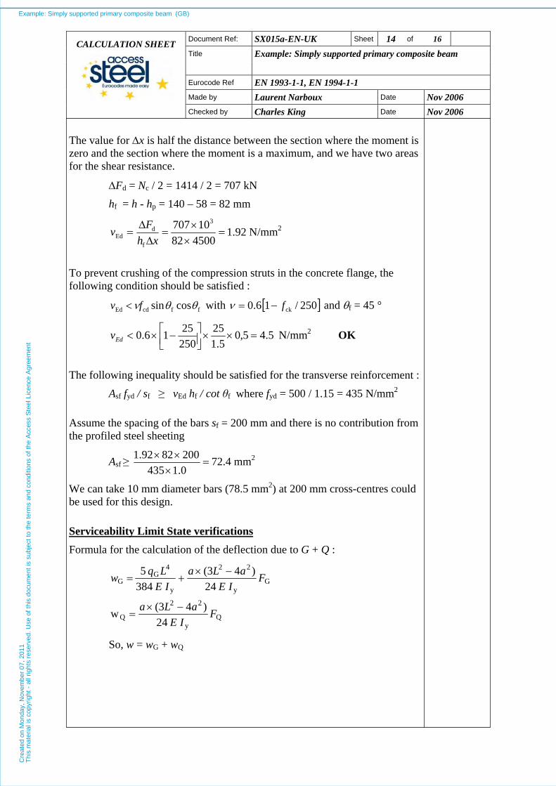
The value for Δx is half the distance between the section where the moment is zero and the section where the moment is a maximum, and we have two areas for the shear resistance.
ΔFd = Nc / 2 = 1414 / 2 = 707 kN
hf = h - hp = 140 – 58 = 82 mm
=×
×=
ΔΔ
=45008210707 3
f
dEd xh
Fv 1.92 N/mm2
To prevent crushing of the compression struts in the concrete flange, the following condition should be satisfied :
ffcdEd cossin θθνfv < with [ ]250/16.0 ckf−=ν and θf = 45 °
5.45,05.1
252502516.0 =××⎥⎦
⎤⎢⎣⎡ −×<Edv N/mm2 OK
The following inequality should be satisfied for the transverse reinforcement :
Asf fyd / sf ≥ vEd hf / cot θf where fyd = 500 / 1.15 = 435 N/mm2
Assume the spacing of the bars sf = 200 mm and there is no contribution from the profiled steel sheeting
Asf ≥ =×
××0.14352008292.1 72.4 mm2
We can take 10 mm diameter bars (78.5 mm2) at 200 mm cross-centres could be used for this design.
Serviceability Limit State verifications Formula for the calculation of the deflection due to G + Q :
Qy
22
Q
Gy
22
y
4G
G
24)4(3w
24)4(3
384 5
FIE
aLa
FIE
aLaIE
Lqw
−×=
−×+=
So, w = wG + wQ
Example: Simply supported primary composite beam (GB)C
reat
ed o
n M
onda
y, N
ovem
ber
07, 2
011
Thi
s m
ater
ial i
s co
pyrig
ht -
all
right
s re
serv
ed. U
se o
f thi
s do
cum
ent i
s su
bjec
t to
the
term
s an
d co
nditi
ons
of th
e A
cces
s S
teel
Lic
ence
Agr
eem
ent

Document Ref: SX015a-EN-UK Sheet 15 of 16 Title
Example: Simply supported primary composite beam
Eurocode Ref EN 1993-1-1, EN 1994-1-1 Made by Laurent Narboux Date Nov 2006
CALCULATION SHEET
Checked by Charles King Date Nov 2006
Construction stage
SLS Combination during the construction stage : FG = 49.0 kN
FQ = 13.5 kN
qG = 0.59 kN/m
EN 1990
§ 6.5.3
Deflection during the construction stage : Iy is the second moment of area of the steel beam.
49000101596221000024
)30004-90003(30001021596210000 384
900059.0 5 4
22
4
4
G ××××
×××+
×××××
=w
mm 4.290.284.1 G =+=w
mm 7.7135001021596210000 24
)30004-90003(3000w 4
22
Q =××××
×××=
So, w = wG + wQ = 29.4 + 7.7 = 37.1 mm
The deflection under (G+Q) is L/243
Final stage
SLS Combination
FG = 62.49 kN
FQ = 45.00 kN
qG = 0.59 kN/m
EN 1990
§ 6.5.3
Deflection at the final stage :
Iy depends on the modular ratio (n) depending on the type of loading. By simplification, we can take :
n0 = Ea / Ecm = 210000 / 31476 = 6.67 for short-term effects (Q)
So Iy = 77881 cm4 at mid span
And n = 3Ea / Ecm = 20.01 for permanent loads (G)
So Iy = 60297 cm4
EN 1994-1-1
§ 7.2.1
Example: Simply supported primary composite beam (GB)C
reat
ed o
n M
onda
y, N
ovem
ber
07, 2
011
Thi
s m
ater
ial i
s co
pyrig
ht -
all
right
s re
serv
ed. U
se o
f thi
s do
cum
ent i
s su
bjec
t to
the
term
s an
d co
nditi
ons
of th
e A
cces
s S
teel
Lic
ence
Agr
eem
ent
Document Ref: SX015a-EN-UK Sheet 16 of 16 Title
Example: Simply supported primary composite beam
Eurocode Ref EN 1993-1-1, EN 1994-1-1 Made by Laurent Narboux Date Nov 2006
CALCULATION SHEET
Checked by Charles King Date Nov 2006
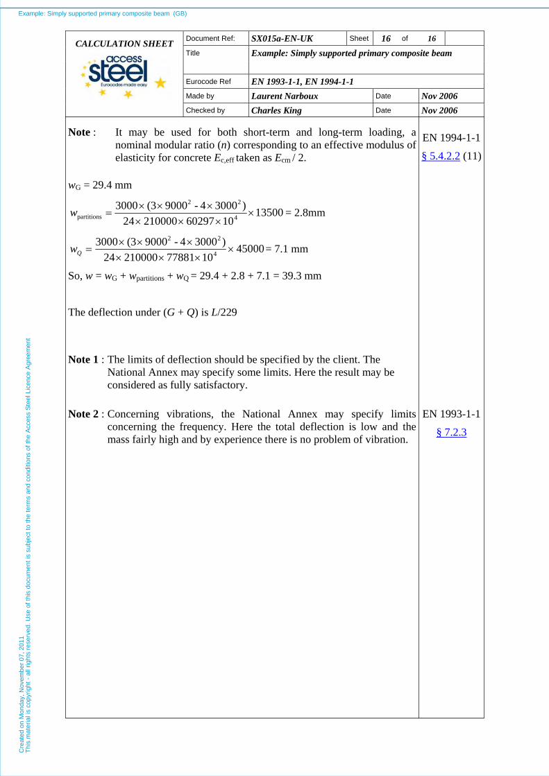
Note : It may be used for both short-term and long-term loading, a nominal modular ratio (n) corresponding to an effective modulus of elasticity for concrete Ec,eff taken as Ecm / 2.
EN 1994-1-1
§ 5.4.2.2 (11)
wG = 29.4 mm
135001060297210000 24
)30004-90003(30004
22
partitions ××××
×××=w = 2.8mm
450001077881210000 24
)30004-90003(30004
22
××××
×××=Qw = 7.1 mm
So, w = wG + wpartitions + wQ = 29.4 + 2.8 + 7.1 = 39.3 mm
The deflection under (G + Q) is L/229
Note 1 : The limits of deflection should be specified by the client. The National Annex may specify some limits. Here the result may be considered as fully satisfactory.
Note 2 : Concerning vibrations, the National Annex may specify limits concerning the frequency. Here the total deflection is low and the mass fairly high and by experience there is no problem of vibration.
EN 1993-1-1
§ 7.2.3
Example: Simply supported primary composite beam (GB)C
reat
ed o
n M
onda
y, N
ovem
ber
07, 2
011
Thi
s m
ater
ial i
s co
pyrig
ht -
all
right
s re
serv
ed. U
se o
f thi
s do
cum
ent i
s su
bjec
t to
the
term
s an
d co
nditi
ons
of th
e A
cces
s S
teel
Lic
ence
Agr
eem
ent
Example: Simply supported primary composite beam SX015a-EN-UK
Quality Record
RESOURCE TITLE Example: Simply supported primary composite beam
Reference SX015a-EN-GB
LOCALISED RESOURCE DOCUMENT
Name Company Date
Created by Laurent Narboux SCI Oct 2006
Technical content checked by Charles King SCI Oct 2006
Editorial content checked by D C Iles SCI 19/2/07
Example: Simply supported primary composite beam (GB)C
reat
ed o
n M
onda
y, N
ovem
ber
07, 2
011
Thi
s m
ater
ial i
s co
pyrig
ht -
all
right
s re
serv
ed. U
se o
f thi
s do
cum
ent i
s su
bjec
t to
the
term
s an
d co
nditi
ons
of th
e A
cces
s S
teel
Lic
ence
Agr
eem
ent