lbnf primary beam window and cartridge design review
TRANSCRIPT

LBNF Primary Beam Window and
Cartridge Design Review
Dave Pushka
LBNF Primary Beam Window and Cartridge Design Review
November 2020
Charge Questions:
1. Does the final design meet the requirements of the beamline components?
2. Does the window meet the FESHM safety requirements? Have all ESH and
Quality issues been identified and planned for?
3. Does the window meet the beam aperture requirements for both normal
operations and beam scans?
4. Does a viable plan exist for replacing the window in accordance with ALARA principles?
5. Are the interfaces identified and documented appropriately?
6. Is the final cost and schedule reasonable? Are procurements well planned?
7. Is the installation thought out and planned for? Potential problems identified?
8. Are the documents (requirements, specifications, schematics, engineering notes, procedures, and drawings) at the appropriate level for a final design?
12/15/2020Dave Pushka | LBNF Primary Beam Window and Cartridge Design Review2
Contents of Talk
• Primary Beam Window & Cartridge Overview
• Primary beam window thermal analysis and temperatures
– (As required by FESHM 5033.1)
• Cartridge Alignment Capabilities
• Charge Questions 1 to 8
12/15/2020Dave Pushka | LBNF Primary Beam Window and Cartridge Design Review3

Primary Beam Window
12/15/2020Dave Pushka | LBNF Primary Beam Window and Cartridge Design Review4
• Vacuum on the left hand side
• 3 psig on the right hand side
• Housing is 304 stainless steel
• Membrane is beryllium
• Fixed restraint
• Location for
cooling tubing
• Membrane inner diameter = 63.5 mm (~2.5 inches), outer diameter = 74.93 mm (2.95
inches)
• Hole thru housing is 63.5 mm (2.5 inches) in diameter
• Membrane thickness = 0.024 inches
(0.61 mm) Per FESHM 5033.1
• Designed for 18.7 psi delta P
Target Chase is pressurized at 4 psig max)
• See Fabrication Dwg in TC F10123128 (see
next slide).

12/15/2020Dave Pushka | LBNF Primary Beam Window and Cartridge Design Review5

12/15/2020Dave Pushka | LBNF Primary Beam Window and Cartridge Design Review6
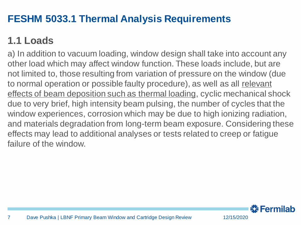
FESHM 5033.1 Thermal Analysis Requirements
1.1 Loads
a) In addition to vacuum loading, window design shall take into account any
other load which may affect window function. These loads include, but are
not limited to, those resulting from variation of pressure on the window (due
to normal operation or possible faulty procedure), as well as all relevant
effects of beam deposition such as thermal loading, cyclic mechanical shock
due to very brief, high intensity beam pulsing, the number of cycles that the
window experiences, corrosion which may be due to high ionizing radiation,
and materials degradation from long-term beam exposure. Considering these
effects may lead to additional analyses or tests related to creep or fatigue
failure of the window.
12/15/2020Dave Pushka | LBNF Primary Beam Window and Cartridge Design Review7
Thermal Analysis
• A series of thermal analyses were performed to evaluate the
effectiveness of cooling the perimeter of the window with
liquid cooling at two temperatures (35 C & 7 C) and the case
where the boundary condition at the liquid cooling interface
was perfectly insulated.
• Three different convective boundary conditions were set at
the surface of the window of 5, 25, and 250 W/m2-K to
evaluate the effect of the cooling from the target pile nitrogen
circulation system.
• Energy deposition in the window was provided by Diane
Reitzner on a per proton basis using MARS. Proton intensity
for 2.4 MW beam was used in the FEA.
12/15/2020Dave Pushka | LBNF Primary Beam Window and Cartridge Design Review8
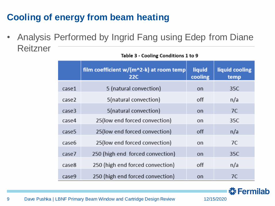
Cooling of energy from beam heating
• Analysis Performed by Ingrid Fang using Edep from Diane
Reitzner
12/15/2020Dave Pushka | LBNF Primary Beam Window and Cartridge Design Review9

Thermal Results at the Center of the Membrane:
12/15/2020Dave Pushka | LBNF Primary Beam Window and Cartridge Design Review10
beam on beam off Delta T Average
case1 95.1C 43.5C 51.6C 69.3C
case2 90.1C 38.4C 51.7C 64.25C
case3 68C 16.3C 51.7C 42.15C
case4 93.3C 41.6C 51.7C 67.45C
case5 87.2C 35.6C 51.6C 61.4C
case6 69C 17.4C 51.6C 43.2C
case7 83C 31.4C 51.6C 57.2C
case8 79.2C 27.5C 51.7C 53.35C
case9 74C 22.3C 51.7C 48.15C
Note there is no difference in Delta T in all cases. And that the liquid cooling at
35C should not be considered. The membrane temperature is reversed in
case 9 compared to Cases 3&6. This means the high end forced convection
should be avoided when liquid cooling is set at 7C. Furthermore, there is
almost no difference in temperature with natural convection or low end forced convection in Cases 3&6
Cooling, Key Results from Ingrid’s Analysis:
12/15/2020Dave Pushka | LBNF Primary Beam Window and Cartridge Design Review11
• The differences in temperature during the beam cycle remain constant in
all Cases 1 to 9.
• When the liquid cooling is absent, the membrane temperature is the
lowest with the high end forced convection in Case8.
• When the liquid cooling is applied at 7C, the membrane temperature is
almost the same under the natural convection or the low end forced
convection in Case3 and Case6.
• When the liquid cooling is applied at 7C, the high end forced convection
should be avoided since the membrane temperature is reversed in Case9.
• And all in all, the liquid cooling at 35C should not be considered in Case1,
Case2 and Case7.
• Note a peer review of Ingrid’s work was performed by Zhijing
Tang, a FEA and analysis expert in PPD.
Cooling – Conclusions:
• LCW is at about 35 C and should not be considered further as a cooling
alternative.
• Convection Coefficient for the N2 in the target Chase has not been
calculated as the CFD has not been performed.
– Will likely be in the 5 to 25 W/m^2-K range
• Case 5, (25 W/m2-K) convection, without liquid cooling provides a
temperature of about 87 C.
• Case 2 90 C with 5 W/m2-k convection (natural conv, no liquid cooling).
• Case 6, Liquid Cooling at 7 C (with low end forced convection) Only
Lowers the temperature by about 18 C ( lowers by 32 F) in the center of
the membrane.
• Adding Liquid cooling does not seem worth the effort (and cost to put in a
low temperature liquid cooling source).
• A CR to remove liquid cooling from the project scope has been initiated.
12/15/2020Dave Pushka | LBNF Primary Beam Window and Cartridge Design Review12

Corrosion considerations:
• One side of the window is exposed to beam line quality
vacuum while the other side is exposed to the nitrogen
atmosphere of the target chase.
• The choice to use nitrogen in the target chase (instead of air)
was made to reduce corrosion experienced at NuMI to all
components, including the primary beam window.
• Since corrosion issued for the NuMI window do not seem to
drive window lifetime, and the LBNF environment should be
more benign due to the nitrogen atmosphere, the FESHM
requirement to address corrosion issues has been met.
12/15/2020Dave Pushka | LBNF Primary Beam Window and Cartridge Design Review13

Cartridge:
• The cartridge is an assembly intended to fill the space around the hole
provided by CF between the PBE and the target chase.
• It allows the beam pipe (and the window attached to it) to be fine tuned to
be positioned to account for:
– Civil Construction location tolerances (Gross adjustments)
– Settlement of the building and enclosures over time (long term).
– Minor changes to the beam optics (long term).
• Gross adjustment (to address CF construction tolerances) are addressed
when the cartridge is installed in the hole. This allows transverse and
angular position adjustments.
• Typical long term adjustment range appropriate for this application is plus
or minus one inch (25 mm) in each direction (up-down, left-right).
• Rotations about the vertical axis and the horizontal axis (perpendicular to
the beam direction) are not required after the initial cartridge installation.
12/15/2020Dave Pushka | LBNF Primary Beam Window and Cartridge Design Review14
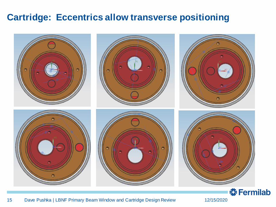
Cartridge: Eccentrics allow transverse positioning
12/15/2020Dave Pushka | LBNF Primary Beam Window and Cartridge Design Review15

Cartridge Made from Steel Tubes, Filled with Marble Fines
12/15/2020Dave Pushka | LBNF Primary Beam Window and Cartridge Design Review16

• Cartridge Grouted in Place post Beneficial
occupancy.
• Any angular alignment adjustments performed
before grouting
• Account for Civil Construction Tolerances
• Account for Settling
• Account for minor beam trajectory changes
• After Grouting, no additional angular adjustments
are easily performed.
• Transverse Adjustments on the order of Plus or
Minus 1 inch are always possible from the Pre-
target Side.
• These adjustments are made from the PBE end
where the radiation environment is less sever than
the target hall end.
Cartridge Installed in Pipe Sleeve Provided by CF
12/15/2020Dave Pushka | LBNF Primary Beam Window and Cartridge Design Review17

Q1: Does the final design meet the requirements of the
beamline components?
• Yes.
• Requirements for the
primary beam window
imaged from the
requirement are shown
to the left:
• The primary beam people (Phil Schlabach and Kevin Duel)
have seen and reviewed this design several times (most
recently September 8th 2020) and conclude it meets the
primary beam requirements, including the aperture needed for
beam scans.
12/15/2020Dave Pushka | LBNF Primary Beam Window and Cartridge Design Review18

Q2a: Does the window meet the FESHM safety
requirements?
• FESHM 5033.1 applies to thin
vacuum windows
• Key Engineering Note
Calculation shown at right:
– EN04530 in Teamcenter has
these calculations as required
by 5033.1
• Note Uniform pressure includes
additional pressure from N2 in
target chase.
• 5033.1 Required Thermal
analysis performed and
documented in DUNE docdb
20503
• This meets FESHM 5033.1
12/15/2020Dave Pushka | LBNF Primary Beam Window and Cartridge Design Review19

Q2b: Have all ESH and Quality issues been identified and
planned for?
• Building Primary beam vacuum
windows is well established.
– Window data base includes
approximately 76 windows
– All existing drawings studied as
part of this design effort.
• LBNF window process based on
NuMI / NOvA / ANU windows.
• QA plan includes CT scans of a
completed window
– This has become a standard practice.
– Included in cost and schedule
12/15/2020Dave Pushka | LBNF Primary Beam Window and Cartridge Design Review20
CT scan results for a titanium vacuum window brazed to a stainless steel conflat made by Omley Industries showing defects in the braze. Window size similar to the LBNF window.
Q3: Does the window meet the beam aperture requirements
for both normal operations and beam scans?
• Yes.
• Beam Scanning requirements are why this window is
physically larger than the NuMI / ANU window.
• In addition, provisions for a beryllium catcher screen were
added to the beam pipe following the discussion in
September
– Item 5 in assembly F10136776
– Not explicitly required by FESHM or other source.
12/15/2020Dave Pushka | LBNF Primary Beam Window and Cartridge Design Review21

Q4:Does a viable plan exist for replacing the window in
accordance with ALARA principles?
• LBNF window will be replaced using a plan very similar to
that used in MI-65.
• Beam pipe and window are extracted into the primary beam
enclosure and into a shielding cask, allowing worker to be in
a relatively benign environment.
• Design of the cask and cask transport equipment occurs later
in the project and are not included in this design review.
• LBNF cartridge installation will be similar to the sleeve
installation performed at NuMI circa 2003-2004.
• Installing the cartridge and primary beam window occurs in
approximately 4 to 5 years (2025) and the procedure for
these tasks are not included in this design review.
12/15/2020Dave Pushka | LBNF Primary Beam Window and Cartridge Design Review22

Q5: Are the interfaces identified and documented
appropriately??
• Interfaces to CF and
primary beam identified.
• F10128502 is the assembly
model file.
• Image on the right show the
interfaces between the
primary beam window
assembly and the primary
beam elements.
• Flange at end of
F10047628 is the agreed to
interface point.
12/15/2020Dave Pushka | LBNF Primary Beam Window and Cartridge Design Review23
Q6a: Is the final cost and schedule reasonable?
Q6b: Are procurements well planned?
12/15/2020Dave Pushka | LBNF Primary Beam Window and Cartridge Design Review24
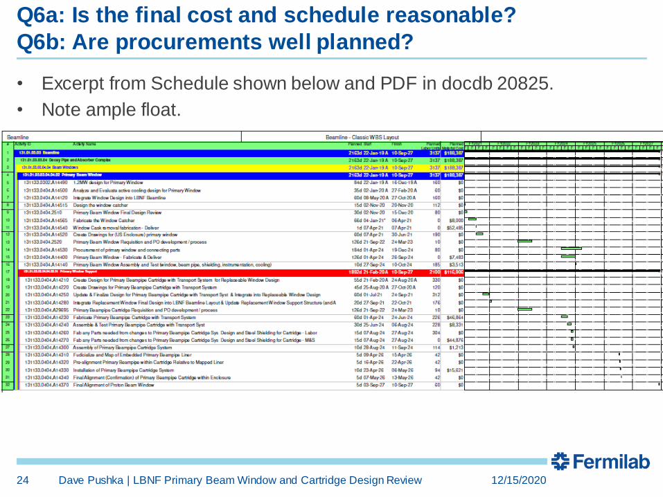
• Excerpt from Schedule shown below and PDF in docdb 20825.
• Note ample float.
Q7a: Is the installation thought out and planned for?
Q7b: Potential problems identified?
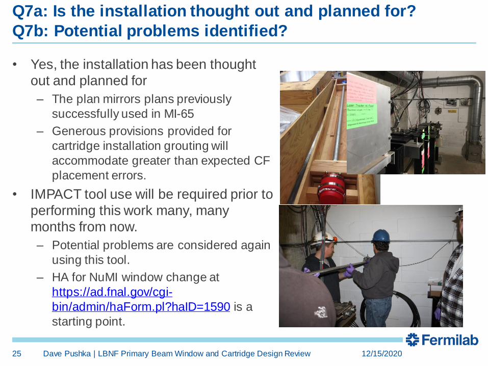
• Yes, the installation has been thought
out and planned for
– The plan mirrors plans previously
successfully used in MI-65
– Generous provisions provided for
cartridge installation grouting will
accommodate greater than expected CF
placement errors.
• IMPACT tool use will be required prior to
performing this work many, many
months from now.
– Potential problems are considered again
using this tool.
– HA for NuMI window change at
https://ad.fnal.gov/cgi-
bin/admin/haForm.pl?haID=1590 is a
starting point.
12/15/2020Dave Pushka | LBNF Primary Beam Window and Cartridge Design Review25

Q8: Are the documents (requirements, specifications, schematics, engineering
notes, procedures, and drawings) at the appropriate level for a final design?
• Drawing are released in TC
• Stand Alone Specifications are not needed (key specification
are embedded in the drawings & QA plan.)
12/15/2020Dave Pushka | LBNF Primary Beam Window and Cartridge Design Review26
The end
12/15/2020Dave Pushka | LBNF Primary Beam Window and Cartridge Design Review27
Back-up material on a Beryllium Catcher:
• A “beryllium catcher” is a second window, located on the beam line side of a
primary beam exit window, designed to limit the propagation of beryllium chards
into the beamline in the event of a failure of a beryllium window.
• There is no requirement for a beryllium catcher in FESHM.
• One was installed in NuMI because it was thought to be a good idea.
– A beryllium primary beam exit window failed in the MI abort when someone poked at it
with a tool.
– Very thin beryllium windows in a vacuum vessel in MTA were exposed to high differential
(well above the design) when the vessel was pressurized causing a titanium window to
fail. This is a very different situation from a primary beam exit window.
• A catcher window sees beam heating, but has little effective cooling (it is in a
vacuum).
• The NuMI catcher has openings around the perimeter to allow the downstream
vacuum to be evacuated.
• The LBNF design includes provision for a screen to serve as a catcher, while allowing more effective conductance for evacuation.
• The laboratory requirements for a catcher need to be better defined and the pros
and cons associated with a catcher need to be investigated and documented.
12/15/2020Dave Pushka | LBNF Primary Beam Window and Cartridge Design Review28