pressure monitoring system interfaced with global...
TRANSCRIPT
PRESSURE MONITORING SYSTEM INTERFACED WITH GLOBAL SYSTEM
FOR MOBILE COMMUNICATION (GSM)
KHALIL RUSHDI BIN ABDUL GHAFAR
B020910026
This Report Is Submitted In Partial Fulfillment of Requirements For The Bachelor
Degree of Electronic Engineering (Telecommunication Electronic)
Fakulti Kejuruteraan Elektronik dan Kejuruteraan Komputer
Universiti Teknikal Malaysia Melaka
June 2013
UNIVERSTI TEKNIKAL MALAYSIA MELAKAFAKULTI KEJI]RUTERAAN ELEKTRONIK DAN KEJURUTERAAN KOMPUTER
BORANG PENGESAIIAN STATUS LAPORAN
PROJEK SARJANA MT]DA II
Tajuk Projek
SesiPengajian
SeE==veE N-r+(taErt*LG' L'(nil"'-r#'-,\^'gy<tp-nt\ tF\
eqrrq "la+-lt-fu Eu-s.HS\ E.\N F.q\F.\\- €i{+f+e(HURUF BESAR)
mengaku membenarkan Laporan Projek Sarjana Muda ini disimpan di Perpustakaan dengan syarat-syarat kegunaan seperti berikut:
l. Laporan adalah hakmilik Universiti Teknikal Malaysia Melaka.
2. Perpustakaan dibenarkan membuat salinan untuk tujuan pengajian sahaja.
3. Perpustakaan dibenarkan membuat salinan laporan ini sebagai bahan pertukaran antara institusi
pengajian tinggi.
4. Silatandakan( { ),
tftfV
TERIIAD**
*(Mengandungi maklumat yang berdarjah keselamatan ataukepentingan Malaysia seperti yang termaklub di dalam AKTARAHSIA RASMI 1972)
**(Mengandungi maklumat terhad yang telah ditentukan olehorganisasi/badan di mana penyelidikan ddalankan)
TIDAKTERHAD
t ?* / \ 3
r*n , !.1 5- t-t € -:r=z \B rar*rr: ,i.1..il vr{r .
-s€ \3

111
DECLARATION
"I hereby, declare this report entitled "Pressure Monitoring System Interfaced with
GSM" is the result of my own research except as cited in references.
Signature
Name
Date
...........r......r..,,,.L.,..-r..\t..,. /;i.............
KHALIL RUSHDI BIN ABDUL GHAFAR
l1 JLIN 2013
IV
APPROVAL
This report is submitted to the Faculty of Electronic Engineering and Computer
Engineering (Electronic Telecommunication) of UTeM as a partial fulfilment of the
requirement for the degree 'of Bachelor of Electronic Engineering
(Telecommunication) (Hons.). The member of the supervisory committee is as
follow:
HuR F^I'Il:,:lt **'
'.urzsirfigff1;;iilyJ'rff.' ..'' . " " . ?6.r0'il1'iin'Ivr's' 91:'Yl'::''''
(Official Stamp of Supervisor)
NAME
DATE
PN. NUR FATIHAH BINTI AZ}iII
I IJUN 2013
iii
DEDICATION
Specially dedicate to
My beloved family, lecturers, supervisor and friends who have guided and inspired
me through my journey in education. Also thanks to their support, beliefs and
motivation.

iv
ACKNOWLEDGEMENT
Grace upon Allah S. W. T. because finally the project was done. Firstly, I
would like to thank my supervisor on “Pressure Monitoring System Interfaced with
GSM” project, Pn. Nur Fatihah Binti Azmi for guiding me for two semesters in order
to accomplish this project. Secondly, I would like to thank Engr. Siti Aisyah Binti
Anas as my temporarily supervisor. Although, she had been my supervisor for only a
month, I had learnt many things related to the project from her. Then, I want to thank
my parent as they keep on supporting me from the beginning. I also want to thank
my dearest friends who have been very helpful to me. And finally, thank you for
everyone who has been supporting me in finishing this project. I end this
acknowledgment with towards, thank you.

v
ABSTRACT
Pressure can be defined as a force presses over an area. It cannot be seen but
when it does you can feel it. Although pressure is sightless, it gives an impact to a
certain thing. One of a simple example that can explain the effect of pressure over an
area is s shaking tree blown by a wind. The wind presses over an area which is the
tree resulting in pressure. For some materials, pressure can change its properties.
These materials are chemical substances. An amount of force exerted by pressure can
change the nature and characteristics of the substances. For example, forces of
pressure can faster or slower the rate of reaction or melting point of a chemical
substance. The result is depended on a type of chemical being forced. In a chemical
processing industry, this factor might disturb the desired results which can cost a lot
of money to the company. Hence, in order to avoid this unwanted situation, a device
known as Pressure Monitoring System (PSM) interfaced with GSM is designed. The
device can detect force of pressure around by using pressure sensor and show it
based on a real time condition. The device also is implemented with warning system
in order to notify people about the current pressure condition. The warning system
consists light indicator and message notification.
vi
ABSTRAK
Tekanan boleh didefinisikan sebagai daya yang dikenakan ke atas suatu
kawasan. Tekanan adalah sesuatu yang tidak dapat dilihat tetapi ianya boleh dirasai.
Walaupun tekanan tidak dapat dilihat, tetapi ia dapat memberi kesan kepada
sesetengah benda. Suatu contoh mudah untuk menerangkan tekanan ialah pokok
yang bergoncang semasa ditiup angin. Angin yang bertiup menekan pokok tersebut
yang mana adalah salah satu konsep tekanan. Untuk sesetengah bahan, tekanan dapat
merubah sifat-sifatnya. Bahan yang dimaksudkan tersebut adalah bahan kimia.
Tekanan yang dikenakan keatas bahan-bahan kimia boleh merubah bentuk dan sifat-
sifatnya. Sebagai contoh, tekanan dapat mempercepatkan atau memperlahankan
kadar reaksi dan takat lebur sesuatu bahan kimia tersebut. Kadar reaksi dan takat
lebur tersebut bergantung kepada jenis bahan kimia yang terbabit. Dalam industry
pemprosesan kimia, benda-benda ini boleh menjejaskan hasil yang dijangka dan
seterusnya mendatangkan kerugian kepada syarikat. Jadi, untuk mengelakkan
daripada terjadi keadaan begitu, suatu alat yang dikenali sebagai “Pressure
Monitoring System” (PMS) yang digabung dengan GSM direka. Alat tersebut boleh
megesan tekanan udara di sekeliling menggunakan pengesan tekana dan menyiarkan
bacaan tersebut secara langsung. Alat tersebut juga dibekalkan dengan sistem amaran
untuk memberi amaran tentang keadaan tekanan semasa. Sistem amaran terdiri
daripada penunjuk cahaya dan pemberitahuan melalui mesej.
vii
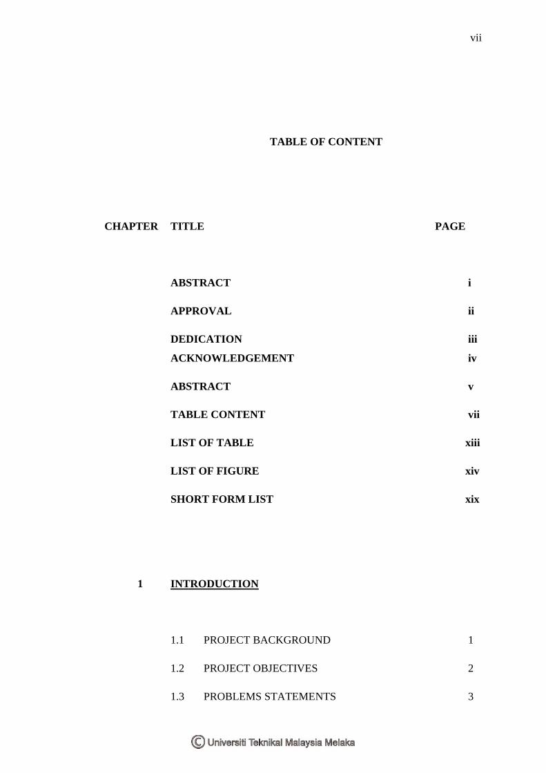
TABLE OF CONTENT
CHAPTER TITLE PAGE
ABSTRACT i
APPROVAL ii
DEDICATION iii
ACKNOWLEDGEMENT iv
ABSTRACT v
TABLE CONTENT vii
LIST OF TABLE xiii
LIST OF FIGURE xiv
SHORT FORM LIST xix
1 INTRODUCTION
1.1 PROJECT BACKGROUND 1
1.2 PROJECT OBJECTIVES 2
1.3 PROBLEMS STATEMENTS 3

viii
1.4 PROJECT SCOPE 5
1.5 PROJECT METHODOLOGY 6
2 LITERATURE REVIEW
2.1 INTRODUCTION 8
2.2 PRESSURE SENSOR 9
2.3.1 PRESSURE OVERVIEW 9
2.3.2 TYPES OF PRESSURE MEASUREMENTS 10
2.3.3 PRESSURE SENSING TECHNOLOGY 11
2.4 MICROCONTROLLER 19
2.4.1 POCESSOR OR CONTROL PROCESSING 20
UNIT
2.4.2 MEMORY 20
2.4.3 INPUT AND OUTPUT 21
2.4.4 MICROCONTROLLER WORKING 22
OVERVIEW
2.4.5 PIC 16F877 ARCHITECTURE 23
2.5 GLOBAL SYSTEM FOR MOBILE 24
COMMUNICATION (GSM)
2.5.1 MAX 232 25
2.6 LIQUID CRYSTAL DISPLAY (LCD) 26

ix
2.7 EFFECT OF PRESSURE ON MELTING POINT 27
2.7.1 EFFECT OF PRESSURE 27
2.7.2 ESTIMATING THE EFFECT OF PRESSURE 28
2.7.3 THE SIMON EQUATION 30
2.8 DOWNHOLE PRESSURE AND TEMPERATURE 31
GAUGE DESIGN
2.8.1 ABSTRACT 31
2.8.2 INTRODUCTION 32
2.8.3 TECHNOLOGY SPECIFICATION 32
REQUIREMENT
2.8.4 HARDWARE OVERALL SCHEME 32
2.8.5 HARDWARE ARCHITECTURE 34
2.8.6 USB COMMUNICATION MODULE 34
2.8.7 SOFTWARE DESIGN 35
2.8.8 CONCLUSION 37
2.9 MEASURING WATER LEVEL WITH THE 37
PRESSURE SENSOR AND MICROCONTROLLER
PIC 16F877A
2.9.1 ABSTRACT 37
2.9.2 INTRODUCTION 38
2.9.3 SYSTEM DEVELOPMENT 38
2.9.4 DESCRIPTION PRESSURE 39
SENSOR MPX
2.9.5 CONDITIONING AND AMPLIFICATION 40

x
2.9.6 UNIT DIGITAL SIGNAL PROCESSING 41
2.9.7 LEVEL MEASUREMENT METHODOLOGY 42
2.9.8 RESULT AND DISCUSSION 43
2.9.9 CONCLUSION 43
2.10 DESIGN OF MODULAR PRESSURE 44
TRANSMITTER WITH WIRELESS
CAPABILITY
2.10.1 ABSTRACT 44
` 2.10.2 INTRODUCTION 44
2.10.3 TRANSMITTER DESIGN 45
2.10.4 PROTOTYPE DEVELOPMENT 47
AND TESTING
2.10.5 CONCLUSION 49
2.11 IMPLEMENTATION OF TIRE PRESSURE 50
MONITORING SYSTEM WITH WIRELESS
COMMUNICATION
2.11.1 INTRODUCTION 50
2.11.2 OPERATION OF THE SYSTEM 51
2.11.3 HARDWARE DESCRIPTION 54
2.11.4 CONCLUSION AND FUTURE WORK 56
3 POJECT METHODOLOGY

xi
3.1 INTRODUCTION 57
3.2 PROJECT PLANNING 58
3.2.1 PROJECT PLANNING FLOW CHART 59
3.3 BLOCK DIAGRAM 61
3.4 SYSTEM MECHANISM 63
3.6 PROTOTYPE DESIGN 65
4 RESULT AND DISCUSSION
4.1 I NTRODUCTION 67
4.2 CIRCUIT DESIGN 68
4.2.1 POWER SUPPLY 70
4.2.2 PRESSURE SENSOR MPX5700 AND ITS 70
CALIBRATION
4.2.3 MICROCONTROLLER PIC 16F877A 74
4.2.4 LIQUID CRYSTAL DISPLAY 76
4.2.5 LIGHT-EMITTING DIODE (LED) 77
4.2.6 GLOBAL SYSTEM FOR MOBILE 79
COMMUNICATION (GSM) AND MAX 232
4.3 SOFTWARE DESIGN 81
4.3.1 ANALOG-TO-DIGITAL (ADC) MODULE 82
4.3.2 LCD AND LEDS AS OUTPUT 84
4.3.3 GSM 87
xii
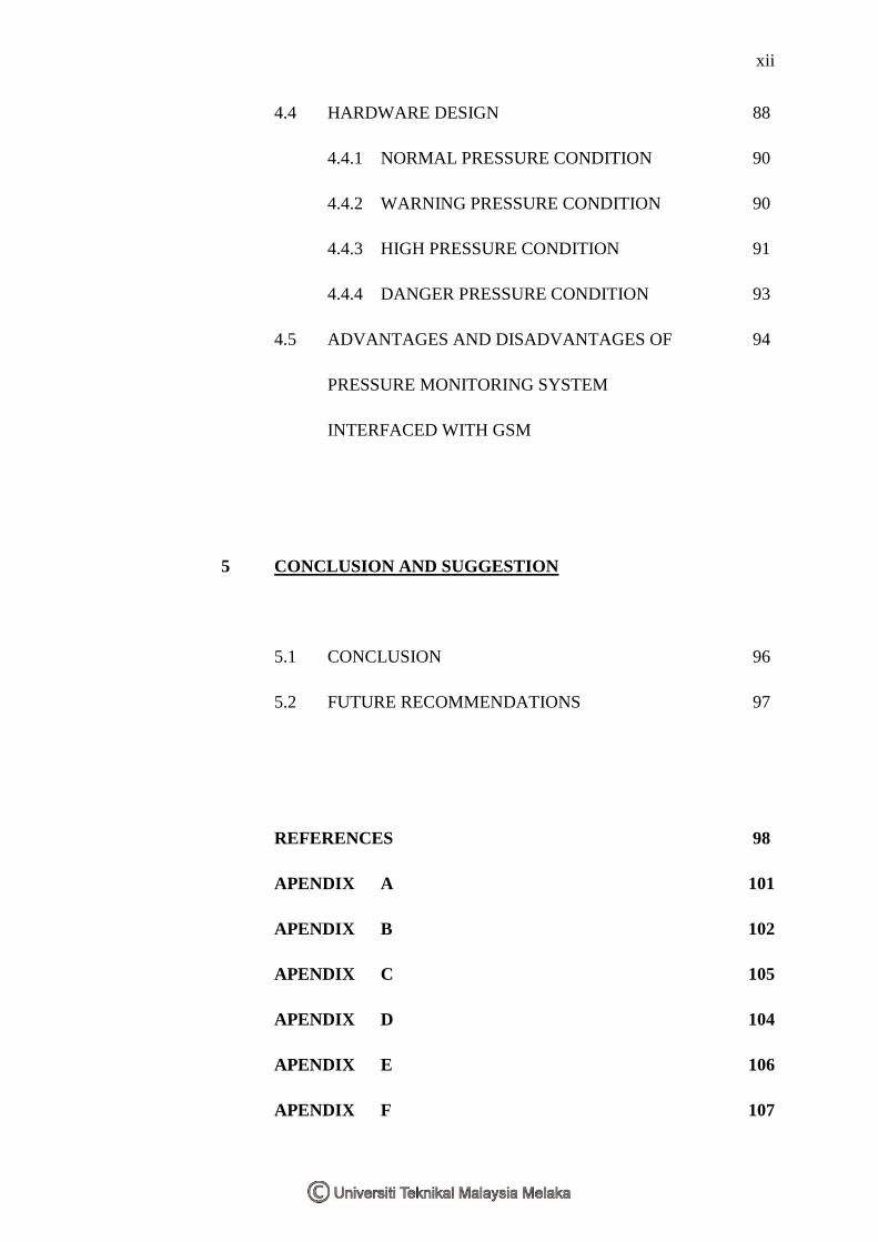
4.4 HARDWARE DESIGN 88
4.4.1 NORMAL PRESSURE CONDITION 90
4.4.2 WARNING PRESSURE CONDITION 90
4.4.3 HIGH PRESSURE CONDITION 91
4.4.4 DANGER PRESSURE CONDITION 93
4.5 ADVANTAGES AND DISADVANTAGES OF 94
PRESSURE MONITORING SYSTEM
INTERFACED WITH GSM
5 CONCLUSION AND SUGGESTION
5.1 CONCLUSION 96
5.2 FUTURE RECOMMENDATIONS 97
REFERENCES 98
APENDIX A 101
APENDIX B 102
APENDIX C 105
APENDIX D 104
APENDIX E 106
APENDIX F 107
xiii
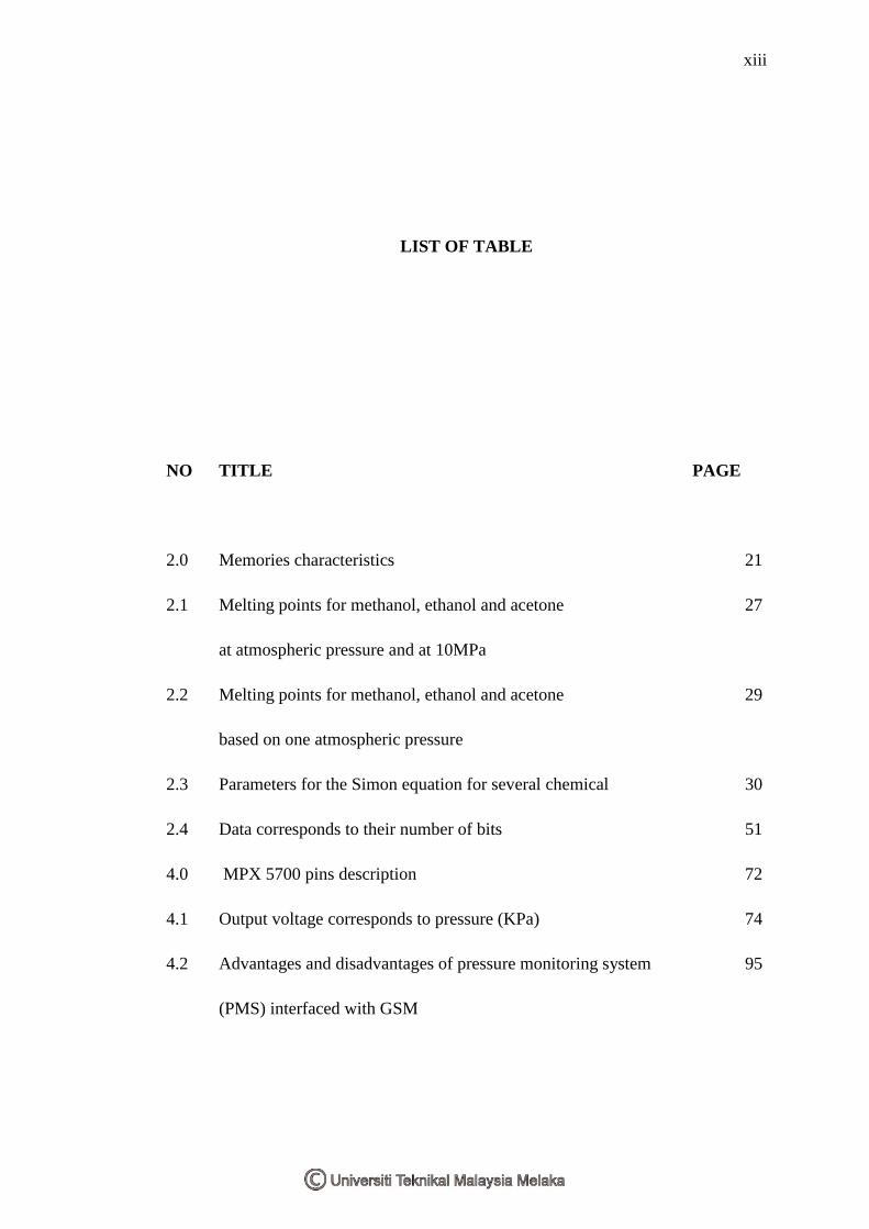
LIST OF TABLE
NO TITLE PAGE
2.0 Memories characteristics 21
2.1 Melting points for methanol, ethanol and acetone 27
at atmospheric pressure and at 10MPa
2.2 Melting points for methanol, ethanol and acetone 29
based on one atmospheric pressure
2.3 Parameters for the Simon equation for several chemical 30
2.4 Data corresponds to their number of bits 51
4.0 MPX 5700 pins description 72
4.1 Output voltage corresponds to pressure (KPa) 74
4.2 Advantages and disadvantages of pressure monitoring system 95
(PMS) interfaced with GSM

xiv
LIST OF FIGURE
NO TITLE PAGE
1.0 Effect of pressure on chemicals melting point 4
1.1 Particles in chemical as exerted by pressure 4
1.2 Pressure monitoring system interfaced with GSM flow chart 7
2.0 The piezoresistive material under normal state (left) and when 11
exerted by the pressure force
2.1 Longitudinal gauge factor (a) and transverse 13
gauge factor (b) and (c)
2.2 Wheatstone bridge in the sensor (a) and Wheatstone 14
bridge circuit (b)
2.3 Piezoelectric sensor connects with charged amplifier 16
2.4 Touch mode capacitive pressure sensor 17
2.5 Sensor’s force collector deforms when exerting by a pressure 18
2.6 Capacitance is linear with the pressure applied 19
2.7 Process of fetching the instruction in microcontroller 20

xv
2.8 Parallel and serial data transferred 22
2.9 PIC 16F877 architecture 23
2.10 GSM modem 24
2.11 MAX 232 IC 25
2.12 2 x 16 LCD 26
2.13 Melting point for methanol, ethanol and acetone 27
based on exerted pressure
2.14 “Pressure Independent” Clapeyron Equation Estimates 29
and Data for Methanol
2.15 Comparison of the Simon Equation estimates to 31
experimental data
2.16 Pressure gauge system block diagram 34
2.17 Pressure gauge software flow chart 35
2.18 Result of pressure and temperature display on PC 36
2.19 System block diagram 38
2.20 MPX2010GS block diagram 39
2,21 Circuit for signal conditioning unit 40
2.22 Water level based on pressure sensor circuit 41
designed in proteus software
2.23 Water level system based on pressure sensor 42
circuit on strip board
2.24 Detection of water level based on pressure mechanism 42
2.25 Relationship between detected pressures with water level 43

xvi
2.26 Pressure gauge system block diagram 45
2.27 Circuit designed in proteus software 47
2.28 Circuit for transmitter module built on breed board 48
2.29 Result generated at 30mV 48
2.30 Result generated at 60mV 49
2.31 First two bits number indicate the type of data 52
2.32 Transmitting unit flow chart 52
2.33 Receiving unit flow chart 54
2.34 Special nozzle used to connect stem valve with the sensor 54
2.35 Special nozzle 55
3.0 Project planning flow chart 60
3.1 PMS interfaced with GSM block diagram 62
3.2 Output processing 63
3.3 Pressure monitoring system interfaced with GSM flow chart 64
3.4 Pressure vessel to measure pressure 66
3.5 Sensor attached inside the bottle 67
4.0 Proteus software 69
4.1 Pressure monitoring system interfaced with GSM block diagram 69
4.2 Pressure monitoring system interfaced with GSM circuit 70
4.3 PCB layout 70
4.4 Power supply circuit 71
4.5 MPX5700 pressure sensor 71
4.6 Graph of pressure (KPa) versus sensor output (V) 73

xvii
4.7 Block diagram for MPX5700 75
4.8 PIC 16F877A 75
4.9 Basic PIC 16F877A circuit diagram 76
4.10 Liquid Crystal Display (LCD) 2 x 16 77
4.11 LCD circuit 78
4.12 Red LEDs 78
4.13 LEDs circuit 79
4.14 Warning pressure level 80
4.15 High pressure level 80
4.16 Danger pressure level 80
4.17 MAX 232 circuit 81
4.18 D-sub 9 connection 82
4.19 GSM modem 82
4.20 CCS C Compiler 83
4.21 ADC initialization 84
4.22 ADC coding 85
4.23 LCD driver 85
4.24 Initializing LCD 86
4.25 LCD’s coding 86
4.26 First level detection coding 86
4.27 Second level output coding 87
4.28 Third level output coding 87
4.29 Final level output coding 87

xviii
4.30 GSM coding 88
4.31 Initializing USART module for GSM interfaced 88
4.31 Coding for level three condition (LED + LCD + GSM) 88
4.32 A complete pressure monitoring system interfaced with GSM circuit 89
prototype
4.33 Copper printed on PCB board 90
4.33 Pressure monitoring system interfaced with GSM prototype 90
4.34 LCD result under normal pressure condition 91
4.35 LCD result under warning pressure condition 91
4.36 Green LED output is high under warning condition 92
4.37 Message sent by GSM under warning condition 92
4.38 LCD result under high pressure condition 93
4.39 Red LED output is high under warning condition 93
4.40 Message sent by GSM under warning condition 93
4.41 LCD result under danger pressure condition 94
4.42 Both LED outputs are high under danger condition 94
4.43 Message sent by GSM under warning condition 94
xix
SHORT FORM LIST
PMS - Pressure Monitoring System
TPMS - Tire Pressure Monitoring System
LCD - Liquid Crystal Display
GSM - Global System for Mobile Communication
PSI - Pounce per Square Inch
Pa - Pascal
K - Kilo
M - Mega
Hz - Hertz
ID - Identification
Kmph - Kilo Meter per Hour
MCU - Microcontroller Unit
RAM - Random Access Memory
DSP - Digital Signal Processing
PVDF - Polyvinylidene Fluoride

xx
RFID - Radio Frequency Identification
CPU - Center Processing Unit
I/O - Input/Output
ROM - Read Only Memory
USB - Universal Serial Bus
RF - Radio Frequency
AM - Amplitude Modulation
FM - Frequency Modulation
ASK - Amplitude Shift Keying
FSK - Frequency Shift Keying
MODEM - Modulation and Demodulation
SIM - Subscriber Identity Module
FDMA - Frequency Division Multiple Access
TDMA - Time Division Multiple Access
IMSI - International Mobile Subscriber Identity
SMS - Short Message Service
CRT - Cathode Ray Tube
IC - Integrated Circuit
ASIC - Application Specified Integrated Circuit
ADC - Analog to Digital Converter
CMOS - Complementary metal–oxide–semiconductor
LIN - Local Interconnect Network
TTL - Transistor-transistor logic
xxi
GPS - Global Positioning System
ISM - Industrial, Scientific and Medical
SPI - Serial Peripheral Interface
MOSI - Master Out Slave In
MISO - Master In Slave Out
EEPROM - Erasable Programmable Read-Only Memory
UART - Universal Asynchronous Receiver/Transmitter
USART - Universal Synchronous/Asynchronous Receiver/Transmitter
PIC - Programmable Integrated Chip
IC - Integrated Circuit
LED - Light-Emitting Diode
PCB - Printed Circuit Layout
TX - Transmitter
RX - Receiver
STD - Subscriber Trunk Dialing
BTS - Base Transceiver Station
BSC - Base Station Controller
USB - Universal Serial Bus
PC - Personal Computer
IIC - Inter-Integrated Circuit
PVC - Polyvinyl-chloride
MEMS - Micro-electromechanical system
xxii
LIST OF APPENDICES
NO TITLE PAGE
A MPX 5700 Operating characteristics 101
B MPX 5700 Circuit connection 102
C MPX 5700 Package dimension 103
D MPX 5700 Pins style 104
E PIC 16F877A I/O pins 105
F PIC 16F877A Adcon1 register 106