high penetration of power electronic interfaced power
TRANSCRIPT

High Penetration of Power Electronic Interfaced Power Sources and the Potential Contribution of Grid Forming ConvertersTechnical Report
European Network ofTransmission System Operators
for Electricity
ENTSO-E Technical Group on High Penetration of Power Electronic Interfaced Power Sources

The current report is supported by the following organisations: ENTSO-E, the European Network of Transmission System Operators for electricity, represents 43 electricity transmission system operators (TSOs) from 36 countries across Europe. ENTSO-E was established and given legal mandates by the EU’s Third Legislative Package for the Internal Energy Market in 2009, which aims to further liberalise the gas and electricity markets in the EU.
Avenue de Cortenbergh 100, 1000 Brussels, Belgium T +32 2 741 09 50 www.entsoe.eu WindEurope is the voice of the wind industry, actively promoting wind power in Europe and worldwide. It has over 400 members with headquarters in more than 35 countries, including the leading wind turbine manufacturers, component suppliers, research institutes, national wind energy associations, developers, contractors, electricity providers, financial institutions, insurance companies and consultants. This combined strength makes WindEurope Europe’s largest and most powerful wind energy network.
Rue Belliard 40, 1040 Brussels, Belgium
T +32 2 213 1811 www.windeurope.org
SolarPower Europe is the trade association representing the solar industry. It has over 200 members over the entire photovoltaic value chain. The aim of SolarPower Europe is to make solar the core of a smart, sustainable, secure and inclusive energy system in order to reach carbon neutrality before 2050.
Rue d’Arlon 69-71, 1040 Brussels, Belgium T +32 2 709 55 20 www.solarpowereurope.org
T&D EUROPE is the European association of the electricity transmission and distribution equipment and services industry. It covers the complete range of products and services necessary to transport and distribute electricity in high and medium voltage. T&D Europe is working towards future-proofing the electricity networks in Europe by means of policy, technology and investments.
BluePoint Building, Boulevard A Reyers 80, 1030 Brussels, Belgium T +32 2 206 68 67 www.tdeurope.eu

Technical Report ‘High Penetration of Power Electronic Interfaced Power Sources and the Potential Contribution of Grid forming Converters’ Page 1
Technical Report
High Penetration of Power Electronic Interfaced Power Sources and the Potential Contribution of Grid Forming Converters
ENTSO-E Technical Group on High Penetration of Power Electronic Interfaced Power Sources

Technical Report ‘High Penetration of Power Electronic Interfaced Power Sources and the Potential Contribution of Grid forming Converters’ Page 2
Members of the ENTSO-E Technical Group on High Penetration of Power Electronic Interfaced
Power Sources:
WindEurope members/representatives:
• Peter Christensen, Vestas, Denmark / later Gert Karmisholt Andersen
• Matthias Seidel, Senvion, Germany / later Sigrid Bolik
• Sönke Engelken, Enercon, Germany
• Thyge Knueppel, Siemens WP, UK
T&D Europe members/representatives:
• Athanasios Krontiris, ABB, Germany
• Klaus Wuerflinger, Siemens, Germany
SolarPower Europe members/representatives:
• Thorsten Bülo, SMA, Germany
ENTSO-E members/representatives:
• Jörg Jahn, TenneT TSO, Germany / later Mario Ndreko,
• Saeed Salehi, 50Hertz Transmission, Germany
• Ioannis Theologitis, ENTSO-E
Power System Analysis tool Providers/Consultants:
• Bernd Weise, DIgSILENT, Germany
• Helge Urdal, Urdal Power Solutions, UK
Academia:
• Agusti Egea, University of Strathclyde, UK / earlier Andrew J Roscoe
• Jens Fortmann, HTW Berlin, Germany

Technical Report ‘High Penetration of Power Electronic Interfaced Power Sources and the Potential Contribution of Grid forming Converters’ Page 3
Contents Executive Summary ................................................................................................................................. 5
Abbreviations ........................................................................................................................................ 11
1 The Interconnected European Power System: Power System Stability Challenges with High levels
of Power Electronic Based Sources ....................................................................................................... 13
1.1 Moving towards high penetration of power electronic interfaced generation .................... 13
1.2 Power system stability challenges ......................................................................................... 14
1.2.1 The reduction of total system inertia ............................................................................ 14
1.2.2 System split.................................................................................................................... 17
1.2.3 Short-circuit power levels .............................................................................................. 18
1.2.4 Rotor angle stability....................................................................................................... 19
1.2.5 Voltage stability ............................................................................................................. 19
1.2.6 Other instabilities relating to fast dynamics of power converters ................................ 19
2 Power System Needs under High Penetration of PEIPSs: The need for Grid Forming Converters 20
2.1 Classes of Power Electronic Interfaced Power Sources arising from IGD HPoPEIPS ............. 20
2.1.1 Class 1 Power Park Modules .......................................................................................... 20
2.1.2 Class 2 PPM / HCS .......................................................................................................... 20
2.1.3 Class 3 PPM / HCS .......................................................................................................... 21
2.2 Requirements for Grid Forming Power Electronic Interfaced Power Sources ...................... 21
2.2.1 Create system voltage ................................................................................................... 22
2.2.2 Contribute to fault level / fault current contribution .................................................... 23
2.2.3 Sink for harmonics ......................................................................................................... 24
2.2.4 Sink for unbalances ....................................................................................................... 25
2.2.5 Contribution to inertia ................................................................................................... 25
2.2.6 System survival to allow effective operation of LFDD (Load Frequency Demand
Disconnection) ............................................................................................................................... 27
2.2.7 Prevent adverse control interaction ............................................................................. 28
2.3 Operational boundaries for GFC performance ...................................................................... 33
2.3.1 Example: inertial response ............................................................................................ 35
2.4 Cost Considerations ............................................................................................................... 35
2.4.1 Considerations for wind power plants .......................................................................... 37
2.4.2 Considerations for PV plants ......................................................................................... 37
2.4.3 Considerations for Grid Scale High Power Storage (lithium ion or comparable
technology) .................................................................................................................................... 38
2.4.4 Considerations for HVDC installations .......................................................................... 38
2.5 Must-Run Units ...................................................................................................................... 39
2.6 Synchronous Compensators / Condensers ........................................................................... 40

Technical Report ‘High Penetration of Power Electronic Interfaced Power Sources and the Potential Contribution of Grid forming Converters’ Page 4
2.7 Spatial Distribution of Grid Forming Units or Must-Run Units .............................................. 40
3 Proposed Tests and Benchmarking ............................................................................................... 41
3.1.1 Control and subsystem testing ...................................................................................... 42
3.1.2 Site testing ..................................................................................................................... 43
4 Outstanding questions .................................................................................................................. 44
5 Bibliography ................................................................................................................................... 47
6 Annex ............................................................................................................................................. 53
6.1 Terminology and Definitions ................................................................................................. 53
6.2 Characterising of Converter Based Inertial Response for Generic Performance Evaluation of
Gain and Damping Factors ................................................................................................................ 57

Technical Report ‘High Penetration of Power Electronic Interfaced Power Sources and the Potential Contribution of Grid forming Converters’ Page 5
Executive Summary
Europe, in common with substantial parts of the world [1], [2], [3] is increasingly moving towards
generating electricity from Renewable Energy Sources (RES) [4], which are predominantly connected
to the power system via power electronic converters. In addition, power electronic interfaces are
added on the demand side (smart loads, motor drive systems and electrical chargers for Electric
Vehicles [EVs]) and also at the transmission level (e.g. bulk High Voltage Direct Current [HVDC] as
well as offshore HVDC links) [5].
At times of high RES generation delivered at low marginal cost (due to no fuel cost), conventional
thermal generation uses large Synchronous Generators (SGs) that are ‘out of merit’ and are therefore
potentially disconnected. Periods in which RES have the potential to supply all, or close to all the
system demand are increasing and becoming a reality for an increasing number of countries. Figure 2
represents a scenario for 2025 in this respect. Ireland is one extreme European example, where
constraining/substituting wind above 65% of demand is already being experienced with installed
wind capacity of 4 GW, and yet another 10 GW of new wind capacity is expected by 2030 [6]. Such a
high uptake of RES is linked to dramatic reductions in installation costs of new wind and solar
Photovoltaic (PV), making these sources increasingly competitive with thermal energy [1].
In parallel, the power systems in several European countries are undergoing structural changes,
whereby business as usual is being challenged, most notably by larger and more volatile power flows
over greater distances [4], [5], [7].
This report collates analysis since the end of 2016 by a group of experts from across the power
industry called Technical Group High Penetration (TG HP), focused on the power electronic
converters that are being used as an interface towards the Alternating Current (AC) power system in
a wide range of applications covering power generation, transmission and consumption/demand,
and which have the effect of changing the dynamic properties of the AC power system. The analysis
is concentrated on one of the potential solutions for the extreme case of Power Electronic Interfaced
Power Sources (PEIPS) contributing between 60 and 100% of the total instantaneous power supply. It
defines the characteristics of one emerging solution, that of applying Grid Forming Converters (GFC).
It does not address adequacy issues of low RES generation compared to demand. The TG HP has
been reporting the developments via ENTSO-E to the Grid Connection European Stakeholder
Committee (GC ESC), reflecting its initiation.
Extensive research on the topic of this report is being undertaken elsewhere, including the European
R&D project MIGRATE which is currently releasing its reports [8], [9], [10], [11], [12], [13]. Several
national and international organisations (worldwide) are engaged in current activity on this topic [6],
[14], [15], [16], [17], [18], [19], [20], [21], [22] [23], [24], [25], [26], [27], [28], [29], [30]. This report
concentrates on the potential contribution of GFC to the secure operation of the power system
where its generation is dominated by PEIPS. The report does not claim to provide extensive cover of
alternatives means to GFC to deliver the capabilities identified, although it does introduce the reader
to one of them, the use of synchronous condensers, including the possible addition of flywheels.
Previous work developing Connection Network Codes (CNCs) has defined system needs and how to
successfully satisfy such needs for lower PEIPS penetration, approximately up to 60% in a
Synchronous Area (SA), as expressed in these CNCs at European level and at national level in Grid
Codes or equivalent documents. However, in the operating range of PEIPS of 60 to 100% of the total
demand at the time, fewer or no SGs (in the case of 100%) are connected based on economical ‘in
merit’ energy market reasons.

Technical Report ‘High Penetration of Power Electronic Interfaced Power Sources and the Potential Contribution of Grid forming Converters’ Page 6
The traditional electrical power system and electricity markets have been designed to work with SGs,
and so these have traditionally provided various ‘inherent’ capabilities to the system critical to
ensure the stable operation of the power systems during severe faults and even basic system survival
during rare system splits. Due to the potential total absence of SGs approaches during periods of high
penetration (HP) of PEIPS infeed, the wider industry has engaged in a closer examination of the lack
of these system capabilities [4], [17], [31], [32]. Traditionally, the focus in the context of PEIPS has
been on steady state and a limited number of dynamic (faster) aspects recently expanded to include
PEIPS contributing fast fault current during system faults and extended contribution to frequency
management (although this latter capability has been required from RES for more than 10 years in
some countries). Demand side contributions in these contexts are emerging and have significant
potential.
However, the analysis of situations of High Penetration of Power Electronics Power Sources
(HPoPEIPS) [33] has identified further System Operator (SO) concerns, including the low or
potentially inadequate supply of:
• Total System Inertia (TSI)
• Fault Current Infeed described as Fault Level (FL) and also affecting Short Circuit Ratio (SCR)
The combination of the above two elements is summarised by the term low system strength. The
seven topics of concern in this context examined by TG HP are:
• Creating system voltage
• Contributing to fault level
• Sink for harmonics
• Sink for unbalance
• Contribution to inertia
• System survival to allow effective operation of Low Frequency Demand Disconnection (LFDD)
• Preventing adverse control interactions
These critical capabilities or behavioural characteristics must continue to be adequately delivered,
even when operating close to a 100% penetration of converter interfaced power sources, in order to
continue to ensure stable voltage, frequency and system angle under all operating conditions (steady
state and disturbed).
Each of the above aspects could be treated in isolation, or alternatively solutions to these challenges
could be sought in an integrated or holistic manner. In the view of some Transmission System
Operators (TSOs), there is a risk associated with treating the challenges individually, as a positive
contribution to one aspect may be detrimental to another. An example of this is that a pure form of
contribution to synthetic inertia may be detrimental to control interactions by making these worse
rather than better, and has therefore not been adopted (See [33] with associated further references).
Although analysis of the power system characteristics and needs should be done in a holistic manner,
some of the critical capabilities indicated above could be provided in a shared manner, e.g. while
some converters create system voltage and contribute to fault level in the positive sequence, other
converters in the power system could serve as sinks for unbalance. The value of a holistic approach
versus shared delivery has not been fully analysed by this group.
To cover the above outline system needs, the TG HP classifies existing and future power park
modules (PPMs) into Classes 1, 2 and 3, with Classes 1 and 2 reflecting respectively basic (early) and
advanced (recent) capabilities of existing units. Section 2.1.3 defines the high level characteristics of
a future Class 3 of PPMs and HVDC converter systems (HCS) [33] as follows:

Technical Report ‘High Penetration of Power Electronic Interfaced Power Sources and the Potential Contribution of Grid forming Converters’ Page 7
‘Class 3 PPMs or HCSs shall be capable of supporting the operation of the ac power system (from EHV
to LV) under normal, alerted, emergency, blackout and restoration states without having to rely on
services from synchronous generators. This shall include the capabilities for stable operation for the
extreme operating case of supplying the complete demand from 100% converter based power
sources. The capabilities expected are limited by boundaries of defined capabilities (such as short
term current carrying capacity and stored energy). Transient change to defensive converter control
strategy is allowed (if it is not possible to defend the boundaries), but immediate return is required.’
Delivery of the complete package of the above services can be achieved through:
• Retaining (constraining on) a proportion of synchronous machines even when out of merit
o SGs and or fitting Synchronous Condensers / Compensators (SCs)
• Equipping some of the future PEIPSs ready to contribute equivalent system characteristics
The control strategy containing this latter holistic range of PEIPS services (Class 3) has been described
as GFCs. GFCs have the potential to deliver these capabilities inherently. This results from a
combination of control laws which emulate voltage source behaviour within its limitations. An
ENTSO-E document (published in 2017 with input from TG HP), IGD HPoPEIPS [33], contained a high
level description of characteristics of GFCs, starting with the above Class 3 wording. This includes the
ability to take the lead in creating the system voltage, rather than following a stable voltage delivered
by SGs.
GFCs are in principle possible from across the converter interfaced equipment applications including
converters associated with wind, PV, BESS (Battery Storage), HVDC links, or loads. Experience with
GFC to date is limited, but rapidly expanding from a few MW, so far up to a 30 MW installation in
South Australia [16]. So far, the most common adoption of GFC control is associated with BESS
facilities mainly linked to PV installations [29], [30]. However, [28] demonstrates PV headroom for
frequency services. Hence, GFC for PV without BESS may also be possible. For wind, the reported
installations so far are limited to one 3 MW WTG on test [34], although this has recently been
expanded to a trial over 8 weeks of a 23 turbine 69 MW wind farm equipped with GFC and inertia
contribution tested successfully in the range of H of 0.2 to 8s [35]. This trial was implemented on an
existing wind farm (commissioned in 2016), demonstrating that retrofit may not be entirely out of
the question. It did demonstrate that a GFC performance evaluation is extremely challenging.
GFC has so far been established in applications (mainly in microgrids) where it is necessary to ensure
a stable system operation already today, not yet driven by future proofing large systems approaching
100% PEIPS penetration. The R&D associated with GFC is rapidly expanding and widening in its
coverage, with GFC/VSM proving to be the largest topic in the Oct 2019 Wind Integration Workshop
in Dublin. However, GFCs have not yet been established by the major wind, PV and HVDC
manufacturers in their mass market converter products, the nearest possibly being reported for wind
[35] and for PV/BESS [30]. For wind and PV, the potential conflict with the maximising yield oriented
operation has not yet been fully addressed. However, at the time of greatest need for GFC services
(times of abundance of wind and sun and low demand), creating headroom (for PV see [28]) may
have a modest market cost.
Adding GFC to demand (via mass market of consumer equipment such as EVs), although an option, is
probably easier to achieve technically than gaining acceptance by users, considering the previous
objections in the context of European CNCs to widescale autonomous contributions from cooling
facilities (rejected largely on an emotional basis) and the current early signs of objections from some
motor manufacturers to much simpler services such as Vehicle to Grid (V2G) [36].

Technical Report ‘High Penetration of Power Electronic Interfaced Power Sources and the Potential Contribution of Grid forming Converters’ Page 8
Adding GFC capability to some or all the applications of converter interfaced equipment in the future
will have cost implications. TG HP has not been able to fully analyse this (see section 2.4), due to a
combination of incomplete specifications and commercial confidentiality. However, not proceeding
with GFC capability has its own implications. SOs will certainly not simply accept the risk of operation
without these capabilities with a lesser security of supply. Prior to developing the Network Codes,
the European Commission established that security of supply should not be lowered. In the absence
of GFC capabilities, SOs will have to rely on other capability providers, notably running thermal plant
out of merit with cost and environmental impacts and/or the cost of providing SCs in the future,
possibly with enhanced inertia using flywheels. Analysis published as early as 2013 which focused on
one system in 2030 (GB) showed this cost to be prohibitive and likely to stop the further
development of PEIPS at some point [31]. More recently in GB the cost to contain rate of change of
frequency (RoCoF) due to inadequate inertia escalated to £150M last year (up from £60M previous
year) [37]. An alternative evaluated in this paper was the addition of 10GVA SCs, although this would
on its own (without adding flywheels) be unable to deal with the RoCoF aspect. In mainland Denmark,
which unlike Ireland and GB is part of the large SA of Continental Europe (CE; via Germany), the
approach to date has been to add SCs. On a worldwide basis, this is a common way of dealing with
inadequate system strength, prior to GFC being available in the mass market.
At the same time (2013), representatives of the manufacturing industry called for an across-industry
collaborative effort, focused on understanding the technical power system needs initially and
secondly discussing market and costs efficiency, in order to address the potentially emerging new
high penetration challenges [32]. A wide range of alternatives have subsequently been investigated
and shared with stakeholders, with GFC emerging as one proposed long term contender that can
allow operation at higher penetration levels.
One Cost Benefit Analysis process is reported to be in progress within the context of the GB Stability
Pathfinder [14]. This process is expected to deliver from the market the necessary stability services
for high penetration operation compliant with the performance specification [38]. The offered
stability services are expected to be compared on a basis of cost per Effective MVA to the part of the
system where the need has been identified. The urgency in GB relates to a commitment to have the
GB networks ready by 2025 for stable operation without any fossil-fuel based generation (start of
carbon free electricity operation). National Grid ESO has made stability the company’s number one
priority for 2019/20 [37]. The GB Stability Pathfinder process [38] may shed more light on likely
progress with inertia and system strength products via ancillary service market initiatives. It appears
that Phase One [39] (delivery from 2020) is too early for GFC (and is therefore limited to proven
synchronous solutions, e.g. SCs), whereas Phase Two [40] (delivery from 2023) allows some time for
non-synchronous solutions (such as GFC) to qualify.
Ireland and Northern Ireland have introduced a Synchronous Inertial Response Service in addition to
the more widespread used Fast Frequency Response (FFR) service [6]. EirGrid’s commitment to these
and expected future additional services is reflected in the rapid acceleration of spend on ancillary
services, expected to reach 30% of total electricity costs by 2030 having come from approximately 5%
a few years ago [41]. The MIGRATE study for Ireland [10] indicates that EirGrid will need GFC type
performance to retain stability for operation beyond 70% penetration. In October 2019, EirGrid
reported that it is at the starting point of a process to establish its strategy to move its penetration
capability from 70 to 95%, which is deemed necessary to allow a three-fold increase in wind capacity
and some level of PV [6].
In addition to the choices of constraining SGs and equipping PEIPS to provide the capabilities, for the
GFC open questions remain (elaborated in section 4):

Technical Report ‘High Penetration of Power Electronic Interfaced Power Sources and the Potential Contribution of Grid forming Converters’ Page 9
• What proportion of the converter interfaced equipment needs to have the seven
characteristics in question?
• Where and when will the capabilities need to be available?
• Are some types of converter interfaced equipment better suited to deliver GFC, with
characteristics that are cheaper and more effective than others, e.g. small embedded units
versus larger units connected at higher voltages?
A possible transitioning to GFC involves the following challenges for the industry [42] which operates
in increasingly competitive markets:
• Delivering new capabilities requires R&D resources and hence incurs expenditure.
• Introducing GFC is a major change. Ensuring that the desirable characteristics embedded in
existing designs and developed over decades are not lost is essential.
• Power plants incorporating the new GFC functionalities may have additional life-cycle costs
(currently unknown) to provide increased capabilities.
• On a commercial basis, in the view of the wind industry the new type of technology would
need at least 5 years to be developed from the moment manufacturers have a clear
specification.
• Added capital cost in mass manufacture is likely, mainly focused on energy storage and
increased converter rating.
• The topic of cost has some coverage, although limited, in this report; see section 2.4.
• Offering GFC as well as existing products adds complexity and cost.
Manufacturers need commercial incentives to proceed with GFCs, implying a willingness on the part
of developers to pay a premium for the new capabilities [42], [43]. Regardless of choice of incentives,
it is important to establish a level playing field between different technologies. Currently, such
incentives do not exist widely (except in some microgrid contexts). They could arise from:
• Mandatory requirements, such as those in grid codes.
• Opportunities for additional revenue streams, e.g. ancillary services markets, priority in unit
commitment and curtailment processes.
• Negative incentives for non-compliant equipment, e.g. uncompensated constraining off.
If for some or all of the seven challenges identified above a market-driven approach is adopted,
questions arise as to the market design. Would available capability or utilisation be remunerated?
Would payments have to be location-based? Could the entire required range of services be obtained
on the market? In this report, seven different partially interacting capabilities have been identified,
providing technical background to this subject. In the context of inertia, early adopters (such as
Ireland and AEMO in Australia) have started with synchronous plant (SGs and SCs) to deliver a
minimum TSI [6]. GB is following this for Phase One of its Stability Pathfinder for delivery from 2020
[39], whereas its Phase Two with delivery from 2023, [40] will allow some time to prove the
capabilities of GFC type offerings.
Compared to existing AS markets, services to deal with potential low system strength and inertia (all
the seven challenges) appear more complicated, especially across a SA such as CE. The equivalent
services are currently not widely defined regarding the technical performance (exceptions include
AEMO and GB), nor are they subject to payment to existing SGs, other than through the earnings for
constraining on / must run arrangements.
From the analysis based on ENTSO-E’s 2018 TYNDP [44] (see section 1.1), it is the view of TSOs that
time is limited in terms of starting to provide the optimal solutions (lowest cost and environmentally
sound) for coping with the high penetration of PEIPSs for an increasing number of European

Technical Report ‘High Penetration of Power Electronic Interfaced Power Sources and the Potential Contribution of Grid forming Converters’ Page 10
countries, even extending to part of the large system of CE. The urgency is greatest in the smaller SAs
such as GB and Ireland/Northern Ireland [10], followed by countries in the larger SA of CE which are
already operating at times in the 60-100% penetration range for PEIPSs.
Technical Report ‘High Penetration of Power Electronic Interfaced Power Sources and the Potential Contribution of Grid forming Converters’ Page 11
Abbreviations
AC: Alternating current
AS: Ancillary services
BESS: Battery energy storage systems
CE: Continental Europe
CNCs: Connection network codes
DC: Direct current
DLL: Dynamic Linked Library (used in numerical simulations)
EMT: Electromagnetic transient
EVs: Electric vehicles
FFCI: Fast fault current injection
FL: Fault level
FRT: Fault Ride Through
GB: Great Britain
GC ESC: Grid Connection European Stakeholder Committee
GFC: Grid forming converter
HIL: Hardware in the loop
HP: High penetration
HPoPEIPS: High penetration of power electronics power sources
HVAC: High voltage alternating current
HVDC: High voltage direct current
LCC: Line-commutated converter
HCS: HVDC Converter System
LFDD: Low frequency demand disconnection
LOM: Loss of main
LFSM-O: Limited frequency sensitive mode of over-frequency
LFSM-U: Limited frequency sensitive mode of under-frequency
MMC: Modular multi-level converter
MPP Tracking: Maximum Power Point tracking
NPS: Negative phase sequence

Technical Report ‘High Penetration of Power Electronic Interfaced Power Sources and the Potential Contribution of Grid forming Converters’ Page 12
PEIPS: Power electronic interfaced power sources
PLL: Phase-locked loop
PPM: Power park module
PPS: Positive phase sequence
PT1: First order lag
PV: Photovoltaic
PWM: Pulse width modulation
RES: Renewable energy sources
RoCoF: Rate of change of frequency
SA: Synchronous area
SCs: Synchronous condensers/compensators
SG: Synchronous generator
SCR: Short-circuit power ratio
SI: Synthetic inertia
SIL: Software in the loop
SO: System operator
SSCI: Sub/super-synchronous controller interaction, sub/super-synchronous controller instability
SSI: Super-synchronous instability
SSR: Sub-synchronous resonance
TG HP: Technical Group High Penetration
TSOs: Transmission System Operators
TYNDP: Ten-Year Network Development Plan
TSI: Total system inertia
V2G: Vehicle to grid
VSC: Voltage source converter, voltage-sourced converter
VSM: Virtual synchronous machine

Technical Report ‘High Penetration of Power Electronic Interfaced Power Sources and the Potential Contribution of Grid forming Converters’ Page 13
1 The Interconnected European Power System: Power System
Stability Challenges with High levels of Power Electronic Based
Sources
1.1 Moving towards high penetration of power electronic interfaced generation
The European system is anticipated to accommodate a steadily increasing share of RES. Figure 1
presents the main network development scenarios as presented in the Ten-Year Network
Development Plan (TYNDP) report of ENTSOE (version 2018) [44]. In these scenarios, the large
penetration of RES (mainly wind and solar) can be clearly observed, here defined as shares of energy.
Figure 2 illustrates the highest instantaneous percentage of RES (including small hydro) penetration
in relation to demand (power and not energy) occurring in any hour of the year in European
countries in 2025, from studies associated with TYNDP 2016 [7]. From these figures, eight countries
in total will reach up to the level of 100% of instantaneous demand available from renewable
generation and 22 countries will reach at least 50% for the most challenging hour.
Figure 1. Scenarios which comply with the energy policy targets.
Figure 2 . Expected highest hourly penetration levels of RES in Europe by 2025
(2016 forecast) in % of demand.

Technical Report ‘High Penetration of Power Electronic Interfaced Power Sources and the Potential Contribution of Grid forming Converters’ Page 14
The state-of-the-art renewable generation technologies (especially wind and solar) are interfaced
with the networks through power converters (DC-AC or AC-DC-AC). Hence, the massive penetration
of power converters throughout the distribution and transmission system changes the overall power
system dynamic profiles. This is primarily caused by the displacement of the synchronous generation
fleet, and secondarily by the fast time constants introduced by power electronic converters and
actuators.
In addition, the system is moving from the classical centralised power system where large
synchronous generation units ensure power system stability and robustness, towards a decentralised
power system where the generation shifts into the distribution level. The latter introduces a twofold
challenge. First, the observability of the generation fleet in the medium and low voltage networks
becomes challenging for SOs. Second, the load flow patterns become volatile among transmission
and distribution networks, resulting in increased reverse flows and faster voltage variations through
the system nodes. In addition, the RES variability increases the need for larger and more variable
power transits across the transmission corridors. This is achieved in part through pushing the existing
system harder and in part through new transmission capacity, although extensive difficulties exist in
delivering these in the timescales required. On the demand and transmission side, similar trends are
being observed with the load being increasingly interfaced with power converters, e.g. industrial
motors or EVs, while much greater HVDC transmission capacity is expected by 2030. Overall, these
changes increase the interdependency between TSOs, to ensure overall system security of supply.
1.2 Power system stability challenges
A recent report from the sub-group System Protection and Dynamics (SG SPD) of ENTSO-E has
ranked the increase of RoCoF due to the high penetration of power converter interfaced generation
as a top power system stability challenge for the CE system [45]. The EU-Horizon-2020 funded
project MIGRATE [8] conducted a survey among 21 European TSOs aimed at identifying power
system stability challenges as perceived by the industry under high penetration of PEIPSs. An analysis
of the eleven identified power system stability challenges/issues is presented in figure 3 [9].
Figure 3. Ranking of the power system stability issues as identified by European TSOs in the context of the MIGRATE Project [9]. (Theoretical maximum score: 27; theoretical minimum score: 0).
1.2.1 The reduction of total system inertia
TSI is a metric which identifies, and to a certain degree, quantifies the fundamental frequency
robustness of an interconnected power system [9], [46], [47], [48]. A direct metric that reflects the
levels of TSI is the RoCoF (in Hz/s) in the frequency containment period. Figure 4 provides a
qualitative overview of a typical frequency response following generation outage, indicating the
effect of TSI on the initial RoCoF. The response of the whole system depends on the slower responses
of Frequency Sensitive Mode control (governor time constants), the faster responses of generation in

Technical Report ‘High Penetration of Power Electronic Interfaced Power Sources and the Potential Contribution of Grid forming Converters’ Page 15
limited over- and under-frequency sensitive mode control (LFSM-O and LFSM-U) if certain frequency
limits are violated, the load sensitivity to the frequency and the frequency containment reserves.
Figure 4. Qualitative demonstration of the effect of TSI constant on the expected frequency response of interconnected system in the frequency containment period (Source: ENTSO-E - TYNDP 2018) [4].
For the normal interconnected operation of the European power system, the inertia is sufficient
considering the normative loss of 3000 MW in the CE power system [47]. The most critical situations
will be the case of system split during high power exchange conditions [45] (see discussion below).
Other synchronous zones have already started to experience frequency stability challenges. For
example, in GB an incident of loss of generation associated with a high RoCoF in 2012 (incident
initially caused by a large infeed loss) lead subsequently to SO action at times of high penetration, to
take costly market intervention to substitute low inertia power sources (generally RES) by high inertia
power sources (often thermal SGs) to avoid an excessive RoCoF through ensuring a minimum level of
TSI [25]. Analysis published in 2013 [31] indicated that continuing to rely long term on this strategy
would be precipitously expensive (costing billions by 2030). The report from National Grid ESO [37]
shows that this cost is rapidly increasing, having reached £150M last year up from £60m the previous
year, dominated by the management of the maximum allowed RoCoF. For the Nordic synchronous
area, in [49] it is stated that kinetic energy in the Nordic system is ‘expected to reach lower levels
than today and what we have historically seen’ due to an increase in wind and small hydro plants. For
the Baltic SA, a key future change is the planned disconnection from the Russian synchronous system
to be replaced by connection to CE.
Figure 5 below illustrates the TSOs’ view that a national per unit TSI constant H sometimes falling
below 2 s (compared with a traditional value of about 5–6 s) is a cause for concern. Report [5], which
encloses the vision of European TSOs on the 2030 power system, recognises such challenges. At least
two SAs, GB and Ireland, and a number of individual countries’ contribution within CE are expected
to fall within this category, highlighting their need to prepare their strategy and possibly also start
taking action (see countries in red). The IGD HPoPEIPS [33] gives further step-by-step guidance in a
process diagram on its page 12. This concludes in step 3, where relevant ‘Work out detailed
requirements including parameters for the implementation and associated models to study the
effectiveness as well as compliance tests. Introduce new requirements at national level’.
Technical Report ‘High Penetration of Power Electronic Interfaced Power Sources and the Potential Contribution of Grid forming Converters’ Page 16
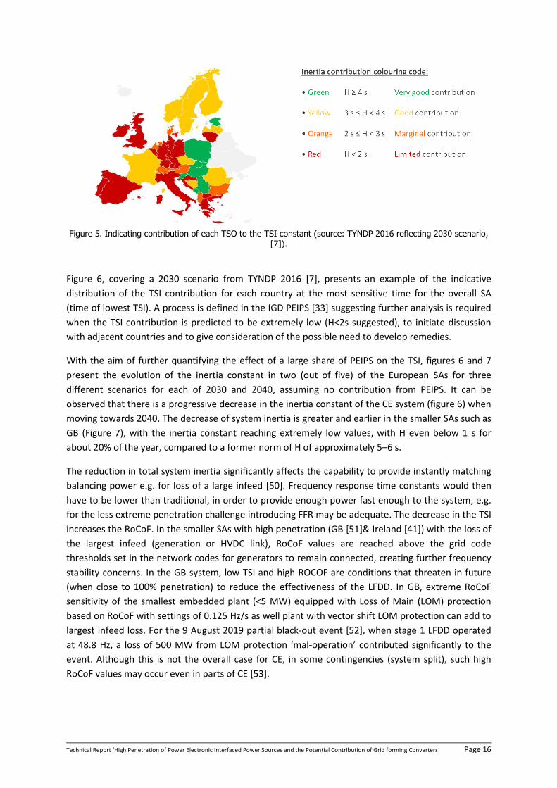
Figure 5. Indicating contribution of each TSO to the TSI constant (source: TYNDP 2016 reflecting 2030 scenario, [7]).
Figure 6, covering a 2030 scenario from TYNDP 2016 [7], presents an example of the indicative
distribution of the TSI contribution for each country at the most sensitive time for the overall SA
(time of lowest TSI). A process is defined in the IGD PEIPS [33] suggesting further analysis is required
when the TSI contribution is predicted to be extremely low (H<2s suggested), to initiate discussion
with adjacent countries and to give consideration of the possible need to develop remedies.
With the aim of further quantifying the effect of a large share of PEIPS on the TSI, figures 6 and 7
present the evolution of the inertia constant in two (out of five) of the European SAs for three
different scenarios for each of 2030 and 2040, assuming no contribution from PEIPS. It can be
observed that there is a progressive decrease in the inertia constant of the CE system (figure 6) when
moving towards 2040. The decrease of system inertia is greater and earlier in the smaller SAs such as
GB (Figure 7), with the inertia constant reaching extremely low values, with H even below 1 s for
about 20% of the year, compared to a former norm of H of approximately 5–6 s.
The reduction in total system inertia significantly affects the capability to provide instantly matching
balancing power e.g. for loss of a large infeed [50]. Frequency response time constants would then
have to be lower than traditional, in order to provide enough power fast enough to the system, e.g.
for the less extreme penetration challenge introducing FFR may be adequate. The decrease in the TSI
increases the RoCoF. In the smaller SAs with high penetration (GB [51]& Ireland [41]) with the loss of
the largest infeed (generation or HVDC link), RoCoF values are reached above the grid code
thresholds set in the network codes for generators to remain connected, creating further frequency
stability concerns. In the GB system, low TSI and high ROCOF are conditions that threaten in future
(when close to 100% penetration) to reduce the effectiveness of the LFDD. In GB, extreme RoCoF
sensitivity of the smallest embedded plant (<5 MW) equipped with Loss of Main (LOM) protection
based on RoCoF with settings of 0.125 Hz/s as well plant with vector shift LOM protection can add to
largest infeed loss. For the 9 August 2019 partial black-out event [52], when stage 1 LFDD operated
at 48.8 Hz, a loss of 500 MW from LOM protection ‘mal-operation’ contributed significantly to the
event. Although this is not the overall case for CE, in some contingencies (system split), such high
RoCoF values may occur even in parts of CE [53].

Technical Report ‘High Penetration of Power Electronic Interfaced Power Sources and the Potential Contribution of Grid forming Converters’ Page 17
Figure 6. Inertia constant in the CE system for given percentage of hours per year under various grid development scenarios, [44].
Figure 7. Inertia constant in the GB system for given percentage of hours per year under various grid development scenarios, [44].
1.2.2 System split
For the case of the CE power system, rare events such as system splits (currently experienced once in decades), becomes critical under high penetration levels of renewable generation sources. System split is identified as a grid extreme contingency leading to separation of the system into asynchronous zones. Exports and imports before the system split event become power imbalances for the separate islands after the split. A system split is more likely to occur across highly loaded weak transmission corridors. Developments of the European Electricity Markets are leading to the transit flows gradually increasing in magnitude, and they are more volatile. The potential imbalance after a rare system split which the systems need to survive is expected also to increase, bringing the system to its physical limits in terms of balancing capability.
A system split event could lead to a situation which is outside the pre-defined limits for frequency containment reserves (3 GW in CE). The most common remedial actions are LFDD, LFSM-U and LFSM-O. It is uncertain and hard to predict when and under what conditions a system split case will occur and what parts of the system will be split. Within ENTSO-E (System Protection & Dynamics), a methodology has been developed for the analysis of system splits [54]. The analysis has also been validated by comparison of recordings of real past events, including the 3-way split in 2006 shown in

Technical Report ‘High Penetration of Power Electronic Interfaced Power Sources and the Potential Contribution of Grid forming Converters’ Page 18
figure 8, in which the capabilities provided by the running SGs contributed greatly to system stability and the avoidance of system collapses. Further work on long-term frequency stability scenarios with less synchronous generation in operation are in progress and expected to give rise to relevant requirements [53]. The expected values of unbalance for future system development are expected to be 40% with a RoCof of more than 2 Hz/s [9], [55]. The latter, in conjunction with the expected reduction in TSI, presents risks to the overall system security. LFDD can be ineffective when inertia is low and power deficit is high (as may be the case with a system split) because the ROCOF can be so high that LFDD is not fast enough to halt frequency drop. As an example, in Australia, AEMO has determined that ROCOF must be less than 3 H/s to allow LFDD to operate effectively and inertia should be maintained to ensure this for all secured events (i.e. excluding system splits). It is worth noting that the RoCof observed during the Australian black-out event was 6 Hz/sec [56].
Figure 8. The system split event that occurred in the CE system in 2006.
1.2.3 Short-circuit power levels
Already today in many countries and regions, different levels of short circuit power levels are
observed / reported, mainly between central areas and areas at the system edges. This difference
will increase in the future, raising both stability but also political questions. References [51], [57]
from National Grid SO reflect and quantify the expected reduction in the short circuit power levels in
the transmission system. In general, the short circuit power levels trends are regional, different
across different SAs and operating conditions.
The overall consequence of low system strength is varied and complex across all categories of system
stability (rotor angle, voltage and control interactions). The direct effect of the reduction in the short
circuit power levels in the network is reflected in the deeper (in the medium and low voltage
network) and widespread (in geographic area) voltage dips in the event of severe transmission
network faults. The latter would affect the short term voltage stability and moreover, the rotor angle
stability of remaining conventional synchronous generation units (reducing the critical clearing times).
Several TSOs [9] have reported loss of devices in the context of fault-ride through capability. These
TSOs have mentioned as the main reason the reduction of the short circuit power levels and the
propagation of voltage dips which resulted in trips from under-voltage protection. Clearly, outages of
such nature would affect the frequency stability and would have a more global system effect under
high penetration of PEIPS.
With regard to PEIPS, it is well known that their stable and robust operation is affected significantly
by the correct operation of the phase-locked loop (PLL) modules. In weak grid connection
environment, the stable and robust operation of the PLL along with the application of vector current
control loops (grid following) could be a potential reason for PEIPS instability.

Technical Report ‘High Penetration of Power Electronic Interfaced Power Sources and the Potential Contribution of Grid forming Converters’ Page 19
1.2.4 Rotor angle stability
Rotor angle stability refers to the ability of the SGs connected to system to remain in synchronism when subjected to grid disturbances. With regard to the rotor angle stability, both small and large signal, the following two concerns are identified in [9]:
• Introduction of new power oscillations and/or reduced damping of existing ones.
• Reduction of transient stability margins.
1.2.5 Voltage stability
Voltage stability is associated with the capability of a power system to maintain stable voltage
magnitudes during both normal and disturbed conditions. Key to voltage stability are the system
loads and the dynamic behaviour of sources during disturbed conditions, in terms of active and
reactive power injections. Voltage instability occurs in the form of progressive voltage rise or fall,
known as voltage collapse. SOs are responsible for controlling voltage, so that it remains between
specific limits, both in steady and transient states, and could rely on the assistance of the producers
connected to its grid to do so. Injection or absorption of reactive power at each node induces voltage
differences between nodes which become more significant under high penetration of PEIPSs. Thus,
with regard to voltage stability, concerns as identified by TSOs in [9] are summarised as:
• Loss of generation in the context of fault-ride through capability
• Voltage dip-induced frequency dip
• Lack of reactive power sources
• Excess of reactive power sources
• Altered static and dynamic voltage dependence of loads
• Inadequate support to restore system voltage immediately post fault
Analysis of the extreme case of 100% PEIPS penetration [18] demonstrates that a response is
required in the first quarter cycle (within 5 ms) to avoid system collapse. Moreover, studies
presented in [12], [10], [58] have shown that the disconnection of conventional units has resulted in
significant control interactions and unstable operation of wind power plants in cases with high PEIPSs
(both in normal and fault conditions).
1.2.6 Other instabilities relating to fast dynamics of power converters
Further concerns include low synchronising torque (power) between generation sources, to
overcome sudden voltage angle disturbances (at the fundamental frequency). The issue of Sub
Synchronous Resonance in context of interactions with conventional machines is likely to become
more complex as operating conditions become more variable.
• The adverse control interactions between converter controllers (connected electrically close) is becoming a more significant issue. Such interactions may become visible as Sub Synchronous Resonances (SSR) or Super Synchronous Instability (SSI also called Harmonic Instability). As PEIPS becomes dominant, these interactions may no longer remain local [31], [59].
• In the absence of SGs, the system may lack ‘sinks’ to correct low order system harmonics
including inter-harmonics as well as lacking ‘sinks’ to correct phase unbalance.

Technical Report ‘High Penetration of Power Electronic Interfaced Power Sources and the Potential Contribution of Grid forming Converters’ Page 20
2 Power System Needs under High Penetration of PEIPSs: The need
for Grid Forming Converters
2.1 Classes of Power Electronic Interfaced Power Sources arising from IGD
HPoPEIPS
The previously issued IGD HPoPEIPS [33] introduced 3 levels of capabilities of PEIPSs using the terms
Classes 1, 2 and 3, with Class 1 as the highest capability and Class 3 as the lowest. Following further
consideration, to ensure greater clarity regarding the progression in requirement, the order
presented here has been reversed, with Class 1 being the basic level, Class 2 reflecting advanced
control (typical reflecting recent code requirements) and Class 3 defining the capability needs
expected in the future context of high penetration of PEIPS. Class 2 is further subdivided into A
(lowest), B and C (highest). These classes cover renewable energy defined in Network Connection
Codes as PPMS as well as HCSs. A brief high level description for these classes is given below. Class 3
includes the capabilities of Class 2 and Class 2 in turn, encompasses the capabilities of Class 1. For
full details of existing requirements the CNCs [60], should be consulted along with their
implementation in each country in national documents [61].
2.1.1 Class 1 Power Park Modules
Class 1 PPMs represent the basic level of grid-connected converter functionality, with a main focus
on basic converter survivability, reflecting requirements for the smallest (Type A) PPMs. HCSs with
only Class 1 capabilities are not covered in CNCs.
Listing of system needs / with respect to PPM capabilities
Basics PPM – with focus on survival
• Full frequency operating range
• Full voltage operating range
• Basic reactive controls – e.g. Unity Power Factor
• LFSM-O
• Complies with local power quality requirements (e.g. harmonics / unbalance current)
2.1.2 Class 2 PPM / HCS
A Class 2 PPM / HCS has ‘Advanced Control’ and additional capabilities over and above a Class 1 PPM.
It is possibly subdivided into 2A, 2B and 2C (2C highest). The listing of system needs with respect to
PPM/HCS capabilities, reflecting CNCs’ [60]progressive requirements for gradually larger PPMs
(Types B, C and D) as well as some non-mandatory capabilities (2C), is as follows:
• Fault Ride-Trough 2A
• Voltage control – steady state 2A
• Voltage control – dynamics 2B
• Voltage control – at P=0 2C
• FSM 2B
• LFSM-U 2B
• Provides damping 2C
• Fast Fault Current Injection (FFCI; see IGD) 2C

Technical Report ‘High Penetration of Power Electronic Interfaced Power Sources and the Potential Contribution of Grid forming Converters’ Page 21
o FFCI – Periods B + C for Positive Phase Sequence and Negative Phase Sequence (PPS
& NPS)
o FFCI – Periods B + C provide bias choice between reactive & real current
2.1.3 Class 3 PPM / HCS
Class 3 PPMs or HCSs shall, in addition to capabilities of Class 2C, be capable of supporting the
operation of the ac power system (from EHV to LV) under normal, disturbed and emergency states
without having to rely on services from SGs. This shall include the capabilities for stable operation for
the extreme operating case of supplying the complete demand from 100% converter based power
sources. The support services expected are limited by boundaries of defined capabilities (such as
short term current carrying capacity and stored energy). Transient change to defensive converter
control strategy is allowed (if it is not possible to defend the boundaries), but immediate return is
required.
In addition to capabilities of PPMs or HCSs of Classes 1 and 2, Class 3 may in future provide PPM or
HCSs controls with single cycle support services allowing 100% power electronic penetration,
including in headline terms (further info follows later):
• Creates system voltage (does not rely on being provided with firm clean voltage)
• Contributes to Fault Level (PPS & NPS within first cycle)
• Contributes to TSI (limited by energy storage capacity)
• Supports system survival to allow effective operation of LFDD for rare system splits.
• Controls act to prevent adverse control system interactions
• Acts as a sink to counter harmonics & inter-harmonics in system voltage
• Acts as a sink to counter unbalance in system voltage
A description of one practical implementation is as follows: The control strategy of grid forming PPMs
or HCSs provides an inherent performance resulting from presenting to the system at the connection
point a voltage behind an impedance, in effect a true voltage source.
There could in future be differentiation between controllable contributions from GFC (further
freedoms of design) and inherent contributions from SG to these 7 capabilities.
2.2 Requirements for Grid Forming Power Electronic Interfaced Power Sources
For grid forming capability of Class 3, the requirements are listed above in 2.1.3. They are described
individually in the following sub-sections 2.2.1 to 2.2.7 with respect to performance aspects in order
to support up to 100% PEIPS penetration and are relatively high level descriptions of desired
performance.
Other aspects are collated thereafter across the requirements covering:
• 2.3 Operational boundaries for GFC performance
• 2.4 Cost considerations
• 2.5 Must run units
• 2.6 SCs
• 2.7 Spatial distribution of Grid Forming Units or must run units
• 3 Proposed tests and benchmarking

Technical Report ‘High Penetration of Power Electronic Interfaced Power Sources and the Potential Contribution of Grid forming Converters’ Page 22
2.2.1 Create system voltage
To provide instant power to suddenly changing loads in an electrical power system, there is a need
for PPMs and HCSs with a voltage source characteristic. In this section, the most important
characteristic requirements for components providing this capability are outlined.
General Characteristics and fundamental capabilities
The PPM or HSC provides a three-phase voltage. In the first case, within the capability of the source
(especially in terms of current and power limits), the voltage is maintained in amplitude, frequency
and phase angle independently from a load connected to the source. In the latter case, the resulting
load flow depends on loads and current sources in the system only. The basics of various options of
GFC controls are explored as presented in [10], [18], [58]. An early national draft Grid Code
requirement (not mandatory, but paid for capability) is given in [38] calling for ‘capable of operating
as a voltage source behind a reactance over a frequency band of 5Hz to 1kHz before, during and after
a fault’.
Since in large interconnected power systems this capability for the system cannot be covered by a
single PPM or HSC, there is a need for the PPM or HCS to be capable of running in parallel with other
AC voltage sources. To provide a high robustness and modularity, inherent mechanisms shall be
implemented that lead to stable operating points without the need of control setpoints given by an
external entity for the means of parallel operation (e.g. f(P)-droop).
The resulting amplitude and frequency of the voltage at the terminals of the PPM or HSC may
depend on load, capability, internal control and optional external control setpoints in order to ensure
stable operating points of the power system. Single Phase PPMS may in future contribute to system
dynamic damping (increase of SCR and Inertia), but will usually not provide voltage source
capabilities (voltage and frequency). An operation as voltage source would require additional
hardware (supervisory control, protection handling) and safety procedures not adequate for small
installations.
Further important, more detailed and optional characteristics and quality criteria:
• Independency
o The PPMs or HCSs capability of providing a system voltage does not depend on the
existence of an external AC voltage source.
• Dynamic Capability
o Ride through and maintain synchronism during transient events such as grid faults
and load steps in the system
o Capability to supply linear and nonlinear loads of active and reactive power with a
supply voltage of commonly accepted quality (specify e.g. THD_U at given THD_I)
stationary
o Transient active and reactive power need / demand resulting from load steps can be
fulfilled
o The capability to limit and control the rate of change of voltage angle in transient
conditions in order to ensure overall system stability. In GB the ‘Stability Pathfinder’
[39] section ECC6.1.19.3(xvi) of the draft Grid Code specifies the withstand capability
of large voltage angle changes of 200 degrees lasting no longer than 5 ms and 90
degrees lasting no longer than 60 ms.

Technical Report ‘High Penetration of Power Electronic Interfaced Power Sources and the Potential Contribution of Grid forming Converters’ Page 23
2.2.2 Contribute to fault level / fault current contribution
The overall objective of an adequate fault current contribution consists in limiting the impact of a
grid fault (e.g. short circuit on transmission level) on generators and consumers in the wider area of
the fault, and as such avoids the risk of immediate voltage collapse. In addition, the functionality of
protection equipment in the grid has to be ensured [62], [63], [64], [65] .
The grid forming converter should provide an injection of current, which in case of low impedance
faults is limited to the converters’ overcurrent capacity. The desired behaviour during fault depends
on fault location, fault type and time interval of fundamental period, see [33]. In [18] emphasis is
attached to speed of delivery, suggesting that for 100% penetration, delivery within the first quarter
of a cycle (5 ms) is essential.
Protection system in the high voltage grid requires sufficient amplitude of fault current in the first 20-
30 ms after the fault. The aim of fault level contribution from PEIPS (PE connected equipment) is to
ensure the minimum voltage drop seen by other assets (especially more distant from the fault) to
prevent tripping due to under-voltage protection and to help keep the power system stable (if in a
100% penetration scenario no sources contributed to fault level, then a fault could trigger shut –
down, unstable voltage recovery or unsafe operation of the system). Existing protection schemes
should be revised once requirements to GFC for high penetration of PEIPS have matured and settled.
Challenges for existing protection systems in high penetration of PEIPS, particularly distance
protections, are discussed in [62], [63], [64], [66].
The voltage source characteristics of a GFC means that it would contribute to the system strength of
the power system. The contribution to the system strength of a GFC can be assessed by the
characteristic small signal short circuit impedance and by the maximum current contribution by the
GFC, for definitions see [33].
Current control / clipping
The grid forming converter control, regardless of the technology implementation, behaves as a
Thevenin source and impedance. The voltage source is controlled in frequency and in amplitude, and
the impedance can be emulated, a real impedance or a combination. As such, the GFC contributes to
system strength. Regardless of the technology implementation, the GFC must have a behaviour like a
Thevenin source and impedance and, at the same time, the GFC must be able to protect itself by
limiting the current according to the converter overcurrent capacity. By this, the GFC will respond to
a voltage change with a large fast current as a voltage source behind an impedance, whereby
exceeding the extreme current and power limits is prohibited by modifying the voltage angle or
magnitude.
If current limitation is necessary during voltage drops and phase (voltage angle) shifts/changes in the
network, two options will be available: a) switch over to current control during the fault period in
order to limit the current to below the rated current capacity of the converter, b) implement some
current clipping features (done either by HW or SW depending on converter technology), for
examples of the latter with SW. It is, at the present time, an unresolved problem for the power
industry to investigate how the current should be prioritised once the GFC hits its current limit during
a fault, i.e. should the current be proportionally scaled or should active or reactive power be
prioritised?

Technical Report ‘High Penetration of Power Electronic Interfaced Power Sources and the Potential Contribution of Grid forming Converters’ Page 24
Comparison with existing network codes
The existing national implementations of European wide CNCs [60] deal differently with the topic of
fault current in different countries. Some countries (ex. [14]) are already moving forward to a more
detailed specification of requirements, including the extreme speed of operation (5 ms). This (5 ms)
is adopted in the GB specification of the Stability Pathfinder ‘Draft Grid Code–Grid Forming’ [14].
Much work still remains in terms of specifying and agreeing on the desired response in the new
context of high penetration of PEIPS.
2.2.3 Sink for harmonics
Key points summary
Definition: Provide a passive, damping response in the harmonic frequency range using harmonic
current flow with the effect of improved voltage quality at the point of connection. The characteristic
could be inductive, similar to a synchronous machine, or inductive-resistive, providing superior
performance to a synchronous machine.
Allocation of current-carrying capacity to this function:
• Current-carrying capacity (headroom) is required to inject harmonic currents at required
operating points.
• THD vs. individual orders: The current headroom must be appropriately distributed across
the relevant harmonics. Synchronous machines’ harmonic impedances increase linearly with
frequency.
• Depending on the voltage level of the point of connection: the lower the voltage level the
higher the planning level for voltage harmonics.
Prioritisation:
• Power quality is more of a concern in steady-state. Thus, this feature should receive lower
priority than dynamic aspects such as Fault Ride-Through (FRT) or frequency support.
• As a result, the current headroom could be used by other features when they are active.
(Fair) Share of contribution:
• A proportional sharing of harmonics damping between many units is both necessary and
desirable.
• Both the physical impedance (filters, transformers) and additional virtual impedances should
be considered to utilise allocated headroom accordingly and provide similar characteristics
for physically different units
Reference [23] contains an example laboratory implementation of the above and [14] section
ECC6.3.19.3(x) contains a draft non-mandatory Grid Code specification.
Identify relevant frequency range: e.g. < 2 kHz
Performance
Reduce voltage harmonic content at the connection point by providing a current path for non-
fundamental frequencies up to a limit of e.g. 2 kHz. The harmonic impedances of synchronous
machines are inductive, enabling the flow of harmonic currents and thereby damping through the
Technical Report ‘High Penetration of Power Electronic Interfaced Power Sources and the Potential Contribution of Grid forming Converters’ Page 25
resistive properties of other components. Inverters could mimic the inductive behaviour of
synchronous machines, or, in the lower end of the proposed frequency spectrum, provide inductive-
resistive behaviour with increased damping compared to synchronous machines [67].
The required current flow is to be drawn from an allocated headroom, which must be available for an
indefinite time to permanently provide damping in steady-state conditions.
Impedance may be increased to limit harmonic currents into the equipment (limit headroom),
whenever the harmonic voltage levels would lead to current flows exceeding the allocated headroom,
or when other features of higher priority impinge on the available headroom. Features of higher
priority include those used during contingencies.
The headroom must also be allocated across the relevant harmonic frequency spectrum, to cover
cases where damping cannot be provided sufficiently for all orders of harmonics. The harmonic
impedances of synchronous machines increase with frequency, indicating a proportionally higher
current allocation for lower frequencies.
The damping provided could be proportionally shared according to the power output level of the
involved units. A combination of physical and virtual impedances could be used to compensate for
variations in physical impedances.
This performance stands in contrast to typical grid code requirements to-date as well as the standard
IEC 61400-21 [68] for measurement and assessment of power quality for wind turbines, which focus
on harmonic content in current emissions of inverter-based generation units rather than on voltage
harmonics. Requiring voltage harmonic compensation will inevitably induce variation in the harmonic
current emission of the inverter-based unit [69].
2.2.4 Sink for unbalances
Performance
Considerations for unbalance affected by reduction of NPS sinks from decreasing number of SGs are
in many ways similar to above considerations for harmonics.
Provide low NPS impedance. The NPS impedance may be increased to limit the negative sequence
current. For a draft national non-mandatory Grid Code see [38] section ECC6.3.19.3 (xxi) and for
laboratory implementation, see [23].
2.2.5 Contribution to inertia
The main benefit of inertia from synchronous machines is that their rotating mass provides
inherently stored energy that, in combination with the voltage source characteristic of a synchronous
machine, counteracts voltage angle, amplitude and frequency perturbations and therefore reduces
the RoCoF in case of load steps and helps to limit voltage steps by providing a source of active power
if needed.
Definitions
To appreciate the complexity of the subject of inertia it is recommended to read the definitions in
the Annex 5 (Terminology and Definitions) to obtain clarity regarding inertia, synchronous machine
inertial response, synthetic inertia and FFR. It is common for these terms to be misrepresented. In

Technical Report ‘High Penetration of Power Electronic Interfaced Power Sources and the Potential Contribution of Grid forming Converters’ Page 26
the power system context, the inertial response is defined as the energy exchanged between the grid
and the rotor of an electrical machine in the case of a frequency event due to the rotor moment of
inertia. These characteristics are defined in the swing equations by the gain and damping factors,
further developed in Annex 5.2. This same framework can be used to characterise the inertial
response regardless of type of converter implementation.
Performance
GFC is one method of dealing with the concern of diminishing TSI, illustrated in figure 4 in Section
1.2.1. As illustrated with the wide variety of frequency response capabilities as discussed in Annex 5,
the ‘inertial characteristics’ of a grid forming converter need to be defined in a measurable way to
provide converter designers and operators with a common language that can be used when
discussing and agreeing on a particular inertial characteristic.
An inertial response, by definition, requires an exchange of active power between the grid and the
equipment delivering the response whereby the total energy exchanged depends on both the event
initiating the inertial response and the inertial characteristics of the equipment. For a GFC, where the
inertial characteristics are given by the parameterisation of the control system, it is important to
consider and ensure that the system behind the GFC has the capability to deliver the energy to match
the programmed inertial characteristics across the expected operational boundaries, cf. section 2.3.
Whether the additional energy can be made available by existing equipment in the plant, like
rotating mechanical structures, from headroom created for PV or whether a dedicated energy
storage system is required will depend on several factors; including the per unit inertial requirements
versus the capability of the plant, the operational boundaries for the inertial characteristics, the
expected firmness of the response, and the attitude towards allowing the extraction of inertial power
to move the plant to a suboptimal operating point resulting in a lower power in-feed. These aspects
are discussed further in section 2.3.
A TSO may assume that the inertial response provided by a GFC would be similar to that provided by
a synchronous machine, in which a value of H would have a familiar meaning, with an underdamped
response. However, when providing an inertial characteristic from a GFC a choice is now available in
terms of the level of damping that is designed into the characteristic, e.g. critically damped or even
overdamped. Whereas a higher level of damping would give the GFC a less oscillatory response, it
also affects the rate of change of power when subject to a frequency event; and given that therefore
a GFC is an actual design choice, the mentioned trade-off should be investigated to identify a sensible
range for the damping level. In the converter the delivered response can either be internal damping
that does not exchange damping power with the ac system or external damping with exchange of
power with the external system, but which would require a differential type control on top of the low
bandwidth voltage source behaviour of the GFC. These aspects are expanded on in Annex 5.2.
One major challenge when defining performance indicators for the inertial contribution of converters
is to allow for different reference values due to different system needs without specifying the actual
control implementation. From the manufacturers’ perspective, it is important that a generic inertial
characteristic emerges that can be adjusted for specific requirements. It may in future be possible to,
within the hardware capabilities, vary the inertial and damping gains based on varying grid needs.

Technical Report ‘High Penetration of Power Electronic Interfaced Power Sources and the Potential Contribution of Grid forming Converters’ Page 27
Relevant references include trial implementation in a wind farm [35], a BESS installation [16] and
criteria [53].
2.2.6 System survival to allow effective operation of LFDD (Load Frequency Demand
Disconnection)
The challenges of extremely rare situations (typically once in multiple decade system split events
combined with high PEIPS penetration) assuming last resort (LFDD) is called upon:
• LFDD may not succeed during system splits with close to 100% PEIPS penetration of Class 1 and Class 2 capabilities, due to inadequate volume of SGs and hence inadequate system strength in the newly formed island, resulting in immediate system collapse.
• The limited ability of the running generation to provide a short window (100s of ms) of voltage, frequency and angle stability following the extreme event. Faster new services such as fast frequency control (with 0.5-1 s response time) may provide some help in this context (or at least be ready to take over the provision of support from the fastest providers such as GFC). Faster still is the potential for short duration (e.g. li-ion) storage, which already has all the necessary hardware to provide some GF capability and a high technology readiness. These low cost options should be evaluated in follow up studies first before wording requirements.
Locational issues for GFC installations are important in the provision of minimum system strength.
This relates to both the general geographic spread and possibly the voltage level it is injected at. This
influences the ability to provide an effective support close enough electrically to potential major
transmission system splits. This is further discussed in section 2.7.
Performance
Studies [10], [12], [22], [70] have shown that a power system operated in the High Penetration range
of PEIPS (60–100%) will, following a major fault & subsequent power imbalance be at risk of total
collapse before the LFDD has implemented its load reduction (to roughly restore the demand vs.
generation power balance). LFDDs are set to operate at low frequencies in stages (in CE starting with
load disconnection of stage 1 (5–10% of total demand) at 49.0 Hz). Study [70] demonstrates how,
even close to 100% PEIPS, a most severe system split could be survived by both islands in a two way
split, even with a massive imbalance, if a certain level (indicatively 30%) of GFCs is introduced. This
study was based on a current capability of 1.5 pu reducing to 1.25 pu in 80 ms. The other 70% split
50/50 between Classes 1 and 2B would allow system survival with up to 30% or possibly 40%
imbalance. This level of capability is reflected in the draft non-mandatory national Grid Code for Grid
Forming capability [38], at the start of a tendering process for delivery respectively from 2020 [39]
and from 2023 [40].
GFCs which additionally provide inertial support typically (i.e. assuming design limits are not
breached) operate as a voltage source behind an impedance whose magnitude phase and frequency
only change slowly in response to events. Consequently, the only parameter which normally changes
rapidly is current. The currents are therefore determined by the network and not the convertor
control systems. Any given switching event or fault has little or no instantaneous effect on SG rotor
and GFC internal operating angles. However, such events do typically result in large changes in bus
Technical Report ‘High Penetration of Power Electronic Interfaced Power Sources and the Potential Contribution of Grid forming Converters’ Page 28
bar angles (vector shifts), which leads to the subsequent changes in P, Q, V, I and frequency. In the
case of system collapse, [25] and [71] opens up for GFC-based support of restoration.
There is some evidence – [10], [12], [72] – to indicate that grid forming technologies with limited inertial capacity (equivalent H) or headroom (i.e. the ability to increase power output before hitting power limit) are still more beneficial to grid stability than conventional vector current control convertors. Placing convertors in GFC mode could therefore be more beneficial to grid stability than leaving them in current control mode of operation, even if they are close to their maximum power output or have little capacity to provide significant equivalent inertia [12], [58].
Further studies for CE within ENTSO-E in a Memorandum entitled ‘Minimum required inertia for
Continental Europe’ [55], [45] have explored the relationships of key LFDD parameters for system
survival following system splits with various degrees of severity (imbalances from 10% up to
40%). This has not yet been turned into a target value. Further analysis of system splits for CE based
on marked data is covered in [73].
To ensure power systems can survive, at least in part without total collapse under these very rare
most extreme operating conditions (such as large-scale system splits, e.g. as 4 Nov 2006, see Figure
8), distributed fast acting dynamic support for a range of stability challenges (frequency, voltage and
angle) is needed. These have been delivered in the past mainly by SGs. When SGs are not in
operation, alternative means are required to undertake these tasks. Studies indicate there is the
ability to avoid system collapse using very fast performance as provided by GFC [15], [72] converters
in adequate volume and with adequate geographical spread (close enough to the location of the
split).
Grid Operator System Studies should consider the grid’s ability to survive a system split or generation
loss scenarios and determine minimum necessary peak active and reactive power output and
minimum necessary energy output with suitable control models. Realistic future penetration
scenarios should be used (see section 1.1). Low cost solutions focused on control system changes
incurring as little as possible extra hardware cost (see below) should be considered first in these
studies (e.g. within 1 pu current for new PEIPSs assuming no retrospective implementation) and
higher cost solutions (with >1 pu and/or even retrospective application) should only be added
subsequently if necessary. It should be noted that the 2019 wind farm GFC trial [35] was
implemented retrospectively to a 2016 installation.
An RMS type simulation can be sufficiently accurate [70], [72], although increasingly TSOs are finding
that these may be optimistic in the context of the limits of stability when the penetration approaches
100%. An EMT type simulation may be beneficial for RMS method validation but practically
challenging to implement in an operational environment. To support the grid during such scenarios,
near instantaneous holistic support are required (covering the variety of services encompassed under
the heading GFC), especially near the split location.
2.2.7 Prevent adverse control interaction
When a power converter is connected to the electrical grid, the overall network resonances vary
because of: (i) the connection of the converter passive components and, (ii) the impact of the
converter’s active behaviour.
The interaction between the network resonances and the active behaviour of the converter is
characterised by the natural frequencies of the network and the damping provided by the network,
other generators, loads and the converter, which varies with every operating condition.

Technical Report ‘High Penetration of Power Electronic Interfaced Power Sources and the Potential Contribution of Grid forming Converters’ Page 29
Electromagnetic natural frequencies appearing within a region in which the converter presents
negative resistance behaviour may result in instability if the network itself does not provide enough
damping to compensate. A generic example composed of a system with a VSC and a network with a
given frequency-dependent behaviour is shown in the Cigre WG B4.67 brochure [74]. The control
dynamics together with interaction with the network (represented by the Thévenin impedance Zh)
are shown in figure 9. The reduction of the complete VSC to an equivalent admittance is also
illustrated in figure 10.
The connection of the converter to the network results in new resonant points determined by the
frequencies at which the impedance curve of the converter crosses the frequency dependent grid
impedance. The amplification factor is dependent on the angle difference at the crossing point. The
closer to 180 degrees the angle difference is (between the converter and the grid frequency
dependent impedance), the more amplified the resonance will be.
The stability phenomenon described here is related to small signal disturbances in a wide frequency
range. For this reason, the terms ‘harmonic stability’ or ‘super synchronous instability’ are sometimes
used. Contrary to small signal rotor angle stability, the interaction is not between the power system
and synchronous machines, but between converters or between converters and the grid (frequency
dependent grid impedance). In addition, sub-synchronous control interactions need to be similarly
considered. To capture the nature of the phenomenon, the grid connection point frequency
dependent impedance, as well as the power converter frequency dependent impedance, must be
described in a larger frequency range [75], [76], [77], [78], [78], [79]. The problem may, in a high
PEIPS context, include the description of the system reflecting an active network.
Figure 9. Example of a network composed of a VSC and a frequency-dependent AC system for the study of control interactions.
Figure 10. Dynamic interaction between the active VSC impedance and the network harmonic impedance.

Technical Report ‘High Penetration of Power Electronic Interfaced Power Sources and the Potential Contribution of Grid forming Converters’ Page 30
Besides the extreme case of instability, resonances coinciding with this region may also result in
sustained oscillations for several seconds with corresponding over-voltages and other adverse effects.
Current work on terms & definitions: Cigre WG C4.49 ‘Multi-frequency stability of converter-based
modern power systems’.
Performance
Converters are never passive (neither are synchronous machines). As the energy storage in
converters is smaller compared to synchronous machines (inertia), the power control loops of power
converters need to be faster for its protective (survival) and own stability purposes, thus resulting in
a broader control bandwidth.
• To define performance requirements for converters, the power system needs to be analysed
across the frequency range. Resonances due to passive elements (e.g. cable capacitances and
transformer inductances) or active elements (other converters) pose a risk for control
instability if they fall into the control bandwidth of the converter i.e. the frequency range
where the converter is active. Requirements have to be determined for a specific system.
One view is that ‘a general specification, which avoids control interaction and resulting
harmonic over-voltages in any situations’, might be very conservative and impossible to fulfil.
A contrary view in [38], [72] advocates a bandwidth limitation (5 Hz – 1 kHz) over which GFC
control should exhibit a Thevenin source behind an impedance type behaviour in order to
ensure stability for varying network topology over time and dramatically vary the short term
connection of generation. This control limitation specified in the draft GB Grid Code for Grid
Forming [38] mirrors SG excitation control requirements. It has a secondary aim to ensure
that rms based stability studies remain meaningful in the day-to-day system operation
environment. The effectiveness of this methodology in terms of delivering certainty of
stability is under review [80].
• Optionally, damping can be provided in a specified frequency range (active behaviour with
sufficient phase margin). This is related to the requirement for reducing harmonics in the
system, outlined in section 2.2.3, although the latter mainly refers to steady state.
Study
The list below relates to the testing of systems with different system sizes (the extent of required
studies decreasing from systems with a large number of converters to systems with only a few
converters).
• Small-signal stability analysis. For power systems of nontrivial size, modal analysis is most
conveniently carried out using a state-space representation of the system dynamics. Defining
the mode frequencies and damping in this way is usually the first step in modal analysis. To
determine the degree of participation of individual state variables in each of the modes,
mode shapes and participation factors are useful. Contrary to small signal rotor angle
stability, for control interaction the power system must be described in a wider frequency
range.
• Impedance-based stability analysis in the frequency domain. This is a small signal analysis
approach. It is especially of interest for the analysis of one converter against a larger system
with many involved active devices. The methodology to assess the stability of two active
networks is under review. Discussion on this methodology is given in [75], [76], [77], [81],
[78].

Technical Report ‘High Penetration of Power Electronic Interfaced Power Sources and the Potential Contribution of Grid forming Converters’ Page 31
• RMS-simulation (dynamic phasor representation, classical stability simulation type) may be
an option for the analysis of large systems, as long as the effects to be analysed are
controllers possibly oscillating against other controllers but not against passive network
components, and as long as the frequency range of interested does allow a steady-state
representation of passive network components. Special care has to be taken for sufficient
modelling, as the models of controllers usually implemented for RMS simulation are typically
simplified, for example only positive sequence representation, measurement filters and
measuring value converting only represented by a simple PT1 block. Model validation is of
crucial importance.
• EMT-simulation (no real-time required) with validated models (or even with models which
have the firmware of the device embedded, Software-In-the-Loop [SIL] and Dynamic-Linked-
Library [DLL]).
• Real-time simulations (Hardware in the Loop [HIL] or SIL).
Testing procedure
A relevant testing procedure is provided in standard [82], [83] for railway supply systems, and is
described below. Such systems feature a limited number of involved parties (SOs, network users,
manufacturers) and converter types. Its applicability for large transmission and distribution grids with
many stakeholders and large numbers of different converter types and sizes needs to be assessed in
practice.
The compatibility study, or compatibility test, is a process to demonstrate the compatibility of the
new element with the existing power system. It comprises the following steps:
SO:
1. Plan for compatibility check: The plan for a specific compatibility check when introducing a
new element in an existing power system defines the scope of the analysis, and the precise
tasks and responsibilities. The plan shall be agreed between all parties involved. The SO shall
be in charge of the compatibility study.
2. Characterisation of existing power system: Characteristics of the existing power system,
information relevant to the compatibility with the new element. Existing power system also
mean future infrastructure changes as foreseen by the SO.
3. Characterisation of existing converters operating on the network. If future expansion with
further converters is planned, the study may include them, as proposed by the SO.
4. Characterisation of existing operation conditions. If future operating conditions are foreseen,
the SO may include them in the study.
5. Characterisation of overall power system: This is the combination of the information from
steps 2, 3 and 4. It may be necessary to define different scenarios.
6. Theoretical analysis of overall power system: Investigation of compatibility aspects for
different scenarios. In a first step: confirm compatibility of the existing system. In a second
step: test potential new element.
7. Acceptance criteria for new element: The result from the theoretical investigations in step 6
is the particular acceptance criteria for a new element. The particular acceptance criteria
must be understandable and measurable when designing and testing a new element.
Manufacturer of the new converter:
8. Design / Engineering of new element, considering also the acceptance criteria defined in step
7.

Technical Report ‘High Penetration of Power Electronic Interfaced Power Sources and the Potential Contribution of Grid forming Converters’ Page 32
9. Characterisation of new element: The new element shall be modelled with respect to its
compatibility with other converters and the power system in general. The model shall be
validated in step 15 below.
10. Theoretical analysis of new element: At an early stage of the design, a theoretical analysis,
e.g. using computer models, shall check that the new element can meet the acceptance
criteria.
11. Testing in lab (HIL): Once the new equipment is built, it shall be tested on a test system to
verify that it meets the acceptance criteria as predicted by the theoretical analysis in step 10.
This set of tests can be part of a type test of the new element.
SO or third party in charge of compatibility study:
12. Test plan for compatibility study: A plan shall be made to define the tests necessary to
confirm as far as reasonably possible: 1) that the new element meets the acceptance criteria;
2) to ensure that the test reflects the reality. The tests shall also demonstrate the correctness
of the simulations done in step 10 and shall be limited to critical cases.
13. Testing in lab (HIL): Tests will be performed on a test system. These tests shall demonstrate
that the acceptance criteria are met. A failure to meet the acceptance criteria means
necessary modification of the new element. This series of tests is part of a type test of the
new element. The tests shall also demonstrate the correctness of the simulations done in
step 10 and shall be limited to critical cases.
14. Tests on real power system: Tests on the real system shall give confidence that the
acceptance criteria are sufficient to guarantee compatibility within the system after
introduction of the new elements. If these tests show compatibility problems despite the
compliance of the new equipment with the acceptance criteria, and after a check that the
test conditions were the same as those simulated, this means that the acceptance criteria
were not sufficient. If this is the case, an iterative process shall take place between involved
parties to find the necessary compromise to achieve compatibility. This set of tests is part of
a type test of the new element. The tests shall demonstrate also the correctness of the
simulations done in step 10 and shall be limited to critical cases.
15. Tests confirm compatibility: If both sets of tests in step 13 and 14 are successful, then
compatibility of the new element with the existing system has been demonstrated. This shall
be documented in a compatibility report.
16. End of compatibility check: With the successful completion of the compatibility study, the
new element becomes part of the existing power system. The responsibility for the
compatibility case no longer lies with the supplier of the new element. Any problem
occurring after will be the subject of iterative work between parties to find the necessary
solution to achieve compatibility.
For large transmission and distribution grids with many stakeholders and large numbers of different
converter types and sizes, the procedure described above may need to be simplified. Possible
simplifications can be:
• Grouping of typical power system characteristics (points 1–5 above), based on following
aspects: voltage level, expected mean electrical proximity of converters, types of converters
installed, first resonance frequency and system impedance angle at fundamental frequency
(natural damping of grid).
• Standard acceptance criteria (point 6–7) for the new element depending on the typical
power system characteristics described above.
• Standard test plans (point 12) and test systems (point 14) for the set of compatibility tests.

Technical Report ‘High Penetration of Power Electronic Interfaced Power Sources and the Potential Contribution of Grid forming Converters’ Page 33
Based on such a simplified approach, the compatibility design and testing only comprises point 8–16
above. The combination of typical power system characteristics and standard acceptance criteria can
be described by equipment classes. After successful type testing, the choice of equipment for use in
the power system can be made based on the equipment class. If possible, incremental definition of
acceptance criteria could be used, so that equipment suitable for a higher class is automatically
suitable for a lower class.
The definition of equipment classes and standard test plans and test systems may need to be
periodically updated to reflect the development in power systems. In this case, a procedure for
dealing with legacy equipment should also be determined.
From a TSO point of view, perhaps moving from modest PEIPS penetration (<60%) towards full
penetration (100%) with 100s or even 1000s of elements, the above method may be less suited than
in considerations of one or a few large elements (e.g. HVDC connections). Limitations of skilled study
resources are likely to make full implementation impractical. Therefore, TSOs may increasingly be
seeking control solutions that give greater inherent continued stable operation under a wide range of
conditions including future higher PEIPS penetration through additional connections and also
weather-related different operating conditions. It is hoped that GFCs may contribute to building
confidence in compatibility over a much wider range of conditions.
2.3 Operational boundaries for GFC performance
The performance of a GFC during a grid event, where an exchange of active and/or reactive power
between the converter and the grid is initiated, is dependent on the grid forming characteristics
being supported by the converter hardware in terms of headroom for the additional current and
availability of the requested active power in the context of the actual operating conditions. If the
converter has no headroom for the requested current, the control system must adapt into a
protective mode to avoid damaging the power hardware, which means rejecting the exchange of
active and/or reactive power that the grid event initiated. At this moment, the characteristics of the
power converter will change, the bandwidth will increase, and a control targeting control of current
will be initiated. For grid events involving active power there is also the consideration that the power
converter must be able to source or sink the energy as requested by the grid event.
It is the grid that is effectively exchanging active and/or reactive power with the converter where the
amount over time is given as a function of the characteristics of the event and the parameterisation
of the GFC. That is, for a GFC to retain its grid forming characteristics during a particular grid event
independently of the pre-event operating point of the GFC, the event must be within the limits that
the GFC was designed for. Operational boundaries will here be used to describe the range of
conditions for the power system within which the GFC is expected to retain its grid forming
characteristics. The operational boundaries must be defined by the entity, e.g. TSO, that is
requesting/purchasing the grid forming characteristics and include frequency range, df/dt, voltage
imbalance and phase step, and may be chosen more narrowly than the requirements for staying
connected. Care should be taken when outlining operational boundaries to ensure a level playing
field between different sites and technologies, as there is clearly a cost aspect involved with the
delivery of grid forming characteristics, cf. section 2.4.
The hardware requirements for a GFC are given as a function of desired grid forming performance
and the operational boundaries within which the grid forming characteristics should be operational.
Inertial response is, in section 2.3.1, used as an example as both current and energy considerations
apply, but other grid forming characteristics can be similarly treated.

Technical Report ‘High Penetration of Power Electronic Interfaced Power Sources and the Potential Contribution of Grid forming Converters’ Page 34
Selecting very wide ranges for the operational boundaries means that all the GFCs retain their
characteristics during more extreme system conditions and thereby help the power system ride
through the event, but it also means that more current headroom and larger energy sourcing
capabilities are required, which increases the cost related to converter power hardware. Opting for
narrower ranges for the system boundaries to keep the cost down implies that some or all the GFCs
change characteristics during the event into a protective mode, thereby leaving the power system
without the support previously provided by the GFCs. Detailed contingency studies are required to
assess the trade-off between system properties (e.g. range of ability to survive), GFC capability and
cost.
In the above, no assumptions have been made regarding the source of any additional active power
that is exchanged with the grid due to the grid forming characteristics. The reason for this is two-fold:
1. The requirement for active power exchange will, as discussed above, depend on both the
desired grid forming characteristics and the operational boundaries within which the
characteristics should be preserved.
2. Power converters are used as an interface between the power system and other equipment
performing some primary function for a wide range of applications and technologies with
different inherent capabilities and properties.
The energy must be available when required by the grid for the grid forming characteristics to be
preserved, but the source of the energy can be subject to commercial optimisation considering the
actual requirements and the inherent capabilities of the plant. To deliver a given requirement of
power versus time profile, different technologies may choose to:
• utilise inherent power overproduction capabilities in the plant,
• move the operating point of the plant to create capability for overproduction, or
• install energy storage to create capability for additional power in parallel with the primary
function of plant.
The choice will be dependent on both the inherent properties of the plant and the requirements for
overproduction. Here, higher requirements, i.e. power, energy and rate of change of power, and
firmer requirements, i.e. same level of response, is required irrespective of the operating point of the
plant and will likely encourage solutions with dedicated energy storage. If a power generator is
operated with maximum power point tracking, extracting additional active power implies that it will
move the generator away from its optimal operating point, which will then reduce the maximum
amount of power that the generator can physically produce. The option of extracting additional
power therefore comes with the cost of a reduced power production capability post-event. This has
been studied extensively for wind turbine generators and is often referred to as the ‘recovery period’
[84].
One possible compromise which may be worth considering in the future is the use of headroom
(tracking a fixed level below maximum power). Enabling could be limited to times when PEIPS output
is above a critical level (e.g. 70%), when the system stability otherwise would be exposed. During
these periods, experience shows that the market value of the RE production is low, even sometimes
negative, although legacy RE remunerations may be different. At other times normal maximum
power tracking could be allowed for wind and solar PV [28].

Technical Report ‘High Penetration of Power Electronic Interfaced Power Sources and the Potential Contribution of Grid forming Converters’ Page 35
2.3.1 Example: inertial response
The expected inertial response of a converter interfaced unit to a grid event will be inherently
interactive with the grid. That is, it is the characteristics of the grid voltage, i.e. phase and frequency
that determines the resulting power that will flow from the converter interfaced unit having a set of
pre-defined inertial characteristics.
The response requirements for the converter can be broken down into a disturbance in energy and a
peak current required for exchanging the disturbance energy. A converter with a given set of these
properties can only be configured for a specific inertial characteristic when the boundaries for
required survival of the grid (in context of rare extreme events) that it is connected to are known (the
network requirements). That is, it is the worst-case grid characteristics (conditions for which the
system is required to survive) that define requirements for disturbance energy and peak current (or
power). For events out of those operational boundaries, it is expected that the converter interfaced
unit delivers a non-linear response, with the main intention of ensuring that its hardware limits are
respected, although TSOs are likely to prefer a limitation of the GFC response rather than a total
mode change.
The energy that a synchronously rotating mass exchanges with a network when subject to a steady
state change in rotational speed is given by the change in stored kinetic energy between the two
rotational speeds. The analogy to a GFC equipped with an energy limited source, e.g. a storage
system, is that it is therefore necessary to know the frequency range (operational boundary) in which
the inertial characteristics should apply in order to design the required capabilities into the system;
an example of this is the draft national non-mandatory Grid Code [38], see section ECC6.3.19.3(xi).
The power that the inertial energy is being released with is a function of the RoCoF and the damping
of the inertial characteristics. This has two important implications for the design of converter units
that are to possess such characteristics: 1) a sufficient current window need to be designed into the
power converter to allow the power to be delivered on top of its pre-event operating point, and 2)
the energy source that is delivering the inertial power must support this power level and, additionally,
the rate of change of power, which is strongly influenced by the damping levels of the inertial
characteristics.
In summary, if the characteristics of the worst-case events and the requested or required inertial
characteristics are known, the hardware for converter and the energy source can be designed
accordingly. Alternatively, if already existing hardware is being deployed in a power system, the
inertial characteristics of the control software need to be configured to respect the hardware limits
for the design events of the power system.
2.4 Cost Considerations
Below, preliminary considerations only reflect hardware costs. Development, operational and
servicing costs, patent and licensing related costs, and certification and compliance testing costs will
have to be considered as well and depend on a variety of factors.
Grid forming converter control is fundamentally different from the control that is commonly
employed today and will, considering the general maturity level mid-2019, require a significant R&D
effort from converter manufacturers to develop their technology readiness level to today’s level for
current control. This includes:

Technical Report ‘High Penetration of Power Electronic Interfaced Power Sources and the Potential Contribution of Grid forming Converters’ Page 36
• control stability and interaction
• hardware development (both converter and, when required, energy storage)
• hardware re-dimensioning (both electrical and mechanical if additional stress levels are
imposed as a result of the grid forming operation)
• development and validation of client user models
• grid compliance testing and certification
• assessment of the wider impact on equipment design
• quantifying any impact on equipment capability across the entire operational envelope
• concept maturing and runtime
A GFC installed for system stability purposes can be developed as a standalone converter serving only
this purpose or the grid forming control and any additional hardware capabilities can be integrated
into converters that serve additional purposes, e.g. battery systems for fast frequency reserve or
power producers such as PV or wind turbines. Common to both concepts is that energy and current
headroom, as defined by the required grid forming performance and the system boundaries, must be
allocated if a firm response is required. The cost for the additional hardware will, as discussed in
section 2.3, be highly dependent on the required grid forming performance and the operational
boundaries within which the characteristics should apply. As performance is generally assessed at the
Connection Point, a choice arises in terms of delivering performance from the equipment performing
the primary function or by adding centralised equipment at the substation [24]. Whether it is most
cost effective to integrate the grid forming functions into a power converter serving other duties will
likely depend on the balance between savings from utilising existing infrastructure and design work,
set against the difficulty in integrating the grid forming functions with the primary duties of the
converter. Potential savings include:
• Re-use of components with inherent short-term overload capability such as power
transformers and cables
• Additional civil works are much less than that required for a complete stand-alone GFC
• Potential synergies between hardware installed for grid forming services and equipment for
primary duty
Potential challenges include:
• Difficulties in integrating the grid forming functions with the primary duties of the power
converter
• Additional hardware for grid forming services poses a potential risk of additional downtime
which affects the primary duties and thereby the revenue stream
• Ability to sufficiently isolate the structural components towards the power disturbances
caused by the active power exchange with the AC power system
The requirement for additional electrical hardware for higher current rating and, potentially, an
energy storage system is one of the sources of added cost for a GFC and is what enables the
converter to retain its grid forming characteristics across a wider range of operational boundaries. As
discussed in section 2.3, there is a decision to be taken about how wide the operational boundaries
should be; where the trade-off is between the cost of the GFC and the predictability of the response.
The impact in terms of system support and operation from operating a GFC without additional
hardware capability to support the grid forming characteristics is not well understood. On the one
hand such GFC would support the power system operation when not in limit, but would, on the other
hand, have a significant change of characteristics whenever it went between its grid forming mode of
operation and its current or power limiting mode of operation, which would make stability more

Technical Report ‘High Penetration of Power Electronic Interfaced Power Sources and the Potential Contribution of Grid forming Converters’ Page 37
difficult to assess and, additionally, make the response to grid events less predictable and, hence,
less dependable. It is suggested that careful study should be given to what level of system support
and security the geographical distribution and the natural statistical variation of operating point for
such limited capability GFCs would provide; and whether the associated trade-off between cost
savings and risk profile is favourable. Further examination is required of the benefit of a more
gradual boundary transition which could arise from the chosen GFC control strategy.
2.4.1 Considerations for wind power plants
Cost consideration for wind power plants must reflect development costs and additional capital cost
due to design changes compared to current products, as well as operational expenses due to
additional component maintenance and wear and tear or component replacements over the lifetime
of the product.
Development costs are significant. Wind power plants with built-in grid-forming capability are not
currently available as off-the-shelf products. Rather, the technology is at a demonstration or early
prototype stage [34]. Wind power plants are subject to rigorous certification procedures and are
faced with customer expectations of very high availability, reliability and high lifetime, typically 20
years or more. As a result, development efforts must achieve a very high maturity before widespread
product rollout. This typically involves several stages of testing at increasing power levels, as well as
field testing and validation with significant investment of time, manpower and measurement
equipment, as demonstrated in [35].
Additional capital costs will be incurred depending on the operational boundaries that are relevant
for the application. Quantification of boundaries, in particular with respect to current capability of
the power converter and energy buffer size, is required for a detailed assessment of the capital cost
implications. Additional energy storage is very likely required under most operational boundary
scenarios, because wind power plants are designed for cost-efficient energy transfer from the wind
into the power system. They typically do not include significant internal storage apart from the
rotational masses in the wind turbine rotor. However, the mechanical drive train is often subject to
strict limitations of the dynamics that may be imposed on it from the electrical system and may
therefore not satisfy the requirements for the storage elements, either in terms of capacity or
dynamics, or both. The location of the storage elements and additional converter capacity may vary
between solutions and may incur additional civil works capital costs.
Finally, additional components such as storage elements may add to operational expenses due to
inspection intervals or replacement schedules. There may also be additional constraints in terms of
operational control of the wind power plants, as they may not always be allowed to operate in the
most economic fashion, for example if a reserve power must be kept. This may reduce income from
feed-in compensation and may be seen as an additional operational expense.
2.4.2 Considerations for PV plants
State-of-the-art PV-systems are controlled to operate in the maximum power point (MPP),
depending on the irradiation. Effective grid forming control will provide with sufficient power and
energy reserve to respond adequately to abrupt voltage phase angle changes. Providing this power
reserve is linked to curtailed operation and therefore loss of generated energy and reduced
economic income. To achieve such a power reserve continuously would require significant hardware
effort (e.g. sensors) and / or new control designs, especially for small scale applications.

Technical Report ‘High Penetration of Power Electronic Interfaced Power Sources and the Potential Contribution of Grid forming Converters’ Page 38
Without storage, a <1% cost increase will yield significantly less performance compared to wind in
terms of providing additional power; since storage is minimal (only a DC link depending on design
and control strategy), significant additional power may only be provided over a few milliseconds. In
terms of fast reduction of infeed power, very high dynamics are possible since there are no moving
parts / rotating masses. In [28], operation with target headroom below the maximum available
power is demonstrated. This should be examined further in the context of GFC control for solar PV.
Technology readiness is therefore mainly linked to PV combined with storage (BESS), with the BESS
converters providing GFC controls, see [85], [59], [43]. In some countries, e.g. Germany, new PV in
the future is expected to contain storage. A marginal cost would be incurred for reserving part of its
capacity to deliver a dependable GFC service.
It has to be considered that small PV / storage systems especially are required today by some DSOs
to provide a reliable LOM mechanism in order to avoid unintentional islanding. Grid forming controls
in principle contradicts this objective. New, more fit for purpose, LOM protection based on
communicated reference signal between GPS synchronised units has been developed by the
University of Strathclyde, but has so far not been adopted by the industry.
Beyond a 5% cost increase will likely yield more performance, as with this investment storage can be
added. The performance per euro spent is expected to be higher for PV and storage compared to
wind, as size and weight indirect cost is higher for wind (where components are in tower and nacelle).
However, costs significantly depend on expected energy to be stored and the duration of additional
power provision.
2.4.3 Considerations for Grid Scale High Power Storage (lithium ion or comparable
technology)
With respect to storage systems, there is technology readiness, as commercial solutions for
microgrids exist [59], [43]. MW installations exist predominantly in smaller systems with very high RE
penetration and as alternatives to running diesel generators, [85]. These may have to be adapted to
fulfil all the needs of interconnected grids. A 30 MW interconnected grid installation with GFC control
already exist in South Australia [16].
Exclusive access to headroom (to reserve a part of the continuously additionally available power for
GFC) and storage for GFC capabilities (not used for other purposes) versus shared use with priority
allocation is a topic not yet addressed.
In the case that a shared use is assumed, costs mainly evolve from the need of substantial change to
the control system (which some battery converter suppliers already offer commercially for island
applications). Therefore, costs result e.g. from additionally needed development, testing and
verification of the systems. On a case-by-case basis, costs resulting from different load profiles of the
battery need to be assessed. Rated power would be available instantly for up to >30 minutes.
Just like the application of GFC on PV-systems, mass application of small-scale storage systems in
distribution networks (including potentially available V2G applications) would have to deal with the
possibly contradicting requirements of DSOs and additional costs in hardware.
2.4.4 Considerations for HVDC installations
Limited GFC (addressing some of the capabilities in section 2.5) has been implemented in HVDC
systems in several cases [79]. However, an HVDC system consists of at least 2 terminals; having GFC

Technical Report ‘High Penetration of Power Electronic Interfaced Power Sources and the Potential Contribution of Grid forming Converters’ Page 39
in both terminals has not been implemented and is very challenging because one terminal needs to
be controlled fast to ensure DC voltage stability. Further challenges arise from the fact that short-
circuit strength at transmission level will vary much more than for other converters in the
distribution level.
HVDC installations connecting different synchronous areas, even if only one terminal is in GFC, can
offer significant advantages, since inertial contribution can be shared. However, providing inertial
contribution only from the terminal HVDC converter without supply from the remote terminal (e.g. in
the case of an HVDC system with all terminals embedded in the same synchronous area), is very
challenging, since only marginal energy for around one cycle can be drawn from DC capacitance
(similar to PV) [86]. For significant cost increase, storage or additional capacitance on the DC side
could be theoretically considered to offer such capability (similarly to PV). Increasing the DC
capacitance in HVDC valves is very challenging due to the already very high currents.
With respect to providing a sink for harmonics and avoiding adverse control interaction, no
additional cost applies for hardware or software, as long as the stability of the converter control over
a larger frequency range and for different characteristics of the power system is already ensured by
the design (which may be particularly challenging in the highest PEIPS penetration). This might not be
the case nowadays for converters interfaced to the distribution grid. If the converter must provide
additional damping for the power system in order to avoid control interactions, only small power
modulation is needed to damp out small signal oscillations. This can be achieved without additional
dimensioning of the converter by temporarily reducing its fundamental-frequency power output,
similar to when riding through faults. In special cases, e.g. for capacitive networks, the introduction
of (low-pass) passive filters may also be required; this could also be realised by the system
operator/owner within the network. Minor cost for software development is necessary. If the
converter is dimensioned to act as sink for harmonics in steady state, higher contribution for
additional damping can be achieved at the same time if requested by the TSO to ensure system
stability.
Additional cost applies for project-specific compatibility tests. Such cost can be reduced if typical
network characteristics and acceptance criteria can be assumed (standard classes), although this may
again be challenging near 100% PEIPS penetration. Due to the potential larger ranges to consider in
standard classes, the control design may be more challenging, however.
2.5 Must-Run Units
Here this term is used to cover all power sources running without being in merit commercially and
are obliged to stay connected, with the sole purpose of providing the capabilities described in section
2.2. Different arrangements have been made over time to cover this. Some countries used to do this
on a rule basis, e.g. for system strength / stability reasons a minimum number of synchronous units
may need to be run. Increasingly, this objective is achieved through AS and use of SCs, e.g. in which
the commercial substitution of some RES with SGs is undertaken to create minimum system strength.
Combined heat and power is a significant source of generation in some countries, which may
continue to run even if out of commercial merit, because of the continued demand for the heat.
These must-run units can in part deliver the various system strength services. In Ireland, there is a
market for auxiliary services which includes inertia, therefore it is no longer just must run but also
market driven units providing stability support.

Technical Report ‘High Penetration of Power Electronic Interfaced Power Sources and the Potential Contribution of Grid forming Converters’ Page 40
2.6 Synchronous Compensators / Condensers
SCs have been increasingly considered as one possible solution for challenges raised by the higher
penetration of power electronic sources. As future PEIPS are expected most likely to be connected to
more remote areas, it is therefore an option to enhance the system strength at these remote areas
by means of SCs. Existing redundant SGs could be converted to SCs or new planned SGs could be
equipped with clutches to enable isolation from the mechanical prime mover. Moreover, the
installation of flywheel systems to SCs would provide both voltage and inertia support to the system.
Similar to SGs, SCs are able to:
• provide MVArs and synchronise Torque between SGs and SCs
• provide effective support for grid restoration
• temporarily run as generators (only if a coupled turbine is available)
• contribute significantly to short-circuit current infeed
• contribute to small signal and transient stability act as ‘sinks’ to correct low order system
harmonics as well as phase unbalance
• participate in providing instantaneous inertia
• provide voltage support and dynamic regulation by generating or absorbing MVArs and by
doing so participate in voltage regulation and support voltage stability. High inertia SCs with
H constant of up to 6.5 s are available on the market and can provide up to 0.5 GWs inertia
SCs can easily work together with quick dynamic MVAr providers such as STATCOMs, HVDC links,
wind or solar converters as well as energy storage converters. This ‘coordination’ of SCs with faster
dynamic devices is of importance for multi fault situations.
2.7 Spatial Distribution of Grid Forming Units or Must-Run Units
Studies [10], [58], [70], highlight the need for spatial distributing of the GFC controls as equally as
possible across the power systems’ area. Spatial distribution is required in the context of retaining
stability on the occurrence of very large angular jumps, e.g. due to system splits, as well as to ensure
that PEIPS survive close to severe fault events.
GFCs which additionally provide inertial support typically operate as a voltage source behind an
impedance (assuming design limits are not breached) whose magnitude phase and frequency only
change slowly in response to events. Consequently, the only parameter which normally changes
rapidly is the output current. The currents are therefore determined by the network and not the
convertor control systems. Any given switching event or fault has little or no instantaneous effect on
SG rotor and GFC internal operating angles. However, such events do typically result in large changes
in bus bar angles (vector shifts), which leads to the subsequent changes in active and reactive power
(P, Q), current (I) and voltage magnitudes (V) across the network. The frequency may change
subsequently as a consequence of the change in power.
Having SGs, SCs and GFCs close to events, such as generator or interconnector trips, could help to
reduce these vector shifts by transiently supplying power at a local level. The further away from
events the GFCs, SCs and SGs are located, the greater their vector shift, as the power must be
transported over greater distance. Electrical distance is expressed by impedance, which is mainly
reactance X in the case of a high voltage or extra high voltage transmission system. Transporting the
same amount of power over a larger electrical distance causes a larger voltage angle deviation

Technical Report ‘High Penetration of Power Electronic Interfaced Power Sources and the Potential Contribution of Grid forming Converters’ Page 41
(vector shift) because of the following equation (P= VE.Sin(d) / X). This in turn potentially leads to
larger deviations in the other variables.
As the locations of the next disturbances (such as load changes, switching events, short-circuits,
generator or load trips) in a power system are not predictable, and at the same time the electrical
distance of a noticeable amount of SGs, SCs and GFCs should be near to the location of the
disturbance, the SGs, SCs and GFCs must be distributed as equally as possible across the network
area. As the electric distance between the location of a disturbance and the SGs, SCs and GFCs should
be rather small in order to ensure the SGs, SCs and GFCs show a beneficial contribution to the power
system, the PPM with GFCs, SGs and SCs are less valuable in the context of avoiding transmission
collapse if the PPM, SG or SC is connected at medium and low voltage levels.
If an equal spatial distribution is not possible, SGs, SCs and GFCs should rather be connected in the
centre of a network (resulting in a similar average distance to disturbances), than at one side of the
network. Locating all the resources in one area puts the other area at greater risk if islanding occurs,
as limited resources may only be available in the islanded system. Hence, SGs, SCs and GFCs should
be distributed in such a way that following system split scenarios which are identified as being
relevant, each islanded grid area after system split must remain with a sufficient number of SGs, SCs
and GFCs.
It should be noted that in smaller power systems (island systems, micro grids) the spatial distribution
is of less relevance compared to medium-sized or large power systems.
There are R&D groups established to study how distributed generators and loads may provide
‘flexibility’ for the network. In addition, the GB Stability Pathfinder process [14], [37], [38], [40] brings
these considerations into a draft non-mandatory national Grid Code and market based procurement
process.
3 Proposed Tests and Benchmarking
The concept of GFC represents a significant increase in complexity of the parts of the converter
control that is subject to (external) performance specifications where inherent response capability
provides an additional level of complexity for the performance validation process; both at simulation
level and perhaps even more significantly when the performance of the actual equipment needs to
be verified. GFCs will require the development of processes and standards for testing, validation and
certification, using both simulation models, laboratory and site tests to ensure that the response
satisfies the specified requirements. Implicit in that need is the standardisation of the grid forming
characteristics in a quantifiable way that can be assessed from measurements, which would
furthermore help avoid a situation where e.g. a GFC ‘inertial response’ means something different
for different TSOs.
A further consideration with a GFC is that it will have two distinct modes of operation depending on
whether it is operating within its current and/or power limit or whether it is in a limit condition. The
need to protect the converter power hardware is not new to GFCs but is a central part of any
converter control. However, the change of characteristics when entering the protective mode will,
arguably, be more pronounced for a GFC. The amount of transitioning between the two modes will,
as discussed in the section 2.3 ‘Operational boundaries for GFC performance’, depend on both the
Technical Report ‘High Penetration of Power Electronic Interfaced Power Sources and the Potential Contribution of Grid forming Converters’ Page 42
occurrence of events in the grid and the chosen operational boundaries within which the grid
forming characteristics should be retained as well as the control method of current limitation.
Work on standard or generic models, such as the IEC 61400-27-1 and WECC models for wind turbines
and PV, is another area that would require a significant amount of work from the power community
to accommodate the requirement for open and public models that exist in parts of the world. Clearly,
such efforts are dependent on a consensus developing on the definitions of the grid forming
characteristics.
3.1.1 Control and subsystem testing
The low maturity level of GFCs and their intended characteristics creates a need for shared and open
benchmark systems with clearly defined test cases where manufacturers, academia and SOs can
come together and discuss specifics of the control response. The benchmark systems should
preferably be very simplistic to keep the focus on the response of the converter controller and ideally
a simple Thévenin equivalent network with controllable grid voltage and grid impedance. Naturally,
the minimum size of the equivalent network used in the test case is highly dependent on the
characteristic that is analysed, but keeping the benchmark systems simple makes cause and effect
easier to analyse.
Part of the exercise with defining appropriate benchmark systems is to develop test cases that allow
the characteristics of the converter controller to be assessed across the operational envelope of the
converter. The development of the test cases needs to be done in conjunction with the development
of items or elements for the requirement specification; that is, if a requirement specification states a
certain performance for inertial response, the test cases have to allow testing that 1) whether the
response can be classified as inertial response, and 2) whether the performance of the inertial
response satisfies the given requirements.
The choice between whether RMS or EMT simulations are required will at least depend on whether
the study involves pushing the GFC into a limit condition and whether it involves assessment of
harmonic behaviour. Aspects of the controller characteristics are perhaps more appropriately
analysed in frequency or impedance domain as the converter response to a grid disturbance and
reference changes.
For harmonic assessment, the converter control model could be applied to distorted grid conditions
with representative harmonic impedances and the effect evaluated. The study should consider a
range of background harmonics across the relevant frequency range and variations in the harmonic
impedances of the equivalent system representation, as well as all relevant configurations of
equipment impacting harmonic emissions and harmonic stability in the area of interest (see also
section on control interactions/harmonic stability).
Power converters with low power ratings could be directly tested against a controllable voltage
source in a test bench, but for high power applications this becomes impractical as well as a costly
exercise. Whereas only testing the control system in a hardware-in-the-loop setup would be a lower
effort approach, this would need to be developed and be accepted as a viable means of compliance
testing. Work has begun within IEC61400-21-4 to investigate the possibility of doing compliance
testing of a subsystem at component level instead of relying on site tests of fully rated plants. Such
approaches would be interesting in the context of GFC testing.

Technical Report ‘High Penetration of Power Electronic Interfaced Power Sources and the Potential Contribution of Grid forming Converters’ Page 43
3.1.2 Site testing
Site testing for performance validation and certification is widely used within the power industry as a
tool for ensuring that the plant with all its auxiliary equipment and a specific version of control
software operates according to the specifications for severe events such as under and over voltage
FRT. It is already complicated and costly to test high power equipment. To include tests that involve
disturbances to the voltage angle or frequency would require test equipment that is even more
advanced than that used today.
Post processing of measured data from actual events would allow manufacturers and system
operators to verify the performance of the equipment to the event. However, in terms of being a
method for performance testing and validation there are several shortcomings, including:
• Problems with performance are only discovered after an event
o limited usefulness for events occurring once in decades
o it implies that equipment is already in operation before compliance with
requirements was demonstrated
• High fidelity measurement equipment needs to be available on the converter installation
throughout its lifetime
• The results are not easily reproducible, so improvements to the control performance cannot
be validated
Certain aspects of a converter’s grid forming characteristics may be assessed by injecting
disturbances into the converters view of frequency and/or phase, and this has been demonstrated
for a wind turbine in [34]. It is unknown whether such injections are compatible with all control
designs of all flavours of GFCs and the method would require further development to allow
assessment of further aspects of the grid forming characteristics.
Compliance evaluation of harmonic emission levels is an area where today’s method of performance
evaluation of a converter conflicts with the concept of GFCs. One of the objectives with GFCs is that
the converter should act as a sink for negative sequence currents and harmonic currents by virtue of
controlling the converter voltage as a positive sequence voltage source. That is, a well performing
GFC could see measurements of larger negative sequence and harmonic currents as compared to a
non-GFC where the converter terminal voltage could include negative sequence and harmonic
voltage sources tuned to limit the negative sequence and harmonic currents entering the converter.
The harmonic assessment would, as such, need to also consider the phase of the negative sequence
and harmonic currents and whether the GFC is assisting the system voltage in reducing the voltage
imbalance and/or the harmonic voltage distortion. The overall impact of the GFC performance to
improve system voltage quality at its terminals will highly depend on the power ratio of components
causing these disturbances and the GFC power trying to ‘clean up’.
The ability to continuously evaluate the small and large signal characteristics of a GFC could become
valuable if e.g. the grid forming characteristics of a power converter are used as a feature set that is
only enabled on request by the equipment owner during certain operating conditions. To achieve
that, a measurement system would be required that could estimate the particular grid forming
characteristics of the converter through measurements from the converter terminals. Alternatively,
GFC mode of operation could be enabled via a signal from the SO, e.g. based on assessment of PEIPS
penetration.

Technical Report ‘High Penetration of Power Electronic Interfaced Power Sources and the Potential Contribution of Grid forming Converters’ Page 44
4 Outstanding questions
There are outstanding questions not yet tackled / answered by the TG HP.
Needs for holistic GFCs and manufacturer’s issues:
1 What proportion of the power sources need to have the seven characteristics in question?
a. R&D so far suggest to get to 100% PEIPS penetration a minimum somewhere
between 10 and 30% in GB and 30–40% Ireland at any time is necessary [10], [37],
[51], [57], [70], [72], [87].
i. Further analysis and practical experience is likely to clarify the need.
ii. The answer may vary between networks, by size of the SA or characteristics
of each system such as local concentrations of PEIPS and their connectivity to
the rest of the system
2 Where and when will the services need to be available? Initial indications are contained
in the data in sections 2. In SA GB [39], [40] and Ireland [6], the answer appears to be
now.
a. It is expected that a good spread of the capability will be useful. Does this translate
into a need to add something about location, if only a proportion of new installations
is required to be equipped with GFC capability?
i. In GB an early focus is on effectiveness in Scotland [40]
b. Rather than a proportion of new installations being equipped would it be better
introduced to all new installations for a period, bringing the overall system % GFC up
from 0%, until the target capability has been established?
c. Will having some installation with a large GFC capability or having many installations
with a lower GFC capability be optimal?
d. How effective can installations delivering some rather than all the GFC seven
characteristics be?
i. Could, for example, SCs connected at transmission level provide fault infeed
covering transmission concerns, while PEIPS connected at all voltage levels
equipped with GFC provide the other capabilities including inertia and
damping?
3 If installed deeply embedded (medium and low voltages), would GFC be effective for all
the challenges?
a. Can GFCs be connected to the distribution system without jeopardising the
distribution system security and safety?
b. Do protection systems have to be adapted [62], [63], [64] and can unintended
islanding be avoided, or is a new LOM protection operating principle essential?
4 Are some types of PEIPS better suited to deliver GFC with these characteristics more
cheaply and more effectively than others? Will the GB Stability Pathfinder [14] in
progress deliver answers?
a. small embedded PEIPSs versus larger units connected at higher voltages?
b. BESS easier (lower cost) than HVDC?
c. PV easier (lower cost) than wind?
5 Introducing GFC is a major change. Ensuring that the desirable characteristics embedded
in existing designs developed over decades are not lost is essential. Can this be achieved
by all technologies?
6 Minimum stored energy required for GFCs?
a. Would the value be universal or varied across power systems?
Technical Report ‘High Penetration of Power Electronic Interfaced Power Sources and the Potential Contribution of Grid forming Converters’ Page 45
i. P.U cost per technology?
b. Which applications can deliver this from headroom, including established by
constraining when required (based on SO notification of HP operation mode)?
7 Current rating required above PEIPS active power rating?
a. P.U. cost per technology?
8 Are there any technologies suitable for modest cost retrofitting of GFC capability to
existing installations?
a. Processes for continued compliance may be critical even where the physical change
and cost is moderate.
b. What can be learnt about retrospective GFC application for wind from the wind farm
trial [35]?
9 Would it be useful and practical to enable GFC only on SO notification (of high
penetration / low system strength), having another control mode (e.g. as at present) at
other times?
a. Further refined with an online change of characteristics?
10 When can cost effective practices for testing and validation (certificates) be made
available for GFC?
11 Will the fault level necessarily reduce as PEIPSs replace SGs, considering network
changes?
INCENTIVES / MARKET ASPECTS
12 How large is the likely market for GFC type capabilities?
13 Manufacturers need commercial incentives to proceed with GFCs. These are only likely
to be in place if their customers are willing to pay a premium for the new capabilities.
a. How is a timely incentive created, visible early enough (e.g. 5–10 years ahead with
medium term security) to include GFC type capability in plant specification and
tendering [39]?
14 How should SOs incentivise the required capability?
a. Mandatory SO requirements for capability to be available when needed and in the
right locations?
b. Market for capability?
c. If no SO direction, then should adequate capability choices made by Developers
based on prospects on earnings in operation years ahead via AS be assumed?
d. What can be learnt from the wider experience (e.g. AEMO [87]) and from the design
of the GB Stability Pathfinder tendering process, phases one and two [38], [39], [40]?
15 How should SOs incentivise the utilisation of the capability in operation?
a. Should there be an ancillary service for system strength?
i. Covering contributions to ensure a minimum level?
See Australian detailed requirement example from AEMO [87].
ii. Should this be split into components, e.g. those from the list of seven seen as
critical for a specific network?
b. Contract capability which is always enabled?
c. Contract capabilities which are only paid and enabled via notification when needed?
d. Should creation of headroom be paid for?
e. Should the SGs also be paid for these system strength services in future?
i. At present these are only paid in context of must run / constraining actions
f. Could system strength services realistically be traded across Europe or is it too
localised and too complex to make this worthwhile?

Technical Report ‘High Penetration of Power Electronic Interfaced Power Sources and the Potential Contribution of Grid forming Converters’ Page 46
g. Could other incentives be introduced such as PEIPS Owners losing the right to
compensation from SO for being constrained off, unless having the critical HP
capabilities? This could be active during HP operation.
16 How can an SCs alternative best be considered?
a. Does a mix of SCs and PEIPSs prove an economic solution to adding system strength?
i. Phoenix project in Scotland is exploring this
b. Is adding a flywheel to obtain substantial inertia economic?
i. 70MVA unit is available with H=6s and five times increased stored energy
c. Should these be large central units or smaller decentralised units?
d. How economic and practical is the use of large decommissioned generators as SCs?

Technical Report ‘High Penetration of Power Electronic Interfaced Power Sources and the Potential Contribution of Grid forming Converters’ Page 47
5 Bibliography
[1] J. Charles Smith et al, 'The Future’s Energy Mix- the journey to integration,' IEEE PES. Power &
Energy magazine Nov-Dec 2019.
[2] D. Lew et al, 'Secrets of Successful Integration,' IEEE PES. Power & Energy magazine. Nov-Dec
2019.
[3] B Badrzadeh, 'Challenges that Large Share of VRE Pose to the Australian Power System /
Comparison to European Challenges,'18th Wind Integration Workshop, Dublin, Oct 2019.
[4] ENTSO-E TYNDP2018, 'System Need Report. European Power System 2040 completing the map,'
Technical Appendix.
[5] ENTSOE - System Operation Committee (SOC), 'One Vision 2030 Internal Report,' Brussels, 2019.
[6] Liam Ryan, 'Wind Integration 2020 and Beyond (Keynote Session Presentation, Eirgrid/Ireland ),'
18th Wind Integration Workshop, Dublin, Oct 2019.
[7] ENTSO-E, 'Ten Year Network Development Plan – TYNDP2016'.
[8] H2020 Project MIGRATE, „Project webside,“ [Online]: https://www.h2020-migrate.eu/.
[9] Migrate Deliverable 1.1, 'Report on systemic issues. Available: https://www.h2020-migrate.eu/.'.
[10] MIGRATE index of report, 'D3.4 New Options in System Operation – focus on Ireland. Online:
https://www.h2020-migrate.eu/downloads.html'.
[11] G. Denis, et al (The Migrate project), 'The challenges of operating a transmission grid with only
inverterbased generation - a grid-forming control improvement with transient current-limiting
control,' IET Renewable Power Generation.
[12] MIGRATE index of report – D1.5, 'Power system risks and mitigation measures'.
[13] J. Kilter , 'Massive Integration of Power Electronic Devices (MIGRATE)' Results and Future
Challenges, 18th Wind Integration Workshop, Dublin, Oct 2019“.
[14] National Grid ESO , 'Stability Pathfinder Work. Available online:
https://www.nationalgrideso.com/insights/network-options-assessment-noa/network-
development-roadmap'.
[15] C. Heising et.al, 'Need for Grid-Forming Converter-Control in Future System-Split Scenarios,'
18th Wind Integration Workshop, Dublin, Oct. 2019.
[16] Cherevatskiy et. al, 'A 30MW Grid Forming BESS Bossting Reliability in South Australia and
Providing Market Services on the National Electricity Market,' 18th Wind Integration Workshop,
Dublin, Oct 2019.
[17] Julia Matevosyan et al, 'Grid Forming Inverters – Are they the Key for High Renewable
Penetration?,' IEEE PES Power & Energy magazine Nov-Dec 2019.

Technical Report ‘High Penetration of Power Electronic Interfaced Power Sources and the Potential Contribution of Grid forming Converters’ Page 48
[18] B Weise et al, 'Comparison of Selected Grid-Forming Converter Control Strategies for Use in
Power Electronic Dominated Power Systems,' 18th Wind Integration Workshop, Dublin, Oct
2019.
[19] C. Cardozo (Migrate Project), 'From Grid Forming Definition to Experimental Validation with a
VSC,' 18th Wind Integration Workshop, Dublin, Oct 2019.
[20] R Ierna et al, 'Dispatching Parameters, Strategies and Associated Algorithms for VSM and Hybrid
Grid Forming Converters,' 18th Wind Integration Workshop, Dublin, Oct 2019.
[21] R. Ierna et al, 'Enhanced VSM Control Algorithm for Hybrid Grid Forming Converters,' 18th Wind
Integration Workshop, Dublin, Oct 2019.
[22] M. Sumner et al, 'VSM (Virtual Synchronous Machine) Control System Design, Implementation,
Performance, Models and Possible Implications for Grid Codes,' 18th Wind Integration
Workshop, Dublin, Oct 2019.
[23] M. Sumner et al, 'VSM (Virtual Synchronous Machine) Power Quality, Harmonics and Imbalance
Performance, Design and Service Prioritisation,' 18th Wind Integration Workshop, Dublin, Oct
2019.
[24] M. Yu et al, 'Performance of Hybrid Power Park Technologies in Future OFTO Networks with the
Aim to Achieve Grid Forming Capability,' 18th Wind Integration Workshop, Dublin, Oct 2019.
[25] M. Aten et al, 'Dynamic Simulations of a Black Starting Offshore Wind Farm Using Grid Forming
Converters,' 18th Wind Integration Workshop, Dublin, Oct 2019.
[26] A. Fabrian Perez, 'Co-Simulation Hardware in the Loop Test Bench for a Wind Turbine: Validation
of a Wind Turbine Black Start Capability,' 18th Wind Integration Workshop, Dublin, Oct 2019.
[27] EPRI April 2019, 'Meeting the Challenges of Declining System Inertia'.
[28] A Rosse et al, 'Provision of Frequency Control by Multi-Inverter Photovoltaic Power Plants based
on Real-Time Estimation of Maximum Available Power,' 9th Solar & Storage Integration
Workshop, Dublin, Oct 2019.
[29] C. Cardozo et al (Migrate), „Upgrade of a Grid-Connected Storage Solution with Grid-Forming
Function,“ 9th Solar & Storage Integration Workshop, Dublin, Oct 2019.
[30] T. Bűlo et al, 'Next Generation Utility Scale PV– and Storage Systems: New Steps towards a 100%
Renewable Generation,' 9th Solar & Storage Integration Workshop, Dublin, Oct 2019.
[31] H. Urdal, R. Ierna, et al, „System strength considerations in a converter dominated power
system,“ IET Renewable Power Generation, Vol. 9, Issue 1, pp. 10-17, Jan. 2015.
[32] Eckard Quitman et al., 'The Power System Will Need More:How Grid Codes Should Look Ahead,
IET RPG Jan 2015'.
[33] ENTSO-E, 'High Penetration of Power Electronic Interfaced Power Sources (HPoPEIPS),' 2017
Implementation Guidance Document (IGD).
[34] Brogan et al, 'Experience of Grid Forming Power Converter Control,' 17th Wind Integration

Technical Report ‘High Penetration of Power Electronic Interfaced Power Sources and the Potential Contribution of Grid forming Converters’ Page 49
Workshop, Stockholm, October 2018.
[35] A Roscoe et al (Siemens Gamesa), 'Practical Experience of Operating a Grid Forming Wind Power
Park and its Response to System Event,' 18th Wind Integration Workshop, Dublin Oct 2019. Link
to WIW2019 abstracts: [online] https://www.conference-service.com/dublin2019/.
[36] E-Mobility and Power System Aspects, 'Session 2A papers,' 3rd E-Mobility Power System
Integration Symposium 14 Oct 2019. Dublin.
[37] National Grid ESO, 'System Operability Framework 2019 – Chapter 6'.
[38] National Grid ESO , 'Stability Pathfinder – Oct 2019, Draft Grid Code – Grid Forming and Request
for Information Feedback'.
[39] National Grid ESO, 'Assessment Principles and Acceptance Criteria,' Stability Pathfinder – Phase
One GB solutions from 2020 – Oct 2019.
[40] National Grid ESO, 'Stability Pathfinder – Phase Two Scotland Solutions from 2023– Oct 2019'.
[41] Robbie Ahern, 'DS3 programme – Ireland and Northern Ireland Experience. 30th November
2015. Slides 39-56 from System Operability Framework (SOF) 2015 launch. Available online :
https://www.nationalgrideso.com/insights/system-operability-framework-sof'.
[42] WindEurope position paper, 'Future system needs and the role of grid-forming converters,' July
2019.
[43] T. Bülo , 'Possible Ways forward for Solar PV Contribution to coping with impact of high
penetration, Presentation at Wind Integration Workshop, Berlin, 2017'.
[44] ENTSO-E, 'Ten Year Network Development Plan – TYNDP2018'.
[45] ENTSO-E RG-CE SPD , 'Task Force Code: System Dynamic Issues for the Synchronous Zone of
Continental Europe 2017,' [Online]. Available:
https://www.entsoe.eu/Documents/SOC%20documents/Regional_Groups_Continental_
Europe/2017/170926_RG_CE_TOP_08_1_D_1_S.
[46] EPRI, 'Meeting the challenges of declining system inertia, April 2019'.
[47] ENTSO-E RG-CE System Protection & Dynamics Sub Group, 2018. 'Frequency Measurement
Requirements and Usage,' [Online]. Available: www.entsoe.eu/Documents/SOC%20
documents/Regional_Groups_Continental_Europe/2018/TF_Freq_Meas_v7.pdf. [Accessed Sept
2019.
[48] E. Quitmann, M. Fischer, A. El-Deib, S. Engelken, 'Anticipating Power System Needs in Response
to the global energy transition, CIGRE 2016'.
[49] ENTSO-E, 'Future system inertia–Report prepared by Energienet.dk, Fingrid, Stanett and Svenska
krafnät, Brussels,' [Online]. Available at: www.entsoe.eu. [Accessed: 15 October.
[50] W. Winter et al, 'Pushing the limits: Europe’s new grid: Innovative tools to combat transmission
bottlenecks and reduced inertia,' IEEE Power and Energy Magazine, vol. 13, no. 1, pp. 60–74,
2015.

Technical Report ‘High Penetration of Power Electronic Interfaced Power Sources and the Potential Contribution of Grid forming Converters’ Page 50
[51] National Grid ESO, 'System Operability Framework, Impact of declining short circuit levels'.
[52] National Grid ESO, 'Final Technical Report on the events of 9 August 2019, 6 September 2019,
[online] https://www.ofgem.gov.uk/system/files/docs/2019/09/eso_technical_report_-
_final.pdf'.
[53] ENTSO-E System Protection & Dynamics Sub Group, 'Frequency stability evaluation criteria for
the synchronous zone of continental europe,' Technical Report, 2016.
[54] A. Diaz & J Lehner, 'Frequency Stability Evaluation Criteria for the Synchronous Zone of
Continental Europe,' at Frequency stability and system needs ENTSO-E workshop 13/09/2016.
[55] ENTSO-E, 'Memorandum entitled: Minimum required inertia for Continental Europe'.
[56] Australian Energy Market Operator, 'Black system south Australia 28 SEPTEMBER 2016 – Final
report,' tech. rep., 2017.
[57] National Grid ESO, 'System Operability Framework, Whole system short circuit levels'.
[58] M. Ndreko et.al, 'Grid Forming Control for Stable Power Systems with up to 100% Inverter Based
Generation: A Paradigm Scenario Using the IEEE 118-Bus System,' In proceeding of 17th
International Wind Integration Workshop, Stockholm, 2018.
[59] S. Laudahn et al, 'Substitution of Synchronous Generator Based Instantaneous Frequency
Control Utilizing Inverter coupled DER,' 7th International Symposium on Power Electronics for
Distributed Generation Systems (PEDG), Vancouver, June 2016.
[60] ENTSO-E, 'European Connection Network Codes,' [online] https://docs.entsoe.eu/cnc-al/.
[61] GC0100, 'EU Connection Codes GB Implementation, National Grid ESO,' Available online:
https://www.nationalgrideso.com/codes/grid-code/modifications/gc0100-eu-connection-codes-
gb-implementation-mod-1.
[62] R. Li et al, 'Impact of low (zero) carbon power systems on power system protection: a new
evaluation approach based on a fleximodelling and hardware testing platform,' IET RPG, Sept
2019.
[63] A. Callego, 'Power System Protection Solutions for Future Transmission Networks. Need for I2
Contribution,' 18th Wind Integration Workshop, Dublin, Oct 2019.
[64] N. Johansson, 'Impact on Power System Protection by a Large Percentage of Renewable Energy
Sources,' 18th Wind Integration Workshop, Dublin, Oct 2019.
[65] IEC 60909-0, 'Short-circuit currents in three-phase a.c. systems – Part 0: Calculation of currents,
Edition 2.0, 2016-01'.
[66] Ruiqi Li et al, 'A systematic evaluation of network protection responses in future converter-
dominated power systems,' IET’s Developments in Power System Protection, DPSP2016, in
Edinburgh March 2016.
[67] S. Dinh et al, 'Harmonic evaluation of Benmore Converter station when operated as a group
connected unit,' In IEEE Transactions on Power Delivery, Vol. 12, No. 4, October 1997.

Technical Report ‘High Penetration of Power Electronic Interfaced Power Sources and the Potential Contribution of Grid forming Converters’ Page 51
[68] IEC61400-21:2008, 'Wind Turbines – Part 21: Measurement and assessment of power quality
characteristics of grid connected wind turbines'.
[69] S. Engelken, C. Strafiel, E. Quitmann, 'Frequency Measurement for Inverter-based Frequency
Control,' Wind Integration Workshop, Vienna, 2016.
[70] Richard Ierna et al, 'Effects of VSM Convertor Control on Penetration Limits of Non-Synchronous
Generation in the GB Power System,' Wind Integration Workshop 2016 in Vienna 15- 17 Nov
2016.
[71] A. Burstein,'Co-simulation HIL Test Bench for a Wind Turbine. Validation of a Wind Turbine Black
Starting Capability,' 18th Wind Integration Workshop, Dublin, Oct 2019.
[72] A. Roscoe, 'A VSM Convertor Control Model Suitable for RMS studies for resolving system
operator / owner challenges,' Wind Integration Workshop 2016, Vienna.
[73] J Lehner, 'Anforderungen an das Frequenzverhalten bei Netzauftrennungen - Requirements for
frequency response in case of system splits,' Presented on 27 September 2017 during the 12.
ETG/GMA-Tagung „Netzregelung und Systemführung", Berlin.
[74] Cigre TB 754, 'AC side harmonics and appropriate harmonic limits for VSC HVDC, February 2019'.
[75] J. Sun, 'Impedance-based stability criterion for grid-connected inverters,' IEEE Trans. on Power
Electronics, Vol. 26, No. 11, Nov. 2011, pp. 3075-3078.
[76] J. Sun, 'Modeling and Analysis of Harmonic Resonance Involving Renewable Energy Sources,'
Available online: http://ipstconf.org/papers/Proc_IPST2013/13IPST072.pdf..
[77] M. Cespedes and J. Sun, 'Impedance Modeling and Analysis of Grid-Connected Voltage-Source
Converters,'IEEE Trans. on Power Electronics, Vol. 29, No. 3, March 2014, pp. 1254-1261.
[78] L. Harnefors, X. Wang, A. G. Yepes, and F. Blaabjerg:, 'Passivity-based stability assessment of
grid-connected VSCs – An overview,' IEEE J. Emerging and Selected Topics in Power Electron.,
Vol. 4, No. 1, pp. 116–125, Mar. 2016.
[79] L. Zhang et al, 'Power-Synchronization Control of Grid-Connected Voltage-Source Converters,' In
IEEE Transactions on Power Systems, vol. 25, No. 2, May 2010.
[80] C. Zhang et al, 'Impedance-based Analysis of Interconnected Power Electronics Systems:
Impedance Network Modeling and Comparative Studies of Stability Criteria,' IEEE Journal of
Emerging and Selected Topics in Power Electron.
[81] L. Harnefors et al,'Input-admittance calculation and shaping for controlled voltage-source
converters,' IEEE Trans. on Industrial. Electronics, Vol. 54, No. 6, pp. 3323–3334, Dec. 2007.
[82] prEN 50388-1, 'Technical criteria for the coordination between traction power supply and rolling
stock to achieve interoperability - Part 1,' Railway Applications - Fixed installations and rolling
stock .
[83] prEN 50388-2, ' Technical criteria for the coordination between power supply and rolling stock
to achieve interoperability - Part 2: stability and harmonics,' Railway Applications - Fixed
installations and rolling stock .

Technical Report ‘High Penetration of Power Electronic Interfaced Power Sources and the Potential Contribution of Grid forming Converters’ Page 52
[84] M. Asmine & C. Langlois, 'Field measurements for the assessment of inertial response for wind
power plants based on Hydro-Québec TransÉnergie requirements,' IET Renewable Power
Generation, Oct. 2016.
[85] O. Schömann, et al., 'Experiences with Large-Grid Forming Inverters on Various Islands and
Microgrid Projects,' 4th International Hybrid Power Systems Workshop, Crete, Greece, 22-23
May 2019.
[86] J. Zhu et al, 'Inertia Emulation Control Strategy for VSC-HVDC Transmission Systems,' IEEE Trans.
on Power Syst., vol.28, no.2, pp.1277,1287, May 2013.
[87] Australian (AEMO), 'Documentation of min system strength requirements (July 2018),' [Online]:
https://www.aemo.com.au/-/media/Files/Electricity/NEM/Security_and_Reliability/System-
Security-Market-Frameworks-Review/2018/System_Strength_Requirements_Methodol.

Technical Report ‘High Penetration of Power Electronic Interfaced Power Sources and the Potential Contribution of Grid forming Converters’ Page 53
6 Annex
6.1 Terminology and Definitions
CAPEX:
Expenditure on investment in assets.
OPEX:
Expenditure on operation and maintenance, engineering and business support costs.
Damping (synchronous Machine):
Characteristic of a synchronous machine to provide damping torque.
Damping torque:
Capability to damp periodic, subsynchronous active power fluctuations between generator and grid
elements.
dq-axis Current Injection (DQCI):
A voltage source converter (VSC) in which the control software calculates the voltage that the power
converter should apply to achieve a current targets to produce active and reactive power outputs
based on the actual grid voltage. The control algorithm is usually based upon a phased-locked-loop
and dq-axis control loops in a rotating or stationary reference frame. This is the most common type
of grid-connected converter control algorithm used for existing renewables, storage and HVDC
schemes.
Fast Frequency Response (FFR):
Fast Frequency Response is the ability of a grid-connected converter to provide an energy response
in front of frequency event slower than the rotating machines inertia response but faster than the
synchronous machine primary controller.
Frequency (fundamental electric frequency):
In a conventional power system, the fundamental frequency (of a commonly three-phase system) is
related to the rotating speed of the SGs. The factor between the mechanical rotation frequency and
the electric frequency is the number of pole pairs. In a conventional power system, the frequency is a
state variable and cannot change instantaneously.
In a system without SGs, the fundamental frequency can be derived from the angular change of the
voltage phases (phase angle derivative of the fundamental frequency positive sequence voltage)
measured over one line period (if no zero-system exists, frequency, and positive and negative phase
sequence components can be identified in half a line period).
In a power system without any (mechanical or electrical) inertia, the frequency can theoretically
change instantaneously (as can be done with a signal generator voltage source in laboratory). Power
electronics have to measure the frequency from the instantaneous values of the voltage (three
phases, space phasor).

Technical Report ‘High Penetration of Power Electronic Interfaced Power Sources and the Potential Contribution of Grid forming Converters’ Page 54
Fault level:
See short circuit power.
Grid Forming Converters (GFCs):
GFCs shall be capable of supporting the operation of the ac power system (from EHV to LV) under
normal, alerted, emerging, blackout and restoration states without having to rely on capabilities from
SGs.
Grid Forming Inertia:
The inertial characteristics for a GFC will here be defined in terms of the response of a single mass
swing equation when subject to an imbalance. That is, a response that in nature is comparable to
that of a classical representation of a SG. That is not to specify or suggest any implementation but
rather to use this dynamic representation as a reference for the characteristics that are sought.
Such definition of grid forming inertial characteristics means that the converter interfaced unit will
exchange power with the AC power system when subject to grid voltage angle or frequency
disturbances in a manner that follows the swing equation parameterised for an agreed set of
characteristics.
The characteristics are thus considered to be a subset of the synchronous machine inertial response
in that only the energy released as a function between a constant or slowly varying generator back
EMF and its terminal voltage that is considered.
Inertia:
In the power system context, the inertia response is defined as the energy exchanged by the grid and
the rotor of an electrical machine in the event of a frequency event due to the rotor moment of
inertia.
Pulse Width Modulation (PWM):
Describes the signals applied to IGBTs, MOSFETs etc. within a VSC so that the desired voltage or
current is synthesised at the switching bridge. This technique is the most common method to create
an AC voltage in VSC.
Point of Common Coupling or Point of Connection:
Point where the converter based device is connected to the power system
Rate of Change of Frequency (ROCOF):
The measured value of the d/dt of frequency, which itself is the d/dt of the voltage phase angle, at
some point on a network. To obtain a usable value within a real single-phase or three-phase power
system, rolling windows (0.5 s in NC DCC and 1.0 s in NC HVDC)/filters must be used to reject noise
and other power-quality phenomena, so that the wanted ROCOF measure is observable with time
delay. Use of Fourier techniques, rotor models and zero crossings all have different responses and
behaviours, and abilities to reject unwanted disturbances.
Swing Equation Based Inertial Response (SEBIR):
A scheme in which a response is provided, by forming an estimate of ROCOF from system
measurements, and then computing a modified active-power setpoint target.
Technical Report ‘High Penetration of Power Electronic Interfaced Power Sources and the Potential Contribution of Grid forming Converters’ Page 55
Short-circuit power or fault level:
The short-circuit power (or fault current) is the maximum power (or current) that flows to a given
point of the power system in case of fault. Usually, the short-circuit power is indicated as Sk. More
information about the short circuit power calculation can be found in IEC6909-0.
Short-circuit ratio (SCR):
The SCR is the ratio of the short-circuit power Sk of the system at the point of connection, PoC, at
which an installation is connected to the system, and the nominal power Sn of the installation. SCR =
Sk,PoC / Sn
In a conventional power system it indicates the ‘strength’ of the system in relation to the electrical
‘size’ of an installation.
Synthetic inertia:
Synthetic Inertia is the ability of a grid-connected power converter to exchange energy when a
frequency event occurs. There is not a standard synthetic inertia implementation, although the
responses typically involve measuring the frequency and commanding the converter to temporarily
increase its active power output. In the literature, several implementations of a synthetic inertia
controller have been suggested, spanning from controls attempting to emulate a swing equation-
based response from a frequency measurement and a derivative control, droop controllers and bang-
bang controllers.
A comparable response to a synchronous machine may be complicated to deliver due to ROCOF
measurement delays and filtering. As of today, the response is then better thought of as short term
(seconds) frequency response that is delivered through control of the net side inverter, see FFR.
SPGM:
Synchronous Power Generating Model as defined in the NC RfG
SSCI:
Sub-synchronous controller interaction, super-synchronous controller interaction,
sub-synchronous controller instability or super-synchronous controller instability
Super Synchronous Instability (SSI):
SSI describes a condition of system wide instability at frequencies above the fundamental system
frequency of 50 Hz (e.g. a few hundred Hz).
Synchronising torque:
Part of the electrical torque produced by a synchronous machine that is proportional to the electrical
machine angle
Synchronous Machine Inertial Response:
Synchronous Machine Response refers to the dynamic response of a physical synchronous machine
when a frequency event occurs when only the dynamic behaviour of the machine is considered
(without considering the effect of the control loops).

Technical Report ‘High Penetration of Power Electronic Interfaced Power Sources and the Potential Contribution of Grid forming Converters’ Page 56
This response can be divided into (at least) two: the inertia and the damping. The inertia is the
reaction of the generator back EMF locked to the rotating mass to the angle of the voltage at its
terminal, and the damping is the reaction of the damper windings to the frequency of the voltage at
its terminal. It worth noting that inertia and damping response occurs simultaneously during a
frequency incident and the output power of the synchronous machine is affected by both dynamics.
System strength:
The power system ‘strength’ can be defined from two aspects
• its impedance which is made up of generators, transformers, transmission lines and loads
(usually expressed by means of fault level or short-circuit power);
o This can be expressed as either
▪ Fault Level (in MVA at connection)
▪ SCR (SCR in pu of the size of installation)
• its mechanical rotating inertia.
o This can be expressed as TSI
Total system inertia (TSI):
The inertia is expressed for a total SA or a contribution from a distinct part of the SA. The TSI can be
expressed in MVAs or in pu in s by dividing the MVAs’ inertia value by the total installed MVA
generation capacity in the SA (or part of the SA).
True Inertia (TI):
Power response from a SPGM or GFC that is a direct consequence of network phase/frequency
perturbations
Virtual Synchronous Machine (VSM):
A VSM is a controller implementation of Grid Forming Control applied to VSC that mimics all or some
of the synchronous machines’ dynamics. A converter controlled to behave as a true voltage source,
with a virtual rotor model, tuneable values of inertia constant H and damping, and tuneable governor
control loops to suit the energy source/sink to which the converter is connected. The performance of
this device is closely aligned with that of a real SPGM, although the magnitude of the fault currents
available is capped by the short-term current overload rating of the converter hardware. VSMs make
no (or very limited) responses to unbalanced current or harmonic voltages. The converter behaves as
a ‘balanced positive-sequence fundamental-only’ voltage set behind a ‘transient impedance’ (i.e. the
filter impedance). Since the magnitude and phase of this voltage set is changed only slowly, a VSM
mitigates unbalance, harmonics etc. on the voltages at the connection point, by sinking or sourcing
currents as required.
Voltage Source Converter (VSC):
A VSC is a power converter based on forced commutation switches that exchanges energy between a
DC and an AC source. As this kind of converter imposes a voltage in its AC terminals, it is known as a
Voltage Source Converter. This is the most common kind of power converter for grid-connected
applications. For applications in the range of the kW or MW, the most used power converters are the
two-level or three-level and the MMC is used in the range near the GW.
A ‘Voltage-Sourced Converter’ is made with self-commutated devices such as IGBTs, IGCTs or
MOSFETs and coupled to a DC bus which is held at a roughly constant voltage. This explains the origin
of the term ‘Voltage-Sourced’ in this context, because by defining the PWM patterns at the switching

Technical Report ‘High Penetration of Power Electronic Interfaced Power Sources and the Potential Contribution of Grid forming Converters’ Page 57
bridge, one defines the voltage which is ‘created’ there, as a proportion of the DC bus value. This
compares to an LCC device using thyristors, with an inductor on the DC bus so that the DC bus
current is roughly constant, which is known as ‘Current-Sourced’. However, the term ‘Voltage-
Sourced Converter’ needs to be considered very carefully. The behaviour of VSCs is defined by the
software which produces the PWM patterns. Most grid-connected converters today are controlled
using DQCI algorithms. The DQCI algorithm control bandwidth might be ~250 Hz. Therefore a DQCI -
controlled converter might appear to be truly ‘Voltage Source’ (note the lack of hyphen) with respect
to harmonics above 250 Hz.
6.2 Characterising of Converter Based Inertial Response for Generic Performance
Evaluation of Gain and Damping Factors
Starting point for comparison – the rotating machine characteristics
The inertial characteristics of the swing equation dynamics that governs the exchange of active
power within the provided operational boundaries can be defined through an equivalent inertial
constant, 𝐻, and an associated damping constant, D. The practical implementation of the inertial
characteristics within the grid forming control will clearly vary from one design to another, but as the
nature of the sought response is effectively a 2nd order system similar to the synchronous machine
swing equation. This section assumes a linear system meaning that there is no power or energy
restrictions when the inertia is provided. A generic interpretation of the swing equation can be
represented as:
Δ𝛿 =𝜔0
𝑠[Δ𝜔𝑔𝑟𝑖𝑑 − (
1
2𝐻𝑠(−𝐾𝑥Δ𝛿 − 𝐷(Δ𝜔𝑔𝑟𝑖𝑑 − Δ𝜔𝑆𝑀) + Δ𝑃𝑆𝑀))]
Where
Δ𝜔𝑆𝑀 is the synchronous machine speed
Δ𝜔𝑔𝑟𝑖𝑑 is the electrical grid frequency
H is the inertia constant
Δ𝑃𝑆𝑀 is the synchronous machine mechanical power
D is the damping constant
s is the Laplace operator
ω0 is the rated electrical frequency
The term 𝐾𝑥 or synchronising torque constant for the operating point can be defined as:
𝐾𝑥 =𝐸𝑔𝑟𝑖𝑑0𝐸𝑆𝑀0
𝑋𝑆𝑀cos(𝛿0)
Where 𝐸𝑆𝑀0 is the synchronous machine back-EMF voltage and 𝐸𝑔𝑟𝑖𝑑0 is the voltage at the
Connection Point, 𝑋𝑆𝑀 is the synchronous machine reactance, 𝛿 is the rotor angle. Figure 10 shows
the block diagram of a simplified synchronous machine.

Technical Report ‘High Penetration of Power Electronic Interfaced Power Sources and the Potential Contribution of Grid forming Converters’ Page 58
12Hs
D
ω0 s
Kx
ΔωSM
Δδ
+ -
ΔP
Δωgrid
Δω+
-ΔP1+
+
ΔPSMΔP2
Figure 11. Simplified synchronous machine diagram
The transfer function characterising the synchronous machine electrical power response (Δ𝑃 =
Δ𝑃1 + Δ𝑃2) in front of a grid frequency disturbance (Δ𝜔𝑔𝑟𝑖𝑑) is:
Δ𝑃(𝑠)
Δ𝜔𝑔𝑟𝑖𝑑(𝑠)=
𝐷𝑠2
𝜔0+ 𝐾𝑥𝑠
𝑆2 +𝐷𝑠2𝐻
+𝐾𝑥𝜔0
2𝐻
The modelling again assumes that the input mechanical power stays constant, so the power outputs
and electrical frequencies are modelled as disturbances from equilibrium during an event. That
transfer function defines a damped resonance which all real synchronous machines have. The
damped resonant frequency is determined by:
𝜔𝑛 = √𝐾𝑠𝜔0
2𝐻
and the damping is determined by:
Damping
When incorporating the inertial characteristics of the swing equation in a control system using any
design, the VSM/GF control designer has the choice of designing in a particular level of damping that
is (probably) not available for a machine designer and when specifying what ‘contribution to inertia’
means, one would need to consider the level of damping of the response and whether that is
controller, or internally simulated damping, or whether the damping power is exchanged with the AC
power system.
The damping of the rotor circuit of a simplified synchronous generator is, as also used in figure 10,
often represented as a static feedback between Delta speed and the summing junction for power
terms. For the purpose of discussing the damping effect from the synchronous machine damper
windings and how such damping can be represented with a GFC, it is illustrative to place the damping
branch as a derivative term between Delta angle and the summing junction for power terms, which
then gives two parallel power branches that define the output power of the machine. The first term
is unchanged from figure 10 and represents the power transfer due to the angle difference between
the machine back emf and the grid voltage, whereas the second term is proportional to the
frequency error or slip and represents the electrical damping power that is exchanged with the AC
power system. This is shown in Figure 11 and is equivalent to Figure 10.
In the 2nd control diagram in figure 12, the green parts are purely within the control and the damping
power is therefore named ‘ΔP2Sim’. However, the two representations will not give the same
exchange of active power at the terminals of the units; whereas the upper diagram exchanges
ΔP1+ΔP2, the lower diagram only exchanges ΔP1.

Technical Report ‘High Penetration of Power Electronic Interfaced Power Sources and the Potential Contribution of Grid forming Converters’ Page 59
Kx
D ω0
ω0 2Hs
1sdt
d
+
-
+ +
-
Δδ
Δδgrid
ΔP1
ΔP2ΔPSM
+
Figure 12. Block diagram representation of simplified synchronous machine model shown in Figure 8.
D ω0
ω0 2Hs
1sKxdt
d
+
-
+ +
-
Δδ
Δδgrid ΔP2Sim
ΔPSM
+Kx
ΔP1
Figure 13. Equivalent representation of the system in Figure 10 where the damping branch is simulated within the
converter control rather than exchanging physical power.
Figure 14. Comparison of real and simulated powers during an under frequency event as a function of the level of
damping.
The simulation results in figure 13 show the influence of the amount of damping on the components
of active power where the upper plot is ΔP1, the middle plot ΔP2 and the lower plot is ΔP1+ΔP2 in

Technical Report ‘High Penetration of Power Electronic Interfaced Power Sources and the Potential Contribution of Grid forming Converters’ Page 60
front of a frequency ramp of 1 Hz/s from 50 Hz during 1s. The control system can be designed with a
high level of internal damping that would effectively make the rotor model very reluctant to engage
in active power oscillations and give a smooth damped response to a grid frequency disturbance.
However, as seen in the top plot of figure 14, the level of damping is also clearly affecting the speed
by which the converter responds with active power to the frequency event, if the 2nd plot is an
internal control signal only and not physical power.
External damping is artificial for a converter running a control that includes simple rotor circuit
dynamics and would require a differential feedforward component in order to artificially create the
necessary angle across Kx to also deliver ΔP2. Internal damping gives more robust control
implementation that follows the notion of controlling the converter voltage as a low bandwidth
voltage source, since there is no differential action acting directly on the converter angle.
Testing:
The selection of the gains H and D will have an impact on the system performance. Figure 15 and
figure 16 show the frequency response of the system based on the transfer function Δ𝑃(𝑠)
Δ𝜔𝑔𝑟𝑖𝑑(𝑠) described at the beginning of the section the varying of the damping and the inertia
constants.
Figure 15. Bode plots for different damping values keeping the inertia constant.

Technical Report ‘High Penetration of Power Electronic Interfaced Power Sources and the Potential Contribution of Grid forming Converters’ Page 61
Figure 16. Bode plots for different inertia values keeping the damping constant.