pre-installation checks and · pdf filejoint stability during transit and ... force the...
TRANSCRIPT

For Technical Assistance and Sales Contact: FlexEJ Ltd
Tel: +44 (0) 1384 881188 Email: [email protected]
Fax: +44 (0) 1384 896875 Web: www.flexej.co.uk
FlexEJ copyright 2016 4-9
Expansion Joints - Installation InstructionsSection
4
Pre-Installation Checks and PrecautionsFlexEJ Expansion Joints are fully inspected at the factory and are packaged to arrive at the job site in goodcondition. Please, immediately upon receipt at the job site, verify that there is no freight damage; i.e., dents,broken hardware, loose shipping bars, etc.
Because the bellows expansion joint is required to absorb thermal and/or mechanical movements, the bellowselement must be constructed of a relatively thin material. This requires special installation precautions. Thefollowing steps should be taken prior to installation of the expansion joint into the pipeline or duct.
1. The opening into which the expansion joint will be installed should be examined to verify that the opening forwhich the expansion joint was designed does not exceed the installation tolerances designated by thedesigner and/or purchaser. If the opening exceeds the tolerance, notify FlexEJ at once for a disposition.
2. The attachment edges of the pipe or duct should be smooth, clean, and parallel to each other.
3. The area around the expansion joint should be cleared of any sharp objects or protrusions. If not removable,they should be noted so they can be avoided.
4. Expansion joints provided with lifting lugs should be lifted only by the designated lifting lugs. SHIPPINGBARS (PAINTED YELLOW) ARE NOT DESIGNED TO BE LIFTING DEVICES. NEVER USE A CHAIN OR ANYOTHER HANDLING DEVICES DIRECTLY ON THE BELLOWS ELEMENT OR BELLOWS COVER. Forexpansion joints not provided with lifting lugs (i.e. less than 200 Kgs) the best lifting method should beevaluated at the time of installation.
5. The shipping bars are installed on an expansion joint to maintain shipping length and give the expansionjoint stability during transit and installation. DO NOT REMOVE THE SHIPPING BARS UNTIL THEINSTALLATION IS COMPLETE.
InstallationThe unrestrained Axial Expansion Joint must only be used in straight line pipe runs that have beenADEQUATELY ANCHORED AND GUIDED. The Axial Expansion Joint may be positioned anywhere in a straightpipe run. However, the number of anchors, primary and intermediate guides required varies, so it is importantto carefully assess the options available on site. When installing an expansion joint the following precautionsmust be taken:
1. Remove any protective covering from the ends of expansion joint. Plywood covers may have been used toprotect flanges or weld ends. Check inside expansion joint for desiccant bags or any other material.
2. When a flow liner is installed in the expansion joint, orientate the expansion joint with FLOW ARROWPOINTING IN DIRECTION OF FLOW.
3. When using lifting lugs, lift the joint to desired location and position into pipeline or ducting.
4. Weld/Soldered End Expansion Joints.
4.1PRIOR TO WELDING/SOLDERING, COVER THE BELLOWS ELEMENT WITH A CHLORIDE FREE FIRERETARDANT CLOTH. This is to prevent arc strikes, weld splatter, etc. from damaging the bellows element.
4.2 Using the proper electrode/flux, weld the expansion joint to adjacent piping. DO NOT USE BELLOWS TOCORRECT FOR MISALIGNMENT OF PIPING UNLESS THIS HAS BEEN CONSIDERED IN THE DESIGN OFTHE EXPANSION JOINT.
5. Flanged End Expansion Joints.
5.1 Orientate expansion joint flanges so that the bolt holes are aligned with the mating flanges. DO NOT FORCE THE EXPANSION JOINT TO MATCH THE BOLT HOLES OF THE MATING FLANGE. This causes torsion on the bellows and will severely reduce the bellows capability during operation and may cause premature failure of the expansion joint. It is good practice to leave one pipe flange looseuntil the expansion joint is installed or to purchase an expansion joint with a flange that will rotate.
5.2 Install gaskets and bolt to the required torque recommended by the flange manufacturer.
6. Union End Expansion Joints - Take great care when fitting screwed end expansion joints not to apply anytorsion to the bellows. Expansion joints are damaged very easily when torque. Always use a full Union atboth ends.
FLEXEJ LIMITED WARRANTY IS VOID UNLESS THE ABOVE INSTRUCTIONS ARE FOLLOWED

For Technical Assistance and Sales Contact: FlexEJ Ltd Tel: +44 (0) 1384 881188 Fax: +44 (0) 1384 896875 Email: [email protected] Web: www.flexej.co.uk
4 -10 FlexEJ copyright 2016
Expansion Joints - Installation Instructions
Pipe Anchors & Guides
Straight pipe runs when compensated by unrestrained axial expansion joints tend to buckle under the influence of both,the internal pressure acting on the bellows and/or the flexibility of the bellows itself. They can also buckle under theinfluence of the pressure thrust developed by the bellows, which loads the pipe axially and causes it to act like a straightbeam subjected to compressing axial forces. Besides proper supporting of the pipeline for weight and external forces, itis of vital importance that the correct alignment of the pipe is maintained to ensure the proper functioning of theexpansion joints. Using a proper guiding system, which shall follow the rules given below, can control the risk ofbuckling:
Rule A: The piping system has to be sectionalised by means of fixed points, anchors and guides. Only one expansionjoint must be fitted per section of straight line.Rule B: The pipe anchors and other restraining devices shall be designed for the full pressure thrust acting on theeffective area of the bellows, plus the bellows spring reaction load. The friction loads generated by the type ofguide/support should also be considered for each section of pipe between anchors.
Axial expansion joints not restraining the pressure thrustL1< 4 D, L2<14 DLf minimum possibleLg, the maximum distance between two guides at any conditions shall be limited to:
Where:E, is the modulus of elasticity of the pipe materialJ, is the moment of inertia of the pipe cross section
With the mean diameter, D3mp, of the pipe and, e, its wall thickness
S, is the safety factor (recommended: S = 3)Fi, is the buckling force consisting of the following components, which may act on the pipe simultaneously:
Fi = Fp + FB + FF,
Where:Fp = p.a is the pressure thrust.The bellows effective area a is given in the FlexEJ data sheets.
FB = ± X.KB is the axial displacement force generated by the bellowsThe axial displacement, X, of the expansion joint is measured from the neutral axis position. It is positive forcompression and negative for extension. The spring rating, KB, is given in the FlexEJ data sheets.
FF = ±�∑µ.FN defines the friction forces in the pipe guide.
FLEXEJ LIMITED WARRANTY IS VOID UNLESS THE ABOVE INSTRUCTIONS ARE FOLLOWED
For Technical Assistance and Sales Contact: FlexEJ Ltd
Tel: +44 (0) 1384 881188 Email: [email protected]
Fax: +44 (0) 1384 896875 Web: www.flexej.co.uk
FlexEJ copyright 2016 4-11
Expansion Joints - Installation InstructionsSection
4
FLEXEJ LIMITED WARRANTY IS VOID UNLESS THE ABOVE INSTRUCTIONS ARE FOLLOWED
All the singular forces bring by every guide between on a section of straight run have to be taken inconsideration to calculate the friction axial force. These friction forces will occur when the system ismoving, mainly when the temperature changes or for any other matter. The value of, µ, which is the frictioncoefficient in the guides and supports is given by the support manufacturer and the vertical load, FN,which are mainly weight loads are given by the pipe stress analysis.
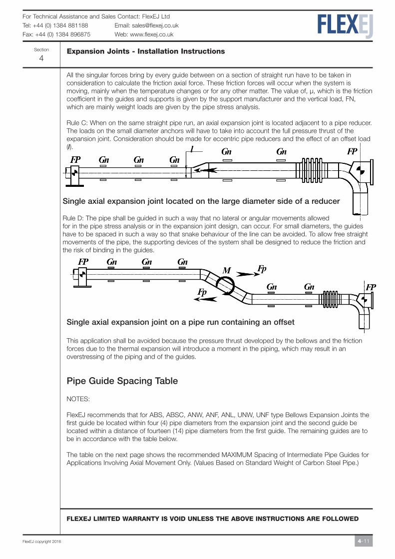
Rule C: When on the same straight pipe run, an axial expansion joint is located adjacent to a pipe reducer.The loads on the small diameter anchors will have to take into account the full pressure thrust of theexpansion joint. Consideration should be made for eccentric pipe reducers and the effect of an offset load(l).
Single axial expansion joint located on the large diameter side of a reducer
Rule D: The pipe shall be guided in such a way that no lateral or angular movements allowed for in the pipe stress analysis or in the expansion joint design, can occur. For small diameters, the guideshave to be spaced in such a way so that snake behaviour of the line can be avoided. To allow free straightmovements of the pipe, the supporting devices of the system shall be designed to reduce the friction andthe risk of binding in the guides.
Single axial expansion joint on a pipe run containing an offset
This application shall be avoided because the pressure thrust developed by the bellows and the frictionforces due to the thermal expansion will introduce a moment in the piping, which may result in anoverstressing of the piping and of the guides.
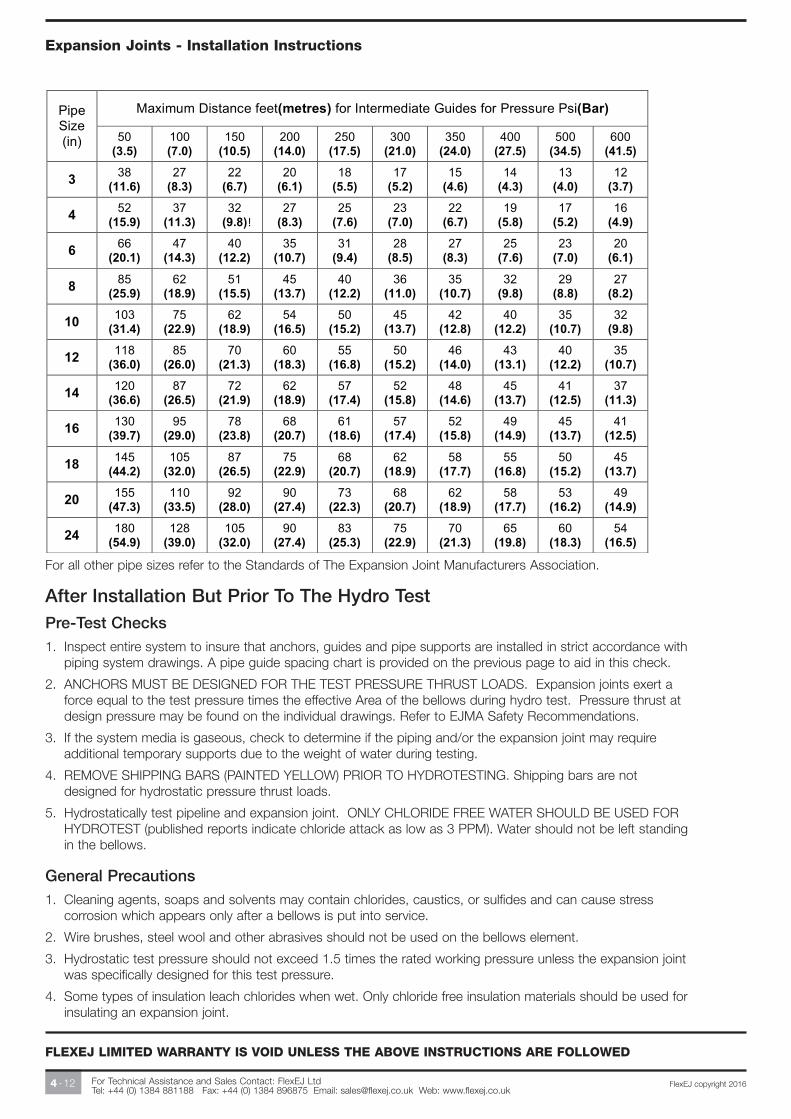
Pipe Guide Spacing Table
NOTES:
FlexEJ recommends that for ABS, ABSC, ANW, ANF, ANL, UNW, UNF type Bellows Expansion Joints thefirst guide be located within four (4) pipe diameters from the expansion joint and the second guide belocated within a distance of fourteen (14) pipe diameters from the first guide. The remaining guides are tobe in accordance with the table below.
The table on the next page shows the recommended MAXIMUM Spacing of Intermediate Pipe Guides forApplications Involving Axial Movement Only. (Values Based on Standard Weight of Carbon Steel Pipe.)
For Technical Assistance and Sales Contact: FlexEJ Ltd Tel: +44 (0) 1384 881188 Fax: +44 (0) 1384 896875 Email: [email protected] Web: www.flexej.co.uk
4 -12 FlexEJ copyright 2016
Expansion Joints - Installation Instructions
FLEXEJ LIMITED WARRANTY IS VOID UNLESS THE ABOVE INSTRUCTIONS ARE FOLLOWED
After Installation But Prior To The Hydro TestPre-Test Checks1. Inspect entire system to insure that anchors, guides and pipe supports are installed in strict accordance with
piping system drawings. A pipe guide spacing chart is provided on the previous page to aid in this check.
2. ANCHORS MUST BE DESIGNED FOR THE TEST PRESSURE THRUST LOADS. Expansion joints exert aforce equal to the test pressure times the effective Area of the bellows during hydro test. Pressure thrust atdesign pressure may be found on the individual drawings. Refer to EJMA Safety Recommendations.
3. If the system media is gaseous, check to determine if the piping and/or the expansion joint may requireadditional temporary supports due to the weight of water during testing.
4. REMOVE SHIPPING BARS (PAINTED YELLOW) PRIOR TO HYDROTESTING. Shipping bars are notdesigned for hydrostatic pressure thrust loads.
5. Hydrostatically test pipeline and expansion joint. ONLY CHLORIDE FREE WATER SHOULD BE USED FORHYDROTEST (published reports indicate chloride attack as low as 3 PPM). Water should not be left standingin the bellows.
General Precautions1. Cleaning agents, soaps and solvents may contain chlorides, caustics, or sulfides and can cause stress
corrosion which appears only after a bellows is put into service.
2. Wire brushes, steel wool and other abrasives should not be used on the bellows element.
3. Hydrostatic test pressure should not exceed 1.5 times the rated working pressure unless the expansion jointwas specifically designed for this test pressure.
4. Some types of insulation leach chlorides when wet. Only chloride free insulation materials should be used forinsulating an expansion joint.
For all other pipe sizes refer to the Standards of The Expansion Joint Manufacturers Association.