practical workbook artificial intelligence & robotics
TRANSCRIPT

Practical Workbook
Artificial Intelligence & Robotics
Name : _____________________________
Year : _____________________________
Batch : _____________________________
Roll No : _____________________________
Department: _____________________________
Third Edition: 2012
Department of Computer & Information Systems Engineering
NED University of Engineering & Technology,
Karachi – 75270, Pakistan

INTRODUCTION The Laboratory Workbook supports the Practical Sessions of the course Artificial Intelligence & Robotics (AI & R). The Workbook has been divided in four sections, each section covering a particular area of Artificial Intelligence.
Each laboratory session begins with a theoretical introduction to the topic under discussion, followed by problem solving methodology and concludes with Exercise problems.
First Section is related to Artificial Neural Networks (ANN), which is a problem solving paradigm, used to solve complex, non-linear problems where conventional algorithm solution is either not possible or not feasible. The section begins with laboratory session on implementation of basic logic function, and is followed by methods of creating and working on ANNs. Next lab session describes problems solving phases of ANNs; and finally the effect of external have been observed on the performance of ANNs.
The second section covers the basic and advanced concepts of developing Expert Systems. The first two laboratory sessions discuss the syntax and usage of Specialization/Generalization definitions of Rules, followed by introduction to the concepts of Data Driven Programming. The Next two laboratory sessions covers the details of knowledge extraction and structures of a typical Expert System.
The third section covers the fundamentals of Parallax Boe-Bot Robot and working of its various components including servo motors, whiskers, infrared LEDs, piezospeaker and phototransistors. The series of hands-on activities and tasks will introduce students to basic robotic concepts.
The fourth section explains how to build Fuzzy Logic based applications using Matlab Fuzzy Logic Toolbox. It also covers another tool Fuzzy Tech for building these applications.

CONTENTS
Lab Session No. Object Page No.
Section One: Artificial Neural Networks
1 Implementation of basic logic operations 2
2 Developing an Artificial Neural Network 9
3 Using ANN for Problem Solving 15
4 Effect of Data Preprocessing on Artificial Neural Networks 20
5 Learning Matlab Neural Networks toolbox for the development of 23
neural network based applications
Section Two: Expert Systems
6 Learning basic concepts of frames and inheritance for Expert System 31
Programming and understanding the anatomy of a Flex Program.
7 Working with Ruleset and defining questions in Flex. 47
8 Learning Data-Driven programming concepts 60
Section Three: Robotics
9 Introducing the Parallax Boe-Bot® robot 66
10 Introducing the Boe-Bot’s Servo Motors 70
11 Implementing the Boe-Bot’s Tactile Navigation with Whiskers 82
12 Navigating the Boe-Bot with Infrared Headlights and Phototransistors 92
Section Four: Fuzzy Logic
13 Learning Matlab Fuzzy Logic toolbox for the development of fuzzy 105
logic based applications
14
Working from the Command Line of Matlab to build fuzzy logic based
application 115
15
Learning FuzzyTech for the development of fuzzy logic based applications. 124

Section One
Artificial Neural Networks
1

Artificial Intelligence & Robotics Lab Session 01 NED University of Engineering & Technology – Department of Computer & Information Systems Engineering
Lab Session 01
OBJECT
Implementation of basic logic operations
Introduction
Artificial Neural Network
An Artificial Neural Network (ANN) is an information processing paradigm that is inspired by the way biological nervous systems, such as the brain, process information. The key element of this paradigm is the novel structure of the information processing system. It is composed of a large number of highly interconnected processing elements (neurons) working in unison to solve specific problems. ANNs, like people, learn by example. An ANN is configured for a specific application, such as pattern recognition or data classification, through a learning process. Learning in biological systems involves adjustments to the synaptic connections that exist between the neurons. This is true of ANNs as well.
Why Use Artificial Neural Networks?
Artificial Neural Networks, with their remarkable ability to derive meaning from complicated or imprecise data, can be used to extract patterns and detect trends that are too complex to be noticed by either humans or other computer techniques. A trained Artificial Neural Network can be thought of as an "expert" in the category of information it has been given to analyze. This expert can then be used to provide projections given new situations of interest and answer "what if" questions. Other advantages include:
1. Adaptive learning: An ability to learn how to do tasks based on the data given for training or initial experience.
2. Self-Organization: An ANN can create its own organization or representation of the information it receives during learning time.
3. Real Time Operation: ANN computations may be carried out in parallel, and special hardware devices are being designed and manufactured which take advantage of this capability.
4. Fault Tolerance via Redundant Information Coding: Partial destruction of a network leads to the corresponding degradation of performance. However, some network capabilities may be retained even with major network damage.
A Simple Neuron
An artificial neuron is a device with many inputs and one output. The neuron has two modes of operation; the training mode and the using mode. In the training mode, the neuron can be trained to fire (or not), for particular input patterns. In the using mode, when a taught input pattern is detected at the input, its associated output becomes the current output. If the input pattern does not belong in the taught list of input patterns, the firing rule is used to determine whether to fire or not.
2

Artificial Intelligence & Robotics Lab Session 01 NED University of Engineering & Technology – Department of Computer & Information Systems Engineering
Figure 1.1: A simple neuron
Network layers
The commonest type of Artificial Neural Network consists of three groups, or layers, of units: a layer of "input" units is connected to a layer of "hidden" units, which is connected to a layer of "output" units. (See figure 1.2) The activity of the input units represents the raw information that is fed into the network. The activity of each hidden unit is determined by the activities of the input units and the
weights on the connections between the input and the hidden units. The behavior of the output units depends on the activity of the hidden units and the eights
between the hidden and output units.
This simple type of network is interesting because the hidden units are free to construct their own representations of the input. The weights between the input and hidden units determine when each hidden unit is active, and so by modifying these weights, a hidden unit can choose what it represents.
Figure 1.2: A Simple Feed Forward Network
We also distinguish single-layer and multi-layer architectures. The single-layer organization, in which all units are connected to one another, constitutes the most general case and is of more potential computational power than hierarchically structured multi-layer organizations. In multi-layer networks, units are often numbered by layer, instead of following a global numbering.
Perceptrons
The most influential work on neural nets in the 60's went under the heading of 'perceptrons' a term coined by Frank Rosenblatt. The perceptron (See figure 1.3) turns out to be an MCP model ( neuron with weighted inputs ) with some additional, fixed, pre-processing. Units labeled A1, A2, Aj , Ap are called association units and their task is to extract specific,
3
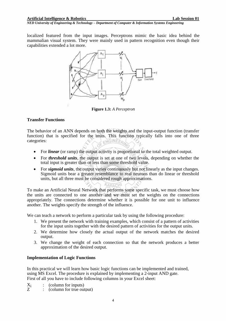
Artificial Intelligence & Robotics Lab Session 01 NED University of Engineering & Technology – Department of Computer & Information Systems Engineering localized featured from the input images. Perceptrons mimic the basic idea behind the mammalian visual system. They were mainly used in pattern recognition even though their capabilities extended a lot more.
Figure 1.3: A Perceptron
Transfer Functions
The behavior of an ANN depends on both the weights and the input-output function (transfer function) that is specified for the units. This function typically falls into one of three categories:
For linear (or ramp) the output activity is proportional to the total weighted output.
For threshold units, the output is set at one of two levels, depending on whether the total input is greater than or less than some threshold value.
For sigmoid units, the output varies continuously but not linearly as the input changes.
Sigmoid units bear a greater resemblance to real neurons than do linear or threshold units, but all three must be considered rough approximations.
To make an Artificial Neural Network that performs some specific task, we must choose how the units are connected to one another and we must set the weights on the connections appropriately. The connections determine whether it is possible for one unit to influence another. The weights specify the strength of the influence.
We can teach a network to perform a particular task by using the following procedure: 1. We present the network with training examples, which consist of a pattern of activities
for the input units together with the desired pattern of activities for the output units. 2. We determine how closely the actual output of the network matches the desired
output. 3. We change the weight of each connection so that the network produces a better
approximation of the desired output.
Implementation of Logic Functions
In this practical we will learn how basic logic functions can be implemented and trained, using MS Excel. The procedure is explained by implementing a 2-input AND gate. First of all you have to include following columns in your Excel sheet:
Xi : (column for inputs) Z : (column for true output)
4
Artificial Intelligence & Robotics Lab Session 01 NED University of Engineering & Technology – Department of Computer & Information Systems Engineering
Y : (column for computed output)
D : (column for keeping track of the difference between true output & computed one)
Wi : (column for initial weights, assigned arbitrarily in the first step) Wf : (column for final weights, which is computed from initial weight and becomes the initial weight of the first step)
Procedure
1. In input columns X1 and X2, include all possible values which can be provided to a
2-input AND gate, and in column Z, list all expected results.
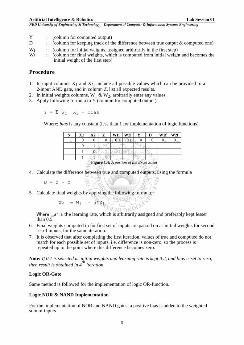
2. In initial weights columns, W1 & W2, arbitrarily enter any values. 3. Apply following formula to Y (column for computed output);
Y = Wi Xi + bias
Where; bias is any constant (less than 1 for implementation of logic functions).
S X1 X2 Z W1i W2i Y D W1f W2f
1 0 0 0 0.1 0.1 0 0 0.1 0.1
0 1 1
1 0 1
1 1 1 Figure 1.4: A portion of the Excel Sheet
4. Calculate the difference between true and computed outputs, using the formula
D = Z – Y 5. Calculate final weights by applying the following formula.
Wf = Wi + aDXi
Where ‗a‘ is the learning rate, which is arbitrarily assigned and preferably kept lesser than 0.5
6. Final weights computed in for first set of inputs are passed on as initial weights for second set of inputs, for the same iteration.
7. It is observed that after completing the first iteration, values of true and computed do not match for each possible set of inputs, i.e. difference is non-zero, so the process is repeated up to the point where this difference becomes zero.
Note: If 0.1 is selected as initial weights and learning rate is kept 0.2, and bias is set to zero,
then result is obtained in 4th
iteration. Logic OR-Gate Same method is followed for the implementation of logic OR-function. Logic NOR & NAND Implementation
For the implementation of NOR and NAND gates, a positive bias is added to the weighted sum of inputs.
5

Artificial Intelligence & Robotics Lab Session 01 NED University of Engineering & Technology – Department of Computer & Information Systems Engineering
EXERCISES
1. Complete the following
tables. a. Operation Weights Learning Iterations
Rate Required
W1 W2
0.1 0.1 0.2
OR
0.9 0.8 0.2
0.5 0.5 0.2
0.2 0.4 0.2
-0.3 -0.5 0.2
b.
Operation Weights Learning Iterations
W1 W2 Rate Required
0.9 0.9 0.2
AND
0.1 0.1 0.2
0.5 0.5 0.2
0.9 0.7 0.2
-0.7 -0.8 0.4
c. Operation Weights Learning Bias Iterations
Rate Required
W1 W2
0.3 0.4 0.2 0.9
NAND 0.9 0.9 0.2 0.7
0.8 0.6 0.2 0.9
0.9 0.7 0.2 0.2
-0.7 -0.8 0.4 0.8
d. Operation Weights Learning Bias Iterations
Rate Required
W1 W2
0.2 0.4 0.2 0.8
NOR 0.8 0.9 0.2 0.8
0.8 0.9 0.2 0.9
0.8 0.9 0.2 0.6
0.3 0.4 0.4 0.6
2. For NAND and NOR implementation, what is the effect of setting bias to value <0.5?
_______________________________________________________________________
3. Add a positive bias <0.3 to AND and OR gate‘s output and check how many iterations are
required to get correct output. ________________________________________________________________________
4. What are your observations, regarding the following?
a. Lower value of learning rate is faster. (Yes/No)
Reason: _________________________________________________________________
________________________________________________________________________
6

Artificial Intelligence & Robotics Lab Session 01 NED University of Engineering & Technology – Department of Computer & Information Systems Engineering
b. For OR gate implementation, smaller values of weights require less iterations for obtaining correct result. (Yes/No)
Reason: _________________________________________________________________
________________________________________________________________________
c. For NAND gate implementation, larger values of weights require less iterations for
obtaining correct result. (Yes/No) Reason: _________________________________________________________________
________________________________________________________________________
5. Implement XOR and XNOR functions and give all the formula you used in the
implementation. Draw the MLPs used for the implementation of above functions. Also mention the following:
6. XOR XNOR
Learning rate
Initial weights
Bias
Iterations required
Attach the Excel Sheet here.
7

Artificial Intelligence & Robotics Lab Session 01 NED University of Engineering & Technology – Department of Computer & Information Systems Engineering
7. Implement 3-input AND, OR, NAND and NOR gates. Attach Excel Sheets here.
8

Artificial Intelligence & Robotics Lab Session 02 NED University of Engineering & Technology – Department of Computer & Information Systems Engineering
Lab Session 02
OBJECT
Developing an Artificial Neural Network
Introduction
EasyNN EasyNN can be used to create, control, train, validate and query neural networks. Getting Started
In order to create a neural network, press the New toolbar button or use the File>New menu command to produce a new neural network,
An empty Grid with a vertical line, a horizontal line and an underline marker will appear. The marker shows the position where a grid column and row will be produced. Press the enter key and you will be asked "Create new Example row?" - answer Yes.
You will then be asked "Create new Input/Output column?" - answer Yes.
You have now created a training example with one input. The example has no name and no value. Press the enter key again and you will open the Edit dialog (see figure 2.1). This dialog is used to enter or edit all of the information in the Grid.
Figure 2.1: Edit Dialog
Enter value, in the Value + Norm edit box and then tab. Type input name in the Example Name + Type edit box and then tab. The Type is already set to Training so just tab again. By following above procedure, you can enter training data.
To create the neural network press the toolbar button or use the Action>New
Network menu command. This will open the ‗New Network‘ dialog. (See figure 2.2)
9

Artificial Intelligence & Robotics Lab Session 02 NED University of Engineering & Technology – Department of Computer & Information Systems Engineering
Figure 2.2: New Network Dialog The neural network will be produced from the data you entered into the grid.
Press the toolbar button or use the View>Network menu command to see the new
neural network. This network will be somewhat like what is shown in figure 2.3
Figure 2.3: Artificial Neural Network
The neural network controls now need to be set. Press toolbar button or sue
Action>Change Controls menu command to open the Controls dialog. Check
Optimize for both Learning Rate and Momentum and then press Ok. In this way,
controls can be set and the neural network will be ready to learn the data that you entered into
the grid. (See figure 2.4)
Press toolbar button or use the Action>Start Learning menu command to open
the Learning Progress dialog. The learning process will start and it will stop
automatically, when the target error is reached. Press the Close button.
Press toolbar button or use the View>Graph menu command to see how the error
reduced to the target.
10

Artificial Intelligence & Robotics Lab Session 02 NED University of Engineering & Technology – Department of Computer & Information Systems Engineering
Figure 2.4: Controls Dialog
Press toolbar button or use the Action>Query menu command to open the Query dialog.
Press the Add Query button and the example named ―Query‖ will be generated and
selected. Values for Query can be inserted here and output can be observed (See figure 2.5)
Figure 2.5: Query Dialog
Importing a File Up till now, we have learned that how an artificial neural network can be grown and trained using EasyNN. Now we‘ll cover how real world data file, collected through different sources can be imported in EasyNN for neural network training.
Procedure
EasyNN can import a text file to create a new Grid or to add new example rows to an existing Grid in the following manner.
11

Artificial Intelligence & Robotics Lab Session 02 NED University of Engineering & Technology – Department of Computer & Information Systems Engineering
1. File>New to create a new Grid or File>Open to add rows to an existing Grid.
2. File > Import File 3. Open the file that is to be imported.
Figure 2.6 4. Check all the characters that are to be used for column delimiters. 5. Any words before the first delimiter on each line can be used for row names. If no row
names are available then EasyNN can generate numbers for row names. 6. Press OK.
Figure 2.7
7. Press Next line until the first line to be imported is shown.
8. Press Use line or Set names according to the instructions in the dialog.
Figure 2.8
12

Artificial Intelligence & Robotics Lab Session 02 NED University of Engineering & Technology – Department of Computer & Information Systems Engineering
9. Set the column types when the first line is imported.
10. Press OK. 11. The rest of the file will be imported (See figure 2.9). Warnings will be produced for any lines in the file that are not suitable for the Grid.
Figure 2.9 Note: Network is grown and trained in the same manner as previously discussed.
EXERCISES
1. Create a neural network, by using the training data, presented in the table. And test it on
the given queries.
Red Green Blue Cyan Magenta Yellow Output Output Type
1 1 0 0 0 1 Y 0 Training
1 0 1 0 1 0 M 0.5 Training
0 1 1 1 0 0 C 1 Training
0.9 0.9 0.3 Querying
0.6 0.6 0.4 Querying
0.5 0.5 0.5 Querying
0 0 0 Querying
1 1 1 Querying
0.8 0.2 0.7 Querying
Learning rate selected: __________
Stop when average error is: __________
13

Artificial Intelligence & Robotics Lab Session 02 NED University of Engineering & Technology – Department of Computer & Information Systems Engineering
(a) Multiple output lines give better results. (Yes/ No) Reason:
___________________________________________________________________________
_________________________________________
_________________________________________
2. Import a data file, provided by the instructor, grow an Artificial Neural Network, train it and test on different queries. 3. Give the following specification of your network. (a) Learning rate selected : __________
(b) Stop when average error is: __________
(c) Inputs to the system and their type:
__________________________________________________
__________________________________________________
__________________________________________________
__________________________________________________
__________________________________________________
__________________________________________________
__________________________________________________
__________________________________________________
__________________________________________________
__________________________________________________
(d) Number of outputs and their types
__________________________________________________
__________________________________________________
__________________________________________________
__________________________________________________
__________________________________________________
__________________________________________________
14
Artificial Intelligence & Robotics Lab Session 03 NED University of Engineering & Technology – Department of Computer & Information Systems Engineering
Lab Session 03
OBJECT
Using ANN for Problem Solving
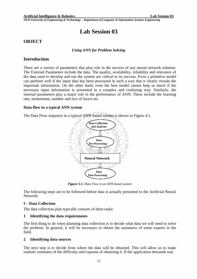
Introduction There are a variety of parameters that play role in the success of any neural network solution. The External Parameters include the data. The quality, availability, reliability and relevance of the data used to develop and run the system are critical to its success. Even a primitive model can perform well if the input data has been processed in such a way that it clearly reveals the important information. On the other hand, even the best model cannot help us much if the necessary input information is presented in a complex and confusing way. Similarly, the internal parameters play a major role in the performance of ANN. These include the learning rate, momentum, number and size of layers etc. Data-flow in a typical ANN system The Data Flow sequence in a typical ANN-based system is shown in Figure 4.1.
Data Collection and Analysis
Data Pre-Processing
Neural Network
Data
Post-Processing
Figure 3.1: Data Flow in an ANN-based system
The following steps are to be followed before data is actually presented to the Artificial Neural Network: I – Data Collection The data collection plan typically consists of three tasks: 1 Identifying the data requirements The first thing to do when planning data collection is to decide what data we will need to solve the problem. In general, it will be necessary to obtain the assistance of some experts in the field. 2 Identifying data sources The next step is to decide from where the data will be obtained. This will allow us to make realistic estimates of the difficulty and expense of obtaining it. If the application demands real
15

Artificial Intelligence & Robotics Lab Session 03 NED University of Engineering & Technology – Department of Computer & Information Systems Engineering time data, these estimates should include an allowance for converting analogue data to digital form. 3 Determining the data quantity It is important to make a reasonable estimation of how much data we will need to develop the neural network properly. If too little data is collected, it may not reflect the full range of properties that the network should be learning, and this will limit its performance with unseen data. On the other hand, it is possible to introduce unnecessary expense by collecting too much data. In general, the quantity of data required is governed by the number of training cases that will be needed to ensure the network performs adequately. II – Data Preparation When the raw data has been collected, it may need converting into a more suitable format. At this stage, we should do the following: 1 Data validity checks Data validity checks will reveal any patently unacceptable data that, if retained, would produce poor results. A simple data range check is an example of validity checking. For example, if we have collected oven temperature data in degrees centigrade, we would expect
values in the range 50 oC to 400
oC. A value of, say, -10
oC, or 900
oC, is clearly wrong.
2 Partitioning data Partitioning is the process of dividing the data into validation sets, training sets, and test sets. By definition, validation sets are used to decide the architecture of the network; training sets are used to actually update the weights in a network; test sets are used to examine the final performance of the network. The primary concerns should be to ensure that: a) the training set contains enough data, and suitable data distribution to adequately demonstrate the properties we wish the network to learn; b) there is no unwarranted similarity between data in different data sets. III – Data Preprocessing Data preprocessing consists of all the actions taken before the Neural Network comes into play. It is essentially a transformation T that transforms the raw real world data vectors X to a set of new data vectors Y:
Y = T (X)
such that: i. Y preserves the ―valuable information‖ in X and ii. Y is more useful than X. IV – Training the ANN This involves the following steps:
1. Transfer Data from Spreadsheet (E.g. MS - Excel) to ANN Tool (E.g. EasyNN)
2. Grow a Neural Network
3. Set Controls (optional) 4. Start Training
5. View Results
16

Artificial Intelligence & Robotics Lab Session 03 NED University of Engineering & Technology – Department of Computer & Information Systems Engineering
V – Querying the ANN Querying the Network involves the following steps:
1. Transfer data from Spreadsheet to Tool
2. Query the Network
3. View Results
Practical ANN-based Systems Artificial Neural Networks are being used in various application domains, like prediction, classification, diagnosis and forecasting etc in different situations like Stock Rate prediction, weather forecasting, Pattern Recognition and Medical Applications etc.
An ANN based Heart Disease Diagnosis System
The case study has been taken up to diagnose the presence or absence of Heart Disease in clients. As mentioned above, there are certain steps that are to be considered before ANN comes into play. As mentioned above, these steps include: Data Collection – A database of 75 attributes has been constructed for HDDS. After thorough analysis, irrelevant and redundant parameters have been removed. The final database comprises of 13 parameters, on the basis of which, the output is computed. These are: i. Age (Real Number)
ii. Gender (Binary)
iii. Chest pain type (4 values) (Real Number)
iv. Resting blood pressure (Real Number) v. Serum cholesterol in mg/dl (Real Number)
vi. Fasting blood sugar > 120 mg/dl (Binary)
vii. Resting electrocardiographic results (values 0,1,2) (Real Number)
viii. Maximum heart rate achieved (Real Number)
ix. Exercise induced angina (Binary)
x. Oldpeak = ST depression induced by exercise relative to rest (Real Number)
xi. The slope of the peak exercise ST segment (Real Number)
xii. Number of major vessels (0-3) colored by flourosopy (Ordered)
xiii. Thal: 3 = normal; 6 = fixed defect; 7 = reversable defect (Real Number) The output of the system is either absence or presence of Heart Disease (represented by 1 and 2 respectively). A total of 270 cases have been considered. Out of these cases, 55.56% showed an absence of disease and 44.44% showed presence of disease. It has been ensured that the dataset contains nearly equal percentage of both the classes of output. A portion of the dataset is given here:
44 0 3 108 141 0 0 175 0 0.6 2 0 3 1
71 0 4 112 149 0 0 125 0 1.6 2 0 3 1
45 0 2 112 160 0 0 138 0 0 2 0 3 1
57 1 3 150 168 0 0 174 0 1.6 1 0 3 1
65 1 4 120 177 0 0 140 0 0.4 1 0 7 1
46 0 3 142 177 0 2 160 1 1.4 3 0 3 1
17

Artificial Intelligence & Robotics Lab Session 03 NED University of Engineering & Technology – Department of Computer & Information Systems Engineering
77 1 4 125 304 0 2 162 1 0 1 3 3 2
56 0 4 200 288 1 2 133 1 4 3 2 7 2
67 1 4 120 237 0 0 71 0 1 2 0 3 2
54 1 2 192 283 0 2 195 0 0 1 1 7 2
62 0 4 160 164 0 2 145 0 6.2 3 3 7 2
67 1 4 160 286 0 2 108 1 1.5 2 3 3 2
There are some companies that collect and provide such statistical data, which may be used in Neural network based applications. Data Preparation This step involves Validity checking and Partitioning of Data. The data has been partitioned into two parts – The training dataset and the test dataset. It has been ensured that the minimum and maximum value of each parameter lies in the training dataset because the ANN generates a working range for each parameter and values outside this range are clipped off. Data Preprocessing The data has been preprocessed using the scaling technique, and then used to train the ANN. The sample scaled data is shown here: 0.3125 0 0.666667 0.13207 0.03424 0 0 0.793893 0 0.09677 0.5 0 0 1
0.875 0 1 0.16981 0.05251 0 0 0.412213 0 0.25806 0.5 0 0 1
0.33333 0 0.333333 0.16981 0.07762 0 0 0.511450 0 0 0.5 0 0 1
0.58333 1 0.666667 0.52830 0.09589 0 0 0.786259 0 0.25806 0 0 0 1 0.75 1 1 0.24528 0.11643 0 0 0.526717 0 0.06451 0 0 1 1
0.35416 0 0.666667 0.45283 0.11643 0 1 0.679389 1 0.22580 1 0 0 1
0.5625 0 1 0.37735 0.64611 0 1 0.603053 1 0.30645 0.5 0.6667 1 2
1 1 1 0.29245 0.40639 0 1 0.694656 1 0 0 1 0 2
0.5625 0 1 1 0.36986 1 1 0.473282 1 0.64516 1 0.6667 1 2 0.79166 1 1 0.24528 0.25342 0 0 0 0 0.16129 0.5 0 0 2
0.52083 1 0.333333 0.92452 0.35844 0 1 0.946564 0 0 0 0.3333 1 2
0.6875 0 1 0.62264 0.08675 0 1 0.564885 0 1 1 1 1 2 Training the ANN 1. Training involves importing the ‗train dataset‘ for HDDS in the tool. 2. The Neural Network is then generated and various parameters are defined, along with the
terminating criterion. 3. The training begins once the controls are set and is terminated once the criterion is met. Testing the ANN Once training is complete, the HDDS is tested for authenticity. This may be accomplished by either inserting the queries manually or by importing the ‗HDDS test dataset‘ into the tool. On the basis of training, the ANN based HDDS predicts the presence or absence of Heart Disease in patients.
18

Artificial Intelligence & Robotics Lab Session 03 NED University of Engineering & Technology – Department of Computer & Information Systems Engineering
EXERCISES
1. Come up with some Real-world problem, generate and train an ANN for it and then query the network. Mention the Input and Output parameters.
__________________________________________________
__________________________________________________
__________________________________________________
__________________________________________________
__________________________________________________
__________________________________________________
__________________________________________________
__________________________________________________
__________________________________________________
__________________________________________________
__________________________________________________
__________________________________________________
__________________________________________________
__________________________________________________
2. In continuation with Exercise 1 fill in the following entries: Number of Output Categories: __________________________________________
Number of Data Rows: __________________________________________
Number of Training Rows: __________________________________________
Number of Testing Rows: __________________________________________
Learning Rate: __________________________________________
Momentum: __________________________________________
Number of Layers: __________________________________________
Size of Layers:
________________________________________________________________________
________________________________________________________________________ ________________________________________________________________________
________________________________________________________________________
Number of Cycles for Training: __________________________________________
Percentage of Correctness in Results: __________________________________________
19

Artificial Intelligence & Robotics Lab Session 04 NED University of Engineering & Technology – Department of Computer & Information Systems Engineering
Lab Session 04
OBJECT
Effect of Data Preprocessing on Artificial Neural Networks
Introduction
Data preprocessing consists of all the actions taken before the Neural Network comes into play. It is essentially a transformation T that transforms the raw real world data vectors X to a set of new data vectors Y:
Y = T (X) such that:
i. Y preserves the ―valuable information‖ in X and ii. Y is more useful than X.
Role/Need of Data Preprocessing
A major component to successfully train a Neural Network is to appropriately represent or encode the inputs and outputs. Artificial Neural Networks only deal with numeric input data. Therefore, the raw data must often be converted from the external environment. Additionally, it is usually necessary to scale the data, or normalize it to the network's paradigm. Many conditioning techniques, which directly apply to Artificial Neural Network implementations, are readily available. It is then up to the network designer to find the best data format and matching network architecture for a given application.
Data preprocessing may be necessary, when it is required to deal with:
i. Missing values
ii. Feature selection and extraction
iii. Large number of categories
iv. Bias in class proportions
v. Hierarchical attributes
vi. Collection of datasets
Different Preprocessing Techniques The preprocessing assignment is distributed as follows:
i. Scaling
ii. Manipulation
iii. Detrending
iv. Smoothing
v. Normalization
vi. Fuzzification Scaling
It is a natural tendency that data in a particular input range seems to be most effective. Data should be chosen to fit a range that does not saturate, or overwhelm the network neurons. Choosing inputs from –1 to 1 or 0 to1 is a good idea.
20

Artificial Intelligence & Robotics Lab Session 04 NED University of Engineering & Technology – Department of Computer & Information Systems Engineering
Linear scaling of input data (logistic 0 to 1)
Input data is usually scaled from 0 to 1. Suppose that the input data range is from 4(min) to 8(max); it could be scaled from 0(min) to 1(max). Hence 4 becomes 0 and 8 becomes 1. For all values: temp_value = (raw - minimum_raw)/(maximum_raw - minimum_raw) For example, if raw value = 6 temp value = (6-4)/(8-4) = 2/4 = 0.5
Note that temp_value is the scaled value if we wish to scale the input data in between 0 and 1. It could be useful for the output data to be scaled between any two limits (say hyperbolic tangent -1 to +1). As per activation function, it would require a net input of infinity to get an output of 1. Hence the data is often scaled to values that are easier to achieve. eg
scaling between -0.9 and +0.9 scaled_val=(scaled_max - scaled_min) * temp_val + scaled_min scaled_val = (0.9 -(-0.9)) * 0.5 + (-0.9) = (1.8)*0.5 - 0.9 = 0 Detrending
Detrending involves removing the mean values or linear trends from the data. The zero-order trend of a set of measured values, or data points, is the mean. Smoothing
It may be required to de-emphasize unwanted noise in the input data. Data smoothing techniques are used to eliminate "noise" and extract real trends and patterns. There are a variety of smoothing techniques that may be applied on the basis of presence or absence of trends and/or cycle in the data. The most common smoothing technique is Moving Average that may be calculated using the following formula:
k-1
y/k = 1 yj
Normalization Data sets can exhibit large dynamic variances over one or more dimensions in the data. These large variances can often dominate more important but smaller trends in the data. One technique for removing these variations is normalization. Normalization removes redundant information from a data set, typically by compacting it or making it invariant over one or more features. normalized_value = (raw - average)/(maximum_raw - minimum_raw)
21

Artificial Intelligence & Robotics Lab Session 04 NED University of Engineering & Technology – Department of Computer & Information Systems Engineering
Fuzzification
To make the data more suitable for training a neural net, fuzzification can be used. The process of ―fuzzification‖ may be regarded as a methodology to generalize any specific theory from a crisp (discrete) to a continuous (fuzzy) form. It is a means of dealing with information presented in imprecise terms. It is built around the concept of reasoning in degrees, rather than in absolute black-and-white terms.
EXERCISES 1. Continue with the same Real-world problem as in previous lab session. Fill the following table.
Preprocessing Number Maximum Average Minimum Query Result
Applied of cycles Error Error Error
Correct % out of __ correctness
Original Data (No
Preprocessing Applied)
Smoothing: (n = 2)
Scaling i/p data
2. Mention your observation whether Data Preprocessing has a positive/negative/no effect on ANN in your system.
__________________________________________________
__________________________________________________
__________________________________________________
__________________________________________________
22

Artificial Intelligence & Robotics Lab Session 05 NED University of Engineering & Technology – Department of Computer & Information Systems Engineering
Lab Session 05
OBJECT
Learning Matlab Neural Networks toolbox for the development of neural network
based applications
Basics
Neural networks are composed of simple elements operating in parallel. These elements are
inspired by biological nervous systems. As in nature, the connections between elements
largely determine the network function. You can train a neural network to perform a
particular function by adjusting the values of the connections (weights) between elements.
Typically, neural networks are adjusted, or trained, so that a particular input leads to a
specific target output. This lab session gives you an insight of training a neural network to fit
a function using Neural Network Toolbox functions.
We will first create a perceptron network to perform the operation of AND function for two variables.
To start, type nntool. The following window appears. (See fig. 5.1)
Fig 5.1
First, define the network input, called p, having the value [0 0 1 1;0 1 0 1]. Thus, the network has a two-element input, and four sets of such two-element vectors are presented to it in training. To define this data, click New, and a new window, Create Network or Data,
appears (see fig 5.2). Select the Data tab. Set the Name to p, the Value to [0 0 1 1; 0 1
0 1], and set Data Type to Inputs.
23

Artificial Intelligence & Robotics Lab Session 05 NED University of Engineering & Technology – Department of Computer & Information Systems Engineering
Fig 5.2
Click Create and then click OK to create an input p. The Network/Data Manager window
appears, and p shows as an input. Next create a network target. This time enter the variable
name t, specify the value [0 0 0 1], and click Targets under Data Type. Again click Create and OK. You will see in the resulting Network/Data Manager window that you now
have t as a target as well as the previous p as an input.
In order to create a new network ANDNet, select the Network tab. Enter ANDNet under Name. Set the Network Type to Perceptron, for that is the kind of network you want to
create. You can set the inputs to p, and the example targets to t. You can use a hardlim
transfer function with the output range [0, 1] that matches the target values and a learnp
learning function. For the Transfer function, select hardlim. For the Learning function,
select learnp.
The Create Network or Data window now looks like the following figure(see fig 5.3).
24

Artificial Intelligence & Robotics Lab Session 05 NED University of Engineering & Technology – Department of Computer & Information Systems Engineering
Fig 5.3
Now click Create and OK to generate the network. Now close the Create Network or Data window. To train the network, click ANDNet to highlight it (see fig 5.4).
Fig 5.4
25

Artificial Intelligence & Robotics Lab Session 05 NED University of Engineering & Technology – Department of Computer & Information Systems Engineering Then double click to Open. This leads to a new window, labeled Network: ANDNet. (see Fig 5.5)
Fig 5.5
At this point you can see the network again by clicking the View tab. You can also check on the initialization by clicking the Initialize tab. Now click the Train tab. Specify the inputs
and output by clicking the Training Info tab and selecting p from the list of inputs and t from the list of targets. The Network: ANDNet window should look like fig 5.6.
Fig 5.6
26
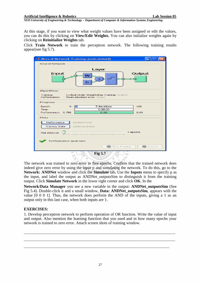
Artificial Intelligence & Robotics Lab Session 05 NED University of Engineering & Technology – Department of Computer & Information Systems Engineering At this stage, if you want to view what weight values have been assigned or edit the values, you can do this by clicking on View/Edit Weights. You can also initialize weights again by clicking on Reinitialize Weights tab. Click Train Network to train the perceptron network. The following training results appear(see fig 5.7).
Fig 5.7
The network was trained to zero error in five epochs. Confirm that the trained network does indeed give zero error by using the input p and simulating the network. To do this, go to the Network: ANDNet window and click the Simulate tab. Use the Inputs menu to specify p as the input, and label the output as ANDNet_outputsSim to distinguish it from the training output. Click Simulate Network in the lower right corner and click OK. In the Network/Data Manager you see a new variable in the output: ANDNet_outputsSim (See Fig 5.4). Double-click it and a small window, Data: ANDNet_outputsSim, appears with the value [0 0 0 1]. Thus, the network does perform the AND of the inputs, giving a 1 as an output only in this last case, when both inputs are 1.
EXERCISES: 1. Develop perceptron network to perform operation of OR function. Write the value of input and output. Also mention the learning function that you used and in how many epochs your network is trained to zero error. Attach screen shots of training window.
___________________________________________________________________________ ___________________________________________________________________________ ________________________________________________________________________
27

Artificial Intelligence & Robotics Lab Session 05 NED University of Engineering & Technology – Department of Computer & Information Systems Engineering 2. Develop perceptron network to implement XOR function. Attach screen shot of training window and state in what respects, implementation of XOR is different from OR function.
___________________________________________________________________________ ___________________________________________________________________________ ___________________________________________________________________________ ___________________________________________________________________________ ___________________________________________________________________________ ___________________________________________________________________________ ___________________________________________________________________________ ___________________________________________________________________________ ___________________________________________________________________________ ___________________________________________________________________________ ___________________________________________________________________________ ___________________________________________________________________________ ___________________________________________________________________________ ___________________________________________________________________________ ___________________________________________________________________________ ___________________________________________________________________________ ___________________________________________________________________________ ___________________________________________________________________________ ___________________________________________________________________________ ___________________________________________________________________________ ___________________________________________________________________________ ___________________________________________________________________________ ___________________________________________________________________________ ___________________________________________________________________________
28

Artificial Intelligence & Robotics Lab Session 05 NED University of Engineering & Technology – Department of Computer & Information Systems Engineering Attach snap shots here.
29

Section Two
Expert Systems
30

Artificial Intelligence & Robotics Lab Session 06 NED University of Engineering & Technology – Department of Computer & Information Systems Engineering
Lab Session 06
OBJECT
Learning basic concepts of frames and inheritance for Expert System Programming
Introduction
flex
flex is an expressive and powerful expert system toolkit which supports frame-based reasoning with inheritance, rule-based programming and data-driven procedures fully integrated within a logic programming environment, and contains its own English-like Knowledge Specification Language (KSL). flex goes beyond most expert system shells in that it employs an open architecture and allows you to access, augment and modify its behavior through a layer of access functions. Because of this, flex is often referred to as an AI toolkit. The combination of flex and Prolog i.e. a hybrid expert system toolkit with a powerful general-purpose AI programming language, results in a functionally rich and versatile expert system development environment where the developers can fine tune and enhance the built-in behavior mechanisms that suits their own specific requirements. flex appeals to various groups of developers; expert systems developers who want to deliver readable and maintainable knowledge-bases, advanced expert system builders who want to incorporate their own controls, AI programmers who want access to a high-level language-based product and Prolog programmers who require extra functionality and structures. Expert Systems
Expert systems (or knowledge-based systems) allow the scarce and expensive knowledge of experts to be explicitly stored into computer programs and made available to others who may be less experienced. They range in scale from simple rule-based systems with flat data to very large scale, integrated developments taking many person-years to develop. They typically
have a set of if-then rules which forms the knowledge base, and a dedicated inference
engine, which provides the execution mechanism. This contrasts with conventional programs where domain knowledge and execution control are closely intertwined such that the knowledge is implicitly stored in the program. This explicit separation of the knowledge from the control mechanism makes it easier to examine knowledge, incorporate new knowledge and modify existing knowledge. Forward Chaining
Forward chaining production rules in flex follow the classical if-then rule format. Forward
chaining is data-driven and is very suitable for problems which involve too many possible outcomes to check by backward chaining, or where the final outcome is not known. The forward chaining inference engine cycles through the current rule agenda looking for rules whose if conditions can be satisfied, and selects a rule to use or fire by executing its then
part. This typically side affects data values, which means that a different set of rules now have their conditions satisfiable.
31
Artificial Intelligence & Robotics Lab Session 06 NED University of Engineering & Technology – Department of Computer & Information Systems Engineering Flex extends the classical production rule with an optional explanation facility and dynamic scoring mechanism for resolving conflicts during rule selection. Rules can have multiple conclusions or actions (either positive or negative) in their then part. The rule selection and agenda update algorithms of the forward chaining engine are flexible, with many built-in algorithms and the option of applying user-defined algorithms. Backward Chaining
Backward chaining rules, which correspond closely to Prolog predicates, are called relations in flex. They have a single conclusion that is true, if all the conditions can be proven. Backward chaining is often referred to as goal-driven, and is closely linked to the notion of provability. Search
Search is one of the key characteristics of expert systems. There are normally many ways of combining or chaining rules together with data to infer new conclusions. How to examine only the relevant part of this search space is a serious consideration with regard to efficiency. The ordering of rules, the provision of meta-rules (rules about which rules to use) and conflict-resolution schemes are all ways of helping us produce a sensible search tree which we can investigate. Prolog-based systems tend to use a depth-first strategy, whereby a certain path is fully explored by checking related paths, combined with backtracking to go back and explore other possibilities when a dead-end is reached. Frames and Inheritance
Frame hierarchies are similar to object-oriented hierarchies. They allow data to be stored in an abstract manner within a nested hierarchy with common properties automatically inherited through the hierarchy. This avoids the unnecessary duplication of information, simplifies code and provides a more readable and maintainable system. Each frame or instance has a set of slots that contain attributes describing the frame's characteristics. These slots are analogous to fields within records (using database terminology) except that their expressive power is greatly extended. Frames inherit attribute-values from other frames according to their position in the frame hierarchy. This inheritance of characteristics is automatic, but can be controlled using different built-in algorithms.
Questions and Answers
Flex has a built-in question and answer sub-system that allows final applications to query the user for additional input via interactive dialogs. These screens can be simple pre-defined ones, or complex, sophisticated screens constructed using Prolog's own screen handling facilities and then attached to the question and answer sub-system. Explanations
Flex has a built-in explanation system which supports both how and why explanations. Explanations can be attached to both rules and questions using simple because clauses.
32

Artificial Intelligence & Robotics Lab Session 06 NED University of Engineering & Technology – Department of Computer & Information Systems Engineering
Data-driven Programming
Flex offers special procedures which can be attached to collections of frames, individual frames or slots within frames. These procedures remain dormant until activated by the accessing or updating of the particular structure to which they have been attached. There are four different types of data-driven procedures available within flex: launches, demons,
watchdogs, and constraints. Knowledge Specification Language
Flex has its own expressive English-like Knowledge Specification Language (KSL) for defining rules, frames and procedures. The KSL enables developers to write simple and concise statements about the expert's world and produce virtually self-documenting knowledge-bases which can be understood and maintained by non-programmers. The KSL supports mathematical, Boolean and conditional expressions and functions along with set abstractions; furthermore, the KSL is extendable through synonyms and templates. By supporting both logical and global variables in rules, flex avoids unnecessary rule duplication and requires fewer rules than most other expert systems. How to Start To start working in flex, you have to type the following in the console window. ensure_loaded(system(flexenv)). Frames and Inheritance
In this chapter we describe the frame sub-system of flex. This includes the form and content of individual frames, how frames are linked together to form a frame hierarchy, and how values are inherited through that hierarchy. What is a Frame?
A frame is similar to an object and is a complex data structure which provides a useful way of modeling real-world data objects.
Frames are analogous to records within a database but are far more powerful and expressive. Each individual frame has a name by which it is referred, details of its parent(s) frame, and a collection of slots or attributes (similar to fields within records) which will contain values or pointers to values. Slot values can be explicitly defined locally, or implicitly inherited from an ancestor frame further up the hierarchy.
Figure 6.1
Flex has its own language (for representing frames and other constructs) called the Knowledge Specification Language. For example, the KSL code for the above frame could be:
33

Artificial Intelligence & Robotics Lab Session 06 NED University of Engineering & Technology – Department of Computer & Information Systems Engineering
frame bird
default skin is feather and
default habitat is a tree and
default motions are { fly } .
Each slot has three principal components:
attribute name - such as habitat, describing the concept
default value - the default value, to be used when there is no current value
current value - the current value for the attribute
Figure 6.2
A frame can be viewed as a dynamic array having three columns (Attribute Name, Default Value and Current Value) and an arbitrary number of rows, one for each slot. It is important to note the difference between default and current values, since some flex operations work on only on current values. The following example is an illustration of a frame representing the concept of a jug.
Figure 6.3
Slots may or may not have values. For example, there is a current but not a default value for
the position of the jug, a default but not a current value for the capacity of the jug, and both a default and a current value for the contents of the jug. The default value for a slot is used only in the absence of a current value for that slot. When a frame is declared in the KSL, the initial default values of its attributes may be declared, as in the above example of the frame bird. However, additional slots may be added dynamically simply by referring to them and giving them a value. For example, the above jug frame may be declared in KSL as: frame jug
default capacity is 15 and default contents is 0.
Its position slot may then be created and its contents updated as follows, using a KSL action (described later). action jug_update ;
do the contents of the jug becomes 7.5 and the position of the jug becomes upright.
34

Artificial Intelligence & Robotics Lab Session 06 NED University of Engineering & Technology – Department of Computer & Information Systems Engineering There are no restrictions on what terms can be used as the default or current values of slots. They can be any valid Prolog term. They can be calculations (or access functions), which are performed whenever you need the slotvalue. frame box
default width is 10 and default depth is 5 and default volume is its width times its depth .
Linking Frames Frames can be linked to each other, it enables a frame hierarchy to be established. Let us consider a small section of the animal kingdom as below:
Figure 6.4
An arrow pointing from one frame to another indicates a parent-frame to child-frame link in the hierarchy. The KSL frame declarations for the above diagram are as follows: frame animal . frame carnivore .
frame mammal is an animal
default blood is warm and
default habitat is land . frame rodent is a kind of mammal
default habitat is sewer . frame feline is a mammal, carnivore . Creating an Instance of a Frame
So far we have discussed the use of frames to represent general (static) objects such as mammals, felines and rodents. However, frames may also represent specific (dynamic) instances of objects such as Sylvester (a well-known cat) or Sammy (my cat). In formal terms there is very little to distinguish a frame representing a class of objects from an instance representing a specific instance of the frame. Instances appear as leaf nodes in the frame hierarchy and can have only one single parent-frame. In addition, instances may only contain current values in their slots; they may not have default values declared.
35

Artificial Intelligence & Robotics Lab Session 06 NED University of Engineering & Technology – Department of Computer & Information Systems Engineering
Example:
Figure 6.5
The instances are represented by a box without a shadow.
The KSL representation of the above is as follows. frame feline is a mammal,
carnivore default legs are 4 . frame cat is a feline
default habitat is house and default meal is kit_e_kat .
instance sylvester is a kind of cat . instance sammy is an instance of cat .
Here, by default, both sylvester and sammy will live in a house, eat kit_e_kat and have 4 legs. Overriding Inheritance
In our examples so far, a child-frame will automatically inherit from its parent-frames. We may wish, however, for a particular attribute to be inherited from a frame outside the hierarchy, or from a particular frame within the hierarchy, or not inherited at all. Specialized Inheritance
In flex a special inheritance link may be defined that allows a specific attribute to be inherited from a specific frame. For Example;
Figure 6.6
36

Artificial Intelligence & Robotics Lab Session 06 NED University of Engineering & Technology – Department of Computer & Information Systems Engineering
The corresponding KSL code would be: instance sammy is an instance of cat ;
inherit meal from herbivore . Note that herbivore is not a parent of sammy: it only contributes the meal attribute. Negative Inheritance In flex the inheritance of a particular attribute for a particular frame may be suppressed.
Figure 6.7
The KSL code for this is as follows: frame cat
default tail is furry . frame manx is a cat
do not inherit tail .
Attribute Chaining
Sometimes it may be convenient for an attribute to have its own set of values, and in this case slots may contain pointers to other frames rather than simple values. frame address
default city is 'London' . frame employee
default residence is an address .
Figure 6.8
In this example, the value attached to the residence attribute of the employee frame is a pointer to another frame, namely address. If we want to know the city of residence of an employee, we can refer to this in three different ways:
37

Artificial Intelligence & Robotics Lab Session 06 NED University of Engineering & Technology – Department of Computer & Information Systems Engineering X is the residence of employee and Y is the city of X or Y is the city of the residence of
employee or, using the operator `s as shorthand Y is employee`s residence`s city all of which make London the value of the variable Y. For example, if we create a new employee instance called phil, then it will be assumed that phil lives in London. instance phil is an employee .
If, however, Phil does not live in London, but in Glasgow, then we can reflect this with the following directive. do the city of residence of phil becomes 'Glasgow' This has actually set up the following structure.
Figure 6.9
Global Variables
One special use of frames is to store global variables. These are defined as attributes of a special frame called global. frame global
default current_interest_rate is 10.3 .
This creates a global variable called current_interest_rate which may then be referred to by any KSL statement. The values of global variables may be updated at run-time.
Global variables are also used to store the response to a flex question – see the chapter on Questions. Frame Relationships In its default setting, the only relationship between frames is the AKO (a-kind- of) hierarchy which defines how values are to be inherited. In general, though, it would be of great benefit to be able to define other relationships between frames, such as all tigers can hunt humans. frame tiger . frame human . relation can_hunt( tiger, human ) .
38

Artificial Intelligence & Robotics Lab Session 06 NED University of Engineering & Technology – Department of Computer & Information Systems Engineering
Figure 6.10 In its present form, the extension of the can_hunt/2 relation contains only a single tuple, namely the pair <tiger,human>. If we were to pose the Prolog query … ?- prove( can_hunt( X, Y ) ) .
there would be a single solution which binds the identifier tiger to the variable X, and
binds the identifier human to the variable Y. (prove/1 is a built-in flex predicate, described later.) Now consider two particular instances of tiger and human. instance shere_khan is a tiger . instance mowgli is a human .
Figure 6.11
The answers to our query above will remain the same, namely only a single solution. This is because the underlying logic only allows unification between objects which have the same name (i.e. pattern-matching). The query ?- prove( can_hunt( shere_khan, mowgli ) ) .
would fail because shere_khan does not match tiger, and furthermore because mowgli does not match human. The flex system allows the underlying logic to be changed from one involving unification to one involving inheritance. That is, although … tiger does not match shere_khan
human does not match mowgli
with an inheritance logic we can show that …
tiger is an ancestor of shere_khan in the frame hierarchy
human is an ancestor of mowgli in the frame hierarchy and as such we can conclude that the tiger shere_khan can hunt the human mowgli. The underlying logic can be changed by issuing the Prolog command … ?- new_logic( inherit ) .
It should be noted at this point that there is a general overhead involved in changing from a unification-based logic to an inheritance-based logic. That is, every procedure invocation will involve data lookup rather than direct pattern-matching. It should also be noted that the inheritance-based logic can only be used for checking given values, and not for generating
instances of relationships. For example, it can check that shere_khan can hunt mowgli, but will not be able to generate it.
39

Artificial Intelligence & Robotics Lab Session 06 NED University of Engineering & Technology – Department of Computer & Information Systems Engineering
The Anatomy of a flex Program
This lab session describes the basic composition of a flex program using the Knowledge Specification Language (KSL).
A flex program comprises a series of sentences written in the KSL (Knowledge Specification Language). Each sentence starts with a KSL keyword and ends with a full stop. These sentences are compiled into Prolog clauses by the flex compiler.
A KSL sentence begins with one of the following keywords:
Action, constraint, data, demon, do, frame, function, group, instance, launch, question, relation, rule, ruleset, synonym, template, watchdog
Note that a KSL program does not have to use forward chaining, and may consist entirely of relations and actions, which are the equivalent of backward chaining Prolog programs. For example, the following Prolog program.
sibling( X, Y ):-
parent( Z, X ),
parent( Z, Y ).
may be written using the KSL as follows.
relation sibling( X, Y ) if parent( Z, X )
and parent( Z, Y ).
Either of these may be called from the Prolog command line, e.g.
?- sibling( harriet, S ) .
However, to use the flex forward chaining engine a minimal flex program contains at least one of frame, rule, ruleset, action.
The frames describe the data structures. The frames have slots (sometimes called attributes), which are like fields in a conventional record structure. The rules defined in a flex program manipulate the data contained in these frames. A flex rule consists of a set of conditions and some actions to be performed if the conditions are satisfied. A rule is said to fire if its conditions are satisfied. A flex ruleset declares the names of the rules to be used for the current problem. The basic mechanism of the flex forward chaining engine is to go through the current set of rules, testing the conditions, until a rule is found whose conditions are satisfied, and its actions are then performed. This cycle repeats until no more rules can be fired, i.e. there are no rules whose conditions can be satisfied. It is possible to specify other termination criteria, and to specify exactly which rules should be considered, in what order, and how they should be reordered for each cycle of the forward chaining engine.
40

Artificial Intelligence & Robotics Lab Session 06 NED University of Engineering & Technology – Department of Computer & Information Systems Engineering The flex forward chaining engine may be started by defining an action, which is similar to a Prolog program and may be run as a Prolog query.
A Simple flex Program
We may write a very simple flex program to sell cinema seats to viewers. This will demonstrate the essential components of a forward chaining flex program, and give a flavour of the KSL. Note that because this is KSL code it should be compiled in a file or window with
the extension .KSL.
The frames
First we define the data structures, which mean declaring a frame for a cinema and a frame for a cinema-goer. Each will have a single slot, or attribute, which contains the number of seats for a cinema and the number of tickets required by a viewer.
frame cinema
default seats is 500. frame viewer
default tickets_required is 3.
The rules
We will define one rule, which describes how the cinema seats will be allocated to the viewer. We will call this rule allocate_tickets. The condition under which the rule will be fired is simply that the viewer requires some tickets!
rule allocate_tickets
if the tickets_required of viewer is greater than 0 then the seats of the cinema becomes the seats of the cinema
minus the tickets_required of viewer and the tickets_required of viewer becomes 0.
The ruleset
Next, a ruleset must be defined to say what rules are to be considered. We will call our ruleset seating; in this case we only have one rule, called allocate_tickets.
ruleset seating
contains allocate_tickets.
The action
Finally, to set this going we invoke these rules, defining an action to do
so. action go ; do invoke ruleset seating.
Starting The Forward Chaining Engine
41

Artificial Intelligence & Robotics Lab Session 06 NED University of Engineering & Technology – Department of Computer & Information Systems Engineering
We now have a complete flex program. To start the flex forward chaining engine, we simply run the Prolog query go (type go at the Prolog command line).
?- go.
This should succeed, with the given rule firing once only (because after that the viewer's tickets required will be zero).
Displaying Results
Unfortunately, at the moment we have no way of knowing if it ran correctly, i.e. if 3 seats were subtracted from the cinema's total seats. We will add another action to simply write
out some relevant values, called write_values. Here we will use the KSL operator‘s instead of of for accessing the slots of frames.
action write_values ;
write( 'Cinema seats: ' ) and
write( cinema`s seats ) and
tab( 2 ) and
write( 'Viewer tickets required: ' ) and write( viewer`s tickets_required ) and nl.
Note the use of the built-in Prolog predicates write/1, tab/1 and nl/0 to write text, spaces and a new line. Any Prolog predicate may be called in this way from flex; its arguments will be dereferenced by the flex interpreter before executing (so that, for example,
the term viewer`s tickets_required will be dereferenced to the current value of the
slot tickets_required of the frame viewer). By writing out the values before and after running flex, we may see that the operation has been done correctly.
?- restart, write_values, go, write_values.
Cinema seats: 500 Viewer tickets required: 3
Cinema seats: 497 Viewer tickets required: 0
Note that restart/0 is a built-in flex predicate which resets slot values back to their original values.
Extending the Program
In reality there would be more than one cinema and more than one viewer, (so we would
probably uses instances), and the forward chaining engine would continue until there were
no more viewers with tickets_required values greater than 0. There would also need to be a check that the number of tickets required was less than the number of seats in the cinema.
42

Artificial Intelligence & Robotics Lab Session 06 NED University of Engineering & Technology – Department of Computer & Information Systems Engineering
rule allocate_tickets
if the viewer`s tickets_required is greater than 0
and the cinema`s seats is greater than or equal to the
viewer`s tickets_required
then the seats of the cinema becomes the seats of the cinema
minus the tickets_required of viewer and the tickets_required of viewer becomes 0 .
A second rule could be added to inform the viewer that no seats were available.
rule refuse_tickets
if the viewer`s tickets_required is greater than 0 and the cinema`s seats is less than
the viewer`s tickets_required
then write( 'Sorry - no seats left' ) and nl and the tickets_required of viewer becomes 0 .
It would also be better if there was some user interaction so that at runtime we could ask how many tickets the viewer wanted - for this we could use the flex question construct.
flex and Prolog
flex is built on top of Prolog and all the functionality of Prolog is also available to the flex programmer. Any Prolog predicate (either built-in or user-defined) may be called from within
flex, and its arguments will be dereferenced before being called. Conversely, any action or
relation defined in the KSL may be called from Prolog as if it were a Prolog program.
Applications may therefore be easily written as a mix of Prolog and flex. However, we also provide full access to the flex system from Prolog alone: you do not have to use the KSL at all. You may write flex programs entirely in Prolog, using the flex predicates listed in the Flex Predicates chapter of this manual. For each KSL sentence there is an equivalent set of Prolog predicates. Alternatively you may write part of your code using the Prolog flex predicates provided, and write part of your code using the KSL. Prolog and KSL code may be freely intermixed.
Note that you will normally have to compile KSL and Prolog code separately; KSL code should be stored in a file or window with the extension .KSL. Components of the KSL
The KSL contains terms, formulae, and sentences. The terms describe the objects in the world being defined.
The formulae are used to describe the relationships between different objects of the KSL.
The sentences of the KSL are valid statements which relate the formulae and terms.
A KSL program comprises a series of sentences.
43

Artificial Intelligence & Robotics Lab Session 06 NED University of Engineering & Technology – Department of Computer & Information Systems Engineering
EXERCISES
1. Write the code for defining a frame named, student, with different attributes like name, father‘s name, AI-marks & roll no. Assign your particulars as default values.
__________________________________________________
__________________________________________________
__________________________________________________
__________________________________________________
__________________________________________________
__________________________________________________
__________________________________________________
__________________________________________________
2. Define a frame for real world object ―Tea Cup‖, set its default attributes in your program. Display it to user and take input for changing default values.
__________________________________________________
__________________________________________________
__________________________________________________
__________________________________________________
__________________________________________________
__________________________________________________
__________________________________________________
__________________________________________________
__________________________________________________
__________________________________________________
__________________________________________________
__________________________________________________
__________________________________________________
__________________________________________________
__________________________________________________
__________________________________________________
3. Write a program, which illustrates the use of attribute chaining. Use the scenario of a shopping mall which is located at a particular place in a city of a certain country. The shopping mall contains a number of different shops each distinguished with a shop number.
__________________________________________________
__________________________________________________
44

Artificial Intelligence & Robotics Lab Session 06 NED University of Engineering & Technology – Department of Computer & Information Systems Engineering
__________________________________________________
__________________________________________________
__________________________________________________
__________________________________________________
__________________________________________________
__________________________________________________
__________________________________________________
__________________________________________________
__________________________________________________
__________________________________________________
4. Define a frame hierarchy for ―memory chips‖ that we use in computers, assign some default values and make use of positive and negative inheritance.
__________________________________________________
__________________________________________________
__________________________________________________
__________________________________________________
__________________________________________________
__________________________________________________
__________________________________________________
__________________________________________________
__________________________________________________
__________________________________________________
__________________________________________________
__________________________________________________
__________________________________________________
__________________________________________________
__________________________________________________
__________________________________________________
__________________________________________________
__________________________________________________
__________________________________________________
__________________________________________________
__________________________________________________
45

Artificial Intelligence & Robotics Lab Session 06 NED University of Engineering & Technology – Department of Computer & Information Systems Engineering
5. Define an action ―Pc-purchase‖, make decision on the basis of parameters processor, RAM type, RAM capacity and hard disk capacity, and invoke it through console.
____________________________________________________________
____________________________________________________________
____________________________________________________________ ____________________________________________________________ ____________________________________________________________
____________________________________________________________
____________________________________________________________
____________________________________________________________
____________________________________________________________
____________________________________________________________
____________________________________________________________ ____________________________________________________________ ____________________________________________________________
____________________________________________________________ ____________________________________________________________
46

Artificial Intelligence & Robotics Lab Session 07 NED University of Engineering & Technology – Department of Computer & Information Systems Engineering
Lab Session 07
OBJECT
Defining questions and exploring the concept of ruleset in Flex.
Questions and Answers
Most expert system applications will involve some communication with the user. In flex, this is achieved by invoking pre-defined questions. These questions may involve making a selection from a menu, typing information at a keyboard, or indeed any set of operations which require a reaction by the user.
Defining Questions
Questions are defined within a KSL program by use of the keyword question. The main
part of each question definition states how to obtain an answer, and what form it should take. Flex provides certain built-in constructs for obtaining answers, including single and multiple choice menus and data input screens. More sophisticated user interactions can be defined using the GUI facilities of the underlying Prolog system and can then easily integrated with the flex question and answer sub-system using relations or actions. Once a question is defined, it may be invoked using the KSL directives ask or answer, described later.
Menu Selection
In a menu selection format question, the user is presented with a collection of options, and is offered the choice of making either a single selection or multiple selections. The attraction of this is that the values obtained are implicitly validated, since they come from a fixed set of alternatives which have either been hard-wired into the question or programmatically generated.
Consider the problem of putting together a menu for some meal. The user is allowed to choose various combinations of dishes to make up that meal. For the main course, there is a straightforward choice between various meat dishes and fish dishes, only one of which can be selected.
The KSL for describing this question would be as follows:
question main_course
Please select a dish for your main course; choose one of steak,'lamb chops',trout,'dover sole' .
Whenever the question main_course is asked, the user is presented with a menu containing the items steak, 'lamb chops', trout and 'dover sole'. One, and only one, item can be selected from this menu.
47

Artificial Intelligence & Robotics Lab Session 07 NED University of Engineering & Technology – Department of Computer & Information Systems Engineering Rather than state the items explicitly within the definition of the question, we can collect the items together and store them within a group. We can then refer to this name within the question.
group main_courses
steak, 'lamb chops', trout, 'dover sole' . question main_course
Please select a dish for your main course ; choose one of main_courses .
Now, to accompany the main course there are various vegetables which can be selected in any configuration. Using the KSL keywords choose some of we can allow the user to select any number of vegetables.
question vegetables
Please select vegetables to accompany your main course ; choose some of potatoes, leeks, carrots, peas .
Storing Answers
Whenever a question is invoked, the ―answer‖ to the question is stored as the value of a global variable of the same name as the question. So, in the above two examples, the answers to the questions are stored in the global variables named main_course and vegetables respectively.
To test the above two questions we may define an action as follows. (Here we use of the KSL construct check that to ―retrieve‖ the value of a global variable.)
action get_main_course( Main, Vegs )
; do ask main_course and ask vegetables and
check that Main is main_course and check that Vegs is vegetables .
Then get_main_course/2 may be called from a Prolog program, or a flex procedure, or run from the Prolog command line, e.g.
?- get_main_course( M, V ). M = steak, Vegs = [leeks, carrots, peas]
Alternatively we may define an action which simply prints out the values.
action show_main_course ;
do ask main_course and
ask vegetables and
write( main_course ) and
nl and write( vegetables ) .
?- show_main_course .
48

Artificial Intelligence & Robotics Lab Session 07 NED University of Engineering & Technology – Department of Computer & Information Systems Engineering
steak [leeks, carrots, peas]
Keyboard Input
The second pre-defined question mechanism is through single field keyboard input. The data entered can easily be constrained to be either a text item (name), a floating-point number, an integer, or a set of such items.
Examples:
question name_of_applicant
Please enter your name ; input name .
question height_of_applicant
Please enter your height (in metres) ; input number .
question address1_of_applicant
Please enter your house number
; input integer .
question address5_of_applicant
Please enter your city and post code ; input set .
Constrained Input
You can constrain the standard keyboard input to be something other than a name, number, integer or set of such objects, by nominating a Prolog program or flex relation to be used to validate the answer. This is indicated by the keywords such that.
question yes_or_no
Please answer yes or no ; input K such that yes_or_no_answer( K ) .
relation yes_or_no_answer( yes ) . relation yes_or_no_answer( no ) .
This will present a standard dialog (which will depend on your implementation of flex), and the user's response must satisfy the yes_or_no_answer relationship.
Customized Input
The range of standard questions provided will inevitably not cover all possible situations. For this reason, flex allows customized questions in which the programmer can specify both how to obtain an answer, and what form that answer should take. The onus is totally on the
49
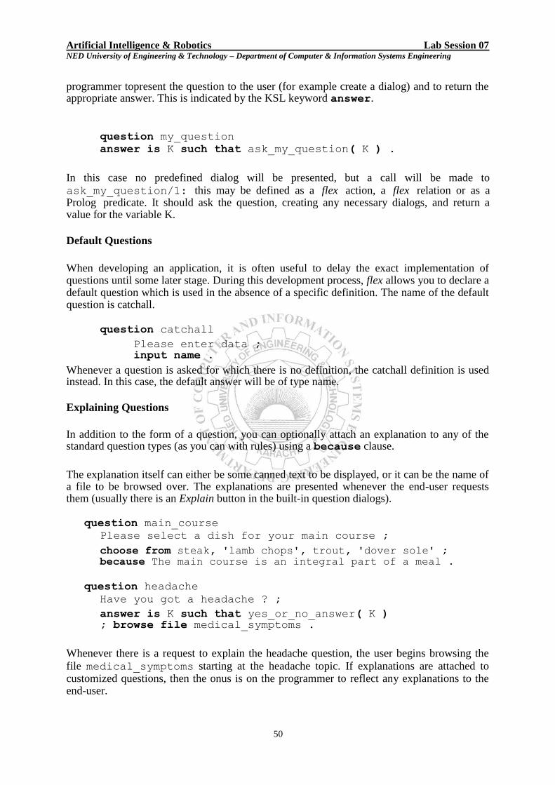
Artificial Intelligence & Robotics Lab Session 07 NED University of Engineering & Technology – Department of Computer & Information Systems Engineering programmer topresent the question to the user (for example create a dialog) and to return the appropriate answer. This is indicated by the KSL keyword answer.
question my_question answer is K such that ask_my_question( K ) .
In this case no predefined dialog will be presented, but a call will be made to ask_my_question/1: this may be defined as a flex action, a flex relation or as a Prolog predicate. It should ask the question, creating any necessary dialogs, and return a value for the variable K.
Default Questions
When developing an application, it is often useful to delay the exact implementation of questions until some later stage. During this development process, flex allows you to declare a default question which is used in the absence of a specific definition. The name of the default question is catchall.
question catchall
Please enter data ; input name .
Whenever a question is asked for which there is no definition, the catchall definition is used instead. In this case, the default answer will be of type name.
Explaining Questions
In addition to the form of a question, you can optionally attach an explanation to any of the standard question types (as you can with rules) using a because clause.
The explanation itself can either be some canned text to be displayed, or it can be the name of a file to be browsed over. The explanations are presented whenever the end-user requests them (usually there is an Explain button in the built-in question dialogs).
question main_course Please select a dish for your main course ;
choose from steak, 'lamb chops', trout, 'dover sole' ; because The main course is an integral part of a meal .
question headache
Have you got a headache ? ;
answer is K such that yes_or_no_answer( K ) ; browse file medical_symptoms .
Whenever there is a request to explain the headache question, the user begins browsing the
file medical_symptoms starting at the headache topic. If explanations are attached to customized questions, then the onus is on the programmer to reflect any explanations to the end-user.
50

Artificial Intelligence & Robotics Lab Session 07 NED University of Engineering & Technology – Department of Computer & Information Systems Engineering (Note that the following example will not work in MacProlog since there is no support for byte-level keyboard input.)
Example:
question headache answer
is K such that
write( 'Have you got a headache ?' ) and yes_no_question( K, medical_symptoms ) .
action yes_no_question( K, File ) ;
do write( 'Please type Y or N or ESC' ) and repeat and get0( Byte ) and yes_or_no_check( Byte, K, File ) and ! .
relation yes_or_no_check( 89, yes, File ) .
relation yes_or_no_check( 121, yes, File ) .
relation yes_or_no_check( 78, no, File ) .
relation yes_or_no_check( 110, no, File ) .
relation yes_or_no_check( 26, _, File )
if browse( File ) and fail .
Invoking Questions
There are two underlying procedures, ask/1 and answer/2, for invoking questions. These are reflected in the KSL as the directive.
ask <name of
question> and as the term
answer to <name of question>
respectively. These built-in procedures behave quite differently at run-time. Whenever there is a request to ask a question, that question is always asked immediately. However, a request
for the answer to a question will only invoke that question if it has not previously been
asked. If the behaviour of an application is such that the same question should be asked once, and only once, then use the answer to construct.
action decide_meal ;
do ask main_course and ask vegetables .
In this case, using ask, the question dialogs will be displayed every time the decide_meal
action is executed. The global values of main_course and vegetables will therefore change for each invocation of the decide_meal action.
51
Artificial Intelligence & Robotics Lab Session 07 NED University of Engineering & Technology – Department of Computer & Information Systems Engineering
rule prescription1
if the answer to headache is yes
and the answer to pregnant is no
then prescribe( paracetamol ) .
rule prescription2
if the answer to headache is yes and the answer to pregnant is yes then prescribe( nothing ) .
In this example, the actual questions headache and pregnant will only be asked if they haven‘t previously been asked. Once there is a value for each of headache and pregnant, this value will be used for the rest of the session. The questions headache and pregnant will therefore only be asked once. Rules and Relations
In order to distinguish between rules which are intended to be used in a forward chaining manner from those which are to be used in a backward chaining manner, flex uses different rule formats and different KSL keywords. Forward chaining rules are indicated by the
keyword rule; backward chaining rules are indicated by the keyword relation. Both
formats fit the classical if-then style, but whereas backward chaining relations allow only for a single, positive conclusion in the then part, there is no such restriction in forward chaining rules which may have multiple conclusions, any of which may be either positive or negative in nature. Forward chaining rules often contain an action as part of their conclusion. This action usually updates various data (slot) values, which means that different rules will or will not fire next time round the forward chaining cycle.
Backward chaining, on the other hand, generally seeks to establish a logical sequence of rules and facts in order to prove a clause or goal. This does not involve rule firing or executing actions, but is of a more deductive nature.
Weighting of Rules
In rule-based systems there are always choice points where one rule is preferred to another. Attaching weights to rules is an option which can assist in making those decisions. The weight of a rule reflects its relative importance with respect to the other rules in the system. Whenever two or more rules are simultaneously applicable, their relative weights can be compared to decide which one to use. Most weighting systems will be static, with each rule being assigned a specific score. The more important the rule, the higher its score should be. So, in the example below, if we have plenty of beer in the fridge, and the weather is hot, and it's late, then we will always drink beer regardless of the order of the rules.
rule drink_tea
if the hour is late then drink_a_cup_of_tea score 5 .
rule drink_beer
52

Artificial Intelligence & Robotics Lab Session 07 NED University of Engineering & Technology – Department of Computer & Information Systems Engineering
if the fridge contains some beer and the weather is hot
then drink_a_can_of_beer score 10 .
In addition, flex allows for dynamic weighting systems whereby the score attached to a rule is not fixed when the rule is defined, but is dependent upon some changing information. For example, suppose we have a rule-based system for controlling the flow of materials between different storage vessels in a chemical plant, which contains a rule
empty_master_into_slave. It is not easy to give an exact score for this rule which is
accurate in all circumstances. At certain times this may be the most appropriate rule, but at other times there may be another rule, say emptying the master vessel completely, that is more important. To reflect this dependence upon the current circumstances, we can give the rule a dynamic score.
rule empty_master_into_slave
if the master is not empty and the slave`s contents > the master`s spare_capacity
then fill_from( master, slave ) score master`s contents plus slave`s contents .
As the contents of the two vessels change, so the weighting of this rule also changes. We could even give the system a sense of chance by using random-valued scores.
Attaching Explanations to Rules
The final part of a production rule in flex involves the attachment of an optional explanation to rules. This is used to explain why a rule was fired. The explanation itself can either be some canned text or a pointer to a disk file accessed at run-time through a file browser. When explaining the rule either the canned text is displayed on screen or the user is allowed to browse through the file.
rule 'check status' if the applicant`s job is officer
and the applicant`s age is greater than 65 then ask_for_grading because The job grading affects the pension .
The above rule will cause the single line of text The job grading affects the
pension to be displayed on the screen whenever an explanation is requested. The latter alternative allows for a more flexible explanation facility. Indeed, the only purpose of the rule-based system might be as an intelligent link into the file browsing system. Such applications include the reviewing of technical manuals, especially medical journals.
rule 'check status'
if the applicant`s job is principal
and the applicant`s age is greater than 65 then check_principal_function
53

Artificial Intelligence & Robotics Lab Session 07 NED University of Engineering & Technology – Department of Computer & Information Systems Engineering
browse file status .
The Forward Chaining Engine
The forward chaining engine is implemented as a Prolog program. The emphasis of the implementation is placed upon simplicity coupled with great flexibility, rather than extracting the highest possible performance. Ruleset
Rules are grouped together into rulesets, and forward chaining is started using the KSL keywords invoke ruleset. This provides a construct for forming rules into stratified rule-bases and governing the forward-chaining engine in terms of rule selection method and agenda updating.
For example, to move a piece in a game we might have a ruleset called make_move containing rules for possible moves.
ruleset make_move contains corner_move, edge_move, centre_move .
action move ;
invoke ruleset make_move .
The Rule Agenda
The rule agenda determines the rules currently available to the inference engine during forward chaining (initially specified by a ruleset). It might include all of the rules in the system, or only a subset. The rule agenda may contain duplicates, and there are no restrictions whatsoever on which names can go into the list. After a rule has been selected and fired, the rule agenda may be updated, and it is this revised agenda that the inference engine uses as the basis for the next cycle.
Setting The Initial Rule Agenda
The initial rule agenda is the set of rules from which the forward chaining engine makes its first selection. The initial rule agenda may be specified as containing all rules, a list of rules or a rule group. The only mandatory part of a given ruleset is the definition of the initial rule agenda.
ruleset everything
contains all rules .
This KSL sentence sets the initial rule agenda to contain all the rules currently defined.
Rules Selection
A vital part of any engine, whether forward or backward chaining, is the method by which rules are selected. flex provides three built-in methods for selecting rules:
54

Artificial Intelligence & Robotics Lab Session 07 NED University of Engineering & Technology – Department of Computer & Information Systems Engineering
First come first served
Conflict resolution
Conflict resolution with a threshold.
In addition, there is a facility for hooking in user-defined selection algorithms.
First Come First Served
The first come first served selection algorithm simply chooses the first rule in the
agenda whose conditions (the if part) are all satisfied. First come first served is the default selection algorithm for the ruleset. For example;
ruleset mover contains push, pull, lift .
ruleset make_tea
contains all rules ; select rule using first come first served .
The selection algorithm used in both of these examples will be first come first served.
Conflict Resolution
Conflict resolution is a more sophisticated and computationally expensive selection scheme whereby the "best" rule is always selected. A conflict occurs when more than one rule can be fired (i.e. the if conditions of more than one rule are satisfied). This conflict is then resolved
by choosing the rule with the highest score. In the event of a tie the first is chosen. For Example;
ruleset mover.
contains push, pull, lift select rule using conflict resolution .
Conflict Resolution with Threshold Values
A compromise between these two contrasting selection schemes, (first come first served and conflict resolution), is to introduce threshold values into the latter. This offers a conflict resolution scheme in principle, but which stops as soon as a candidate is found whose score is greater than the threshold value.
For example, if the agenda contained 1000 rules we might strike lucky and find that the 5 th rule can not only be fired, but also that its score is above the threshold value that has been set. Thus this rule will be fired with no further searching.
ruleset make_tea contains all rules ;
select rule using conflict resolution
with threshold 6 .
55

Artificial Intelligence & Robotics Lab Session 07 NED University of Engineering & Technology – Department of Computer & Information Systems Engineering
Updating the Agenda
At the end of each cycle of the engine, the agenda can be updated according to the name of the rule which was fired. The default is to leave the set of rules exactly as it is, so that the rules are always considered in the same order every time.
EXERCISES
1. Write a program, which takes information a car (model, make, color, engine, registration
number and country from where it is imported) as input, and displays it on screen. ________________________________________________________________ ________________________________________________________________
________________________________________________________________
________________________________________________________________ ________________________________________________________________
________________________________________________________________ ________________________________________________________________ ________________________________________________________________
________________________________________________________________ ________________________________________________________________
________________________________________________________________ ________________________________________________________________
_____________________________________________________________
2. Write a program for Menu selection in a restaurant. Make use of Choose some of clause. ________________________________________________________________
________________________________________________________________ ________________________________________________________________ ________________________________________________________________
________________________________________________________________ ________________________________________________________________
________________________________________________________________ ________________________________________________________________ ________________________________________________________________ ________________________________________________________________ ________________________________________________________________ ________________________________________________________________ ________________________________________________________________ ________________________________________________________________
3. Write a program suggesting user an appropriate dress for an occasion, making use of ruleset. Compose questions asking user about gender, weather condition, place, type of
56

Artificial Intelligence & Robotics Lab Session 07 NED University of Engineering & Technology – Department of Computer & Information Systems Engineering occasion, number of persons invited and relation with host/organizers etc. and suggest suitable outfit.
__________________________________________________
__________________________________________________
__________________________________________________
__________________________________________________
__________________________________________________
__________________________________________________
__________________________________________________
__________________________________________________
__________________________________________________
__________________________________________________
__________________________________________________
__________________________________________________
__________________________________________________
__________________________________________________
__________________________________________________
__________________________________________________
__________________________________________________
__________________________________________________
__________________________________________________
__________________________________________________
__________________________________________________
__________________________________________________
__________________________________________________
__________________________________________________
__________________________________________________
__________________________________________________
__________________________________________________
__________________________________________________
__________________________________________________
__________________________________________________
57

Artificial Intelligence & Robotics Lab Session 07 NED University of Engineering & Technology – Department of Computer & Information Systems Engineering
__________________________________________________
__________________________________________________
__________________________________________________
__________________________________________________
__________________________________________________
__________________________________________________
__________________________________________________
__________________________________________________
__________________________________________________
__________________________________________________ 4. Consider scenario of issuance of credit card to customers. Write a program which makes some decision whether credit card should be issued to a particular customer depending upon different conditions and codify it using ruleset.
__________________________________________________
__________________________________________________
__________________________________________________
__________________________________________________
__________________________________________________
__________________________________________________
__________________________________________________
__________________________________________________
__________________________________________________
__________________________________________________
__________________________________________________
__________________________________________________
__________________________________________________
__________________________________________________
__________________________________________________
__________________________________________________
__________________________________________________
__________________________________________________
__________________________________________________
__________________________________________________
58

Artificial Intelligence & Robotics Lab Session 07 NED University of Engineering & Technology – Department of Computer & Information Systems Engineering
__________________________________________________
__________________________________________________
__________________________________________________
__________________________________________________
__________________________________________________
__________________________________________________
__________________________________________________
__________________________________________________
__________________________________________________
__________________________________________________
__________________________________________________
__________________________________________________
__________________________________________________
__________________________________________________
__________________________________________________
__________________________________________________
__________________________________________________
__________________________________________________
__________________________________________________
__________________________________________________
__________________________________________________
__________________________________________________
__________________________________________________
__________________________________________________
__________________________________________________
__________________________________________________
__________________________________________________
__________________________________________________
_________________________________________________
59

Artificial Intelligence & Robotics Lab Session 08 NED University of Engineering & Technology – Department of Computer & Information Systems Engineering
Lab Session 08
OBJECT
Learning Data-Driven programming concepts Data Driven Programming
The frame system of flex can be used for the representation of data and knowledge. In this chapter we describe data-driven programming, where rather than program the control-flow or logic of a system, procedures are attached to individual frames or groups of frames. These procedures lie dormant and are activated whenever there is a request to update, access or create an instance of the frame or slot to which they are attached. This concept of attached procedures, sometimes referred to as active values, is also found in object-oriented programming.
Data-Driven Procedures There are four types of data-driven procedures:
Launches
Watchdogs
Constraints
Demons
The following diagram shows when and where the various procedures are invoked.
Figure 8.1
Launches A launch procedure is activated whenever there is a request to create an instance of the frame to which it is attached.
A launch procedure has three main parts:
context A test to see whether certain conditions hold.
60
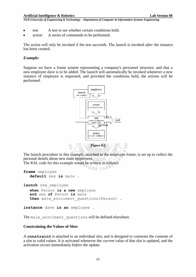
Artificial Intelligence & Robotics Lab Session 08 NED University of Engineering & Technology – Department of Computer & Information Systems Engineering
test A test to see whether certain conditions hold.
action A series of commands to be performed.
The action will only be invoked if the test succeeds. The launch is invoked after the instance has been created.
Example:
Suppose we have a frame system representing a company's personnel structure, and that a new employee dave is to be added. The launch will automatically be invoked whenever a new instance of employee is requested, and provided the conditions hold, the actions will be performed.
Figure 8.2
The launch procedure in this example, attached to the employee frame, is set up to collect the personal details about new male employees. The KSL code for this example would be written as follows: frame employee
default sex is male .
launch new_employee
when Person is a new employee and sex of Person is male then male_enrolment_questions(Person) .
instance dave is an employee .
The male_enrolment_questions will be defined elsewhere.
Constraining the Values of Slots
A constraint is attached to an individual slot, and is designed to constrain the contents of a slot to valid values. It is activated whenever the current value of that slot is updated, and the activation occurs immediately before the update.
61

Artificial Intelligence & Robotics Lab Session 08 NED University of Engineering & Technology – Department of Computer & Information Systems Engineering
A constraint has three main parts:
context A test to see whether certain conditions hold.
check A test to see whether the update is valid.
error A series of commands to be performed for an invalid update. The check will only be made if the context holds. If the check is successful then the update is allowed, otherwise the error commands are invoked and the update is not allowed.
Example:
If we had a frame system representing instances of water containers, we could put a constraint on the contents slot of any jug, such that when the value for the particular slot is being updated, a test is performed making sure that the new value is less than the value of the jug`s capacity, thus ensuring the jug does not overflow!
In the example the constraint is activated if the contents attribute of any jug changes. The prospective new value for the slot is then tested to see if it is less than that jug's capacity. If the test succeeds the update is allowed. If the test fails the update is not allowed and a message is displayed.
Figure 8.3 The code for this example could be written as follows: frame jug
default contents are 0 and default capacity is 7 .
instance jug1 is a jug .
constraint check_contents
when the contents of Jug changes to X and Jug is some jug
then check that number( X ) and X =< Jug`s capacity
otherwise write( 'contents not updated' ) and nl .
62

Artificial Intelligence & Robotics Lab Session 08 NED University of Engineering & Technology – Department of Computer & Information Systems Engineering
Note the use of Jug, a local variable, which will unify with any frame or instance which has, in this case, a contents attribute.
Attaching Demons to Slot Updates
A demon is attached to an individual slot. It is activated whenever the current value of that slot is updated, and the activation occurs immediately after the update.
A demon has two main parts: context A test to see whether certain conditions hold.
action A series of commands to be performed.
The slot is updated and then, given that the context holds, the actions will be invoked.
A demon can be tailored such that it fires only for given values and/or only under certain circumstances.
Example:
If we are modelling the action of kettles, we could attach a demon to the temp slot of any instance of the frame kettle.
Figure 8.4
Whenever the temp slot is updated, a check will be made on the new value, such that, if it is greater than 100, then the actions make_steam and whistle are performed.
The code for this example could be written as follows: frame kettle
default temp is 0 .
instance kettle1 is a kettle .
demon kettle_boiling
63

Artificial Intelligence & Robotics Lab Session 08 NED University of Engineering & Technology – Department of Computer & Information Systems Engineering
when the temp changes to T and T is greater than 100 then make_steam and nl and whistle .
Restricting the Access to Slots
A watchdog is attached to an individual slot. It is activated whenever the current value of the slot is accessed. A watchdog has three main parts:
context A test to see whether certain conditions hold.
check A test to see whether the access is valid.
error A series of commands to be performed if access is invalid. The check will only be made if the context holds. If the check is successful then the access is allowed. Otherwise, the error commands are invoked and the access is denied. A watchdog can be used to check the access rights to an attribute of a frame. It is invoked whenever there is a request for the current value (not the default value) of that slot (attribute-frame pair).
Example:
In the example shown below, the watchdog is activated when the contents of a file are requested. A check on the user's classification is then made, and if the check succeeds the access is allowed. If the check fails the access is denied and a warning message is displayed.
The KSL for a similar example is shown below. In this case, only users with sufficiently high access priority may find out the balance in a bank account.
The current_user frame stores the access code of the current user, which is checked in the account_security watchdog.
frame bank_account
default balance is 0.
frame current_user
default name is '' and
default access is 0.
watchdog account_security
when the balance of Account is requested and Account is some bank_account
then check current_user`s access is above 99 otherwise write( 'Balance access denied to user ' ) and write( current_user`s name ).
64

Artificial Intelligence & Robotics Lab Session 08 NED University of Engineering & Technology – Department of Computer & Information Systems Engineering
EXERCISES 1. Define a frame ―Kettle‖ and make use of launch procedure to create some instances.
__________________________________________________
__________________________________________________
__________________________________________________
__________________________________________________
__________________________________________________
__________________________________________________
__________________________________________________
__________________________________________________
__________________________________________________
__________________________________________________
__________________________________________________
__________________________________________________
__________________________________________________
__________________________________________________
__________________________________________________
__________________________________________________
__________________________________________________
__________________________________________________
__________________________________________________
__________________________________________________
__________________________________________________
__________________________________________________
__________________________________________________
__________________________________________________
__________________________________________________
__________________________________________________
__________________________________________________
__________________________________________________
__________________________________________________
__________________________________________________
__________________________________________________
65

Artificial Intelligence & Robotics Lab Session 08 NED University of Engineering & Technology – Department of Computer & Information Systems Engineering
2. Write a program which checks different conditions and permits/restricts user from accessing the attribute values. Use the scenario of ―Bank Account‖.
__________________________________________________
__________________________________________________
__________________________________________________
__________________________________________________
__________________________________________________
__________________________________________________
__________________________________________________
__________________________________________________
__________________________________________________
__________________________________________________
__________________________________________________
__________________________________________________
__________________________________________________
__________________________________________________
__________________________________________________
__________________________________________________
__________________________________________________
__________________________________________________
__________________________________________________
__________________________________________________
__________________________________________________
__________________________________________________
__________________________________________________
__________________________________________________
__________________________________________________
__________________________________________________
__________________________________________________
__________________________________________________
__________________________________________________
__________________________________________________
__________________________________________________
66

Artificial Intelligence & Robotics Lab Session 08 NED University of Engineering & Technology – Department of Computer & Information Systems Engineering
__________________________________________________
__________________________________________________
__________________________________________________
_________________________________________________
__________________________________________________
__________________________________________________
67

Section Three
Robotics
65

Artificial Intelligence & Robotics Lab Session 09 NED University of Engineering & Technology – Department of Computer & Information Systems Engineering
Lab Session 09 OBJECT
Introducing the Parallax Boe-Bot® robot
THEORY Introduction: Robots are used in the auto, medical, and manufacturing industries, in all manner of exploration vehicles. Building and programming a robot is a combination of mechanics, electronics, and problem solving. What you're about to learn while doing the activities and projects in the coming lab sessions will be relevant to real-world applications that use robotic control, the only differences being the size and sophistication. The mechanical principles, example program listings, and circuits you will use are very similar to, and sometimes the same as, industrial applications developed by engineers. The goal of these lab sessions is to get students interested in and excited about the fields of engineering, mechatronics, and software development as they design, construct, and program an autonomous robot. This series of hands-on activities and tasks will introduce students to basic robotic concepts using the Parallax Boe-Bot® robot, called the "Boe-Bot." Its name comes from the Board of Education® carrier board that is mounted on its wheeled chassis. An example of a Boe-Bot with an infrared obstacle detection circuit built on the Board of Education solderless prototyping area is shown in Figure 9-1.
Figure 9-1: Parallax Inc.‘s Boe-Bot® Robot The activities and tasks in this and coming lab sessions begin with an introduction to your Boe-Bot‘s brain, the Parallax BASIC Stamp® 2 microcontroller, and then move on to construction, testing, and calibration of the Boe-Bot. After that, you will program the Boe-Bot for basic maneuvers, and then proceed to adding sensors and writing programs that make it react to its surroundings and perform autonomous tasks.
Boe-Bot’s Brain: Parallax, Inc‘s Boe-Bot® robot is the focus of the activities, projects, and contests in coming lab sessions. The Boe-Bot and a close-up of its BASIC Stamp® 2 programmable microcontroller brain are shown in Figure 9-2. The BASIC Stamp 2 module is both powerful and easy to use, especially with a robot.
Figure 9-2: BASIC Stamp Module on a Boe-Bot Robot
66

Artificial Intelligence & Robotics Lab Session 09 NED University of Engineering & Technology – Department of Computer & Information Systems Engineering The activities will guide you through writing simple programs that make the BASIC Stamp and your Boe-Bot do four essential robotic tasks: 1. Monitor sensors to detect the world around it
2. Make decisions based on what it senses 3. Control its motion (by operating the motors that make its wheels turn) 4. Exchange information with its Roboticist (that will be you!)
The programming language you will use to accomplish these tasks is called PBASIC, which stands for: Parallax - Company that invented and manufactures BASIC Stamp microcontrollers Beginners - Made for beginners to learn how to program computers All-purpose - Powerful and useful for solving many different kinds of problems Symbolic - Using symbols (terms that resemble English word/phrases) Instruction - To tell a computer what to do Code - In terms that the computer (and you) can understand
Hardware and Software: Getting started with BASIC Stamp microcontroller modules is similar to getting started with a brand-new PC or laptop. The first things that most people have to do is take it out of the box, plug it in, install and test some software, and maybe even write some software of their own using a programming language. The BASIC Stamp Editor (version 2.5 or higher) is the software you will use in the activities. You will use this software to write programs that the BASIC Stamp module will run. You can also use this software to display messages sent by the BASIC Stamp that help you understand what it senses. Using the help file for hardware setup: In this section you will run the BASIC Stamp Editor‘s Help file. Within the Help file, you will learn about the different BASIC Stamp programming boards available for the Stamps, and determine which one you are using. Then, you will follow the steps in the Help to connect your hardware to your computer and test your BASIC Stamp programming system. Running the BASIC Stamp Editor for the first time
If you see the BASIC Stamp Editor icon on your computer desktop, double-click it (Figure 9-3).
Or, click on your computer‘s Start menu, then choose All Programs Parallax Inc. BASIC Stamp Editor 2.5 BASIC
Stamp Editor 2.5.
Figure 9-3: BASIC Stamp Editor Desktop Icon
On the BASIC Stamp Editor‘s toolbar, click Help on the toolbar (Figure 9-4) and then select BASIC Stamp Help… from the drop-down menu.
Figure 9-4: Opening the Help Menu The BASIC Stamp Editor Help wizard will open as shown in Figure 9-5.
67

Artificial Intelligence & Robotics Lab Session 09 NED University of Engineering & Technology – Department of Computer & Information Systems Engineering
Figure 9-5: BASIC Stamp Editor Help
Click on the ―Getting Started with Stamps in Class” link on the bottom of the Welcome page, as shown in the lower right corner of Figure 9-5. Following the Directions in the Help File: From here, you will follow the directions in the Help file to complete these tasks:
Identify which BASIC Stamp development board you are using
Connect your development board to your computer
Test your programming connection
Troubleshoot your programming connection, if necessary
Write your first PBASIC program for your BASIC Stamp
Power down your hardware when you are done
Exercise:
1. There is a problem with these two commands. When you run the code, the numbers they display are stuck together so that it looks like one large number instead of two small ones. Modify these two commands so that the answers appear on different lines in the Debug Terminal.
DEBUG DEC 7 * 11 DEBUG DEC 7 + 11
__________________________________________________________________________________________ __________________________________________________________________________________________ __________________________________________________________________________________________
2. Use DEBUG to display the solution to the math problem: 1 + 2 + 3 + 4. __________________________________________________________________________________________ __________________________________________________________________________________________
__________________________________________________________________________________________ __________________________________________________________________________________________ __________________________________________________________________________________________ __________________________________________________________________________________________
3. Save FirstProgramYourTurn.bs2 (given in the help file) under another name. If you were to place the
DEBUG command shown below on the line just before the END command in the program, what other
68

Artificial Intelligence & Robotics Lab Session 09 NED University of Engineering & Technology – Department of Computer & Information Systems Engineering
lines could you delete and still have it work the same? Modify the copy of the program to test your hypothesis (your prediction of what will happen).
DEBUG "What's 7 X 11?", CR, "The answer is: ", DEC 7 * 11
__________________________________________________________________________________________ __________________________________________________________________________________________ __________________________________________________________________________________________ __________________________________________________________________________________________ __________________________________________________________________________________________ __________________________________________________________________________________________ __________________________________________________________________________________________ __________________________________________________________________________________________ __________________________________________________________________________________________ __________________________________________________________________________________________ __________________________________________________________________________________________ __________________________________________________________________________________________ __________________________________________________________________________________________ __________________________________________________________________________________________ __________________________________________________________________________________________
69

Artificial Intelligence & Robotics Lab Session 10 NED University of Engineering & Technology – Department of Computer & Information Systems Engineering
Lab Session 10 OBJECT
Introducing the Boe-Bot’s Servo Motors
THEORY
Introduction: Continuous Rotation Servo The Parallax Continuous Rotation servos shown in Figure 10-1 are the motors that will make the Boe-Bot‘s wheels turn. This figure points out the servos‘ external parts. Many of these parts will be referred to as you go through the instructions in this and the next lab session.
Figure 10-1: Parallax Continuous Rotation Servo TASK 1: Tracking Time and Repeating Actions with a Circuit Controlling a servo motor‘s speed and direction involves a program that makes the BASIC Stamp send the same message, over and over again. The message has to repeat itself around 50 times per second for the servo to maintain its speed and direction. This activity will demonstrate how to repeat the same message over and over again and control the timing of the message.
Displaying Messages at Human Speeds You can use the PAUSE command to tell the BASIC Stamp to wait for a while before executing the next command. PAUSE Duration The number that you put to the right of the PAUSE command is called the Duration argument, and it‘s the value that tells the BASIC Stamp how long it should wait before moving on to the next command. The units for the Duration argument are thousandths of a second (ms). So, if you want to wait for one second, use a value of 1000. Here‘s how the command should look: PAUSE 1000 If you want to wait for twice as long, try: PAUSE 2000 The longest possible Duration argument is 65535. Example Program: TimedMessages.bs2 There are lots of different ways to use the PAUSE command. This example program uses PAUSE to delay between printing messages that tell you how much time has elapsed. The program should wait one second before it sends the ―One second elapsed…‖ message and another two seconds before it displays the ―Three seconds elapsed . . .‖ message.
Move the 3-postion switch of the Board of Education from position-0 to position-1.
Enter the program below into the BASIC Stamp Editor.
70

Artificial Intelligence & Robotics Lab Session 10 NED University of Engineering & Technology – Department of Computer & Information Systems Engineering
Save the program under the name TimedMessages.bs2.
Run the program, and then watch for the delay between messages.
' Robotics with the Boe-Bot - TimedMessages.bs2 ' Show how the PAUSE command can be used to display messages at human speeds. ' {$STAMP BS2} ' {$PBASIC 2.5} DEBUG "Start timer..." PAUSE 1000 DEBUG CR, "One second elapsed..." PAUSE 2000 DEBUG CR, "Three seconds elapsed..." DEBUG CR, "Done." END
Over and Over Again
You can place your commands between the words DO and LOOP if you want them executed over and over again. For example, let‘s say you want to print a message repeating once every second. Simply place your DEBUG and PAUSE commands between the words DO and LOOP like this: DO DEBUG "Hello!", CR PAUSE 1000 LOOP Example Program: HelloOnceEverySecond.bs2
Enter, save, and run HelloOnceEverySecond.bs2.
Verify that the ―Hello!‖ message is printed once every second.
' Robotics with the Boe-Bot - HelloOnceEverySecond.bs2 ' Display a message once every second. ' {$STAMP BS2} ' {$PBASIC 2.5} DO DEBUG "Hello!", CR PAUSE 1000 LOOP
TASK 2: Building and Testing the Led Circuit In this activity, you will build circuits that emit light that will allow you to ―see‖ the kind of signals that are used to control the Boe-Bot‘s servo motors.
LED Test Circuit Parts (2) LEDs – Red (2) Resistors, 470 Ω (yellow-violet-brown)
LED Test Circuit Build the circuit shown in Figure 10-2.
Make sure that the shorter pins on each LED (the cathodes) are plugged into black sockets labeled Vss.
Make sure the longer pins (the anodes, marked with a + in the wiring diagram) are connected to the white breadboard sockets exactly as shown.
71

Artificial Intelligence & Robotics Lab Session 10 NED University of Engineering & Technology – Department of Computer & Information Systems Engineering
Figure 10-2: Two LEDs Connected to BASIC Stamp I/O Pins P13 and P12 Schematic (left) and wiring diagram (right)
Figure 10-3 shows what you will program the BASIC Stamp to do to the LED circuit. Imagine that you have a 5 volt (5 V) battery. Although a 5 V battery is not common, the Board of Education has a device called a voltage regulator that supplies the BASIC Stamp with the equivalent of a 5 V battery. When you connect a circuit to Vss, it‘s like connecting the circuit to the negative terminal of the 5 V battery. When you connect the other end of the circuit to Vdd, it‘s like connecting it to the positive terminal of a 5 V battery.
Figure 10-3: Current and Electron Flow When these connections are made, 5 V of electrical pressure is applied to the circuit causing electrons to flow through and the LED to emit light. As soon as you disconnect the resistor lead from the battery‘s positive terminal, the current stops flowing, and the LED stops emitting light. You can take it one step further by connecting the resistor lead to Vss, which has the same result. This is the action you will program the BASIC Stamp to do to make the LED turn on (emit light) and off (not emit light).
Programs that Control the LED Test Circuits The HIGH and LOW commands can be used to make the BASIC Stamp connect an LED alternately to Vdd and Vss. The Pin argument is a number between 0 and 15 that tells the BASIC Stamp which I/O pin to connect to Vdd or Vss. HIGH Pin LOW Pin For example, if you use the command: HIGH 13 ...it tells the BASIC Stamp to connect I/O pin P13 to Vdd, which turns the LED on. Likewise, if you use the command: LOW 13 ...it tells the BASIC Stamp to connect I/O pin P13 to Vss, which turns the LED off. Let‘s try this out. Example Program: HighLowLed.bs2
Reconnect power to your board.
Enter, save, and run HighLowLed.bs2.
Verify that the LED circuit connected to P13 is turning on and off, once every second.
72

Artificial Intelligence & Robotics Lab Session 10 NED University of Engineering & Technology – Department of Computer & Information Systems Engineering ' Robotics with the Boe-Bot – HighLowLed.bs2 ' Turn the LED connected to P13 on/off once every second. ' {$STAMP BS2} ' {$PBASIC 2.5} DEBUG "The LED connected to Pin 13 is blinking!" DO HIGH 13 PAUSE 500 LOW 13 PAUSE 500 LOOP
Viewing a Servo Control Signal with an LED
The high and low signals you will program the BASIC Stamp to send to the servo motors must last for very precise amounts of time. That‘s because the servo motors measure the amount of time the signal stays high, and use it as an instruction for where to turn. For accurate servo motor control, the time these signals stay high must be much more precise than you can get with a HIGH and a PAUSE command. You can only change the PAUSE command‘s Duration argument by 1 ms (remember, that‘s 1/1000 of a second) at a time. There‘s a different command called PULSOUT that can deliver high signals for precise amounts of time. These amounts of time are values you use in the Duration argument, and they are measured in units that are two millionths of a second! PULSOUT Pin, Duration A microsecond is a millionth of a second abbreviated as μs. You can send a HIGH signal that turns the P13 LED on for 2 μs (that‘s two millionths of a second) by using this command: PULSOUT 13, 1 Following command would turn the LED on for 4 μs: PULSOUT 13, 2 And the command below sends a high signal that you can actually view: PULSOUT 13, 65000 How long does the LED circuit connected to P13 stay on when you send this pulse? Let‘s figure it out. The time it stays on is 65000 times 2 μs. That‘s: Duration = 65000 x 2μs
= 65000x 0.000002s
= 0.13 s ...this is still pretty fast, thirteen hundredths of a second. Example Program: PulseP13Led.bs2 In this program, the high signal will last for 0.13 seconds, and the low signal for 2 seconds. This is 100 times slower than the signal that the servo will need to control its motion.
Enter, save, and run PulseP13Led.bs2.
Verify that the LED circuit connected to P13 pulses for about thirteen hundredths of a second, once every two seconds.
' Robotics with the Boe-Bot – PulseP13Led.bs2 ' Send a 0.13 second pulse to the LED circuit connected to P13 every 2s. ' {$STAMP BS2} ' {$PBASIC 2.5} DEBUG "Program Running!" DO PULSOUT 13, 65000 PAUSE 2000 LOOP
TASK 3: Connecting the Servo Motors In this activity, you will build a circuit that connects the servo to a power supply and a BASIC Stamp I/O pin. The LED circuits you developed in the previous task will be used later to monitor the signals the BASIC Stamp sends to the servos to control their motion.
73

Artificial Intelligence & Robotics Lab Session 10 NED University of Engineering & Technology – Department of Computer & Information Systems Engineering
Parts for Connecting the Servos (2) Parallax Continuous Rotation servos (2) Built and tested LED circuits from the previous activity
Connecting the Servos to the Board of Education Turn off the power by setting the 3-position switch on your Board of Education to position-0.
Figure 10-4 shows the servo header on the Board of Education. This board features a jumper that you can use to connect the servo‘s power supply to either Vin or Vdd. To move it, you have to pull it upwards and off the pair of pins it rests on, then push it onto the pair of pins you want it to rest on.
If you are using the 6 V battery pack, make sure the jumper between the servo ports on the Board of Education is set to Vin as shown on the left of Figure 10-4.
If you are using a 7.5 V, 1000 mA center positive DC supply, set the jumper to Vdd as shown on the right side of Figure 10-4.
Figure 10-4: Selecting Your Servo Ports‘ Power Supply on the Board of Education
Figure 10-5 shows the schematic of the circuit you will build on the Board of Education. The jumper is set to Vin.
Connect your servos to your Board of Education as shown in Figure 10-5.
Figure 10-5: Servo Connections for the Board of Education
When you are done assembling the system, it should resemble Figure 10-6 (LED circuits not shown).
74

Artificial Intelligence & Robotics Lab Session 10 NED University of Engineering & Technology – Department of Computer & Information Systems Engineering
Figure 10-6: Board of Education with Servos and Battery Pack Connected
If you removed the LED circuits after task 2, make sure to rebuild them as shown in Figure 10-7. They will be your servo signal
monitoring circuits.
Figure 10-7: LED Servo Signal Monitor Circuit TASK4: Centering the Servos In this activity, you will run a program that sends the servos a signal, instructing them to stay still. Because the servos are not pre-adjusted at the factory, they will instead start turning. You will then use a screwdriver to adjust them so that they stay still. This is called centering the servos. After the adjustment, you will test the servos to make sure they are functioning properly. The test programs will send signals that make the servos turn clockwise and counterclockwise at various speeds.
Servo Tools and Parts The Parallax screwdriver shown in Figure 10-8 is the only extra tool you will need for this activity.
Figure 10-8: Parallax Screwdriver
Sending the Center Signal Figure 10-9 shows the signal that has to be sent to the servo connected to P12 to calibrate it. This is called the center signal, and after the servo has been properly adjusted, this signal instructs it to stay still. The instruction consists of a series of 1.5 ms pulses with 20 ms pauses between each pulse.
75

Artificial Intelligence & Robotics Lab Session 10 NED University of Engineering & Technology – Department of Computer & Information Systems Engineering
Figure 10-9: Timing Diagram for CenterServoP12.bs2
The 1.5 ms pulses instruct the servo to remain still. The program for this signal will be a PULSOUT command and a PAUSE command inside a DO…LOOP. Figuring out the PAUSE command from the timing diagram is easy; it's going to be PAUSE 20 for the 20 ms between
pulses. Figuring out the PULSOUT command's Pin argument isn't that hard either; it's going to be 12, for I/O pin P12. Next, let's figure out what the PULSOUT command's Duration argument has to be for 1.5 ms pulses. 1.5 ms is 1.5 thousandths of a second, or 0.0015 s. Remember whatever number is in the PULSOUT command's Duration argument, multiply that number by 2 μs (2 millionths of a second = 0.000002 s), and you will know how long the pulse will last. You can also figure out what the PULSOUT command's Duration argument has to be if you know how long you want the pulse to last. Just divide 2 μs into the time you want the pulse to last. With this calculation:
It‘s best to only center one servo at a time, because that way you can hear when the motor stops as you are adjusting it. This program will only send the center signal to the servo connected to P12, and these next instructions will guide you through adjusting it. After you complete the process with the P12 servo, you will repeat it with the servo connected to P13.
Set the 3-position power switch of the Board of Education to position-2.
Enter, save, and run CenterServoP12.bs2, then continue with the instructions that follow the program.
Example Program: CenterServoP12.bs2 ' Robotics with the Boe-Bot - CenterServoP12.bs2 ' This program sends 1.5 ms pulses to the servo connected to ' P12 for manual centering. ' {$STAMP BS2} ' {$PBASIC 2.5} DEBUG "Program Running!" DO PULSOUT 12, 750 PAUSE 20 LOOP If the servo has not yet been centered, its horn will start turning, and you will be able to hear the motor inside making a whining noise.
If the servo is not yet centered, use a screwdriver to gently adjust the potentiometer in the servo as shown in Figure 10-10. Adjust the potentiometer until you find the setting that makes the servo stop turning.
76

Artificial Intelligence & Robotics Lab Session 10 NED University of Engineering & Technology – Department of Computer & Information Systems Engineering
Figure 10-10: Center Adjusting a Servo
Verify that the LED signal monitor circuit connected to P12 is showing activity. It should be emitting light, indicating that the
pulses are being transmitted to the servo connected to P12.
If the servo has already been centered, it will not turn. It is unlikely, but a damaged or defective servo would also not turn. Task 3 will rule out this possibility before the servos are installed on your Boe-Bot chassis.
If the servo does not turn, go to the Your Turn section so that you can test and center the other servo that‘s connected to P13.
TASK 5: How to Store Values and Count This activity introduces variables, which are used in PBASIC programs to store values. The most important thing about being able to store values is that the program can use them to count. As soon as your program can count, it can both control and keep track of the number of times something happens.
Using Variables for Storing Values, Math Operations, and Counting Variables can be used to store values. Before you can use a variable in PBASIC, you have to give it a name and specify its size. This is called declaring a variable. variableName VAR Size You can declare four different sizes of variables in PBASIC: The next example program just involves a couple of word variables: value VAR Word anotherValue VAR Word
After you have declared a variable, you can also initialize it, which means giving it an initial value. value = 500 anotherValue = 2000
Note: If you do not initialize a variable, the program will automatically start by storing the number zero in that variable. That‘s called the variable's default value. Example Program: VariablesAndSimpleMath.bs2 This program demonstrates how to declare, initialize, and perform operations on variables.
Before running the program, predict what each DEBUG command will display.
Enter, save, and run VariablesAndSimpleMath.bs2.
Compare the results to your predictions and explain any differences.
' Robotics with the Boe-Bot - VariablesAndSimpleMath.bs2 ' Declare variables and use them to solve a few arithmetic problems. ' {$STAMP BS2}
77

Artificial Intelligence & Robotics Lab Session 10 NED University of Engineering & Technology – Department of Computer & Information Systems Engineering ' {$PBASIC 2.5} value VAR Word ' Declare variables anotherValue VAR Word value = 500 ' Initialize variables anotherValue = 2000 DEBUG ? value ' Display values DEBUG ? anotherValue value = 10 * anotherValue ' Perform operations
DEBUG ? value ' Display values again DEBUG ? anotherValue END
Counting and Controlling Repetitions The most convenient way to control the number of times a piece of code is executed is with a FOR…NEXT loop. Here is the syntax: FOR Counter = StartValue TO EndValue {STEP StepValue}…NEXT
The three dots ―...‖ indicate that you can put one or more commands between the FOR and NEXT statements. Make sure to declare a variable for use in the Counter argument. The StartValue and EndValue arguments can be numbers or variables (or even an expression). When you see something between brackets { } in a syntax description, it means it‘s an optional argument. In other words, the FOR…NEXT loop will work without it, but you can use it for a special purpose. You don‘t have to name the variable ―counter.‖ For example, you can call it ―
myCounter.‖ myCounter VAR Word
Here‘s an example of a FOR…NEXT loop that uses the myCounter variable for counting. It also displays the value of the myCounter variable each time through the loop. FOR myCounter = 1 TO 10 DEBUG ? myCounter PAUSE 500 NEXT Example Program: CountToTen.bs2
Enter, save, and run CountToTen.bs2. ' Robotics with the Boe-Bot – CountToTen.bs2 ' Use a variable in a FOR...NEXT loop. ' {$STAMP BS2} ' {$PBASIC 2.5} myCounter VAR Word FOR myCounter = 1 TO 10 DEBUG ? myCounter PAUSE 500 NEXT DEBUG CR, "All done!" END TASK 6: Testing the Servos In this activity, you will run programs that make the servos turn at different speeds and directions.
Pulse Width Controls Speed and Direction Recall from centering the servos that a signal with a pulse width of 1.5 ms caused the servos to stay still. This was done using a PULSOUT command with a Duration of 750. What would happen if the signal‘s pulse width is not 1.5 ms? Figure 10-11 shows how a Parallax Continuous Rotation servo turns full speed clockwise when you send it 1.3 ms pulses. Full speed ranges from 50 to 60 RPM.
78

Artificial Intelligence & Robotics Lab Session 10 NED University of Engineering & Technology – Department of Computer & Information Systems Engineering
Figure 10-11: A 1.3 ms Pulse Train Turns the Servo Full Speed Clockwise
ServoP13Clockwise.bs2 sends this pulse train to the servo connected to P13.
Enter, save, and run ServoP13Clockwise.bs2.
Verify that the servo‘s horn is rotating between 50 and 60 RPM clockwise.
' Robotics with the Boe-Bot – ServoP13Clockwise.bs2 ' Run the servo connected to P13 at full speed clockwise. ' {$STAMP BS2}
' {$PBASIC 2.5} DEBUG "Program Running!" DO PULSOUT 13, 650 PAUSE 20 LOOP Notice that a 1.3 ms pulse requires a PULSOUT command Duration argument of 650, which is less than 750. All pulse widths less than 1.5 ms, and therefore PULSOUT Duration arguments less than 750, will cause the servo to rotate clockwise. You probably guessed that making the PULSOUT command‘s Duration argument greater than 750 causes the servo to rotate counterclockwise. A Duration of 850 will send 1.7 ms pulses. This will make the servo turn full speed counterclockwise as shown in Figure 10-12.
Figure 10-12: A 1.7 ms Pulse Train Makes the Servo Turn Full Speed Counterclockwise
FOR…NEXT to Control Servo Run Time
By now you fully understand that pulse width controls the speed and direction of a Parallax Continuous Rotation servo. It‘s a pretty simple way to control motor speed and direction. There is also a simple way to control the amount of time a motor runs, and that‘s with a FOR…NEXT loop. Here is an example of a FOR…NEXT loop that will make the servo turn for a few seconds: FOR counter = 1 TO 100 PULSOUT 13, 850 PAUSE 20 NEXT Let‘s figure out the exact length of time this code would cause the servo to turn. Each time through the loop, the PULSOUT command lasts for 1.7 ms, the PAUSE command lasts for 20 ms, and it takes around 1.3 ms for the loop to execute. One time through the loop = 1.7 ms + 20 ms + 1.3 ms = 23.0 ms. Since the loop executes 100 times, that‘s 23.0 ms times 100. Hence the total time will be 2.30 s. Let‘s say you want the servo to run for 4.6 seconds. You‘re FOR…NEXT loop will have to execute twice as many times:
79

Artificial Intelligence & Robotics Lab Session 10 NED University of Engineering & Technology – Department of Computer & Information Systems Engineering FOR counter = 1 TO 200 PULSOUT 13, 850 PAUSE 20 NEXT Example Program: ControlServoRunTimes.bs2
Enter, save, and run ControlServoRunTimes.bs2.
Verify that the P13 servo turns counterclockwise for about 2.3 seconds, followed by the P12 servo turning for twice as long.
' Robotics with the Boe-Bot - ControlServoRunTimes.bs2 ' Run the P13 servo at full speed counterclockwise for 2.3 s, then ' run the P12 servo for twice as long. ' {$STAMP BS2} ' {$PBASIC 2.5} DEBUG "Program Running!" counter VAR Byte FOR counter = 1 TO 100 PULSOUT 13, 850 PAUSE 20 NEXT FOR counter = 1 TO 200 PULSOUT 12, 850 PAUSE 20 NEXT END
Exercise:
1. Modify the example program HelloOnceEverySecond.bs2 such that it prints the word ―Hello‖ once and the ―!‖ over and over again.
_____________________________________________________________________________________________ _____________________________________________________________________________________________ _______________________________________________________________________________________ _____________________________________________________________________________________________ _______________________________________________________________________________________
2. Write a program to make both the LEDs connected to P12 and P13 blink at the same time. Then modify the
program to make the LEDs blink alternately on/off. Also change the rates that the LEDs blink by adjusting the PAUSE command‘s Duration argument higher or lower.
_____________________________________________________________________________________________ _____________________________________________________________________________________________ _______________________________________________________________________________________ _____________________________________________________________________________________________ _______________________________________________________________________________________ _____________________________________________________________________________________________ _____________________________________________________________________________________________ _______________________________________________________________________________________ _______________________________________________________________________________________
3. Write a program to send a 0.13s pulse to P13 and P12 every 2s. Then modify the program to make the
servo signal ten times as fast. _____________________________________________________________________________________________ _____________________________________________________________________________________________ _____________________________________________________________________________________________ _____________________________________________________________________________________________ _____________________________________________________________________________________________ _____________________________________________________________________________________________ _____________________________________________________________________________________________ _____________________________________________________________________________________________
80

Artificial Intelligence & Robotics Lab Session 10 NED University of Engineering & Technology – Department of Computer & Information Systems Engineering
4. Repeat task 1 to manually center the servo connected to P13. Also write down the program. _____________________________________________________________________________________________ _____________________________________________________________________________________________
_______________________________________________________________________________________ _____________________________________________________________________________________________
5. Modify this FOR…NEXT loop so that it counts from 6 to 24 in steps of 3. Also, write the variable declaration you will need to make this program work.
FOR counter = 9 TO 21
DEBUG ? counter
PAUSE 500 NEXT
_____________________________________________________________________________________________ _____________________________________________________________________________________________ _______________________________________________________________________________________ _____________________________________________________________________________________________
6. Write a program that causes an LED connected to P14 to light dimly (on/off with every pulse) while the P12 servo is turning.
_____________________________________________________________________________________________ _____________________________________________________________________________________________ ________________________________________________________________________________________ _____________________________________________________________________________________________
7. Write a program that takes the servos through three seconds of each of the four different combinations of rotation. Hint: you will need four different FOR…NEXT loops. First, both servos should rotate counterclockwise, then they should both rotate clockwise. Then, the P12 servo should rotate clockwise as the P13 servo rotates counterclockwise, and finally, the P12 servo should rotate counterclockwise while the P13 servo rotates clockwise.
_____________________________________________________________________________________________ _____________________________________________________________________________________________ _______________________________________________________________________________________ _____________________________________________________________________________________________ _____________________________________________________________________________________________ _____________________________________________________________________________________________ _______________________________________________________________________________________ _____________________________________________________________________________________________ _____________________________________________________________________________________________ _____________________________________________________________________________________________ _______________________________________________________________________________________ _____________________________________________________________________________________________ _____________________________________________________________________________________________ _____________________________________________________________________________________________ ________________________________________________________________________________________ _____________________________________________________________________________________________ _____________________________________________________________________________________________ _____________________________________________________________________________________________ ________________________________________________________________________________________ _____________________________________________________________________________________________
81

Artificial Intelligence & Robotics Lab Session 11 NED University of Engineering & Technology – Department of Computer & Information Systems Engineering
Lab Session 11 OBJECT
Implementing the Boe-Bot’s Tactile Navigation with Whiskers
THEORY Introduction: Many types of robotic machinery rely on a variety of tactile switches. For example, a tactile switch may detect when a robotic arm has encountered an object. The robot can be programmed to pick up the object and place it elsewhere. Factories use tactile switches to count objects on a production line, and also for aligning objects during industrial processes. In this lab session, you will build tactile switches, called whiskers, onto your Boe-Bot and test them. You will then program the Boe-Bot to monitor the state of these switches, and to decide what to do when it encounters an obstacle. The end result will be autonomous navigation by touch. Tactile Navigation The whiskers are shown mounted on a Boe-Bot in Figure 11-1. Whiskers give the Boe-Bot the ability to sense the world around it through touch, much like the antennae on an ant or the whiskers on a cat. The activities in this lab session use the whiskers by themselves, but they can also be combined with other sensors to increase your Boe-Bot‘s functionality.
Figure 11-1: Boe-Bot with Whiskers TASK 1: Building and Testing the Whiskers This activity will guide you through building and testing the whiskers.
Whisker Circuit and Assembly Gather the whiskers hardware shown in Figure 11-2.
Disconnect power from your board and servos.
Parts List
(2) Whisker wires (2) 7/8″ pan head 4-40 Phillips screws (2) ½″ round spacer (2) Nylon washers, size #4 (2) 3-pin m/m headers (2) Resistors, 220 Ω (red-red-brown) (2) Resistors, 10 kΩ(brown-black-orange)
82

Artificial Intelligence & Robotics Lab Session 11 NED University of Engineering & Technology – Department of Computer & Information Systems Engineering
Figure 11-2: Whiskers Hardware
Building the Whiskers Remove the two front screws that hold your board to the front standoffs.
Refer to Figure 11-3 while following the remaining instructions.
Thread a nylon washer and then a ½″ round spacer on each of the 7/8″ screws.
Attach the screws through the holes in your board and into the standoffs below, but do not tighten them all the way yet.
Slip the hooked ends of the whisker wires around the screws, one above a washer and the other below a washer, positioning them so they cross over each other without touching.
Tighten the screws into the standoffs.
Figure 11-3: Mounting the Whiskers
The next step is to add the whiskers circuit shown in Figure 11-4 to the piezospeaker (see at the end of lab session) and servo circuits you have implemented in the previous lab sessions.
Build the whiskers circuit shown in Figure 11-4 using the wiring diagram in Figure 11-5.
Make sure to adjust each whisker so that it is close to, but not touching, the 3-pin header on the breadboard. A
distance of about 1/8″ (3 mm) is a recommended starting point.
Figure 11-4: Whiskers Schematic
83

Artificial Intelligence & Robotics Lab Session 11 NED University of Engineering & Technology – Department of Computer & Information Systems Engineering
Figure 11-5: Whisker Wiring Diagram
Use the 220 Ω resistors (red-red-brown color codes) to connect P5 and P7 to their corresponding 3-pin headers. Use the 10 kΩ resistors (brown-black-orange color codes) to connect Vdd to each 3-pin header.
Testing the Whiskers Take a second look at the whiskers schematic (Figure 11-4). Each whisker is both the mechanical extension and the ground electrical connection of a normally open, singlepole, single-throw switch. The reason the whiskers are connected to ground (Vss) is because the plated holes at the outer edge of the board are all connected to Vss. The metal standoffs and screw provide the electrical connection to each whisker. The BASIC Stamp can be programmed to detect when a whisker is pressed. I/O pins connected to each switch circuit monitor the voltage at the 10 kΩ pull-up resistor. Figure 11-6 illustrates how this works. When a whisker is not pressed, the voltage at the I/O pin connected to that whisker is 5 V. When a whisker is pressed, the I/O line is shorted to ground (Vss), so the I/O line sees 0 V. All I/O pins default to input every time a PBASIC program starts. This means that the I/O pins connected to the whiskers will function as inputs automatically. As an input, an I/O pin connected to a whisker circuit will cause its input register to store a 1 if the voltage is 5 V (whisker not pressed) or a 0 if the voltage is 0 V (whisker pressed). The Debug Terminal can be used to display these values.
Figure 11-6: Detecting Electrical Contacts Example Program: TestWhiskers.bs2 This example program is designed to test the whiskers to make sure they are functioning properly. By displaying the binary digits stored in the P7 and P5 input registers (IN7 and IN5), the program will show you whether the BASIC Stamp detects contact with a whisker. When the value stored in a given input register is 1, the whisker is not pressed. When it is 0, the whisker is pressed.
Reconnect power to your board and servos.
Enter, save, and run TestWhiskers.bs2.
84

Artificial Intelligence & Robotics Lab Session 11 NED University of Engineering & Technology – Department of Computer & Information Systems Engineering
This program makes use of the Debug Terminal, so leave the programming cable connected to the
BASIC Stamp while the program is running.
' Robotics with the Boe-Bot - TestWhiskers.bs2 ' Display what the I/O pins connected to the whiskers sense. ' {$STAMP BS2} ' Stamp directive. ' {$PBASIC 2.5} ' PBASIC directive. DEBUG "WHISKER STATES", CR,
"Left Right", CR,
"------ ------" DO DEBUG CRSRXY, 0, 3,
"P5 = ", BIN1 IN5, " P7 = ", BIN1 IN7
PAUSE 50 LOOP
Note the values displayed in the Debug Terminal; it should display that both P7 and P5 are equal to 1.
Check Figure 4-5 so you know which is the ―left whisker‖ and which is the ―right whisker.‖
Press the right whisker into its three-pin header, and note the values displayed in the Debug Terminal.
It should now read: P5 = 1 P7 = 0
Press the left whisker into its three-pin header, and note the value displayed in the Debug Terminal
again. This time it should read: P5 = 0 P7 = 1
Press both whiskers against both three-pin headers. Now it should read:
P5 = 0 P7 = 0
If the whiskers passed all these tests, you‘re ready to move on; otherwise, check your program and circuits for errors.
TASK 2: Field Testing the Whiskers Assume that you may have to test the whiskers at some later time away from a computer. Since the Debug Terminal won‘t be available, what can you do? One solution would be to program the BASIC Stamp so that it sends an output signal that corresponds to the input signal it‘s receiving. This can be done with a pair of LED circuits and a program that turns the LEDs on and off based on the whisker inputs.
Parts List: (2) Resistors, 220 Ω (red-red-brown) (2) LEDs, red Building the LED Whisker Testing Circuits
Disconnect power from your board and servos.
Add the circuit shown in Figure 11-7 with the help of the wiring diagram in Figure 11-8.
Figure 11-7: LED Whisker Testing Schematic Add these LED circuits
85

Artificial Intelligence & Robotics Lab Session 11 NED University of Engineering & Technology – Department of Computer & Information Systems Engineering
Figure 11-8: Whisker plus LED Wiring Diagram
Programming the LED Whisker Testing Circuits Reconnect power to your board.
Save TestWhiskers.bs2 as TestWhiskersWithLeds.bs2.
Insert these two IF...THEN statements between the PAUSE 50 and LOOP commands.
IF (IN7 = 0) THEN
HIGH 1
ELSE
LOW 1
ENDIF IF (IN5 = 0) THEN HIGH 10 ELSE
LOW 10
ENDIF These are called IF…THEN statements, and they will be more fully introduced in the next activity. These statements are used to make decisions in PBASIC. The first of the two IF…THEN statements sets P1 high, which turns the LED on when the whisker connected to P7 is pressed (IN7 = 0). The ELSE portion of the statement makes P1 go low, which turns the LED off when the whisker is not pressed. The second IF…THEN statement does the same thing for the whisker connected to P5 and the LED connected to P10.
RunTestWhiskersWithLeds.bs2.
Test the program by gently pressing the whiskers. The red LEDs should light up when each whisker has
made contact with its 3-pin header.
TASK 3: Navigation with Whiskers In the previous activity, the BASIC Stamp was programmed to detect whether a given whisker was pressed. In this activity, the BASIC Stamp will be programmed to take advantage of this information to guide the Boe-Bot. When the Boe-Bot is rolling along and a whisker is pressed, it means the Boe-Bot bumped into something. A navigation program needs to take this input, decide what it means, and call a set of maneuvers that will make the Boe-Bot back up from the obstacle, turn, and go in a different direction.
Programming the Boe-Bot to Navigate Based on Whisker Inputs This next program makes the Boe-Bot go forward until it encounters an obstacle. In this case, the Boe-Bot knows when it encounters an obstacle by bumping into it with one or both of its whiskers. As soon as the obstacle is detected by the whiskers, the navigation routines and subroutines will make the Boe-Bot back up and turn. Then, the Boe-Bot resumes forward motion until it bumps into another obstacle. In order to do that, the Boe-Bot needs to be programmed to make decisions. The command IF…THEN will be used to makes decisions. Here is how IF…THEN is used. IF (IN5 = 0) AND (IN7 = 0) THEN GOSUB Back_Up ' Both whiskers detect obstacle,
GOSUB Turn_Left ' back up & U-turn (left
twice) GOSUB Turn_Left
86

Artificial Intelligence & Robotics Lab Session 11 NED University of Engineering & Technology – Department of Computer & Information Systems Engineering
ELSEIF (IN5 = 0) THEN ' Left whisker contacts GOSUB Back_Up ' Back up & turn right
GOSUB Turn_Right
ELSEIF (IN7 = 0) THEN ' Right whisker contacts
GOSUB Back_Up ' Back up & turn left
GOSUB Turn_Left
ELSE ' Both whiskers 1, no contacts
GOSUB Forward_Pulse ' Apply a forward pulse &
ENDIF ' check again
Example Program: RoamingWithWhiskers.bs2 This program demonstrates one way of evaluating the whisker inputs and deciding which navigation subroutine to call using IF…THEN.
Reconnect power to your board and servos.
Enter, save, and run RoamingWithWhiskers.bs2.
Try letting the Boe-Bot roam. When it contacts obstacles in its path, it should back up, turn, and then roam in a new direction.
-----[ Title ]-------------------------------------------------------------- ' Robotics with the Boe-Bot - RoamingWithWhiskers.bs2 ' Boe-Bot uses whiskers to detect objects, and navigates around them.
' {$STAMP BS2} ' Stamp directive.
' {$PBASIC 2.5} ' PBASIC directive.
DEBUG "Program Running!"
-----' ----------------------------------------------------------[Variables]
pulseCount VAR Byte ...'FOR NEXT loop counter.
-----' -----------------------------------------------------[Initialization]
FREQOUT 4, 2000, 3000 ' Signal program start/reset
-----------------------------------------
-------------------'[MainRoutine]
DO
IF (IN5 = 0) AND (IN7 = 0) THEN ' Both whiskers detect obstacle
GOSUB Back_Up ' Back up & U-turn (left twice)
GOSUB Turn_Left
GOSUB Turn_Left
ELSEIF (IN5 = 0) THEN ' Left whisker contacts
GOSUB Back_Up ' Back up & turn right
GOSUB Turn_Right
ELSEIF (IN7 = 0) THEN ' Right whisker contacts
GOSUB Back_Up ' Back up & turn left
GOSUB Turn_Left
ELSE ' Both whiskers 1, no contacts
GOSUB Forward_Pulse ' Apply a forward pulse
ENDIF ' and check again
LOOP
-----' --------------------------------------------------------[Subroutines]
Forward_Pulse: ' Send a single forward pulse.
PULSOUT 13,850
PULSOUT 12,650
PAUSE 20
RETURN
Turn_Left: ' Left turn, about 90-degrees.
FOR pulseCount = 0 TO 20
PULSOUT 13, 650
PULSOUT 12, 650
PAUSE 20
NEXT
RETURN
Turn_Right:
FOR pulseCount = 0 TO 20 ' Right turn, about 90-degrees.
PULSOUT 13, 850
87

Artificial Intelligence & Robotics Lab Session 11 NED University of Engineering & Technology – Department of Computer & Information Systems Engineering PULSOUT 12, 850 PAUSE 20 NEXT RETURN Back_Up: ' Back up. FOR pulseCount = 0 TO 40 PULSOUT 13, 650 PULSOUT 12, 850 PAUSE 20 NEXT RETURN
Start/Reset Indicator Circuit and Program When the voltage supply drops below the level a device needs to function properly, it‘s called brownout. The BASIC Stamp protects itself from brownout by making its processor and program memory chips go dormant until the power supply voltage returns to normal levels. A drop below 5.2 V at Vin results in a drop below 4.3 V at the BASIC Stamp‘s internal voltage regulator output. A circuit called a brownout detector on the BASIC Stamp is always on the lookout for this condition. When brownout occurs, the brownout detector disables the BASIC Stamp‘s processor and program memory.
When the Boe-Bot‘s batteries are running low, brownouts can cause the program to restart when you‘re not expecting it to. This can lead to some really mystifying Boe-Bot behavior. In some cases, the Boe-Bot will be running whatever course it‘s programmed to navigate, and all of a sudden, it might seem to get lost and go in an unexpected direction. If low batteries are the cause, it could be the fact that the Boe-Bot‘s program went back to the beginning and started over again. In other cases, the Boe-Bot can end up doing a confused dance because every time the servos start turning, it overtaxes the already low batteries. The program attempts to make the servos turn for a split second, then restarts, over and over again.
These situations make a program start/reset indicator an extremely useful diagnostic device as well as a useful robot tool. One way to indicate resets is to include an unmistakable signal at the beginning of all the Boe-Bot‘s programs. The signal occurs every time the power gets plugged in, but it also occurs every time a reset due to brownout conditions occurs. One effective signal for resets is a speaker that emits a tone each time the BASIC Stamp program runs from the beginning or resets.
Piezospeaker: This exercise will introduce a device called a piezoelectric speaker (piezospeaker) that you can use to generate tones. This speaker can make different tones depending on the frequency of high/low signals it receives from the BASIC Stamp. The schematic symbol and part drawing for the piezoelectric speaker are shown in Figure 11-9.
Figure 11-9: Piezospeaker
Parts Required
(1) Assembled and tested Boe-Bot (1) Piezospeaker (misc.) Jumper wires
Building the Start/Reset Indicator Circuit
Figure 11-10 shows piezospeaker alarm circuit schematic and Figure 11-11 shows the wiring diagram.
Build the circuit shown in Figure 11-10.
88

Artificial Intelligence & Robotics Lab Session 11 NED University of Engineering & Technology – Department of Computer & Information Systems Engineering
Figure 11-10: Program Start/Reset Indicator Circuit Schematic
Figure 11-11: Wiring Diagrams for the Program Start/Reset Indicator Circuit
Programming the Start/Reset Indicator The following example program tests the piezospeaker. It uses the FREQOUT command to send precisely timed high/low signals to a speaker. Here is the FREQOUT command‘s syntax: FREQOUT Pin, Duration, Freq1 {,Freq2} Here‘s an example of a FREQOUT command. FREQOUT 4, 2000, 3000
The Pin argument is 4, meaning that the high/low signals will be sent to I/O pin P4. The Duration argument, which is how long the high/low signals will last, is 2000, which is 2000 ms or 2 seconds. The Freq1 argument is the frequency of the high/low signals. In this example, the high/low signals will make a 3000 hertz, or 3 kHz, tone. Example Program: StartResetIndicator.bs2 This example program makes a beep at the beginning of the program, then it goes on to run a program that sends DEBUG messages every half second. These messages will continue indefinitely because they are nested between DO and LOOP. If the power to the BASIC Stamp is interrupted while it is in the middle of its DO…LOOP, the program will start at the beginning again. When it starts over, it will beep again. You can
89

Artificial Intelligence & Robotics Lab Session 11 NED University of Engineering & Technology – Department of Computer & Information Systems Engineering
simulate a brownout condition by either pressing and releasing the Reset button on your board or disconnecting and reconnecting your board‘s battery supply.
Reconnect power to your board.
Enter, save, and run StartResetIndicator.bs2.
Verify that the piezospeaker made a clearly audible tone for two seconds before the ―Waiting for reset…‖ messages started to display in the Debug Terminal.
If you did not hear a tone, check your wiring and code for errors. Repeat until you get an audible tone from your speaker.
If you did hear an audible tone, try simulating the brownout condition by pressing and releasing the Reset button on your board. Verify that the piezospeaker makes a clearly audible tone after each reset.
Also try disconnecting and reconnecting your battery supply, and verify that this results in the reset warning tone as well.
' Robotics with the Boe-Bot - StartResetIndicator.bs2 ' Test the piezospeaker circuit. ' {$STAMP BS2} ' Stamp directive. ' {$PBASIC 2.5} ' PBASIC directive
DEBUG CLS, "Beep!!!" ' Display while speaker beeps. FREQOUT 4, 2000, 3000 ' Signal program start/reset. DO ' DO...LOOP DEBUG CR, "Waiting for reset…" ' Display message PAUSE 500 ' every 0.5 seconds LOOP ' until hardware reset.
How StartResetIndicator.bs2 Works StartResetIndicator.bs2 starts by displaying the message ―Beep!!!‖ Then, immediately after printing the message, the FREQOUT command plays a 3 kHz tone on the piezoelectric speaker for 2 s. Because the instructions are executed so rapidly by the BASIC Stamp, it should seem as though the message is displayed at the same instant the piezospeaker starts to play the tone. When the tone is done, the program enters a DO…LOOP, displaying the same ―Waiting for reset…‖ message over and over again. Each time the reset button on the Board of Education is pressed or the power is disconnected and reconnected, the program starts over again, with the "Beep!!!" message and the 3 kHz tone.
90

Artificial Intelligence & Robotics Lab Session 11 NED University of Engineering & Technology – Department of Computer & Information Systems Engineering
Exercise:
1. If IN7 = 1, what does that mean? What does IN7 = 0 mean? How about IN5 = 1and IN5 = 0?
__________________________________________________________________________________________ __________________________________________________________________________________________ __________________________________________________________________________________________
2. Write a DEBUG command for TestWhiskers.bs2 that updates each whisker state on a new line. Adjust
the PAUSE command so that it is 250 instead of 50. __________________________________________________________________________________________ __________________________________________________________________________________________ __________________________________________________________________________________________ __________________________________________________________________________________________ __________________________________________________________________________________________ __________________________________________________________________________________________ __________________________________________________________________________________________
3. Using RoamingWithWhiskers.bs2 as a reference, write a Turn_Away subroutine that calls the Back_Up subroutine once and the Turn_Left subroutine twice. Write down the modifications you will have to make to the Main Routine section of RoamingWithWhiskers.bs2.
__________________________________________________________________________________________ __________________________________________________________________________________________ __________________________________________________________________________________________ __________________________________________________________________________________________ __________________________________________________________________________________________ __________________________________________________________________________________________ __________________________________________________________________________________________ _____________________________________________________________________________________
4. Modify RoamingWithWhiskers.bs2 so that the Boe-Bot makes a 4 kHz beep that lasts 100 ms before
executing the evasive maneuver. Make it beep twice if both whisker contacts are detected during the same sample.
__________________________________________________________________________________________ __________________________________________________________________________________________ __________________________________________________________________________________________ __________________________________________________________________________________________ __________________________________________________________________________________________ __________________________________________________________________________________________ __________________________________________________________________________________________ __________________________________________________________________________________________ __________________________________________________________________________________________ _____________________________________________________________________________________ __________________________________________________________________________________________ __________________________________________________________________________________________ __________________________________________________________________________________________ __________________________________________________________________________________________ __________________________________________________________________________________________ __________________________________________________________________________________________ __________________________________________________________________________________________ __________________________________________________________________________________________ __________________________________________________________________________________________ _____________________________________________________________________________________ __________________________________________________________________________________________ __________________________________________________________________________________________ __________________________________________________________________________________________ __________________________________________________________________________________________ __________________________________________________________________________________________ __________________________________________________________________________________________ __________________________________________________________________________________________ __________________________________________________________________________________________ __________________________________________________________________________________________
91

Artificial Intelligence & Robotics Lab Session 12 NED University of Engineering & Technology – Department of Computer & Information Systems Engineering
Lab Session 12
OBJECT
Navigating the Boe-Bot with Infrared Headlights and Phototransistors THEORY The Boe-Bot can already use whiskers to get around objects it detects when it bumps into them, but wouldn‘t it be better if the Boe-Bot could just ―see‖ objects and then decide what to do about them? Well, that‘s exactly what the Boe-Bot can do with infrared headlights and eyes like the ones in Figure 12-1. The infrared headlight is an infrared LED inside a light shield that directs its light forward just like a flashlight. The infrared eye is an infrared receiver that sends the BASIC Stamp high/low signals to indicate whether it detects the infrared LED‘s light reflected off an object.
Figure 12-1: Infrared Object Detection Left: Infrared reflected, obstacle detected. Right: Infrared not reflected, no obstacle detected
INFRARED LIGHT Infrared is abbreviated IR and you can think about it as a form of light the human eye cannot detect. Devices like the IR LED emit infrared light, and devices like the infrared receiver detect infrared light. The IR receiver only responds to infrared if it‘s flashing on/off at a rate of 38 kHz. So, to send signals the IR receiver can detect, your BASIC Stamp will have to send signals in the 38 kHz range. The PBASIC language makes short work of that task, with just one line of code to transmit the signal, and a second line to check the IR receiver. TASK 1: Building and Testing the IR Object Detectors In this activity, you will build and test infrared object detectors for the Boe-Bot robot.
Gather the parts in the Parts List using Figure 12-2 to help identify the infrared receivers, LEDs, and shield assembly parts.
Parts List (2) IR receivers (2) IR LEDs (clear case) (2) IR LED shield assemblies (2) Resistors, 220 Ω (red-red-brown) (2) Resistors, 1 kΩ (brown-black-red)
Figure 12-2: IR receiver (top), IR LED (middle), IR LED shield Assembly (bottom)
92

Artificial Intelligence & Robotics Lab Session 12 NED University of Engineering & Technology – Department of Computer & Information Systems Engineering
Check Figure 12-3 to make sure you have selected infrared LEDs and not phototransistors. The infrared LED has a taller and more rounded plastic dome as shown below.
Figure 12-3: Distinguishing Phototransistors from Infrared LEDs
Building the IR Headlights Insert the infrared LED into the LED standoff (the larger of the two shield assembly pieces) as shown in Figure 12-4.
Make sure the IR LED snaps into the LED standoff.
Slip the LED shield (the smaller half of the LED shield assembly) over the IR LED‘s clear plastic case. The ring on one end of the LED shield should fit right into the LED standoff.
Use a small piece of clear tape to make sure the two halves of the shield assembly don‘t separate during use.
Figure 12-4: Snapping the IR LED into the Shield Assembly
IR Object Detection Circuit Figure 12-5 shows the IR object detection circuit schematic and Figure 12-6 shows a wiring diagram of the circuit. In the wiring diagram, one IR object detector (IR LED and receiver) is mounted on each corner of the breadboard closest to the very front of the Boe-Bot.
Disconnect power from your board and servos.
Build the circuit in the Figure 12-5 schematic using the Figure 12-6 wiring diagram as a reference for parts
placement.
Figure 12-5: Left and Right IR Object Detectors
93

Artificial Intelligence & Robotics Lab Session 12 NED University of Engineering & Technology – Department of Computer & Information Systems Engineering
Figure 12-6: Wiring Diagrams for Infrared Emitter and Receiver Circuits
Object Detection Test Code Boe-Bot‘s infrared receivers are designed to detect infrared light with a 980 nm wavelength that‘s either flashing on/off or varying in brightness at a rate in the 38 kHz neighborhood. Infrared LED emits 980 nm IR, so that‘s taken care of. All we need is to make the LED‘s brightness vary, brighter and then dimmer, at a rate of about 38 kHz. We can do this with the FREQOUT command. It takes two lines of code to test for the presence or absence of an object using an IR object detection circuit. Here is an example that tests to find out if an object is in front of the Boe-Bot robot‘s left IR detection circuit. FREQOUT 8, 1, 38500
irDetectLeft = IN9 The command FREQOUT 8, 1, 38500 makes the IR LED‘s brightness vary, getting brighter and dimmer 38500 times per second. It does this for 1 ms; then, irDetectLeft = IN9 stores the IR receiver‘s output in a variable. The detector‘s output will be high if it does not detect 38.5 kHz IR reflected off an object, or low if it does. So the value of IN9 that gets copied to the irDetectLeft variable will be 1 if no object is detected or 0 if an object is detected. Example Program: TestLeftIr.bs2
Reconnect power to your board.
Enter, save, and run TestLeftIr.bs2.
' Robotics with the Boe-Bot - TestLeftIr.bs2 ' Test IR object detection circuits, IR LED to P8 and detector to P9. ' {$STAMP BS2} ' {$PBASIC 2.5} irDetectLeft VAR Bit DO FREQOUT 8, 1, 38500 irDetectLeft = IN9 DEBUG HOME, "irDetectLeft = ", BIN1 irDetectLeft PAUSE 100 LOOP
Leave the Boe-Bot connected to its programming cable, because you will be using the Debug Terminal to test your IR object detector.
Place an object, such as your hand or a sheet of paper, about an inch from the left IR object detector in the manner shown in Figure 4-1.
Verify that the Debug Terminal displays a 0 when you place an object a few inches in front of the IR object
detector.
Verify that it displays 1 when you remove the object. TASK 2: Field Testing for Object Detection and Infrared Interference In this activity, you will build and test indicator LEDs that will tell you if an object is detected without the help of the Debug Terminal. This is handy if you are not near a PC or laptop, and you need to trouble-shoot your IR detector circuits. You will also write a program to ―sniff‖ for infrared interference from fluorescent lights.
94

Artificial Intelligence & Robotics Lab Session 12 NED University of Engineering & Technology – Department of Computer & Information Systems Engineering
Rebuilding the LED Indicator Circuits
These are the same LED indicator circuits that you used with the whiskers in the previous lab session. Parts List
(2) Red LEDs (2) Resistors, 220 Ω (red-red-brown) Disconnect power from your board and servos.
Build the circuit shown in Figure 12-7 using Figure 12-8 as a reference.
Figure 12-7: Left and Right Indicator LEDs
Figure 12-8: Wiring Diagrams for Infrared Emitter and Receiver Circuits
Testing the System There are quite a few components involved in this system, and this increases the likelihood of a wiring error. That‘s why it‘s important to have a test program that shows you what the infrared detectors are sensing. You can use this program to verify that all the circuits are working before unplugging the Boe-Bot from its programming cable and testing other objects.
Example Program – TestBothIrAndIndicators.bs2
Reconnect power to your board.
Enter, save, and run TestBothIrAndIndicators.bs2.
Verify that the speaker makes a clear, audible tone while the Debug Terminal displays ―Testing piezospeaker…‖
Use the Debug Terminal to verify that the BASIC Stamp still receives a zero from each IR detector when an object is placed in front of it.
Verify that the LED next to each detector emits light when the detector detects an object. If one or both of the LEDs appear not to work, check your wiring and your program.
' Robotics with the Boe-Bot - TestBothIrAndIndicators.bs2 ' Test IR object detection circuits.
' {$STAMP BS2} ' Stamp directive.
' {$PBASIC 2.5} ' PBASIC directive.
95
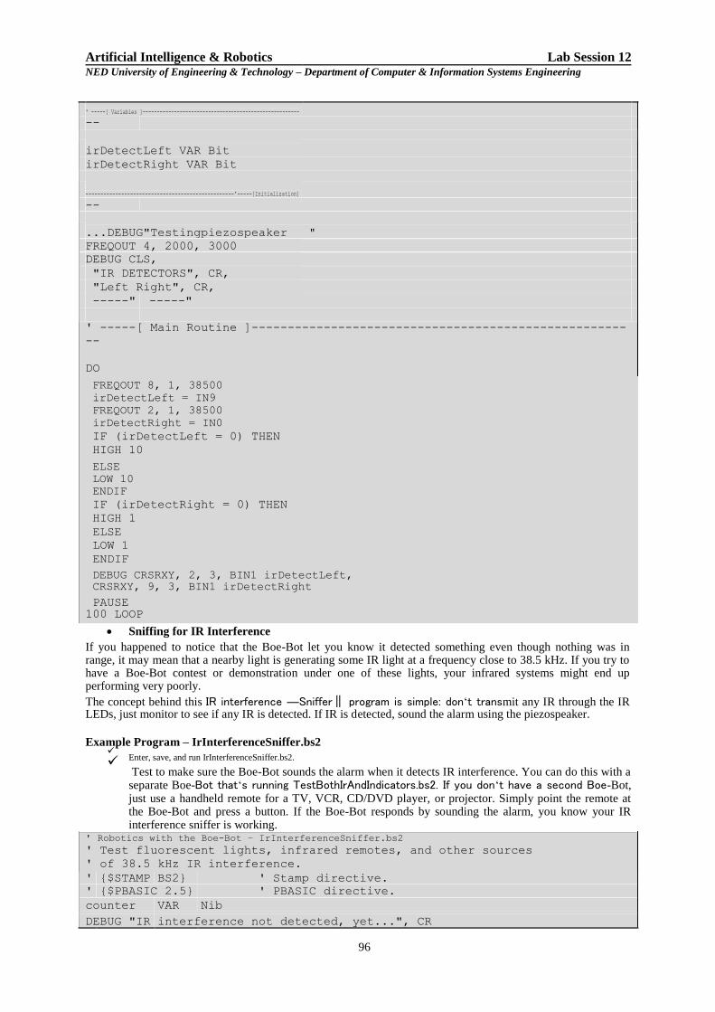
Artificial Intelligence & Robotics Lab Session 12 NED University of Engineering & Technology – Department of Computer & Information Systems Engineering
' -----[ Variables ]-------------------------------------------------------
--
irDetectLeft VAR Bit irDetectRight VAR Bit
--------------------------------------------------'-----[Initialization] --
...DEBUG"Testingpiezospeaker " FREQOUT 4, 2000, 3000
DEBUG CLS,
"IR DETECTORS", CR,
"Left Right", CR,
-----" -----" ' -----[ Main Routine ]---------------------------------------------------- --
DO FREQOUT 8, 1, 38500
irDetectLeft = IN9
FREQOUT 2, 1, 38500
irDetectRight = IN0 IF (irDetectLeft = 0) THEN HIGH 10
ELSE
LOW 10
ENDIF IF (irDetectRight = 0) THEN HIGH 1 ELSE LOW 1 ENDIF
DEBUG CRSRXY, 2, 3, BIN1 irDetectLeft,
CRSRXY, 9, 3, BIN1 irDetectRight PAUSE
100 LOOP Sniffing for IR Interference
If you happened to notice that the Boe-Bot let you know it detected something even though nothing was in range, it may mean that a nearby light is generating some IR light at a frequency close to 38.5 kHz. If you try to have a Boe-Bot contest or demonstration under one of these lights, your infrared systems might end up performing very poorly. The concept behind this IR interference ―Sniffer‖ program is simple: don‘t transmit any IR through the IR LEDs, just monitor to see if any IR is detected. If IR is detected, sound the alarm using the piezospeaker.
Example Program – IrInterferenceSniffer.bs2
Enter, save, and run IrInterferenceSniffer.bs2.
Test to make sure the Boe-Bot sounds the alarm when it detects IR interference. You can do this with a separate Boe-Bot that‘s running TestBothIrAndIndicators.bs2. If you don‘t have a second Boe-Bot, just use a handheld remote for a TV, VCR, CD/DVD player, or projector. Simply point the remote at the Boe-Bot and press a button. If the Boe-Bot responds by sounding the alarm, you know your IR interference sniffer is working.
' Robotics with the Boe-Bot – IrInterferenceSniffer.bs2
' Test fluorescent lights, infrared remotes, and other sources ' of 38.5 kHz IR interference.
' {$STAMP BS2} ' Stamp directive.
' {$PBASIC 2.5} ' PBASIC directive.
counter VAR Nib
DEBUG "IR interference not detected, yet...", CR
96

Artificial Intelligence & Robotics Lab Session 12 NED University of Engineering & Technology – Department of Computer & Information Systems Engineering DO IF (IN0 = 0) OR (IN9 = 0) THEN DEBUG "IR Interference detected!!!", CR FOR counter = 1 TO 5 HIGH 1 HIGH 10
FREQOUT 4, 50, 4000 LOW 1 LOW 10
PAUSE 20 NEXT
ENDIF
LOOP TASK 3: Infrared Detection Range Adjustments You may have noticed that brighter car headlights (or a brighter flashlight) can be used to see objects that are further away when it‘s dark. By making the Boe-Bot‘s infrared LED headlights brighter, you can also increase its detection range. By resisting electric current less, a smaller resistor allows more current to flow through an LED. More current through an LED is what causes it to glow more brightly. In this activity, you will examine the effect of different resistance values with both the red and infrared LEDs.
Parts List You will need some extra parts for this activity. (2) Resistors, 470 Ω (yellow-violet-brown) (2) Resistors, 220 Ω (red-red-brown) (2) Resistors, 2 kΩ (red-black-red) (2) Resistors, 4.7 kΩ (yellow-violet-red)
Series Resistance and LED Brightness First, let‘s use one of the red LEDs to ―see‖ the difference that a resistor makes in how brightly an LED glows. All we need to test the LED is a program that sends a high signal to the LED. Example Program – P1LedHigh.bs2
Enter, save and run P1LedHigh.bs2.
Run the program and verify that the LED in the circuit connected to P1 emits light.
' Robotics with the Boe-Bot - P1LedHigh.bs2 ' Set P1 high to test for LED brightness testing with each of ' these resistor values in turn: 220 ohm , 470 ohm, 1 k ohm. ' {$STAMP BS2} ' {$PBASIC 2.5} DEBUG "Program Running!" HIGH 1 STOP TASK 4: Object Detection and Avoidance An interesting thing about the IR detectors is that their outputs are just like the whiskers. When no object is detected, the output is high; when an object is detected, the output is low. In this activity, RoamingWithWhiskers.bs2 from the previous lab session is modified so that it works with the IR detectors.
Converting the Whiskers Program for IR Object Detection/Avoidance This next example program started as RoamingWithWhiskers.bs2. Aside from adjusting the name and description, two bit variables were added to store the states of the IR detectors. irDetectLeft VAR Bit irDetectRight VAR Bit A routine was also added to read the IR object detectors. FREQOUT 8, 1, 38500
irDetectLeft = IN9
FREQOUT 2, 1, 38500
irDetectRight = IN0 The IF…THEN statements were modified so that they look at the variables that store the IR object detections instead of the whisker inputs. IF (irDetectLeft = 0) AND (irDetectRight = 0) THEN GOSUB Back_Up GOSUB Turn_Left GOSUB Turn_Left ELSEIF (irDetectLeft = 0) THEN GOSUB Back_Up GOSUB Turn_Right
97

Artificial Intelligence & Robotics Lab Session 12 NED University of Engineering & Technology – Department of Computer & Information Systems Engineering
ELSEIF (irDetectRight = 0) THEN GOSUB Back_Up GOSUB Turn_Left ELSE GOSUB Forward_Pulse ENDIF Example Program – RoamingWithIr.bs2
Open RoamingWithWhiskers.bs2
Modify it so that it matches the program below.
Reconnect power to your board and servos.
Save and run it.
Verify that, aside from the fact that there‘s no contact required, it behaves like
RoamingWithWhiskers.bs2.
' -----[ Title ]-------------------------------------------------------------- ' Robotics with the Boe-Bot - RoamingWithIr.bs2 ' Adapt RoamingWithWhiskers.bs2 for use with IR object detectors. ' {$STAMP BS2} ' Stamp directive. ' {$PBASIC 2.5} ' PBASIC directive. DEBUG "Program Running!" ' -----[ Variables ]----------------------------------------------------------
irDetectLeft VAR Bit
irDetectRight VAR Bit
pulseCount VAR Byte
' -----[ Initialization ]----------------------------------------------------- FREQOUT 4, 2000, 3000 ' Signal program start/reset. ' -----[ Main Routine ]------------------------------------------------------- DO
FREQOUT 8, 1, 38500 ' Store IR detection values in irDetectLeft = IN9 ' bit variables. FREQOUT 2, 1, 38500
irDetectRight = IN0 IF (irDetectLeft = 0) AND (irDetectRight = 0) THEN GOSUB Back_Up ' Both detect obstacle GOSUB Turn_Left ' Back up & U-turn (left twice) GOSUB Turn_Left ELSEIF (irDetectLeft = 0) THEN ' Left detects GOSUB Back_Up ' Back up & turn right GOSUB Turn_Right
ELSEIF (irDetectRight = 0) THEN ' Right detects GOSUB Back_Up ' Back up & turn left GOSUB Turn_Left
ELSE ' None detect
GOSUB Forward_Pulse ' Apply a forward pulse ENDIF ' and check again
LOOP
' -----[ Subroutines ]-------------------------------------------------------- Forward_Pulse: ' Send a single forward pulse. PULSOUT 13,850
PULSOUT 12,650
PAUSE 20
RETURN
Turn_Left: ' Left turn, about 90-degrees. FOR pulseCount = 0 TO 20
PULSOUT 13, 650
PULSOUT 12, 650
PAUSE 20 NEXT
RETURN
Turn_Right:
FOR pulseCount = 0 TO 20 ' Right turn, about 90-degrees. PULSOUT 13, 850
PULSOUT 12, 850
PAUSE 20
NEXT
RETURN
Back_Up: ' Back up. FOR pulseCount = 0 TO 40
PULSOUT 13, 650
PULSOUT 12, 850
PAUSE 20
NEXT
RETURN
98

Artificial Intelligence & Robotics Lab Session 12 NED University of Engineering & Technology – Department of Computer & Information Systems Engineering
Introducing the Phototransistor A transistor is like a valve that regulates the amount of electric current that passes through two of its terminals. The third terminal of a transistor controls just how much current passes through the other two. Depending on the type of transistor, the current flow can be controlled by voltage, current, or in the case of the phototransistor, by light. Figure 12-9 shows the schematic and part drawing of the phototransistor in your Boe-Bot Robot kit. The brightness of the light shining on the phototransistor‘s base (B) terminal determines how much current it will allow to pass into its collector (C) terminal, and out through its emitter (E) terminal. Brighter light results in more current; less-bright light results in less current.
Figure 12-9: Phototransistor Schematic Symbol and Part Drawing
Although the phototransistor and LED are different devices, they do have two similarities. First, if you connect the phototransistor in the circuit backwards, it won‘t work right. Second, the phototransistor has two different length pins and a flat spot on its plastic case for identifying its terminals. The longer of the two pins indicates the phototransistor‘s collector terminal, and the shorter pin indicates the emitter. The emitter terminal also connects closer to a flat spot on the phototransistor‘s clear plastic case, which is useful for identifying the terminals if the leads have been trimmed.
Check Figure 12-9 and find the emitter terminal‘s flat spot and shorter pin.
Circuit designs that use phototransistors for light detection can be adjusted to perform better in certain light levels, and the phototransistor circuits in this lab session are designed for indoor use. So if your robotics area has fluorescent, incandescent, or indirect halogen indoor lighting, it should work great. Avoid sunlight streaming in through nearby windows, because it‘ll flood the phototransistors with too much infrared light. Halogen lamps pointed directly at the course could also cause problems. They should only provide indirect light, ideally directed upward so that the light is reflected off the ceiling. For best results, set up your course in an area with bright fluorescent lighting. TASK 1: A Simple Binary Light Sensor Imagine that your Boe-Bot is navigating a course, and that there‘s a bright light at the end. For example, it could be
a bright light pointing down at a certain spot. Your Boe- Bot‘s last task in the course could be to stop underneath
that bright light. Incandescent bulbs in desk lamps and flashlights make the best ―bright light‖ sources. Compact
fluorescent and LED light sources are not as easy for the circuit in this activity to recognize. In this activity, you will learn a simple light - seeking task for the Boe-Bot i.e. stopping the Boe-Bot under a bright light. This circuit lets the BASIC Stamp know it detected bright light with a binary-1, or ambient light with a binary-0.
Parts List (1) Phototransistor (2) Jumper wires (1) Resistor, 220 Ω (red-red-brown) (1) Resistor, 470 Ω (yellow-violet-brown) (1) Resistor, 1 kΩ (brown-black-red) (1) Resistor, 2 kΩ (red-black-red) (1) Resistor, 4.7 kΩ (yellow-violet-red) (1) Resistor, 10 kΩ (brown-black-orange)
99

Artificial Intelligence & Robotics Lab Session 12 NED University of Engineering & Technology – Department of Computer & Information Systems Engineering
Figure 12-10: Phototransistors vs. IR LEDs
Building the Bright Light Detector Figure 12-11 shows the schematic and wiring diagram of a voltage output phototransistor circuit that the BASIC Stamp will use to get that binary 1 or 0 value. After some testing, and depending on the light conditions in your robotics area, you might end up replacing the 2 kΩ resistor with any other resistors in the parts list.
Disconnect power from your board and servos.
Build the circuit shown in Figure 12-11.
The wiring diagram points out the phototransistor emitter pin, which is shorter and closer to the flat spot on the plastic case. Double check you‘re wiring using the figure as a reference to make sure the phototransistor‘s collector and emitter are correctly connected in your light sensing circuits.
Figure 12-11: Phototransistor Voltage Output Circuit (Right) and Wiring Diagram (Left)
Example Program: TestBinaryPhototransistor.bs2 This program should make the Debug Terminal display a value of 0 in a room with fluorescent lights, and no direct sunlight. When you shine a bright light on the phototransistor, the program should display a value of 1. Figure 12-12 shows an example.
100

Artificial Intelligence & Robotics Lab Session 12 NED University of Engineering & Technology – Department of Computer & Information Systems Engineering
Figure 12-12: Debug Terminal Displays TestBinaryPhototransistor.bs2 Messages
Ambient Fluorescent Light(Left),Bright Light(Right)
Make sure the phototransistor leads do not touch each other. Optionally wrap the exposed portions of the leads with electrical tape.
Reconnect power to your board.
Enter, save, and run TestBinaryPhototransistor.bs2.
Watch the value of IN6 in the Debug Terminal, and verify that it stores a 0 when it‘s not under the bright light and a 1 when it‘s under bright light. Good sources of bright light include incandescent flashlights (flashlights with bulbs, not LEDs), incandescent desk lamps, and small halogen lamps.
If the ambient light is brighter than just fluorescent lights, and you have a nice bright lamp, you may
need to replace the 2 kΩ resistor with a smaller value. Try 1 kΩ, 470 Ω, or even 220 Ω for really bright
lights.
If the ambient light is low, and you are using a fluorescent desk lamp bulb or an LED flashlight for your bright light, you may need to change the 2 kΩ resistor to 4.7 kΩ, or even 10 kΩ.
' Robotics with the Boe-Bot - TestBinaryPhototransistor.bs2 ' Display 1 when the phototransistor circuit applies more than 1.4 V to P6 ' or 0 when it applies less than 1.4 V. ' {$STAMP BS2} ' {$PBASIC 2.5} PAUSE 1000 DEBUG CLS DO DEBUG HOME, "IN6 = ", BIN IN6 PAUSE 100 LOOP
Exercise:
1. What is the frequency of the signal sent by FREQOUT 2, 1, 38500? What is the value of the second frequency sent by that command? How long are these signals sent for? What I/O pin does the IR LED circuit have to be connected to in order to broadcast this signal?
_______________________________________________________________________________________ _______________________________________________________________________________________ _______________________________________________________________________________________
2. Modify a line of code in IrInterferenceSniffer.bs2 so that it only monitors one of the IR detectors. _______________________________________________________________________________________
3. Modify RoamingWithIr.bs2 so that the IR object detectors are checked in a subroutine. __________________________________________________________________________________ __________________________________________________________________________________
__________________________________________________________________________________ __________________________________________________________________________________
__________________________________________________________________________________
__________________________________________________________________________________
101

Artificial Intelligence & Robotics Lab Session 12 NED University of Engineering & Technology – Department of Computer & Information Systems Engineering
__________________________________________________________________________________ __________________________________________________________________________________ __________________________________________________________________________________ __________________________________________________________________________________ __________________________________________________________________________________ __________________________________________________________________________________ __________________________________________________________________________________ __________________________________________________________________________________ __________________________________________________________________________________ __________________________________________________________________________________ __________________________________________________________________________________ __________________________________________________________________________________ __________________________________________________________________________________ __________________________________________________________________________________ __________________________________________________________________________________ __________________________________________________________________________________ __________________________________________________________________________________ __________________________________________________________________________________ __________________________________________________________________________________ __________________________________________________________________________________ __________________________________________________________________________________ __________________________________________________________________________________ __________________________________________________________________________________ __________________________________________________________________________________ __________________________________________________________________________________ __________________________________________________________________________________ __________________________________________________________________________________ __________________________________________________________________________________ __________________________________________________________________________________ __________________________________________________________________________________ __________________________________________________________________________________ __________________________________________________________________________________ __________________________________________________________________________________ __________________________________________________________________________________ __________________________________________________________________________________ __________________________________________________________________________________ __________________________________________________________________________________
4. Create a program named HaltUnderBrightLight.bs2 that will make the Boe-Bot go forward until the
phototransistor detects light that‘s bright enough to make IN6 store a binary-1. _______________________________________________________________________________________ __________________________________________________________________________________ _______________________________________________________________________________________ __________________________________________________________________________________ _______________________________________________________________________________________ ___________________________________________________________________________________ _______________________________________________________________________________________ _______________________________________________________________________________________ _______________________________________________________________________________________ __________________________________________________________________________________ _______________________________________________________________________________________ __________________________________________________________________________________
102

Artificial Intelligence & Robotics Lab Session 12 NED University of Engineering & Technology – Department of Computer & Information Systems Engineering
5. Consider the same scenario as in Q.4. What if you will only have a limited time at the course before the competition, and you don‘t know the lighting conditions in advance? You might need to calibrate your Boe- Bot on site. A program that makes the piezospeaker beep repeatedly when the Boe-Bot detects bright light and stay quiet when it detects ambient light could be useful for this task. Write and test the program that works with the circuit in Figure 12-11.
_______________________________________________________________________________________ _________________________________________________________________________________ _______________________________________________________________________________________ _________________________________________________________________________________ _______________________________________________________________________________________ _________________________________________________________________________________ _______________________________________________________________________________________ __________________________________________________________________________________ _______________________________________________________________________________________ _________________________________________________________________________________ _______________________________________________________________________________________ _________________________________________________________________________________ _______________________________________________________________________________________ __________________________________________________________________________________
103

Section Four
Fuzzy Logic
104

Artificial Intelligence and Robotics Lab Session 13 NED University of Engineering & Technology – Department of Computer & Information Systems Engineering
Lab Session 13
OBJECT
Learning MATLAB Fuzzy Logic Toolbox for the development of fuzzy logic
based applications
Introduction
Fuzzy Logic Toolbox™ software is a collection of functions built on the MATLAB® technical computing environment. It provides tools for you to create and edit fuzzy inference systems within the framework of MATLAB. This toolbox relies heavily on graphical user interface (GUI) tools to help you accomplish your work, although you can work entirely from the command line if you prefer. In this lab session, we will use GUI for building fuzzy logic based application.
Fuzzy Inference Systems
Fuzzy inference is the process of formulating the mapping from a given input to an output using fuzzy logic. The mapping then provides a basis from which decisions can be made, or patterns discerned. The process of fuzzy inference involves ―Membership Functions‖, ―Logical Operations‖ , and ― If-Then Rules‖ . Fuzzy inference systems have been successfully applied in fields such as automatic control, data classification, decision analysis, expert systems, and computer vision. Because of its multidisciplinary nature, fuzzy inference systems are associated with a number of names, such as fuzzy-rule-based systems, fuzzy expert systems, fuzzy modeling, fuzzy associative memory, fuzzy logic controllers, and simply (and ambiguously) fuzzy systems. You can implement two types of fuzzy inference systems in the toolbox: Mamdani-type and Sugeno-type. These two types of inference systems vary somewhat in the way outputs are determined. Mamdani-type inference, as defined for the toolbox, expects the output membership functions to be fuzzy sets. After the aggregation process there is a fuzzy set for each output variable that needs defuzzification. It is possible, and in many cases much more efficient, to use a single spike as the output membership function rather than a distributed fuzzy set. This type of output is sometimes known as a singleton output membership function, and it can be thought of as a pre-defuzzified fuzzy set. It enhances the efficiency of the defuzzification process because it greatly simplifies the computation required by the more general Mamdani method, which finds the centroid of a two-dimensional function. Rather than integrating across the two-dimensional function to find the centroid, you use the weighted average of a few data points. Sugeno-type systems support this type of model. In general, Sugeno-type systems can be used to model any inference system in which the output membership functions are either linear or constant.
Overview of Fuzzy Inference Process
We‘ll start with a basic description of a two-input, one-output tipping problem (based on tipping practices in the United States).
105

Artificial Intelligence and Robotics Lab Session 13 NED University of Engineering & Technology – Department of Computer & Information Systems Engineering The Basic Tipping Problem
Given a number between 0 and 10 that represents the quality of service at a restaurant (where 10 is excellent), and another number between 0 and 10 that represents the quality of the food at that restaurant (again, 10 is excellent), what should the tip be?
The starting point is to write down the three golden rules of tipping.
1. If the service is poor or the food is rancid, then tip is cheap.
2. If the service is good, then tip is average.
3. If the service is excellent or the food is delicious, then tip is generous. Assume that an average tip is 15%, a generous tip is 25%, and a cheap tip is 5%.
Now that you know the rules and have an idea of what the output should look like, begin working with the GUI tools to construct a fuzzy inference system for this decision process.
The FIS Editor
The FIS Editor displays information about a fuzzy inference system. To open the FIS Editor, type the following command at the MATLAB prompt: fuzzy
The generic untitled FIS Editor opens, with one input labeled input1, and one output labeled output1.
In the given example, you construct a two-input, one output system. The two inputs are service and food. The one output is tip. To add a second input variable and change the variable names to reflect these designations:
1. Select Edit > Add variable > Input.
A second yellow box labeled input2 appears.
2. Click the yellow box input1. This box is highlighted with a red outline.
3. Edit the Name field from input1 to service, and press Enter.
4. Click the yellow box input2. This box is highlighted with a red outline.
5. Edit the Name field from input2 to food, and press Enter.
6. Click the blue box output1.
7. Edit the Name field from output1 to tip, and press Enter.
8. Select File > Export > To Workspace.
9. Enter the Workspace variable name tipper, and click OK.
The diagram is updated to reflect the new names of the input and output variables. There is now a new variable in the workspace called tipper that contains all the information about this system. By saving to the workspace with a new name, you also rename the entire system. Your window looks something like the following diagram.
Leave the inference options in the lower left in their default positions for now. You have entered all the information you need for this particular GUI. Next, define the membership functions associated with each of the variables. To do this, open the Membership Function Editor. You can open the Membership Function Editor in one of three ways:
• Within the FIS Editor window, select Edit > Membership Functions.
• Within the FIS Editor window, double-click the blue icon called tip.
106

Artificial Intelligence and Robotics Lab Session 13 NED University of Engineering & Technology – Department of Computer & Information Systems Engineering
• At the command line, type mfedit.
Figure 13.1
The Membership Function Editor
The Membership Function Editor is the tool that lets you display and edit all of the membership functions associated with all of the input and output variables for the entire fuzzy inference system. The Membership Function Editor shares some features with the FIS Editor, as shown in Figure 2. In fact, all of the five basic GUI tools have similar menu options, status lines, and Help and Close buttons.
Figure 13.2
107

Artificial Intelligence and Robotics Lab Session 13 NED University of Engineering & Technology – Department of Computer & Information Systems Engineering
Figure 13.3
When you open the Membership Function Editor to work on a fuzzy inference system that does not already exist in the workspace, there is no membership function associated with the variables that you defined with the FIS Editor. On the upper-left side of the graph area in the Membership Function Editor is a ―Variable Palette‖ that lets you set the membership functions for a given variable. To set up the membership functions associated with an input or an output variable for the FIS, select a FIS variable in this region by clicking it. Next select the Edit pull-down menu, and choose Add MFs... A new window appears which allows you to select both the membership function type and the number of membership functions associated with the selected variable.
In the lower-right corner of the window are the controls that let you change the name, type, and parameters (shape), of the membership function, after it is selected.
The membership functions from the current variable are displayed in the main graph. These membership functions can be manipulated in two ways. You can first use the mouse to select a particular membership function associated with a given variable quality, (such as poor, for the variable, service), and then drag the membership function from side to side.
The process of specifying the membership functions for the two input tipping example, tipper, is as follows:
1. Double-click the input variable service to open the Membership Function Editor. 2. In the Membership Function Editor, enter [0 10] in the Range and the Display Range
fields. 3. Create membership functions for the input variable service.
a. Select Edit > Remove All MFs to remove the default membership functions for the input variable service.
b. Select Edit > Add MFs. to open the Membership Functions dialog box.
c. In the Membership Functions dialog box, select gaussmf as the MF Type. d. Verify that 3 is selected as the Number of MFs.
e. Click OK to add three Gaussian curves to the input variable service. 4. Rename the membership functions for the input variable service, and specify their
parameters. a. Click on the curve named mf1 to select it, and specify the following fields in the
Current Membership Function (click on MF to select) area: • In the Name field, enter poor.
• In the Params field, enter [1.5 0].
108

Artificial Intelligence and Robotics Lab Session 13 NED University of Engineering & Technology – Department of Computer & Information Systems Engineering
Figure 13.4
The two inputs of Params represent the standard deviation and center for the Gaussian curve. Tip to adjust the shape of the membership function, type in desired parameters.
b. Click on the curve named mf2 to select it, and specify the following fields in the
Current Membership Function (click on MF to select) area:
• In the Name field, enter good. • In the Params field, enter [1.5 5].
c. Click on the curve named mf3, and specify the following fields in the Current
Membership Function (click on MF to select) area: • In the Name field, enter excellent.
• In the Params field, enter [1.5 10].
5. In the FIS Variables area, click the input variable food to select it.
6. Enter [0 10] in the Range and the Display Range fields. 7. Create the membership functions for the input variable food.
a. Select Edit > Remove All MFs to remove the default Membership Functions for the input variable food.
b. Select Edit > Add MFs to open the Membership Functions dialog box.
c. In the Membership Functions dialog box, select trapmf as the MF Type. d. Select 2 in the Number of MFs drop-down list.
e. Click OK to add two trapezoidal curves to the input variable food.
109

Artificial Intelligence and Robotics Lab Session 13 NED University of Engineering & Technology – Department of Computer & Information Systems Engineering 8. Rename the membership functions for the input variable food, and specify their parameters:
a. In the FIS Variables area, click the input variable food to select it.
b. Click on the curve named mf1, and specify the following fields in the Current Membership Function (click on MF to select) area:
• In the Name field, enter rancid.
• In the Params field, enter [0 0 1 3].
c. Click on the curve named mf2 to select it, and enter delicious in the Name field.
d. Reset the associated parameters if desired.
9. Click on the output variable tip to select it. 10. Enter [0 30] in the Range and the Display Range fields to cover the output range. The
input ranges from 0 to 10, but the output is a tip between 5% and 25%. 11. Rename the default triangular membership functions for the output variable tip, and
specify their parameters. a. Click the curve named mf1 to select it, and specify the following fields in the
Current Membership Function (click on MF to select) area:
• In the Name field, enter cheap. • In the Params field, enter [0 5 10].
b. Click the curve named mf2 to select it, and specify the following fields in the
Current Membership Function (click on MF to select) area:
• In the Name field, enter average. • In the Params field, enter [10 15 20].
c. Click the curve named mf3 to select it, and specify the following:
• In the Name field, enter generous.
• In the Params field, enter [20 25 30]. Now that the variables have been named and the membership functions have appropriate shapes and names, you can enter the rules. To call up the Rule Editor, go to the Edit menu and select Rules, or type ruleedit at the command line.
Constructing rules using the graphical Rule Editor interface is fairly self evident. Based on the descriptions of the input and output variables defined with the FIS Editor, the Rule Editor allows you to construct the rule statements automatically, From the GUI, you can create rules by selecting an item in each input and output variable box, selecting one Connection item, and clicking Add Rule. You can choose none as one of the variable qualities to exclude that variable from a given rule and choose not under any variable name to negate the associated quality.
• Delete a rule by selecting the rule and clicking Delete Rule.
• Edit a rule by changing the selection in the variable box and clicking Change Rule.
• Specify weight to a rule by typing in a desired number between 0 and 1 in Weight. If you do not specify the weight, it is assumed to be unity (1).
To insert the first rule in the Rule Editor, select the following:
• poor under the variable service
• rancid under the variable food • The or radio button, in the Connection block
• cheap, under the output variable, tip. Then, click Add rule.
110

Artificial Intelligence and Robotics Lab Session 13 NED University of Engineering & Technology – Department of Computer & Information Systems Engineering The resulting rule is
1. If (service is poor) or (food is rancid) then (tip is cheap) (1)
The numbers in the parentheses represent weights.
Follow a similar procedure to insert the second and third rules in the Rule Editor to get:
1. If (service is poor) or (food is rancid) then (tip is cheap) (1)
2. If (service is good) then (tip is average) (1)
3. If (service is excellent) or (food is delicious) then (tip is generous) (1)
At this point, the fuzzy inference system has been completely defined, in that the variables, membership functions, and the rules necessary to calculate tips are in place. Now, look at the fuzzy inference diagram presented at the end of the previous section and verify that everything is behaving the way you think it should. You can use the Rule Viewer, the next of the GUI tools we‘ll look at. From the View menu, select Rules.
The Rule Viewer
The Rule Viewer displays a roadmap of the whole fuzzy inference process. It is based on the fuzzy inference diagram described in the previous section. You see a single figure window (Figure 5) with 10 plots nested in it. The three plots across the top of the figure represent the antecedent and consequent of the first rule. Each rule is a row of plots, and each column is a variable. The rule numbers are displayed on the left of each row. You can click on a rule number to view the rule in the status line.
The first two columns of plots (the six yellow plots) show the membership functions
referenced by the antecedent, or the if-part of each rule. The third column of plots (the three blue plots) shows the membership functions referenced
by the consequent, or the then-part of each rule.
Notice that under food, there is a plot which is blank. This corresponds to the characterization of none for the variable food in the second rule.
The fourth plot in the third column of plots represents the aggregate weighted decision for the given inference system. This decision will depend on the input values for the system. The defuzzified output is displayed as a bold vertical line on this plot. The variables and their current values are displayed on top of the columns. In the lower left, there is a text field Input in which you can enter specific input values. For the two-input system, you will
enter an input vector, [9 8], for example, and then press Enter. You can also adjust these
input values by clicking on any of the three plots for each input. This will move the red index line horizontally, to the point where you have clicked. Alternatively, you can also click and drag this line in order to change the input values. When you release the line, (or after manually specifying the input), a new calculation is performed, and you can see the whole fuzzy inference process take place.
111

Artificial Intelligence and Robotics Lab Session 13 NED University of Engineering & Technology – Department of Computer & Information Systems Engineering
Figure 13.5
Where the index line representing service crosses the membership function line ―service
is poor‖ in the upper-left plot determines the degree to which rule one is activated.
A yellow patch of color under the actual membership function curve is used to make the
fuzzy membership value visually apparent. Each of the characterizations of each of the variables is specified with respect to the input index line in this manner. If you follow rule 1 across the top of the diagram, you can see the consequent ―tip is cheap‖ has been truncated to exactly the same degree as the (composite) antecedent—this is the implication process in action. The aggregation occurs down the third column, and the resultant aggregate plot is shown in the single plot appearing in the lower right corner of the
plot field. The defuzzified output value is shown by the thick line passing through the aggregate fuzzy set. You can shift the plots using left, right, down, and up. The menu items allow you to save, open, or edit a fuzzy system using any of the five basic GUI tools.
The Rule Viewer allows you to interpret the entire fuzzy inference process at once. The Rule Viewer also shows how the shape of certain membership functions influences the overall result. Because it plots every part of every rule, it can become unwieldy for particularly large systems, but, for a relatively small number of inputs and outputs, it performs well (depending on how much screen space you devote to it) with up to 30 rules and as many as 6 or 7 variables.
112

Artificial Intelligence and Robotics Lab Session 13 NED University of Engineering & Technology – Department of Computer & Information Systems Engineering When you save a fuzzy system to a file, you are saving an ASCII text FIS file representation of that system with the file suffix .fis. This text file can be edited and modified and is simple to understand. When you save your fuzzy system to the MATLAB workspace, you are creating a variable (whose name you choose) that acts as a MATLAB structure for the FIS system. FIS files and FIS structures represent the same system.
If you do not save your FIS to a file, but only save it to the MATLAB workspace, you cannot recover it for use in a new MATLAB session.
EXERCISES
1) Implement the following rule set in matlab, to control the mechanism of a crane.
IF Distance is far AND Angle is zero THEN apply pos_medium Power
IF Distance is far AND Angle is neg_small THEN apply pos_high Power
IF Distance is medium AND Angle is neg_small THEN apply pos_high Power
IF Distance is medium AND Angle is neg_big THEN apply pos_medium Power
IF Distance is close AND Angle is pos_small THEN apply neg_medium Power IF Distance is close AND Angle is neg_small THEN apply pos_medium Power
IF Distance is close AND Angle is zero THEN apply zero Power
IF Distance is zero AND Angle is zero THEN apply zero Power
IF Distance is zero AND Angle is pos_small THEN apply neg_medium Power
Develop a fuzzy logic based application of your choice.
2) Attach the screenshots of FIS editor, membership functions of all input & output
parameters, rule editor and rule viewer.
113

Artificial Intelligence and Robotics Lab Session 13 NED University of Engineering & Technology – Department of Computer & Information Systems Engineering 3) Implement the following rule set in matlab, to control the mechanism of a fuzzy logic
based washing machine.
If clothe material is soft and status is clean then apply low power for less cycle time.
If clothe material is soft and status is dirty then apply low power for long cycle
time.
If clothe material is medium and status is dirty then apply medium power for long cycle time.
If clothe material is hard and status is clean then apply medium power for long
cycle time.
If clothe material is hard and status is dirty then apply high power for long cycle time.
4) Attach the screenshots of FIS editor, membership functions of all input & output
parameters, rule editor and rule viewer.
114
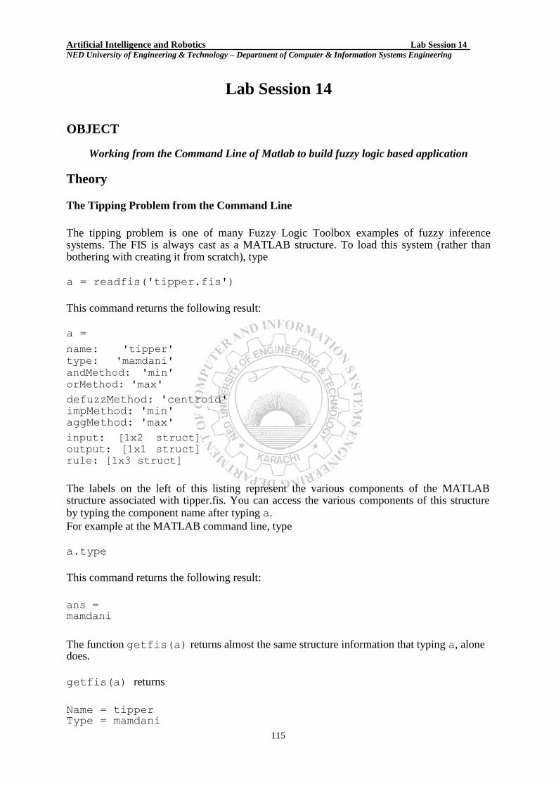
Artificial Intelligence and Robotics Lab Session 14 NED University of Engineering & Technology – Department of Computer & Information Systems Engineering
Lab Session 14
OBJECT
Working from the Command Line of Matlab to build fuzzy logic based application
Theory
The Tipping Problem from the Command Line
The tipping problem is one of many Fuzzy Logic Toolbox examples of fuzzy inference systems. The FIS is always cast as a MATLAB structure. To load this system (rather than bothering with creating it from scratch), type a = readfis('tipper.fis')
This command returns the following result: a = name: 'tipper'
type: 'mamdani'
andMethod: 'min'
orMethod: 'max' defuzzMethod: 'centroid'
impMethod: 'min'
aggMethod: 'max' input: [1x2 struct]
output: [1x1 struct]
rule: [1x3 struct]
The labels on the left of this listing represent the various components of the MATLAB structure associated with tipper.fis. You can access the various components of this structure by typing the component name after typing a. For example at the MATLAB command line, type a.type
This command returns the following result:
ans =
mamdani
The function getfis(a) returns almost the same structure information that typing a, alone does.
getfis(a) returns
Name = tipper Type = mamdani
115

Artificial Intelligence and Robotics Lab Session 14 NED University of Engineering & Technology – Department of Computer & Information Systems Engineering NumInputs = 2
InLabels =
service food
NumOutputs = 1
OutLabels =
tip NumRules = 3
AndMethod = min
OrMethod = max
ImpMethod = min
AggMethod = max DefuzzMethod = centroid
Some of these fields are not part of the structure, a. Thus, you cannot get information by typing a.Inlabels, but you can get it by typing getfis(a,'Inlabels')
Similarly, you can obtain structure information using getfis in this manner.
getfis(a,'input',1) getfis(a,'output',1) getfis(a,'input',1,'mf',1)
The structure.field syntax also generates this information. For example, type a.input
or a.input(1).mf(1)
The function setfis acts as the reciprocal to getfis. It allows you to change any property
of a FIS. For example, if you wanted to change the name of this system, you could type a = setfis(a,'name','gratuity');
However, because a is already a MATLAB structure, you can set this information more simply by typing a.name = 'gratuity';
Now the FIS structure a has been changed to reflect the new name. If you want a little more insight into this FIS structure, try showfis(a)
116

Artificial Intelligence and Robotics Lab Session 14 NED University of Engineering & Technology – Department of Computer & Information Systems Engineering
This syntax returns a printout listing all the information about a. This function is intended more for debugging than anything else, but it shows all the information recorded in the FIS
structure. Because the variable, a, designates the fuzzy tipping system, you can display any of the GUIs for the tipping system directly from the command line. Any of the following functions will display the tipping system with the associated GUI:
• fuzzy(a) displays the FIS Editor. • mfedit(a) displays the Membership Function Editor.
• ruleedit(a) displays the Rule Editor. • ruleview(a) displays the Rule Viewer.
• surfview(a) displays the Surface Viewer.
Building a System from Scratch
You can build a fuzzy inference system using Fuzzy Logic Toolbox commands as an alternative to the GUI tools. For instance, to build the tipping system entirely from the
command line, you use the commands newfis, addvar, addmf, and addrule. Each
variable, input, or output, has an index number, and each membership function has an index number. The rules are built from statements such as the following:
If input1 is MF1 or input2 is MF3, then output1 is MF2 (weight = 0.5)
This rule is turned into a structure according to the following logic. If there are m inputs to a system and n outputs, then the first m vector entries of the rule structure correspond to inputs 1 through m. • The entry in column 1 is the index number for the membership function associated with input 1. • The entry in column 2 is the index number for the membership function associated with input 2, and so on. • The next n columns work the same way for the outputs. • Column m + n + 1 is the weight associated with that rule (typically 1) and column m + n + 2 specifies the connective used (where AND = 1 and OR = 2). The structure associated with the preceding rule is 1 3 2 0.5 2 This sample code shows one way you can build the entire tipping system from the command line, using the MATLAB structure syntax.
a=newfis('tipper');
a.input(1).name='service';
a.input(1).range=[0 10];
a.input(1).mf(1).name='poor';
a.input(1).mf(1).type='gaussmf';
a.input(1).mf(1).params=[1.5 0];
a.input(1).mf(2).name='good';
a.input(1).mf(2).type='gaussmf';
a.input(1).mf(2).params=[1.5 5];
a.input(1).mf(3).name='excellent';
a.input(1).mf(3).type='gaussmf';
a.input(1).mf(3).params=[1.5 10];
a.input(2).name='food';
a.input(2).range=[0 10];
117

Artificial Intelligence and Robotics Lab Session 14 NED University of Engineering & Technology – Department of Computer & Information Systems Engineering a.input(2).mf(1).name='rancid';
a.input(2).mf(1).type='trapmf';
a.input(2).mf(1).params=[-2 0 1 3];
a.input(2).mf(2).name='delicious';
a.input(2).mf(2).type='trapmf';
a.input(2).mf(2).params=[7 9 10 12];
a.output(1).name='tip';
a.output(1).range=[0 30];
a.output(1).mf(1).name='cheap'
a.output(1).mf(1).type='trimf';
a.output(1).mf(1).params=[0 5 10];
a.output(1).mf(2).name='average';
a.output(1).mf(2).type='trimf';
a.output(1).mf(2).params=[10 15 20];
a.output(1).mf(3).name='generous';
a.output(1).mf(3).type='trimf';
a.output(1).mf(3).params=[20 25 30];
a.rule(1).antecedent=[1 1];
a.rule(1).consequent=[1];
a.rule(1).weight=1;
a.rule(1).connection=2;
a.rule(2).antecedent=[2 0];
a.rule(2).consequent=[2];
a.rule(2).weight=1;
a.rule(2).connection=1;
a.rule(3).antecedent=[3 2];
a.rule(3).consequent=[3];
a.rule(3).weight=1;
a.rule(3).connection=2
Alternatively, you can build the entire tipping system from the command line using Fuzzy Logic Toolbox commands. These commands are in the mktipper.m demo file.
a=newfis('tipper');
a=addvar(a,'input','service',[0 10]);
a=addmf(a,'input',1,'poor','gaussmf',[1.5 0]);
a=addmf(a,'input',1,'good','gaussmf',[1.5 5]); a=addmf(a,'input',1,'excellent','gaussmf',[1.5 10]);
a=addvar(a,'input','food',[0 10]);
a=addmf(a,'input',2,'rancid','trapmf',[-2 0 1 3]);
a=addmf(a,'input',2,'delicious','trapmf',[7 9 10 12]);
a=addvar(a,'output','tip',[0 30]);
a=addmf(a,'output',1,'cheap','trimf',[0 5 10]);
a=addmf(a,'output',1,'average','trimf',[10 15 20]);
a=addmf(a,'output',1,'generous','trimf',[20 25 30]);
ruleList=[ ... 1 1 1 1 2 2 0 2 1 1 3 2 3 1 2 ];
a=addrule(a,ruleList);
118

Artificial Intelligence and Robotics Lab Session 14 NED University of Engineering & Technology – Department of Computer & Information Systems Engineering Specifying Custom Membership and Inference Functions
To include a custom membership function, specify the name of the custom membership function, as shown in the following example: a=addmf(a,'input',1,'customMF1','custmf1',[0 1 2 4 6 8 9 10]);
To include a custom inference function, specify the name of the custom inference function, as shown in the following example: a.defuzzMethod='customdefuzz';
FIS Evaluation
To evaluate the output of a fuzzy system for a given input, use the function evalfis. For example, the following script evaluates tipper at the input, [1 2]. a = readfis('tipper'); evalfis([1 2], a) ans =
5.5586
This function can also be used for multiple collections of inputs, because different input vectors are represented in different parts of the input structure.
evalfis([3 5; 2 7], a) ans = 12.2184 7.7885
The FIS Structure
The FIS structure is the MATLAB object that contains all the fuzzy inference system information. This structure is stored inside each GUI tool. Access functions such as getfis
and setfis make it easy to examine this structure. All the information for a given fuzzy inference system is contained in the FIS structure, including variable names, membership function definitions, and so on. You can generate a
listing of information on the FIS using the showfis command, as shown in the following code sample: showfis(a)
1. Name tipper 2. Type mamdani
3. Inputs/Outputs [ 2 1 ] 4. NumInputMFs [ 3 2 ] 5. NumOutputMFs 3
6. NumRules 3 7. AndMethod min 8. OrMethod max
119

Artificial Intelligence and Robotics Lab Session 14 NED University of Engineering & Technology – Department of Computer & Information Systems Engineering
9. ImpMethod min
10. AggMethod max 11. DefuzzMethod centroid 12. InLabels service
13. food 14. OutLabels tip 15. InRange [ 0 10 ] 16. [ 0 10 ]
17. OutRange [ 0 30 ] 18. InMFLabels poor 19. good
20. excellent 21. rancid
22. delicious 23. OutMFLabels cheap
24. average 25. generous 26. InMFTypes gaussmf
27. gaussmf 28. gaussmf 29. trapmf 30. trapmf
31. OutMFTypes trimf 32. trimf 33. trimf
34. InMFParams [ 1.5 0 0 0 ] 35. [ 1.5 5 0 0 ] 36. [ 1.5 10 0 0 ] 37. [ 0 0 1 3 ]
38. [ 7 9 10 10 ] 39. OutMFParams [ 0 5 10 0 ] 40. [ 10 15 20 0 ] 41. [ 20 25 30 0 ]
42. Rule Antecedent [ 1 1 ] 43. [ 2 0 ] 44. [ 3 2 ]
42. Rule Consequent 1 43. 2 44. 3 42. Rule Weight 1
43. 1 44. 1 42. Rule Connection 2
43. 1 44. 2
The list of command-line functions associated with FIS construction includes getfis, setfis, showfis, addvar, addmf, addrule, rmvar, and rmmf.
120

Artificial Intelligence and Robotics Lab Session 14 NED University of Engineering & Technology – Department of Computer & Information Systems Engineering Saving FIS Files
A specialized text file format is used for saving fuzzy inference systems. The functions readfis
and writefis are used for reading and writing these files. If you prefer, you can modify the
FIS by editing its .fis text file rather than using any of the GUIs. You should be aware;
however, that changing one entry may oblige you to change another. For example, if you delete a membership function using this method, you also need to make certain that any rules requiring this membership function are also deleted. The rules appear in indexed format in a .fis text file. The following sample shows the file tipper.fis.
[System] Name='tipper' Type='mamdani' NumInputs=2 NumOutputs=1 NumRules=3 AndMethod='min' OrMethod='max' ImpMethod='min' AggMethod='max' DefuzzMethod='centroid' [Input1] Name='service'
Range=[0 10]
NumMFs=3 MF1='poor':'gaussmf',[1.5 0]
MF2='good':'gaussmf',[1.5 5]
MF3='excellent':'gaussmf',[1.5 10]
[Input2] Name='food' Range=[0 10] NumMFs=2 MF1='rancid':'trapmf',[0 0 1 3]
MF2='delicious':'trapmf',[7 9 10
10] [Output1] Name='tip' Range=[0 30]
NumMFs=3 MF1='cheap':'trimf',[0 5 10]
MF2='average':'trimf',[10 15 20]
MF3='generous':'trimf',[20 25 30]
[Rules] 1 1, 1 (1) : 2 2 0, 2 (1) : 1 3 2, 3 (1) : 2
121

Artificial Intelligence and Robotics Lab Session 14 NED University of Engineering & Technology – Department of Computer & Information Systems Engineering
EXERCISES
1) Develop a fuzzy logic based application for given rule set;
If test marks are bad and performance is bad then sessional marks are poor.
If test marks are bad and performance is average then sessional marks are poor. If test marks are average and performance is average then sessional marks are average.
If test marks are good and performance is excellent then sessional marks are good.
If test marks are excellent and performance is bad then sessional marks are
excellent. Using
a) Fuzzy Logic Toolbox commands.
b) Matlab Structure syntax.
SOLUTION
________________________________________________________________
________________________________________________________________ ________________________________________________________________
________________________________________________________________ ________________________________________________________________
________________________________________________________________ ________________________________________________________________
________________________________________________________________ ________________________________________________________________
________________________________________________________________ ________________________________________________________________
________________________________________________________________ ________________________________________________________________
________________________________________________________________
____________________________________________________________
____________________________________________________________
____________________________________________________________
____________________________________________________________
____________________________________________________________ ____________________________________________________________
____________________________________________________________
____________________________________________________________ ____________________________________________________________
____________________________________________________________
____________________________________________________________ ____________________________________________________________ ____________________________________________________________
____________________________________________________________
122

Artificial Intelligence and Robotics Lab Session 14 NED University of Engineering & Technology – Department of Computer & Information Systems Engineering
____________________________________________________________
____________________________________________________________
____________________________________________________________
____________________________________________________________ ____________________________________________________________
____________________________________________________________
____________________________________________________________ ____________________________________________________________ ____________________________________________________________
____________________________________________________________
____________________________________________________________
____________________________________________________________
____________________________________________________________
____________________________________________________________
____________________________________________________________
____________________________________________________________ ____________________________________________________________
____________________________________________________________
____________________________________________________________
____________________________________________________________ ____________________________________________________________
____________________________________________________________
____________________________________________________________
____________________________________________________________
____________________________________________________________
____________________________________________________________
____________________________________________________________
____________________________________________________________
____________________________________________________________
____________________________________________________________ ____________________________________________________________
____________________________________________________________
____________________________________________________________
____________________________________________________________
____________________________________________________________ ____________________________________________________________
____________________________________________________________
____________________________________________________________ ____________________________________________________________ ____________________________________________________________
123

Artificial Intelligence and Robotics Lab Session 15 NED University of Engineering & Technology – Department of Computer & Information Systems Engineering
Lab Session 15
OBJECT
Learning FuzzyTech for the development of fuzzy logic based applications.
Treeview
The fuzzyTECH provides an overview of all objects (variables, rule blocks and text) in the project and shows the hierarchies of them. This is especially useful for editing these objects. Double-clicking the project title or the symbol aside shows or hides the project structure. Double-clinking an object shows its components, such as all terms of a variable, all rule blocks and text objects. Treeview provides an overview of the hierarchy of project objects than the relations between them (See figure 1).
<Project Title> Input, Output, Intermediate Variables of the project variable mentioned above the variables belonging to it are listed with their names)
<Name of Terms> (all terms of a variable are listed with their names underneath this variable)
<Name of Terms> (all terms of a variable are listed with their names underneath this variable) Rule Blocks of the project
<Rule Block Name> (all rule blocks of the project are listed underneath the entry Rule Blocks with their names)
RB-Inputs and RB-Outputs (each rule block has a subgroup of RB Inputs/RB Outputs)
<Names of the Inputs / Outputs> of the respective rule block are listed Text of the project
<Text Name> (all text objects of the project are listet with their names) Debug Mode (the currently activated debug mode is shown)
Transfer Plot, 3d Plot, Time Plot (underneath these analyzer groups all the analyzers open in the project are listed with their plot number)
Figure 15.1
Fuzzy Design Wizard The Fuzzy Design Wizard (FDW) invokes a sequence of dialogs that guide you to create a complete fuzzy logic prototype. The FDW can also be used to modify an existing fuzzy project. The Fuzzy Design Wizard consists of the following dialogs: Welcome Dialog for specifying the kind of project generation. Number of Variables for determining the quantity of variables (input, output and intermediate) and the number of terms, in which each variable is broken. Define Defuzzification lets you specify the characteristic of the Defuzzification Method. Define Rule Blocks Dialog for the rule configuration of each rule block. Project Editor
This window is created upon start-up of fuzzyTECH and may only be iconized and not closed. Three object types are used in the window:
124

Artificial Intelligence and Robotics Lab Session 15 NED University of Engineering & Technology – Department of Computer & Information Systems Engineering 1. Text To make a fuzzy logic system structure more transparent, text can be inserted at every place in the worksheet. Text objects can be printed in different font sizes, styles and colors. 2. Variables
Each input or output variable of the system is linked with an interface. Interfaces are displayed as small boxes showing a variable name and an icon representing the chosen computation method. Input interfaces show the icon on the left side and output interfaces on the right. Intermediate Variables are not linked with an interface and occur thus only in the rule block they belong to.
3. Rule Blocks In fuzzyTECH, individual rules are confined into rule blocks to build the system structure. A rule block consists of two variable columns and two operator boxes.
The left column shows the variables used in the precondition of fuzzy rules.
The right column shows the variables used for the conclusion of fuzzy rules.
The upper box displays the Condition Aggregation Operator.
The lower box shows the Result Aggregation Operator. Information flow between the linguistic variables is indicated by the lines connecting the different object.
Linguistic Variable Wizard The Variables Wizard consists of a sequence of dialogs that guide you through the definition of a linguistic variable. In Define linguistic Variable basic items of the variable are defined, like name, type (input, output or intermediate) and input/output interfaces. Base Variable Range lets you specify range, default value, and name of the base variable. For the variable range, two different representations exist: the Shell representation (used for all editors) and the Code representation (used in generated code). In MBF Definition membership functions (MBF) of the linguistic variables can be defined. Comments for Variable dialog lets you add comments to the defined variable to provide your project with some additional information.
Rule Block Wizard The Rule Block Wizard invokes a sequence of dialogs that guide through the definition of a rule block and its rules. Define Rule Block Configuration This rule block configuration dialog lets you name the rule block, select the input variables as conditions and the output variables as consequences of the rules of the rule block. Define Rule Block Operators This rule block configuration dialog lets you define a fuzzy operator for the rule block. To determine the inference methods of the rule block, an aggregation operator and a Result Aggregation Operator must be specified. The fuzzy inference consists of three computational steps: Aggregation, Composition, and Result Aggregation. 1. Input Aggregation
125

Artificial Intelligence and Robotics Lab Session 15 NED University of Engineering & Technology – Department of Computer & Information Systems Engineering The input aggregation is the first step of the Fuzzy Rule Inference and determines the degree to which the complete IF-part of the rule is fulfilled. Operators Three families of compensatory operators are available for fuzzy rule computation. These are: Operator Computation MIN-MAX MIN-MAX = (1-GAMMA) * Min (μ i) + GAMMA * MAX (μ i) MIN-AVG MIN-AVG = (1-GAMMA) * Min (μ i) + GAMMA * Sum (μ i)/i GAMA GAMA = Prod (1-GAMMA) * Min (μ i) + GAMMA * MAX (μ i) Non-compensatory operators like MIN, MAX PROD and AVG can be chosen by setting GAMMA to specific values. Parameter To parameterize an operator family, the scroll bar is used. The resulting operator for some parameter values will be an exception, such as:
MIN-MAX with a parameter of 0 = minimum operator (MIN).
MIN-AVG with a parameter of 1 = maximum operator (MAX).
GAMMA with a parameter of 0 = product operator (PROD).
2. Composition The composition operator is PROD only, and cannot be changed. 3. Result-Aggregation The complete definition of a rule block requires determining an operator for result aggregation. FuzzyTECH supports following two methods for result aggregation. MAX: Selects the maximum firing degree of all rules matching to the term. BSUM: Uses a bounded sum. Thus, all firing degrees are summed by using a bound of one.
Define Variable Influence This dialog lets you define a basic set of fuzzy rules that represent the influence between the selected input and output variables. For each pair of input and output variable, the rule block wizard lets you specify the influence from an interval [very negative, negative not at all, positive, very positive].
Spreadsheet Rule Editor
In fuzzyTECH, the rules of each rule block can be edited as spreadsheet. Each row in the Spreadsheet Editor window represents a single fuzzy logic rule or more, with its inputs (conditions) on the left side and its outputs (consequences) on the right side (See figure 2). If the rule block has more than one output, more than one fuzzy logic rules can be contained in a row. The input columns of all rules are titled with the [IF] button, the output columns and the DoS columns are headed by the [THEN] button. For every consequence variable, an additional column [DoS] (Degree of Support) indicates an individual weight for the output variable. A rule with a degree of support of 0 is functionally equal to a non-existent rule. In the left upper corner, additional buttons open the access on special function.
126

Artificial Intelligence and Robotics Lab Session 15 NED University of Engineering & Technology – Department of Computer & Information Systems Engineering
Figure 15.2
Matrix Rule Editor
In fuzzyTECH, rule blocks can be displayed and edited as matrixes, rendering even large rule blocks transparent.
Figure 15.3 Rule Matrix The rule matrix is displayed in the upper left part of the rule editor window showing the relation between two linguistic variables (See Figure 3). Each individual rule maps to field in the matrix. The active rule in the matrix is indicated by a red frame and is also shown in the list boxes in the lower part of the window. Defining Rules Each white field in the matrix represents a single rule and each black field represents a non-defined rule. Individual rules can be chosen by clicking on a matrix field or by selection them from the list boxes. Degree of Support (DoS) The DoS are shown in the Matrix and can be changed by using the scroll bar or the edit field right next to the scroll bar in the DoS field.
Debug Menu
127

Artificial Intelligence and Robotics Lab Session 15 NED University of Engineering & Technology – Department of Computer & Information Systems Engineering For debugging, verification, and optimization of fuzzy logic based systems, fuzzyTECH supports different offline and online debug modes. All debug modes are mutually exclusive.
Offline Debug Modes 1. Interactive Lets you check system response to manually entered input data. 2. Serial Link Lets you link fuzzyTECH to any other system by the serial interface of your PC. 3. File Recorder Lets you process data from a file and display the inference process graphically. The file recorder debug mode allows you to interactively analyze system behavior for recorded system input data. 4. Batch The Batch Debug Mode processes data from an input file to an output file without displaying the inference process. The output files contain both input and output data.
Online Debug Modes 1. Monitor Sets up the Monitor Debug Mode to display a fuzzy system running on a separate target hardware within the fuzzyTECH editors and analyzers. No modifications of the fuzzy logic system are enabled in this mode.
2. Monitor&Modify Sets up the Monitor&Modify Debug Mode to modify a fuzzy system running on separate target hardware. For visualization purposes, process data is continuously passed to the development shell. Changes to the fuzzy system are immediately transferred and activated at the target system.
Analyzer Different analyzer tools can be activated and deactivated in the analyzer main menu. A debug mode must be active to invoke an analyzer. All analyzers can be used in every debug mode. Up to 10 analyzers of each type can be opened at the same time. The analyzers are numbered (displayed in each headline) in the sequence of their creation. The analyzer windows are closed if the debug mode is terminated. If no debug mode is activated, the analyzer pull-down menu is disabled. Transfer Plot The Transfer Plot lets you analyze input/output characteristics of the fuzzy logic system or parts thereof. 3D Plot The 3D Plot shows input/output characteristics of a fuzzy logic system or parts of it as a three-dimensional plot. Time Plot The Time Plot lets you analyze the time response characteristic of a fuzzy logic system. Statistics
128

Artificial Intelligence and Robotics Lab Session 15 NED University of Engineering & Technology – Department of Computer & Information Systems Engineering The statistics analyzer is a tool to evaluates the usage of fuzzy rules. For each rule, an additional Statistics Column is added to the Spreadsheet Rule Editor that displays the number of firing cycles of the rule, either as absolute count of the cycles or relative to the determined period. Trace Records input data of the fuzzy logic system during runtime or simulation and stores the data in log files with *.TRC extension.
Code Generator fuzzyTECH is a development tool that uses code generation tools (called the precompiler) for the implementation of the developed systems. There are numerous ways to implement a fuzzyTECH-designed fuzzy system. Editions of fuzzyTECH support.
C-Code Generation
Hardware Specific Code Generation (using assembly code)
Distributed Process Control Systems
Programmable Logic Controller
CRANE CONTROL SIMULATION
Project Description
Linguistic Input Variables 2
Linguistic Output Variables 1
Intermediate Variables 0
Rule Blocks 1
Rules 9
Membership Functions 15
Table 1: Project Statistics
System Structure The system structure identifies the fuzzy logic inference flow from the input variables to the output variables. The fuzzification in the input interfaces translates analog inputs into fuzzy values. The fuzzy inference takes place in rule blocks which contain the linguistic control rules. The output of these rule blocks are linguistic variables. The defuzzification in the output interfaces translates them into analog variables. Figure 15.4 shows the whole structure of this fuzzy system including input interfaces, rule blocks and output interfaces. The connecting lines symbolize the data flow.
Figure 15.4: Structure of the Fuzzy Logic System
Linguistic Variables
129

Artificial Intelligence and Robotics Lab Session 15 NED University of Engineering & Technology – Department of Computer & Information Systems Engineering Linguistic variables are used to translate real values into linguistic values. The possible values of a linguistic variable are not numbers but so called ‗linguistic terms‘. For example; to translate the real variable ‗temperature‘ into a linguistic variable three terms, ‗cold‘, ‗pleasant‘ and ‗warm‘ are defined. Depending on the current temperature level each of these terms describes the ‗temperature‘ more or less well. Each term is defined by a membership function (MBF). Each membership function defines for any value of the input variable the associated degree of membership of the linguistic term. The membership functions of all terms of one linguistic variable are normally displayed in one graph. Linguistic variables have to be defined for all input, output and intermediate variables. The membership functions are defined using a few definition points only. The following table lists all linguistic variables of the system and their term names. Variable Name Term Names
Angle neg_big, neg_small, zero, pos_small, pos_big
Distance neg_close, zero, close, medium, far
Power neg_high, neg_memdium, zero, pos_medium, pos_high
Table 2: Linguistic Variables
The properties of all base variables are listed in the following table:
Variable Name Min Max Default Unit Angle -90 90 0 degree
Distance -10 30 22 Yards
Power -30 30 0 KW
Table 3: Base Variables The default value of an output variable is used if no rule is fired for this variable. Different methods can be used for the defuzzification. Table 4 lists all variables linked with an interface as well as the respective fuzzification or defuzzification method.
Variable Name Type Fuzzification/Defuzzification Angle Input Compute MBF
Distance Input Compute MBF
Power Output CoM
Table 4: Interfaces
Figure 15.5: MBF of “Angle” Figure. 15.6: MBF of “Distance”
130

Artificial Intelligence and Robotics Lab Session 15 NED University of Engineering & Technology – Department of Computer & Information Systems Engineering
Figure 5.78: MBF of ―Power‖
Rule Blocks
The rule blocks contain the control strategy of a fuzzy logic system. Each rule block confines all rules for the same context. A context is defined by the same input and output variables of the rules. The rules‘ ‗if‘ part describes the situation, for which the rules are designed. The ‗then‘ part describes the response of the fuzzy system in this situation. The degree of support (Dos) is used to weigh each rule according to its importance. The processing of the rules starts with calculating the ‗if‘ part. The operator type of the rule block determines which method is used. The operator types MIN-MAX, MIN-AVG and GAMMA are available. The characteristic of each operator type is influenced by an additional parameter. MIN-MAX, parameter value 0 = Minimum Operator (MIN) MIN-AVG, parameter value 1 = Maximum Operator (MAX) GAMMA, parameter value 0 = Product Operator (PROD) The minimum operator is a generalization of the Boolean AND; the maximum operator is a generalization of the Boolean OR. The fuzzy composition eventually combines the different rules to one conclusion. If the BSUM method is used all firing rules are evaluated, if the MAX method is used only the dominant rules are evaluated.
Rule Block ―RB1‖ Parameter
Aggregation: MINMAX Parameter: 0.00
Result Aggregation: MAX
Number of Inputs: 2
Number of Outputs:0 1
Number of Rules: 9
IF THEN
Angle Distance DoS Power
pos_small zero 1.00 neg_medium
zero zero 1.00 zero
pos_small close 1.00 neg_medium
zero close 1.00 zero
neg_small close 1.00 pos_medium
neg_small medium 1.00 pos_high
neg_big medium 1.00 pos_medium
zero far 1.00 pos_medium
131

Artificial Intelligence and Robotics Lab Session 15 NED University of Engineering & Technology – Department of Computer & Information Systems Engineering
neg_small far 1.00 pos_high
Table 5: Rules of the Rule Block “RBI”
EXERCISES 1. Develop the Fuzzy tipper example, discussed in Matlab using Fuzzy Tech.
Object
__________________________________________________
__________________________________________________
__________________________________________________
__________________________________________________
__________________________________________________
__________________________________________________ Rule Set
__________________________________________________
__________________________________________________
__________________________________________________
__________________________________________________
__________________________________________________
__________________________________________________
__________________________________________________
__________________________________________________
__________________________________________________ Screen Shots
132

Artificial Intelligence and Robotics Lab Session 15 NED University of Engineering & Technology – Department of Computer & Information Systems Engineering 2. Develop a Fuzzy system, with the help given rule set,
If processor‘s speed is high and RAM capacity is high then need for up-gradation is Low.
If processor‘s speed is high and RAM capacity is medium then need for up-gradation is Low.
If processor‘s speed is medium then need for up-gradation is medium.
If processor‘s speed is low and RAM capacity is low then need for up-gradation is high.
If processor‘s speed is low and RAM capacity is high then need for up-gradation is medium.
If processor‘s speed is low and RAM capacity is medium then need for up-gradation is high. Screen Shots
133