ppt power theft identification and detection using gsm
TRANSCRIPT

POWER THEFT IDENTIFICATION AND
LOCATION DETECTION USING GSM
1
BY
D.VENKATESH (09K81A0214)
G.RADHA KRISHNA (09K81A0220)
MOHD.SHAKIR (09K81A0239)
U.SHRAVAN KUMAR (09K81A0258)
CONTENTS:
About NSIC
Introduction
Block Diagram
Components
Working Principle
Applications
Advantages and Limitations
Conclusion
2

ABOUT NSIC:
The National Small Industries Corporation Limited (NSIC) was
established in 1955 by the Government of India.
NSIC provides diversified support through its wide spectrum of
programs to TSC to cater to their different needs related to multi-
products and multi-locations markets.
3

INTRODUCTION:
Power theft is at the centre of focus all over the world but power theft
in India has a significant effect on the Indian economy, as this figure
is considerably high.
The present thesis, Microcontroller Based Power Theft Identifier,
introduces the concept of preventing the illegal usage of the electrical
power.
4

WAYS OF POWER THEFT:
The normal practice for power theft is to short the input and
output terminals
To place a magnet on the wheel in case of old meters.
Bogus seals and tampering of seals.
Disturbing electronic common reference point of
measurement.
5

BLOCK DIAGRAM:
6
MICRO
CONTROLLER
8051
POWER SUPPLY
BUZZER
TOUCH
SENSOR
MAX
232
LCD
GSM

COMPONENTS:
GSM (Global System for Mobile communications)
Microcontroller
MAX232
Touch sensor
Liquid crystal display (LCD)
Power supply
Capacitors
Resistors
Voltage regulator
Buzzer
7

GSM:
GSM (Global System for Mobile communications) is a cellular
network, which means that mobile phones connect to it by searching
for cells in the immediate vicinity.
GSM networks operate in four different frequency ranges. Most GSM
networks operate in the 900 MHz or 1800 MHz bands.
Some countries in the Americas use the 850 MHz and 1900 MHz
bands because the 900 and 1800 MHz frequency bands were
already allocated.
8

MICROCONTROLLER:
A microcontroller is a computer on a chip. It is an integrated chip that
is usually a part of an embedded system. It is a self contained,
independent and yet function as a tiny, dedicated computer.
9
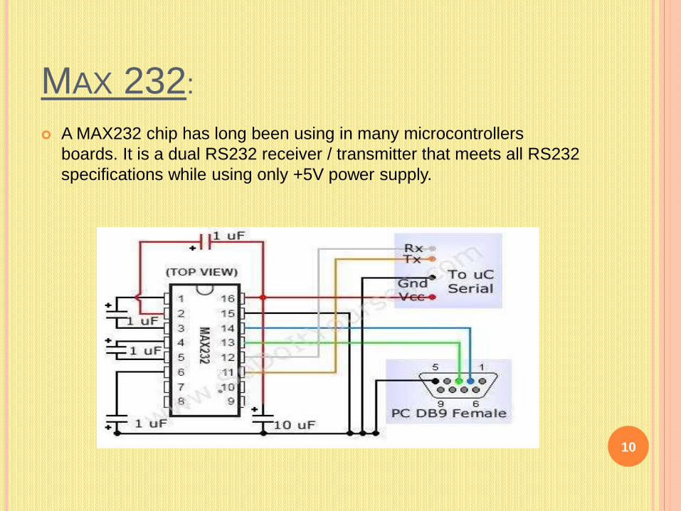
MAX 232:
A MAX232 chip has long been using in many microcontrollers
boards. It is a dual RS232 receiver / transmitter that meets all RS232
specifications while using only +5V power supply.
10

TOUCH SENSOR:
Touch Sensor Technologies designs and manufactures patented
digital switches for use in touch-sensitive User Interface Panels.
Much more durable than mechanical and membrane switches, Touch
Sensor keypads have become the new standard for solid-state
switching.
11

LCD:
A liquid crystal display (LCD) is a thin, flat display device made up of
any number of color or monochrome pixels arrayed in front of a light
source or reflector.
12
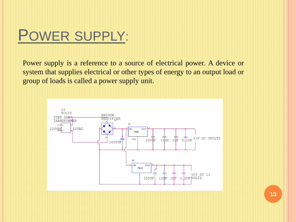
POWER SUPPLY:
13
Power supply is a reference to a source of electrical power. A device or
system that supplies electrical or other types of energy to an output load or
group of loads is called a power supply unit.

CAPACITORS:
A capacitor or condenser is a passive electronic component
consisting of a pair of conductors separated by a dielectric.
14

RESISTORS:
A resistor is a two-terminal electronic component that produces a
voltage across its terminals that is proportional to the electric current
through it in accordance with Ohm's law: V = IR
15
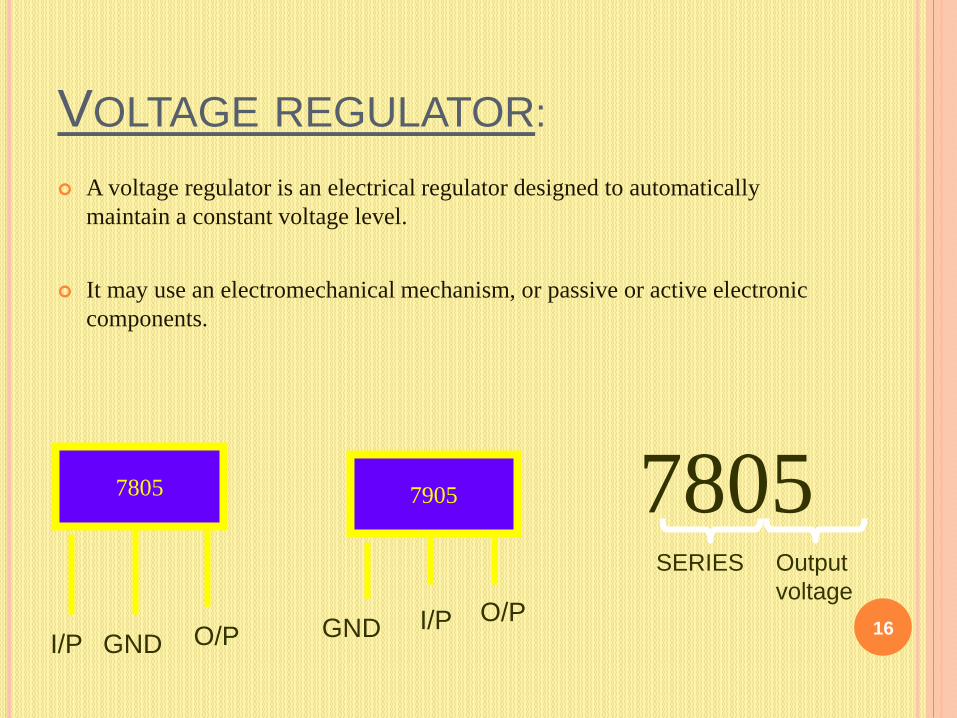
VOLTAGE REGULATOR:
A voltage regulator is an electrical regulator designed to automatically
maintain a constant voltage level.
It may use an electromechanical mechanism, or passive or active electronic
components.
16
7805
I/P GND O/P
7805SERIES Output
voltage
7905
I/P O/PGND

BUZZER:
A buzzer or beeper is a signaling device, usually electronic, typically
used in automobiles.
17

WORKING PRINCIPLE:CIRCUIT DIAGRAM:
18
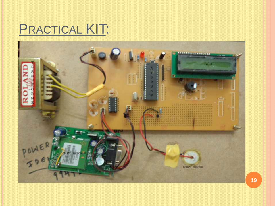
PRACTICAL KIT:
19

APPLICATIONS:
The system can be incorporated for almost all types of users.
The concept is well suited especially for villages and interior
areas.
We by this design like to conclude that the power theft can be
effectively curbed by detecting where the power theft occurs
inform the authorities.
20

ADVANTAGES:
The proposed system provides the solution for some of the main
problems faced by the existing Indian grid system, such as wastage of
energy, power theft, manual billing system, and transmission line fault.
This method will reduce the energy wastage and save a lot of energy
for future use.
We can detect the location from where the power is being stolen which
was not possible before.
Optimized use of energy.
Automatic user identification.
21

LIMITATIONS:
Wide range of frequencies is required to facilitate large
number of users. To overcome this, carrier levels can be
changed from region to region.
Presently, it requires a power supply (230 V) for the operation,
but a small battery with automatic charging facility can be
provided in real time.
Cannot determine who is stealing, but even no other existing
system is capable of doing this.
If implemented on a large scale it may take lot of time and
manual input.22

CONCLUSION:
The project of ours is aimed at reducing the heavy power and
revenue loss that occur due to power theft by the consumers.
The proposed system will be hidden in such meters and as soon as
an attempt is made for the theft, it will send a sms using GSM
modem, by displaying the respective consumer meter number to
control unit of electricity board
Thus by the above mentioned design we can successfully and
effectively address the problems related to power theft.
23

THANK YOU
24