powerbook g4 aluminum 17†repair manual
TRANSCRIPT

Powerbook G4 Aluminum 17” Repair ManualCopyright © 2007 Powerbookmedic.com. All rights reserved.
Any portion of this manual may not be copied, reproduced, or distributed without theexpress written consent of Powerbookmedic.com. Violators will be prosecuted.
This manual is presented as a guide in order to help you repair problems on yourpowerbook. Working on a powerbook can be dangerous if not done properly. We at
Powerbookmedic.com take no responsibility for any damage or harm done to yourself oryour powerbook as a result of reading this guide.
Suggestions for making this manual better? Email: [email protected]
Tools Needed for Take Apart:
Torx T8 Screwdriver – Available from our online store Torx T6 Screwdriver – Available from our online sore
Philips head screwdriver- Available from our online storePutty Knife ( For opening LCD Only)
Always remove the battery and power supply from the computer before beginning anytake apart or repair!

THIS MANUAL ISCURRENTLY IN
PRODUCTION AND ISINCOMPLETE.
The complete version of this manual will be available in 2-3 weeks.
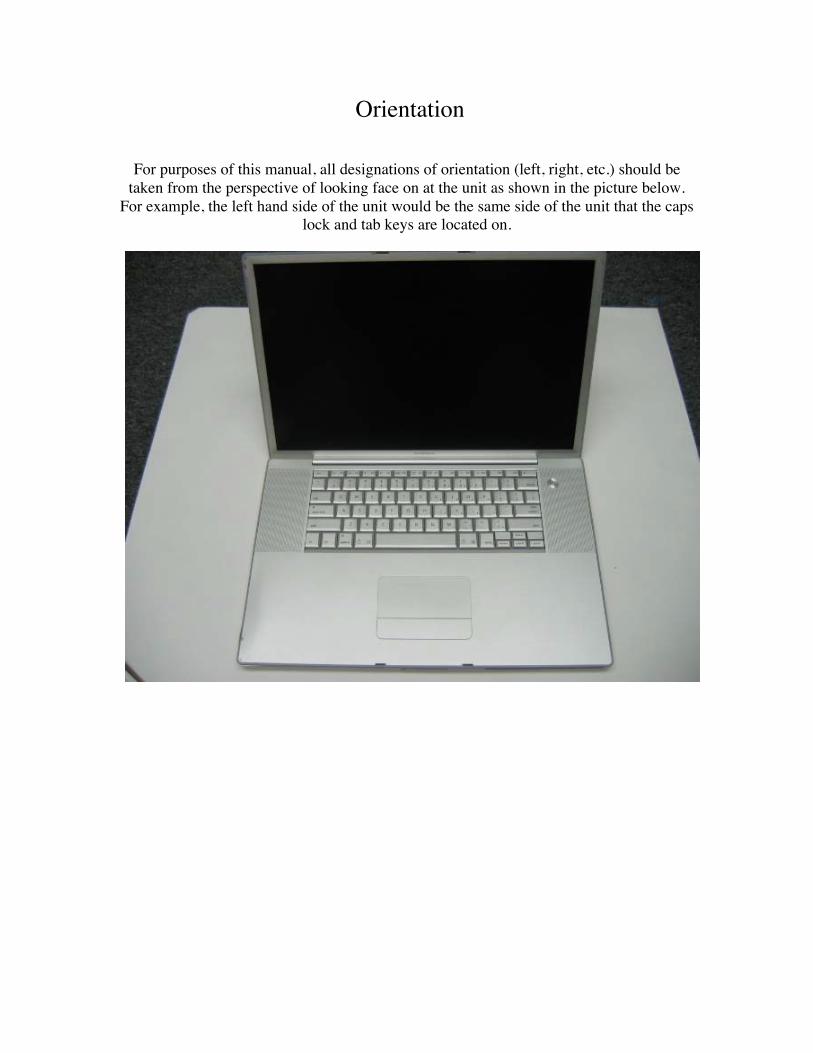
Orientation
For purposes of this manual, all designations of orientation (left, right, etc.) should betaken from the perspective of looking face on at the unit as shown in the picture below.
For example, the left hand side of the unit would be the same side of the unit that the capslock and tab keys are located on.
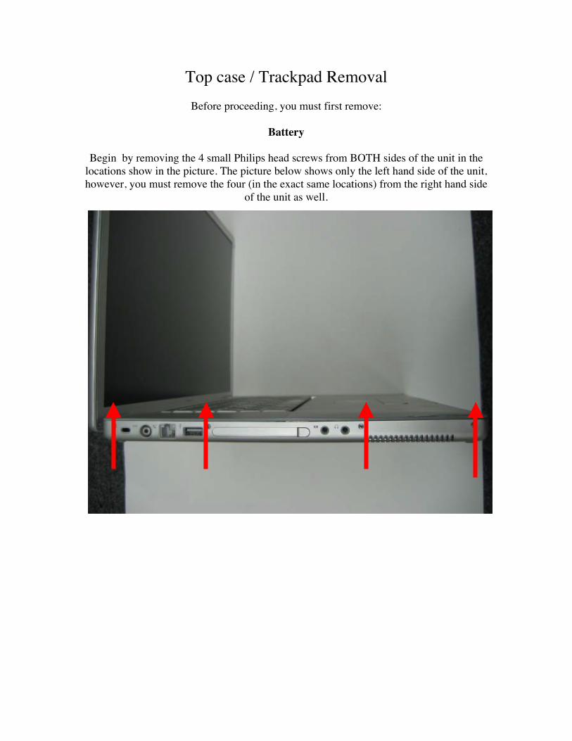
Top case / Trackpad RemovalBefore proceeding, you must first remove:
Battery
Begin by removing the 4 small Philips head screws from BOTH sides of the unit in thelocations show in the picture. The picture below shows only the left hand side of the unit,however, you must remove the four (in the exact same locations) from the right hand side
of the unit as well.
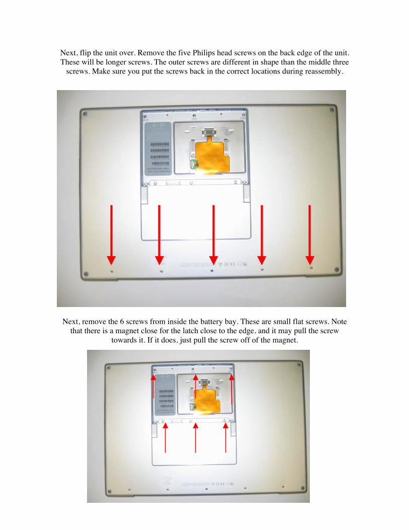
Next, flip the unit over. Remove the five Philips head screws on the back edge of the unit.These will be longer screws. The outer screws are different in shape than the middle three
screws. Make sure you put the screws back in the correct locations during reassembly.
Next, remove the 6 screws from inside the battery bay. These are small flat screws. Notethat there is a magnet close for the latch close to the edge, and it may pull the screw
towards it. If it does, just pull the screw off of the magnet.
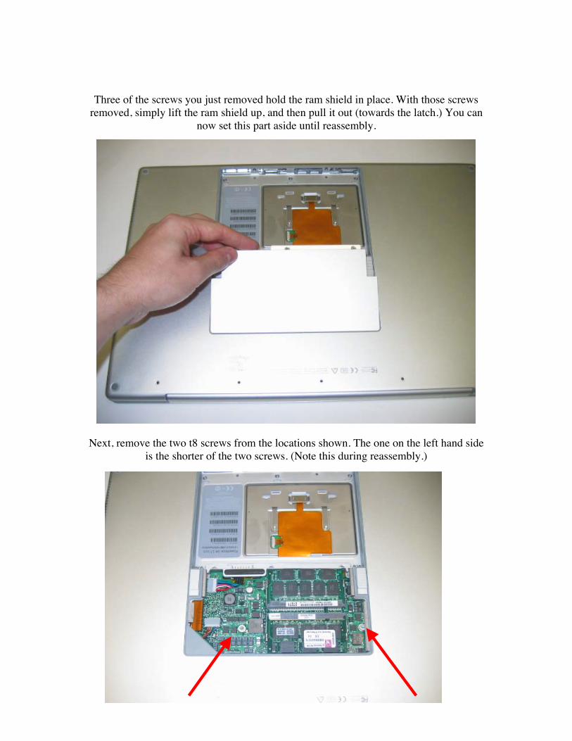
Three of the screws you just removed hold the ram shield in place. With those screwsremoved, simply lift the ram shield up, and then pull it out (towards the latch.) You can
now set this part aside until reassembly.
Next, remove the two t8 screws from the locations shown. The one on the left hand sideis the shorter of the two screws. (Note this during reassembly.)
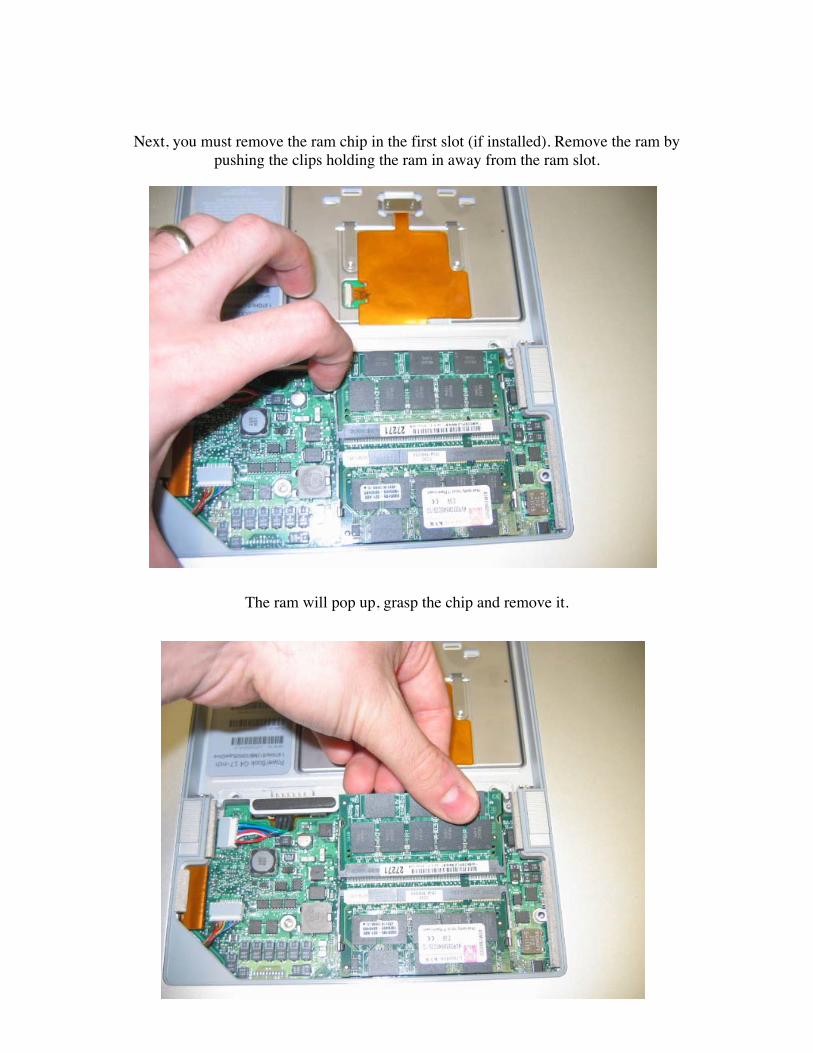
Next, you must remove the ram chip in the first slot (if installed). Remove the ram bypushing the clips holding the ram in away from the ram slot.
The ram will pop up, grasp the chip and remove it.
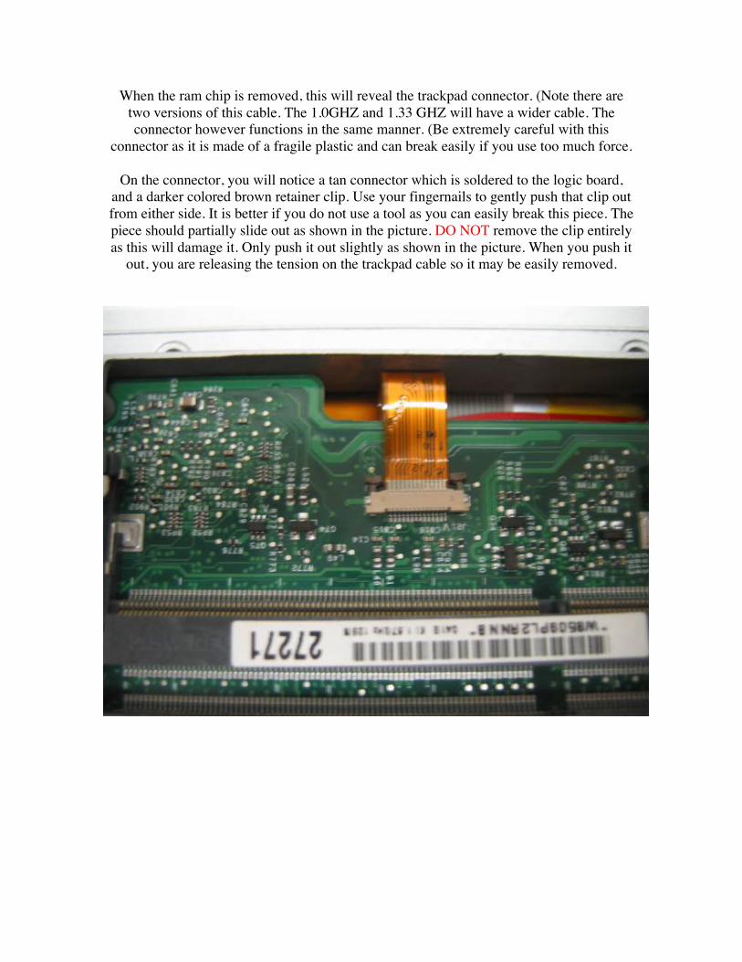
When the ram chip is removed, this will reveal the trackpad connector. (Note there aretwo versions of this cable. The 1.0GHZ and 1.33 GHZ will have a wider cable. Theconnector however functions in the same manner. (Be extremely careful with this
connector as it is made of a fragile plastic and can break easily if you use too much force.
On the connector, you will notice a tan connector which is soldered to the logic board,and a darker colored brown retainer clip. Use your fingernails to gently push that clip outfrom either side. It is better if you do not use a tool as you can easily break this piece. Thepiece should partially slide out as shown in the picture. DO NOT remove the clip entirelyas this will damage it. Only push it out slightly as shown in the picture. When you push it
out, you are releasing the tension on the trackpad cable so it may be easily removed.
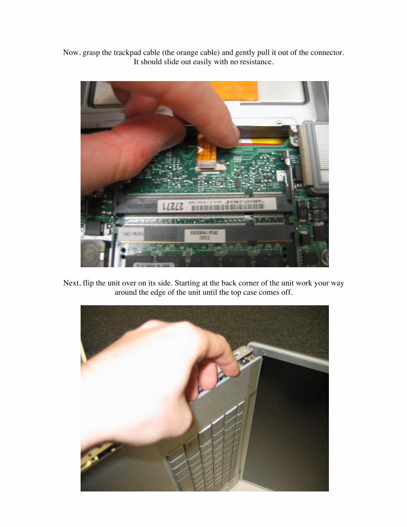
Now, grasp the trackpad cable (the orange cable) and gently pull it out of the connector.It should slide out easily with no resistance.
Next, flip the unit over on its side. Starting at the back corner of the unit work your wayaround the edge of the unit until the top case comes off.
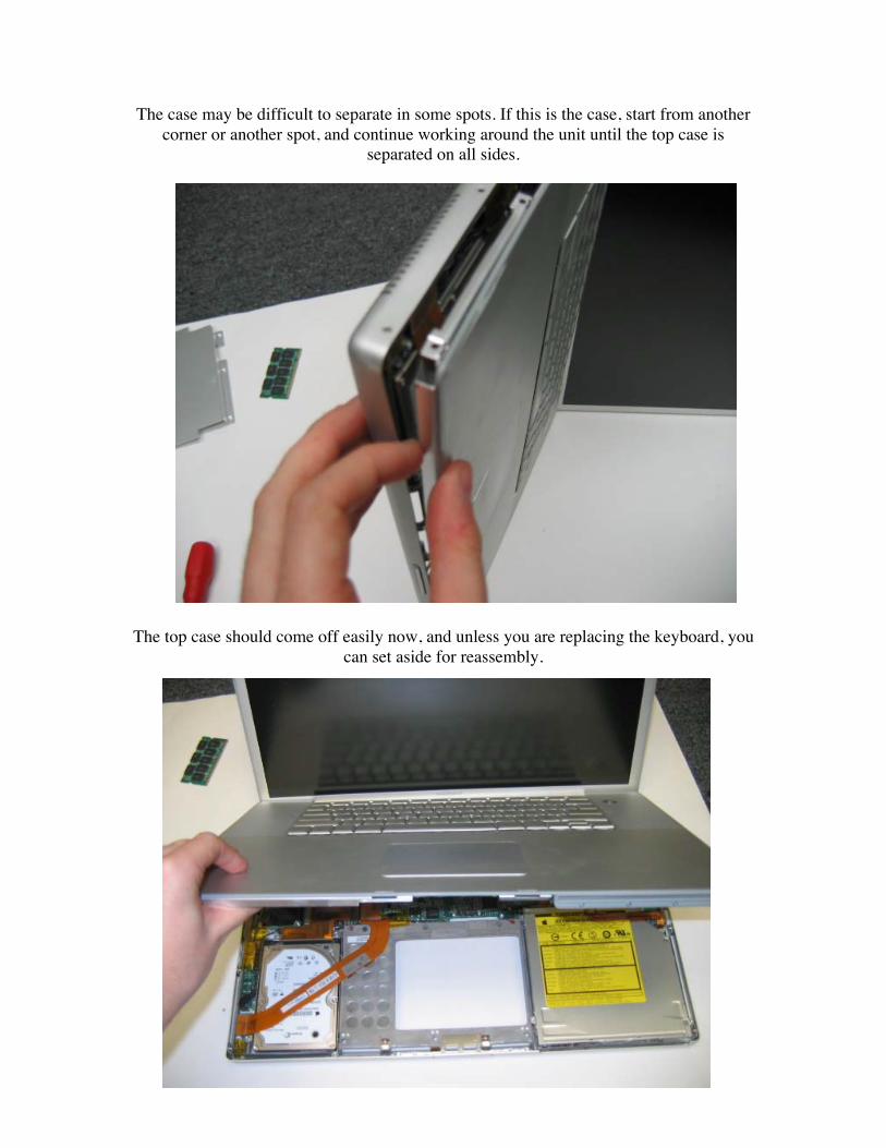
The case may be difficult to separate in some spots. If this is the case, start from anothercorner or another spot, and continue working around the unit until the top case is
separated on all sides.
The top case should come off easily now, and unless you are replacing the keyboard, youcan set aside for reassembly.
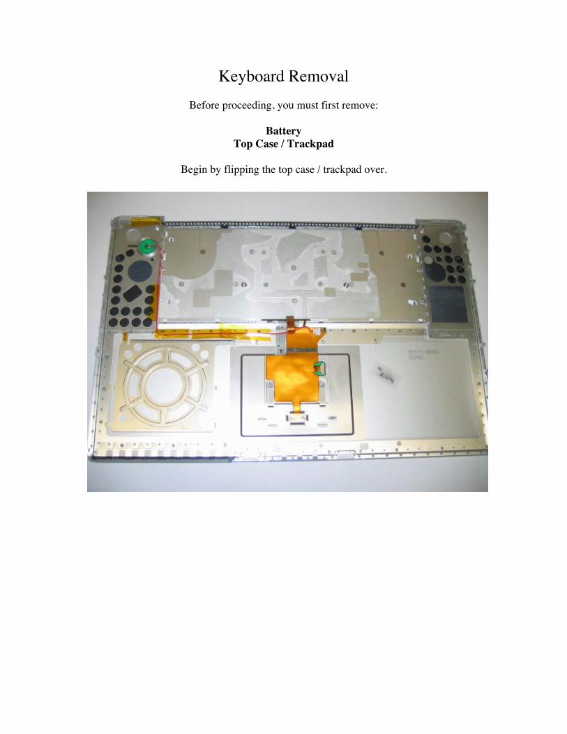
Keyboard RemovalBefore proceeding, you must first remove:
BatteryTop Case / Trackpad
Begin by flipping the top case / trackpad over.
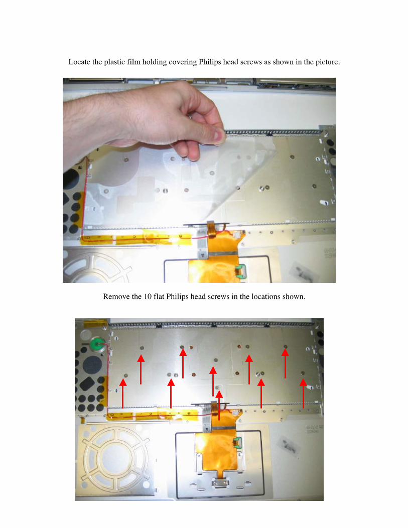
Locate the plastic film holding covering Philips head screws as shown in the picture.
Remove the 10 flat Philips head screws in the locations shown.
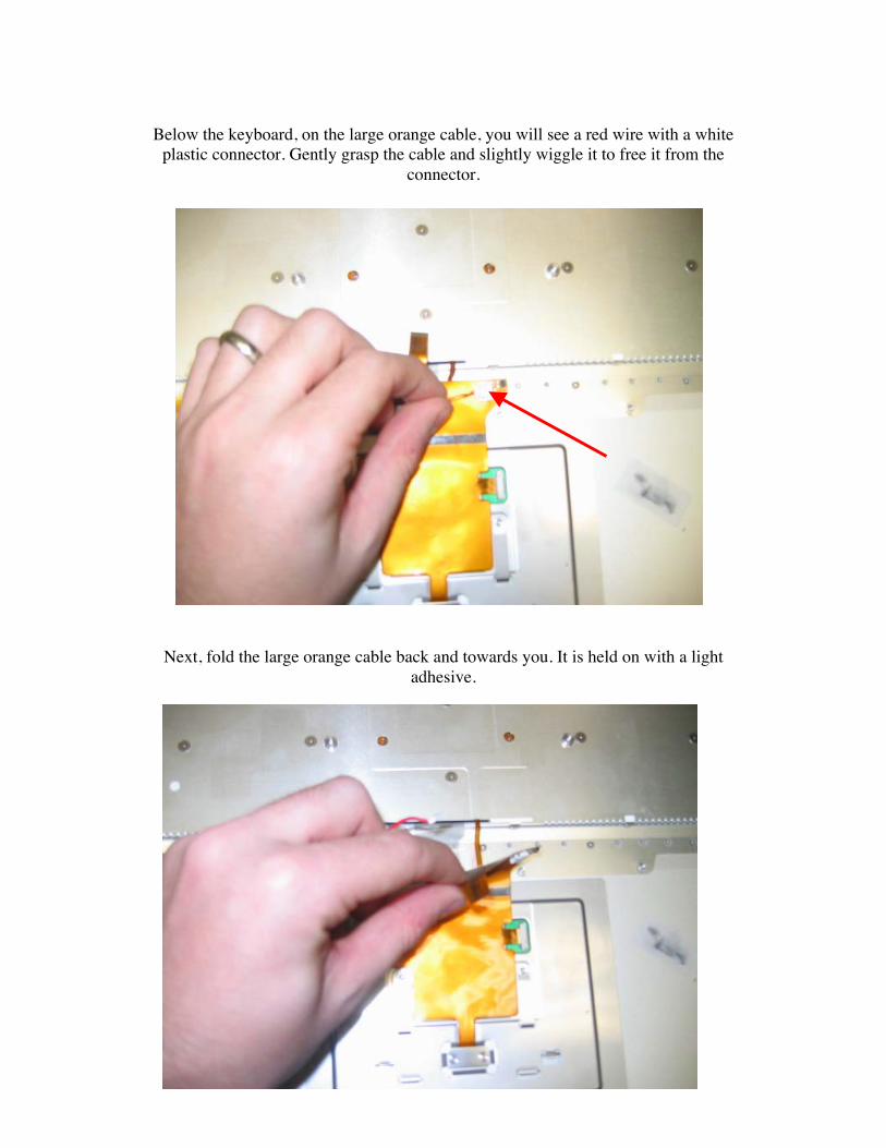
Below the keyboard, on the large orange cable, you will see a red wire with a whiteplastic connector. Gently grasp the cable and slightly wiggle it to free it from the
connector.
Next, fold the large orange cable back and towards you. It is held on with a lightadhesive.
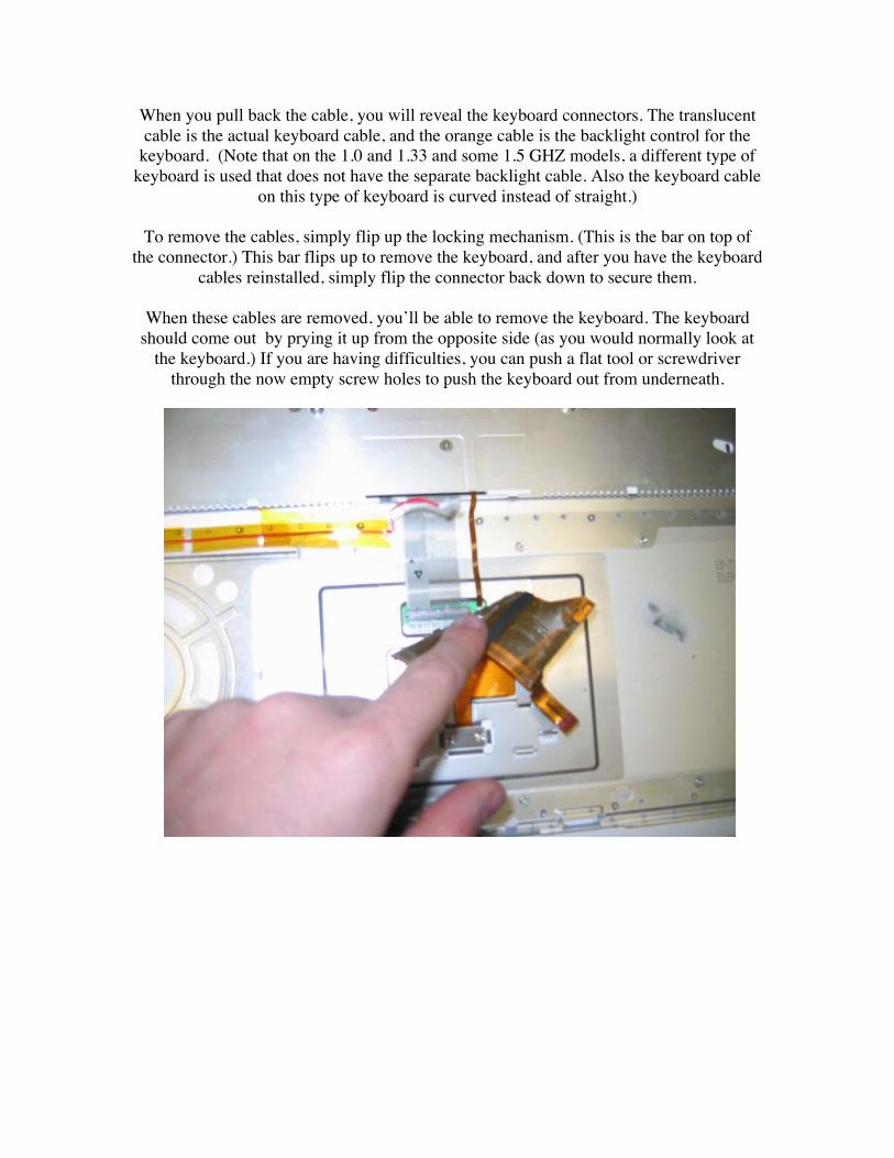
When you pull back the cable, you will reveal the keyboard connectors. The translucentcable is the actual keyboard cable, and the orange cable is the backlight control for the
keyboard. (Note that on the 1.0 and 1.33 and some 1.5 GHZ models, a different type ofkeyboard is used that does not have the separate backlight cable. Also the keyboard cable
on this type of keyboard is curved instead of straight.)
To remove the cables, simply flip up the locking mechanism. (This is the bar on top ofthe connector.) This bar flips up to remove the keyboard, and after you have the keyboard
cables reinstalled, simply flip the connector back down to secure them.
When these cables are removed, you’ll be able to remove the keyboard. The keyboardshould come out by prying it up from the opposite side (as you would normally look at
the keyboard.) If you are having difficulties, you can push a flat tool or screwdriverthrough the now empty screw holes to push the keyboard out from underneath.
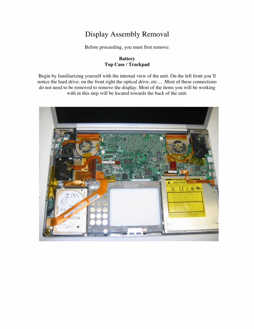
Display Assembly RemovalBefore proceeding, you must first remove:
BatteryTop Case / Trackpad
Begin by familiarizing yourself with the internal view of the unit. On the left front you’llnotice the hard drive, on the front right the optical drive, etc… Most of these connectionsdo not need to be removed to remove the display. Most of the items you will be working
with in this step will be located towards the back of the unit.
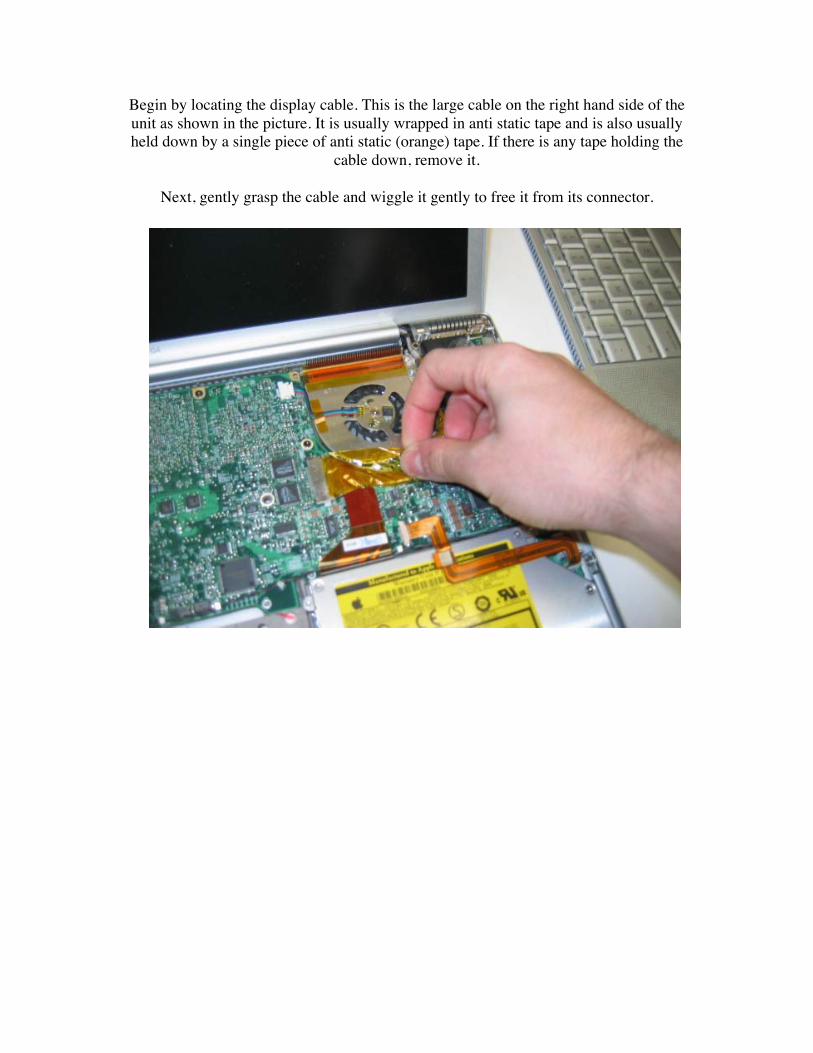
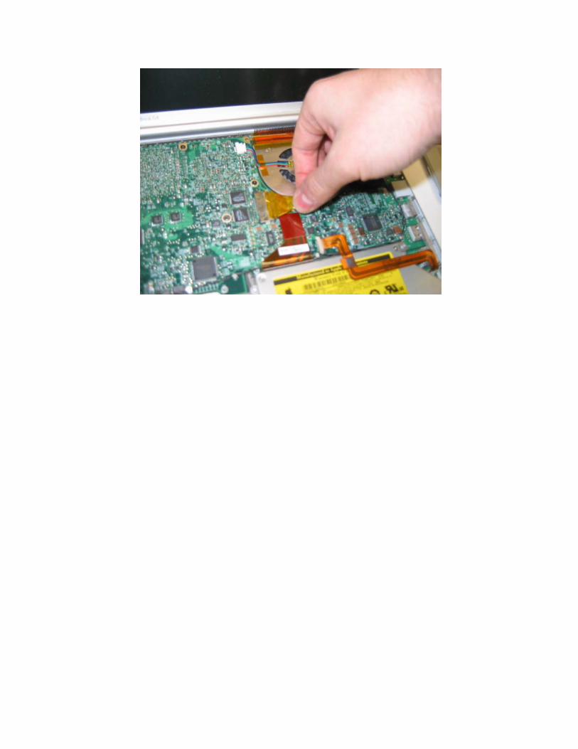
Begin by locating the display cable. This is the large cable on the right hand side of theunit as shown in the picture. It is usually wrapped in anti static tape and is also usuallyheld down by a single piece of anti static (orange) tape. If there is any tape holding the
cable down, remove it.
Next, gently grasp the cable and wiggle it gently to free it from its connector.
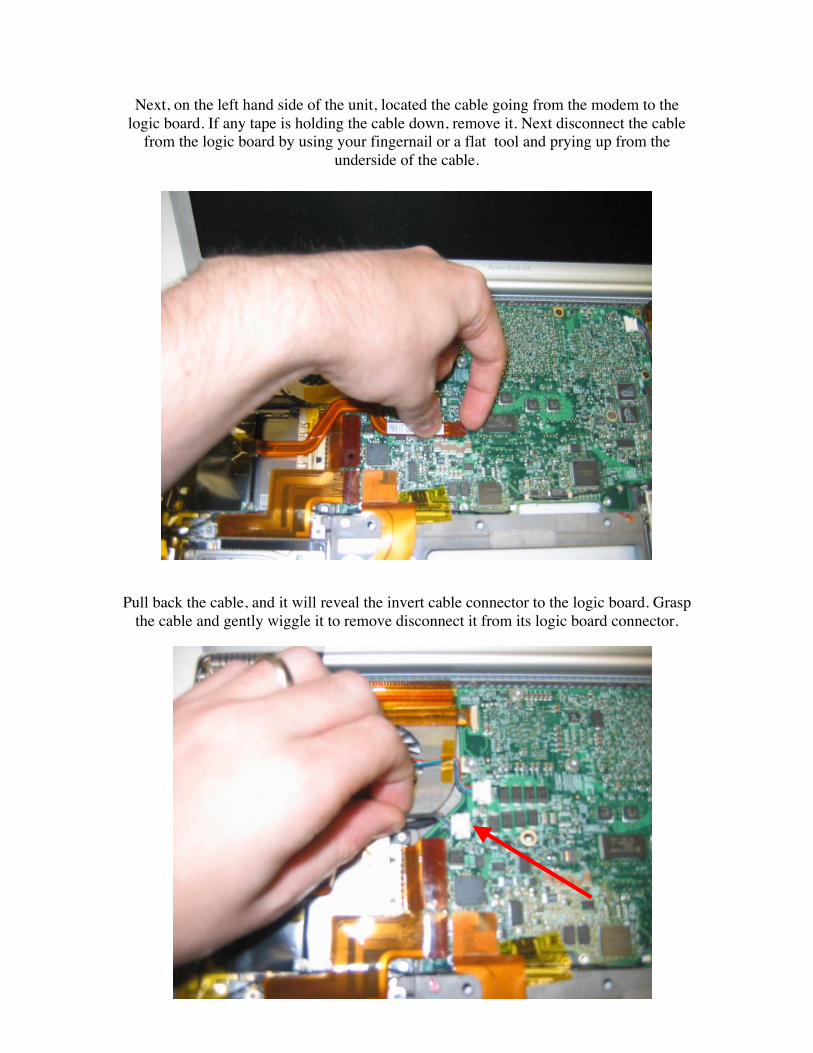
Next, on the left hand side of the unit, located the cable going from the modem to thelogic board. If any tape is holding the cable down, remove it. Next disconnect the cable
from the logic board by using your fingernail or a flat tool and prying up from theunderside of the cable.
Pull back the cable, and it will reveal the invert cable connector to the logic board. Graspthe cable and gently wiggle it to remove disconnect it from its logic board connector.

Next, disconnect the orange dc-in cable. This connector is the same style connector at thetrackpad ribbon cable connector. Use the same method and precautions for removing this
cable.
When the DC-IN cable is free, you will have access to the airport cable connection.Locate a black cable held with a gold metal piece in the middle.
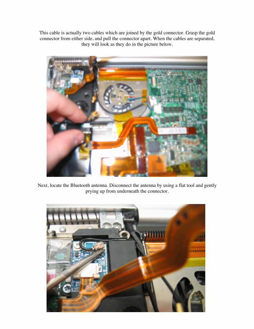
This cable is actually two cables which are joined by the gold connector. Grasp the goldconnector from either side, and pull the connector apart. When the cables are separated,
they will look as they do in the picture below.
Next, locate the Bluetooth antenna. Disconnect the antenna by using a flat tool and gentlyprying up from underneath the connector.

On the left hand back of the unit, lift up the bundle of cables coming out of the hinge asshown, and this will reveal a black plastic holder held in place by a single T6 screw.
Remove this screw.
Next, remove the 4 T6 screws from the locations shown. You DO NOT need to removethe two t6 screws in the middle, just the two on each side. Also note that when you
remove the two screws on the left hand side you may here a pop and the piece may moveas this is a tension component. It is completely normal for this to happen on both sides.
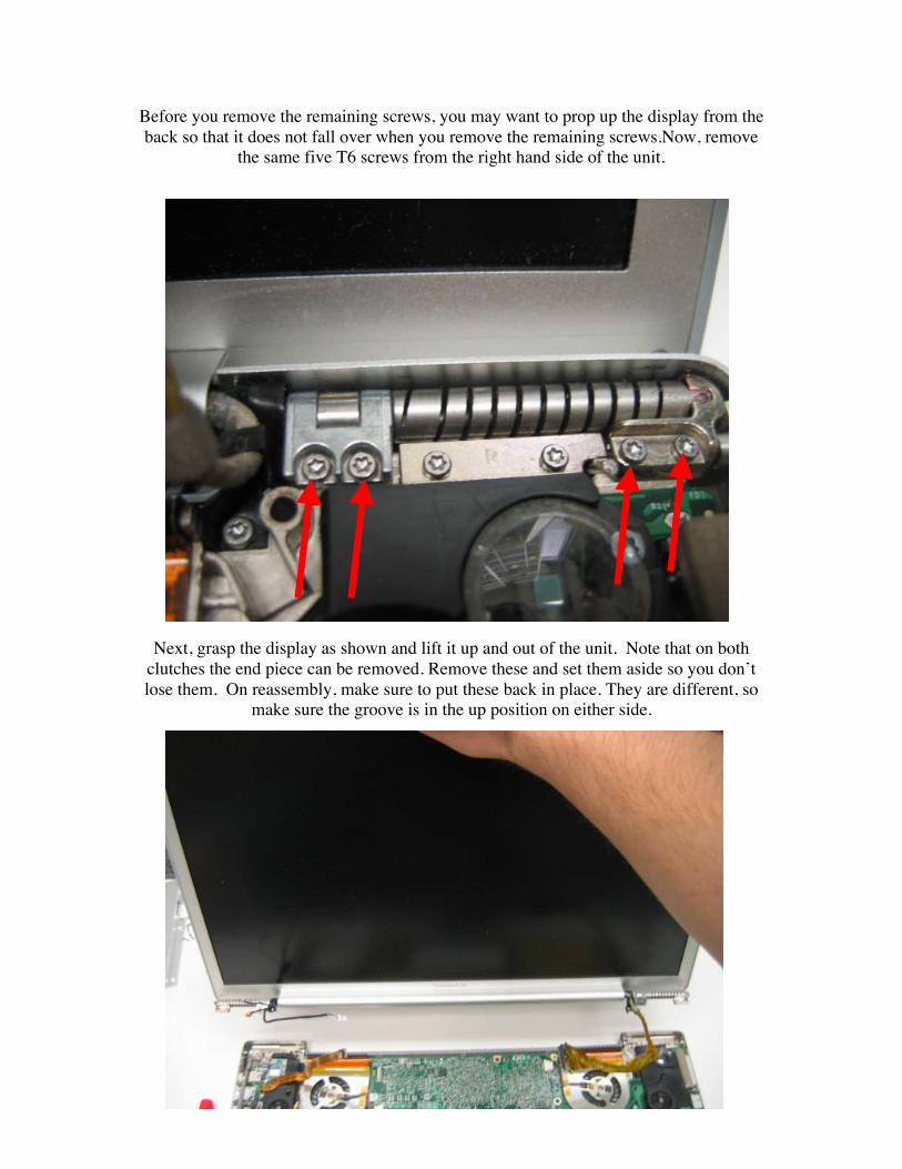
Before you remove the remaining screws, you may want to prop up the display from theback so that it does not fall over when you remove the remaining screws.Now, remove
the same five T6 screws from the right hand side of the unit.
Next, grasp the display as shown and lift it up and out of the unit. Note that on bothclutches the end piece can be removed. Remove these and set them aside so you don’tlose them. On reassembly, make sure to put these back in place. They are different, so
make sure the groove is in the up position on either side.
Display Back Panel RemovalBefore proceeding, you must first remove:
BatteryTop Case / Trackpad
Display Assembly
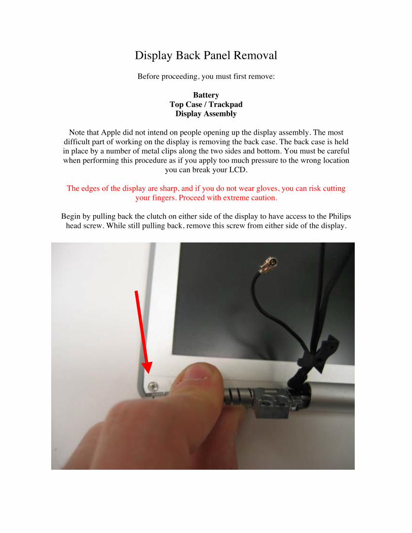
Note that Apple did not intend on people opening up the display assembly. The mostdifficult part of working on the display is removing the back case. The back case is heldin place by a number of metal clips along the two sides and bottom. You must be carefulwhen performing this procedure as if you apply too much pressure to the wrong location
you can break your LCD.
The edges of the display are sharp, and if you do not wear gloves, you can risk cuttingyour fingers. Proceed with extreme caution.
Begin by pulling back the clutch on either side of the display to have access to the Philipshead screw. While still pulling back, remove this screw from either side of the display.
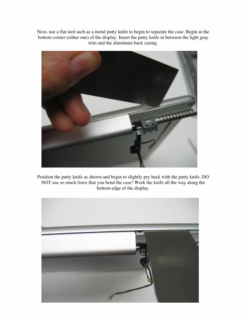
Next, use a flat tool such as a metal putty knife to begin to separate the case. Begin at thebottom corner (either one) of the display. Insert the putty knife in between the light gray
trim and the aluminum back casing.
Position the putty knife as shown and begin to slightly pry back with the putty knife. DONOT use so much force that you bend the case! Work the knife all the way along the
bottom edge of the display.
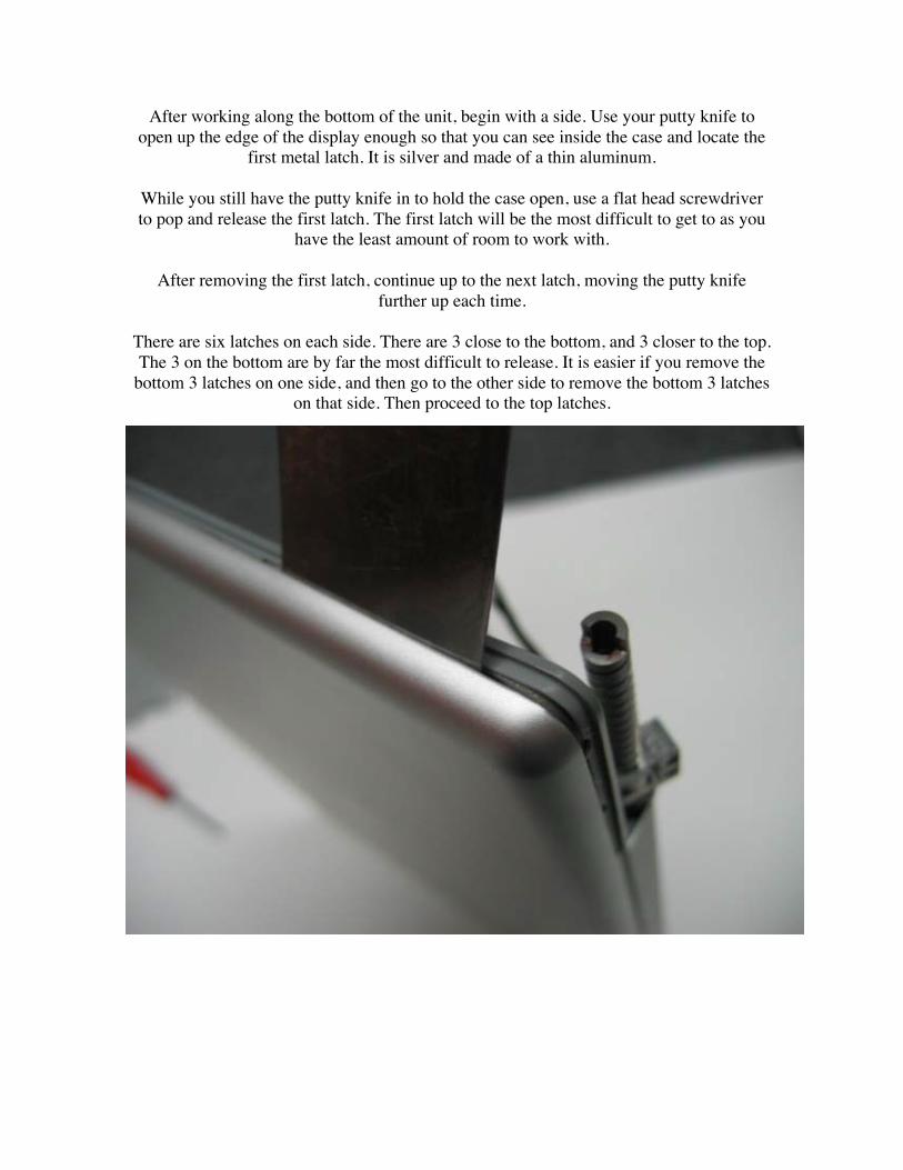
After working along the bottom of the unit, begin with a side. Use your putty knife toopen up the edge of the display enough so that you can see inside the case and locate the
first metal latch. It is silver and made of a thin aluminum.
While you still have the putty knife in to hold the case open, use a flat head screwdriverto pop and release the first latch. The first latch will be the most difficult to get to as you
have the least amount of room to work with.
After removing the first latch, continue up to the next latch, moving the putty knifefurther up each time.
There are six latches on each side. There are 3 close to the bottom, and 3 closer to the top.The 3 on the bottom are by far the most difficult to release. It is easier if you remove the
bottom 3 latches on one side, and then go to the other side to remove the bottom 3 latcheson that side. Then proceed to the top latches.
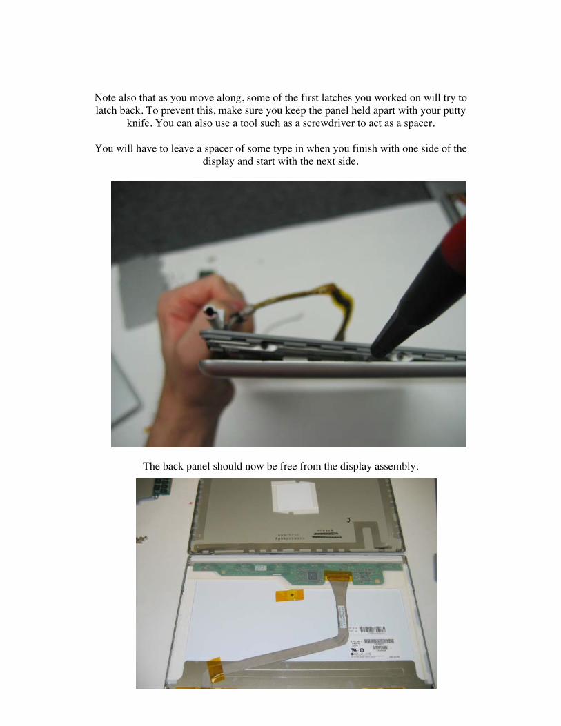
Note also that as you move along, some of the first latches you worked on will try tolatch back. To prevent this, make sure you keep the panel held apart with your putty
knife. You can also use a tool such as a screwdriver to act as a spacer.
You will have to leave a spacer of some type in when you finish with one side of thedisplay and start with the next side.
The back panel should now be free from the display assembly.
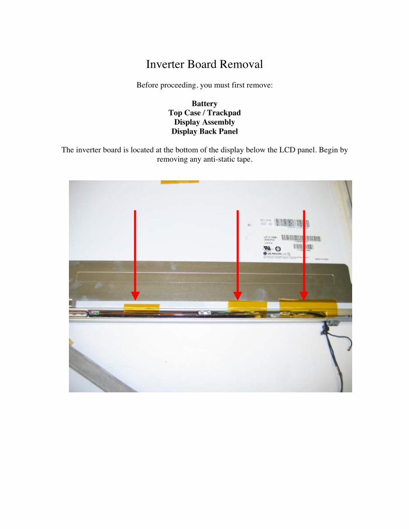
Inverter Board RemovalBefore proceeding, you must first remove:
BatteryTop Case / Trackpad
Display AssemblyDisplay Back Panel
The inverter board is located at the bottom of the display below the LCD panel. Begin byremoving any anti-static tape.
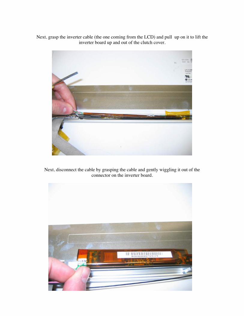
Next, grasp the inverter cable (the one coming from the LCD) and pull up on it to lift theinverter board up and out of the clutch cover.
Next, disconnect the cable by grasping the cable and gently wiggling it out of theconnector on the inverter board.
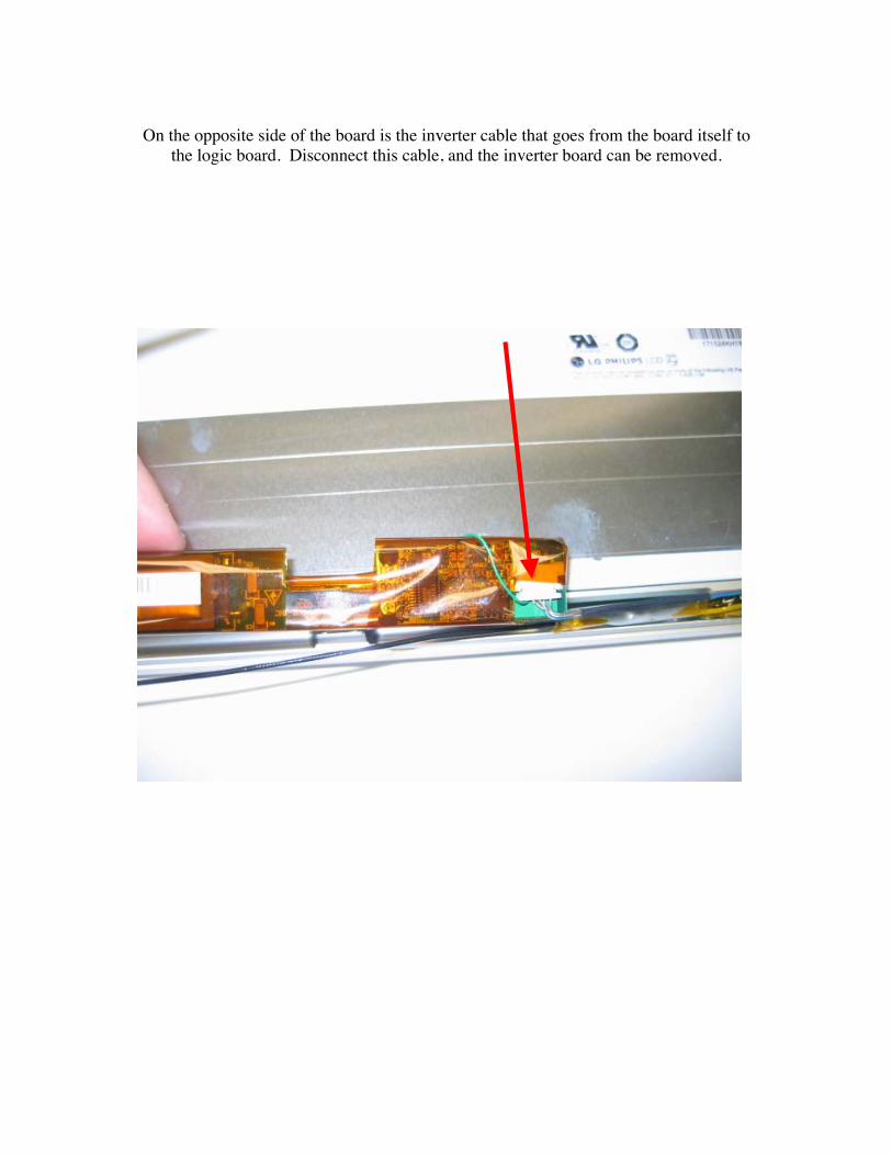
On the opposite side of the board is the inverter cable that goes from the board itself tothe logic board. Disconnect this cable, and the inverter board can be removed.
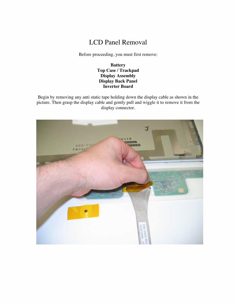
LCD Panel RemovalBefore proceeding, you must first remove:
BatteryTop Case / Trackpad
Display AssemblyDisplay Back Panel
Inverter Board
Begin by removing any anti static tape holding down the display cable as shown in thepicture. Then grasp the display cable and gently pull and wiggle it to remove it from the
display connector.
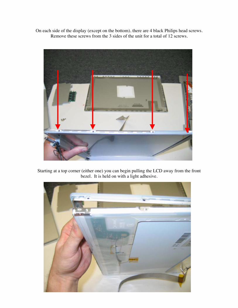
On each side of the display (except on the bottom), there are 4 black Philips head screws.Remove these screws from the 3 sides of the unit for a total of 12 screws.
Starting at a top corner (either one) you can begin pulling the LCD away from the frontbezel. It is held on with a light adhesive.
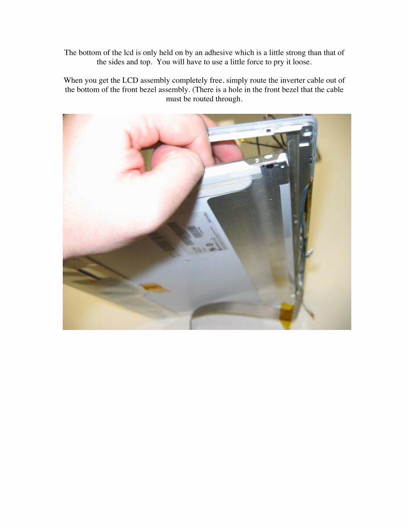
The bottom of the lcd is only held on by an adhesive which is a little strong than that ofthe sides and top. You will have to use a little force to pry it loose.
When you get the LCD assembly completely free, simply route the inverter cable out ofthe bottom of the front bezel assembly. (There is a hole in the front bezel that the cable
must be routed through.