service source powerbook g4 (12-inch 1.5 ghz)
TRANSCRIPT
© 2005, 2007 Apple Inc. All rights reserved.
Service Source
PowerBook G4 (12-inch 1.5 GHz)
Updated August 1, 2007
© 2005 Apple Computer, Inc. All rights reserved.
Service Source
Take Apart
PowerBook G4 (12-inch 1.5 GHz)
PowerBook G4 (12-inch 1.5 GHz) Take Apart -
1
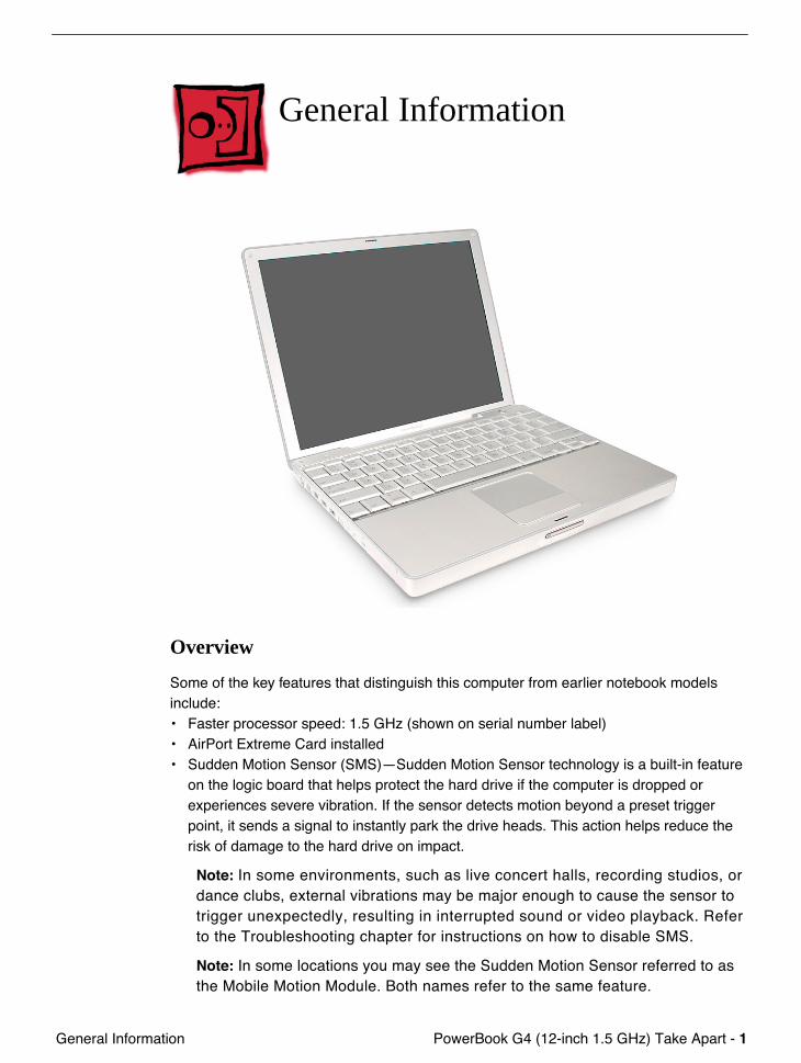
General Information
General Information
Overview
Some of the key features that distinguish this computer from earlier notebook models include: • Faster processor speed: 1.5 GHz (shown on serial number label)• AirPort Extreme Card installed• Sudden Motion Sensor (SMS)—Sudden Motion Sensor technology is a built-in feature
on the logic board that helps protect the hard drive if the computer is dropped or experiences severe vibration. If the sensor detects motion beyond a preset trigger point, it sends a signal to instantly park the drive heads. This action helps reduce the risk of damage to the hard drive on impact.
Note:
In some environments, such as live concert halls, recording studios, or dance clubs, external vibrations may be major enough to cause the sensor to trigger unexpectedly, resulting in interrupted sound or video playback. Refer to the Troubleshooting chapter for instructions on how to disable SMS.
Note:
In some locations you may see the Sudden Motion Sensor referred to as the Mobile Motion Module. Both names refer to the same feature.
2 -
PowerBook G4 (12-inch 1.5 GHz) Take Apart General Information
• Scrolling Trackpad—A new trackpad feature allows faster navigation in windows with scroll bars. To scroll or pan vertically, move two adjoining fingers up or down the trackpad. To scroll or pan horizontally, move two adjoining fingers left or right on the trackpad. You can customize this feature or turn it off in the Keyboard & Mouse pane of System Preferences.
Note:
If you find that the pointer moves as you type because you accidentally brush the trackpad, make sure that the "Ignore accidental trackpad input" option in the Keyboard & Mouse pane of System Preferences is selected. For more information on using the trackpad, choose Help > Mac Help from the menu bar at the top of the screen.
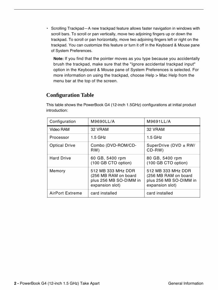
Configuration Table
This table shows the PowerBook G4 (12-inch 1.5GHz) configurations at initial product introduction:
Configuration M9690LL/A M9691LL/A
Video RAM 32 VRAM 32 VRAM
Processor 1.5 GHz 1.5 GHz
Optical Drive Combo (DVD-ROM/CD-RW)
SuperDrive (DVD ± RW/CD-RW)
Hard Drive 60 GB, 5400 rpm(100 GB CTO option)
80 GB, 5400 rpm(100 GB CTO option)
Memory 512 MB 333 MHz DDR (256 MB RAM on board plus 256 MB SO-DIMM in expansion slot)
512 MB 333 MHz DDR (256 MB RAM on board plus 256 MB SO-DIMM in expansion slot)
AirPort Extreme card installed card installed
PowerBook G4 (12-inch 1.5 GHz) Take Apart -
3
General Information
Model Differences
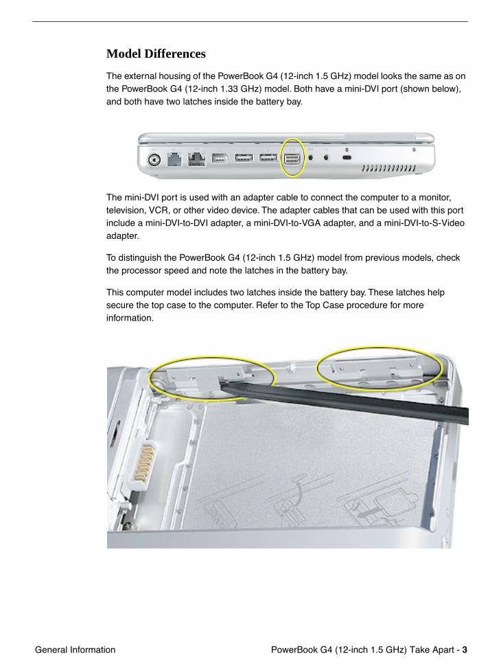
The external housing of the PowerBook G4 (12-inch 1.5 GHz) model looks the same as on the PowerBook G4 (12-inch 1.33 GHz) model. Both have a mini-DVI port (shown below), and both have two latches inside the battery bay.
The mini-DVI port is used with an adapter cable to connect the computer to a monitor, television, VCR, or other video device. The adapter cables that can be used with this port include a mini-DVI-to-DVI adapter, a mini-DVI-to-VGA adapter, and a mini-DVI-to-S-Video adapter.
To distinguish the PowerBook G4 (12-inch 1.5 GHz) model from previous models, check the processor speed and note the latches in the battery bay.
This computer model includes two latches inside the battery bay. These latches help secure the top case to the computer. Refer to the Top Case procedure for more information.
4 -
PowerBook G4 (12-inch 1.5 GHz) Take Apart General Information
Tools
The following tools are recommended for this computer:• Coin• ESD wriststrap and mat• Small soft cloth• Black stick (or other nonconductive nylon or plastic flat-blade tool) • #0 Phillips screwdriver (magnetized)• #1 Phillips screwdriver (magnetized)• Jeweler’s flat-blade screwdriver• 1.5 mm hex driver • 4 mm socket wrench or needlenose pliers• nonconductive tweezers or needlenose pliers (for replacing a foot or for routing thin
cables such as the AirPort antenna cable)
Important:
To organize the screws you remove from the computer, use a tray with divided compartments (such as a plastic ice cube tray). If doing a complete disassembly, note the screws removed from each location in the computer.
Warning:
Check the screw lengths before installing the screws. Installing a longer screw in the wrong place can permanently damage the housing or an internal part.
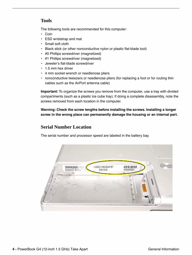
Serial Number Location
The serial number and processor speed are labeled in the battery bay.
PowerBook G4 (12-inch 1.5 GHz) Take Apart -
5
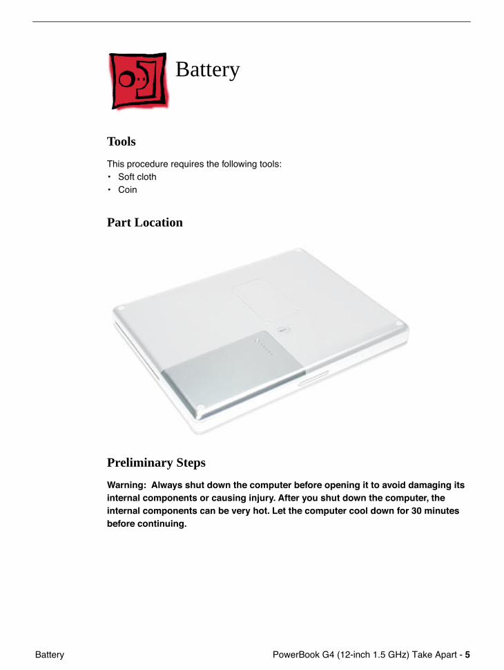
Battery
Battery
Tools
This procedure requires the following tools:• Soft cloth• Coin
Part Location
Preliminary Steps
Warning: Always shut down the computer before opening it to avoid damaging its internal components or causing injury. After you shut down the computer, the internal components can be very hot. Let the computer cool down for 30 minutes before continuing.
6 -
PowerBook G4 (12-inch 1.5 GHz) Take Apart Battery
Procedure
Warning:
If the computer has been recently operating, allow it to cool down before performing this procedure.
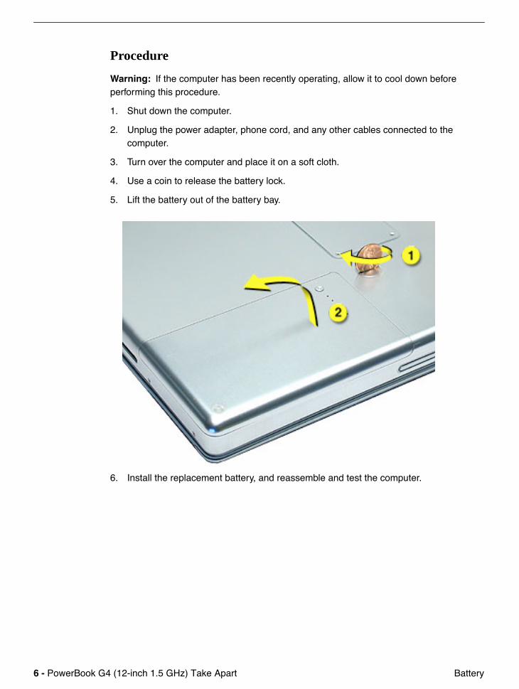
1. Shut down the computer.
2. Unplug the power adapter, phone cord, and any other cables connected to the computer.
3. Turn over the computer and place it on a soft cloth.
4. Use a coin to release the battery lock.
5. Lift the battery out of the battery bay.
6. Install the replacement battery, and reassemble and test the computer.
PowerBook G4 (12-inch 1.5 GHz) Take Apart -
7
Feet
Feet
Tools
This procedure requires the following tools:• Foot kit• Tweezers or needlenose pliers• Soft cloth
Preliminary Step
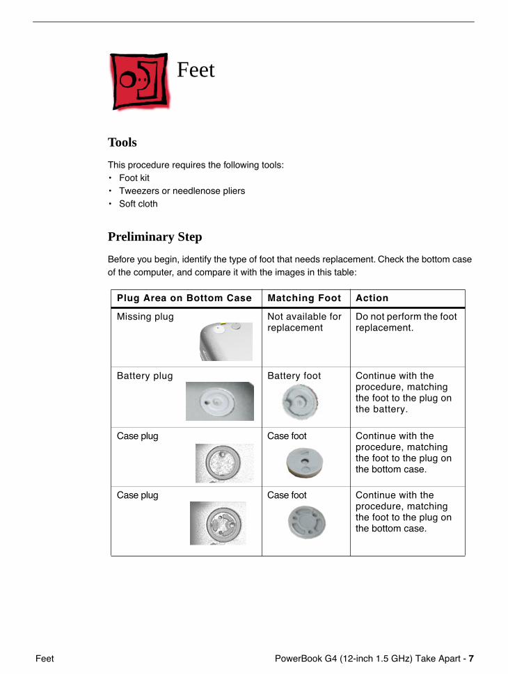
Before you begin, identify the type of foot that needs replacement. Check the bottom case of the computer, and compare it with the images in this table:
Plug Area on Bottom Case Matching Foot Action
Missing plug Not available for replacement
Do not perform the foot replacement.
Battery plug Battery foot Continue with the procedure, matching the foot to the plug on the battery.
Case plug Case foot Continue with the procedure, matching the foot to the plug on the bottom case.
Case plug Case foot Continue with the procedure, matching the foot to the plug on the bottom case.

8 -
PowerBook G4 (12-inch 1.5 GHz) Take Apart Feet
Procedure
Warning:
The glue used in this procedure can bond instantly to skin. Do not touch the glue. In the event of contact, review the safety instructions at the end of this document. For additional information, refer to the glue manufacturer:
Elmer's Products, Inc.Columbus, OH. 43215-3799www.krazyglue.com
1. Place the computer upside down on a clean, lint-free cloth or other nonabrasive surface.
2. Select a foot from the kit that matches the plug on the bottom case. (Refer to the images shown in the table.) Do not use a foot that does not match.
3. Make sure the plug area on the bottom case is clean. If any portion of the soft rubber foot remains, remove it so that only the hard plastic plug is visible (as shown below).
Battery Plug Case Plug
Important:
Notice the inner ring of the plug. When positioning the foot, make sure the textured plane of the rubber foot fits into the compatible ring in the plug. This ensures a balanced and level fitting.
PowerBook G4 (12-inch 1.5 GHz) Take Apart -
9
Feet
4.
Warning:
GLUE IS AN EYE AND SKIN IRRITANT. BONDS SKIN INSTANTLY. Do not touch the glue at any time. Before opening the glue, review the safety instructions at the end of this document.
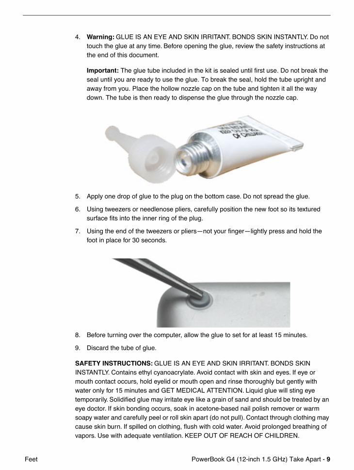
Important:
The glue tube included in the kit is sealed until first use. Do not break the seal until you are ready to use the glue. To break the seal, hold the tube upright and away from you. Place the hollow nozzle cap on the tube and tighten it all the way down. The tube is then ready to dispense the glue through the nozzle cap.
5. Apply one drop of glue to the plug on the bottom case. Do not spread the glue.
6. Using tweezers or needlenose pliers, carefully position the new foot so its textured surface fits into the inner ring of the plug.
7. Using the end of the tweezers or pliers—not your finger—lightly press and hold the foot in place for 30 seconds.
8. Before turning over the computer, allow the glue to set for at least 15 minutes.
9. Discard the tube of glue.
SAFETY INSTRUCTIONS:
GLUE IS AN EYE AND SKIN IRRITANT. BONDS SKIN INSTANTLY. Contains ethyl cyanoacrylate. Avoid contact with skin and eyes. If eye or mouth contact occurs, hold eyelid or mouth open and rinse thoroughly but gently with water only for 15 minutes and GET MEDICAL ATTENTION. Liquid glue will sting eye temporarily. Solidified glue may irritate eye like a grain of sand and should be treated by an eye doctor. If skin bonding occurs, soak in acetone-based nail polish remover or warm soapy water and carefully peel or roll skin apart (do not pull). Contact through clothing may cause skin burn. If spilled on clothing, flush with cold water. Avoid prolonged breathing of vapors. Use with adequate ventilation. KEEP OUT OF REACH OF CHILDREN.
10 -
PowerBook G4 (12-inch 1.5 GHz) Take Apart Memory Door and Memory Card
Memory Door and Memory Card
Tools
This procedure requires the following tools:• Soft cloth• #0 Phillips screwdriver • Black stick (or other nonconductive nylon or plastic flat-blade tool)
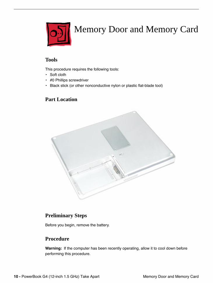
Part Location
Preliminary Steps
Before you begin, remove the battery.
Procedure
Warning:
If the computer has been recently operating, allow it to cool down before performing this procedure.
PowerBook G4 (12-inch 1.5 GHz) Take Apart -
11
Memory Door and Memory Card
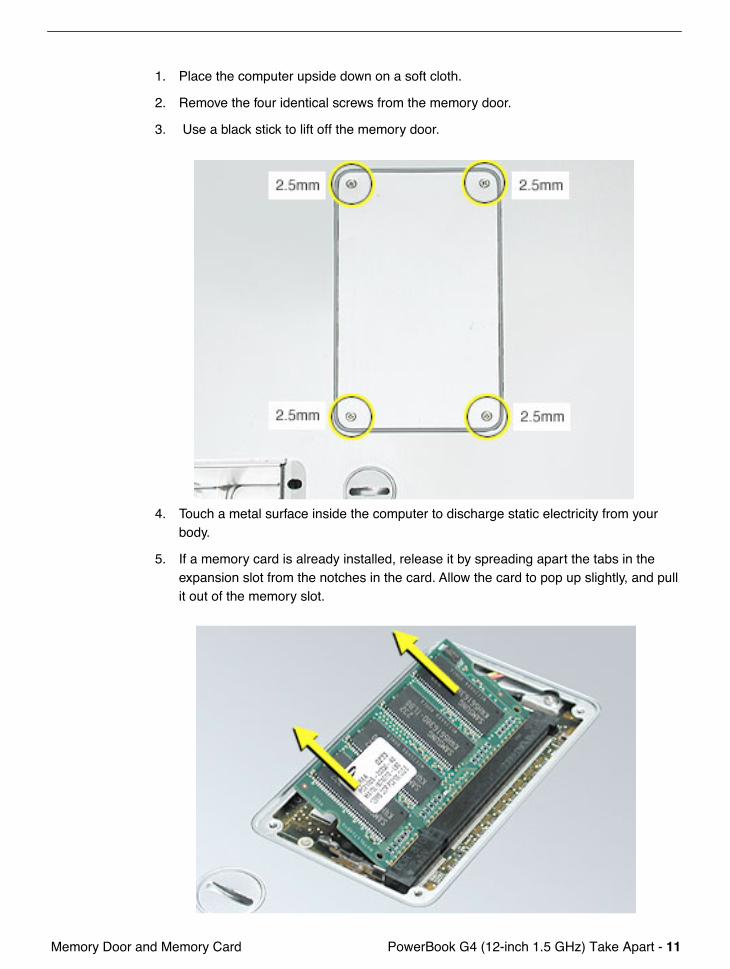
1. Place the computer upside down on a soft cloth.
2. Remove the four identical screws from the memory door.
3. Use a black stick to lift off the memory door.
4. Touch a metal surface inside the computer to discharge static electricity from your body.
5. If a memory card is already installed, release it by spreading apart the tabs in the expansion slot from the notches in the card. Allow the card to pop up slightly, and pull it out of the memory slot.
12 -
PowerBook G4 (12-inch 1.5 GHz) Take Apart Memory Door and Memory Card
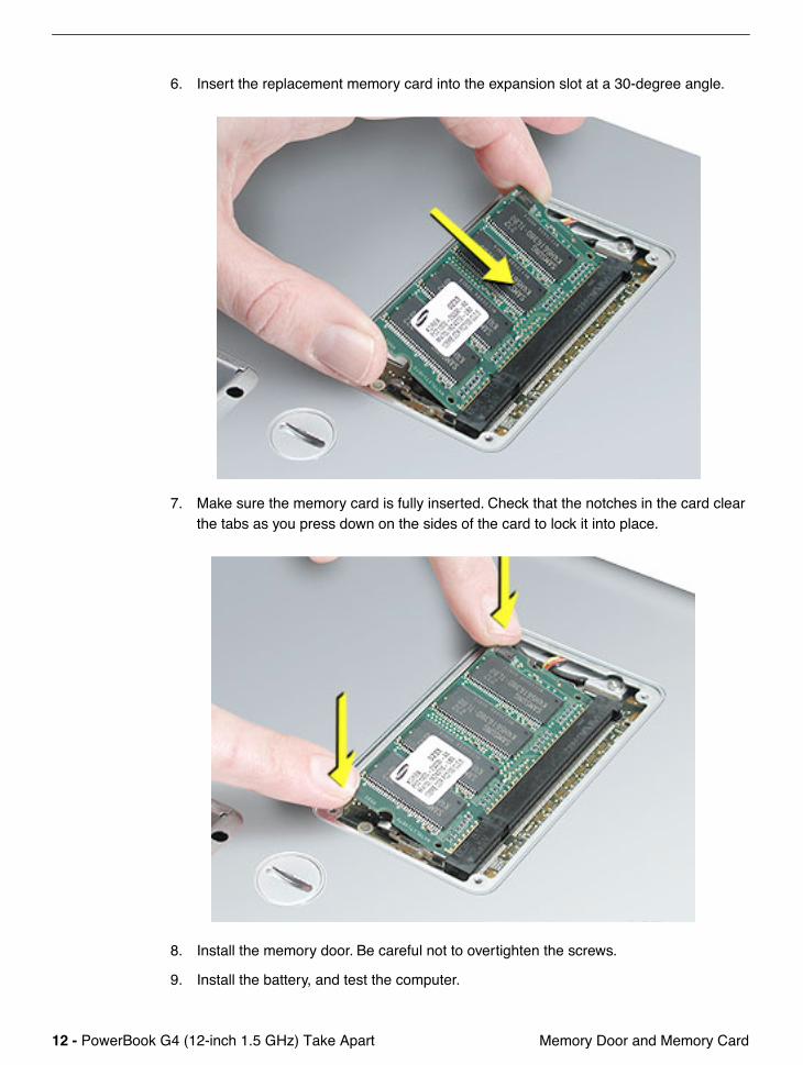
6. Insert the replacement memory card into the expansion slot at a 30-degree angle.
7. Make sure the memory card is fully inserted. Check that the notches in the card clear the tabs as you press down on the sides of the card to lock it into place.
8. Install the memory door. Be careful not to overtighten the screws.
9. Install the battery, and test the computer.
PowerBook G4 (12-inch 1.5 GHz) Take Apart -
13
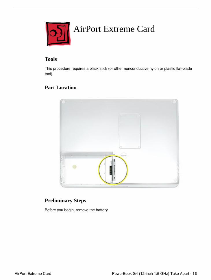
AirPort Extreme Card
AirPort Extreme Card
Tools
This procedure requires a black stick (or other nonconductive nylon or plastic flat-blade tool).
Part Location
Preliminary Steps
Before you begin, remove the battery.
14 -
PowerBook G4 (12-inch 1.5 GHz) Take Apart AirPort Extreme Card
Procedure
Warning:
If the computer has been recently operating, allow it to cool down for 30 minutes before performing this procedure.
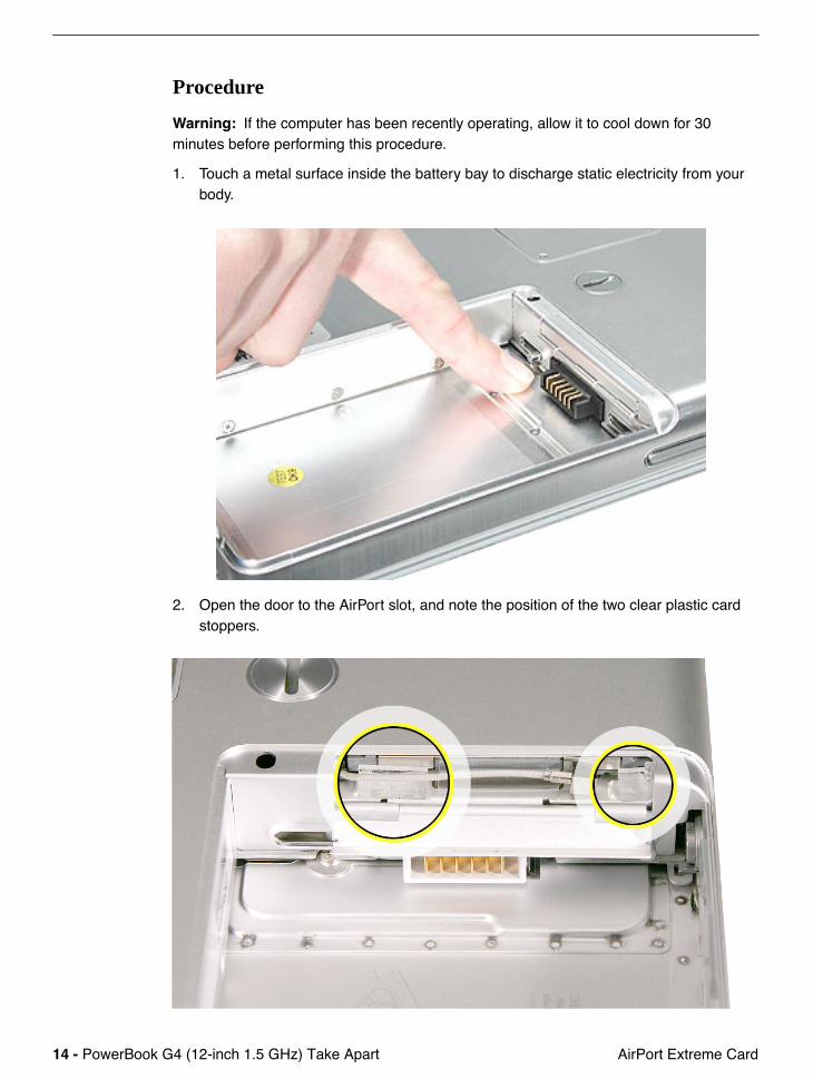
1. Touch a metal surface inside the battery bay to discharge static electricity from your body.
2. Open the door to the AirPort slot, and note the position of the two clear plastic card stoppers.
PowerBook G4 (12-inch 1.5 GHz) Take Apart -
15
AirPort Extreme Card
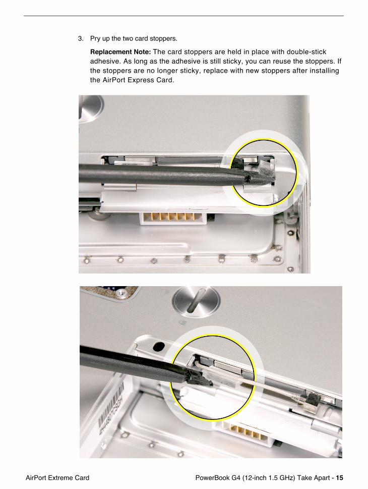
3. Pry up the two card stoppers.
Replacement Note:
The card stoppers are held in place with double-stick adhesive. As long as the adhesive is still sticky, you can reuse the stoppers. If the stoppers are no longer sticky, replace with new stoppers after installing the AirPort Express Card.
16 -
PowerBook G4 (12-inch 1.5 GHz) Take Apart AirPort Extreme Card
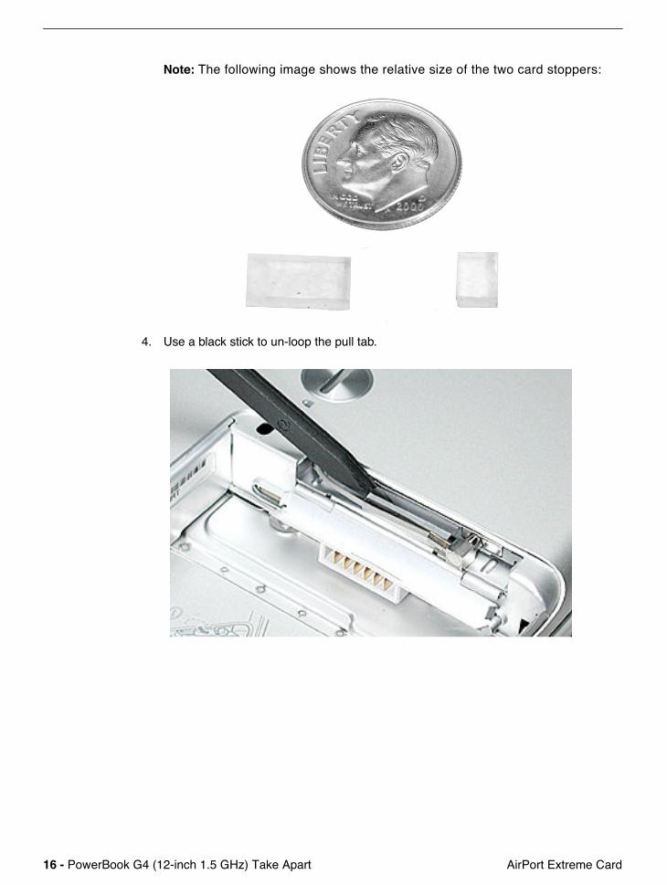
Note:
The following image shows the relative size of the two card stoppers:
4. Use a black stick to un-loop the pull tab.
PowerBook G4 (12-inch 1.5 GHz) Take Apart -
17
AirPort Extreme Card
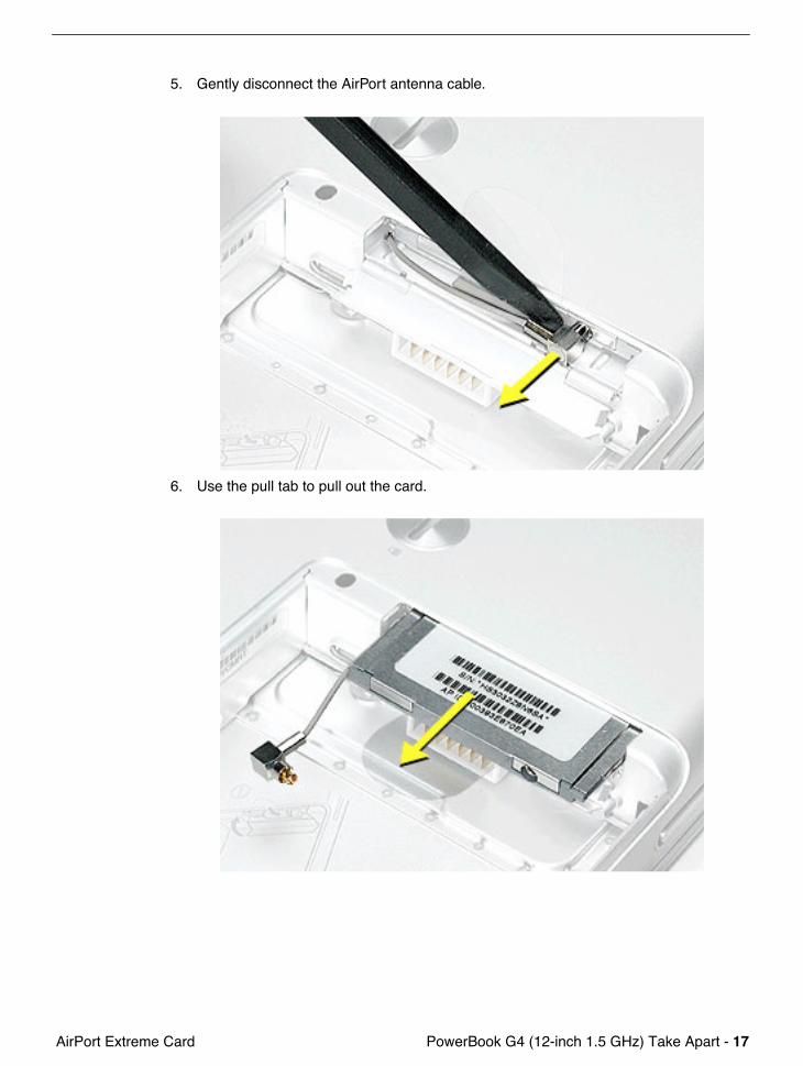
5. Gently disconnect the AirPort antenna cable.
6. Use the pull tab to pull out the card.
18 -
PowerBook G4 (12-inch 1.5 GHz) Take Apart AirPort Extreme Card
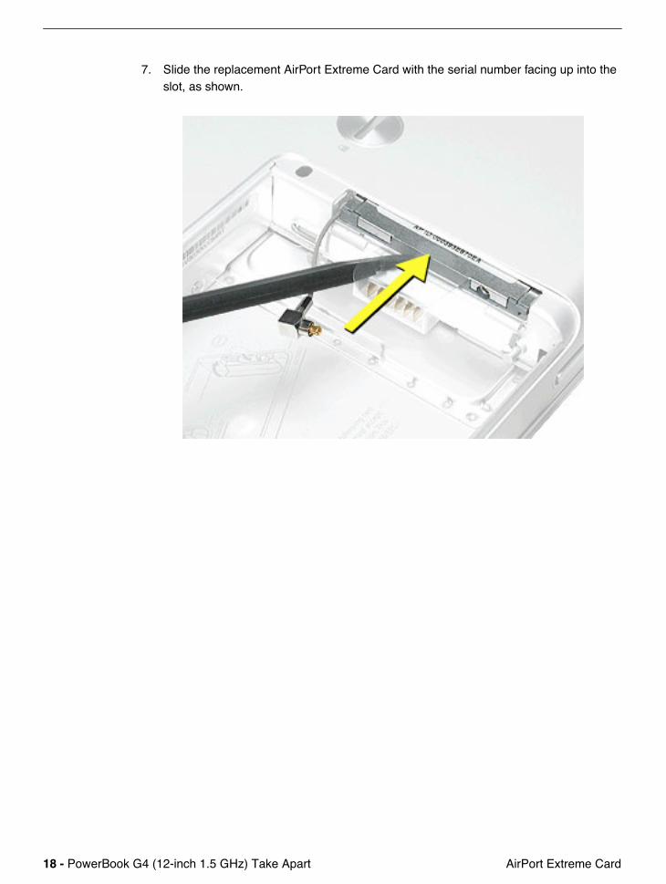
7. Slide the replacement AirPort Extreme Card with the serial number facing up into the slot, as shown.

PowerBook G4 (12-inch 1.5 GHz) Take Apart -
19
AirPort Extreme Card
8. Connect the end of the antenna cable to the card.
9. Loop the clear plastic tab under the card so that the tab secures the antenna cable and tucks into the slot.
Note:
The AirPort slot on the bottom case has a recessed inner slot designed for the clear plastic tab to tuck into.
20 -
PowerBook G4 (12-inch 1.5 GHz) Take Apart AirPort Extreme Card
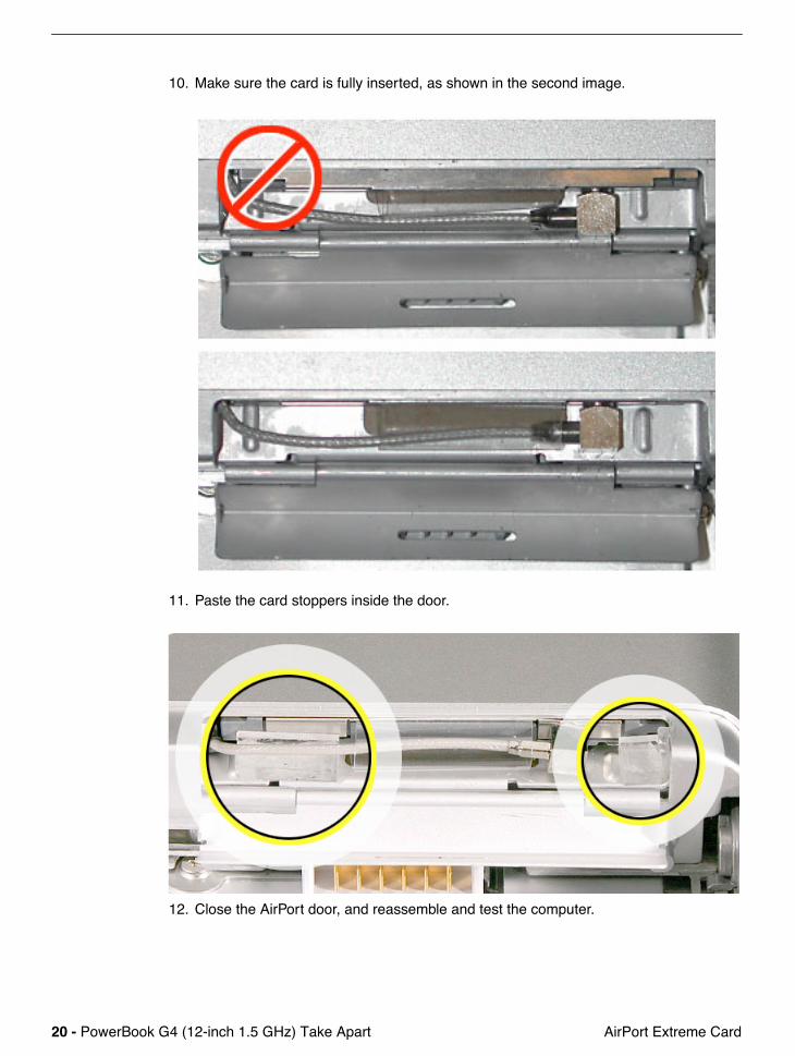
10. Make sure the card is fully inserted, as shown in the second image.
11. Paste the card stoppers inside the door.
12. Close the AirPort door, and reassemble and test the computer.
PowerBook G4 (12-inch 1.5 GHz) Take Apart -
21
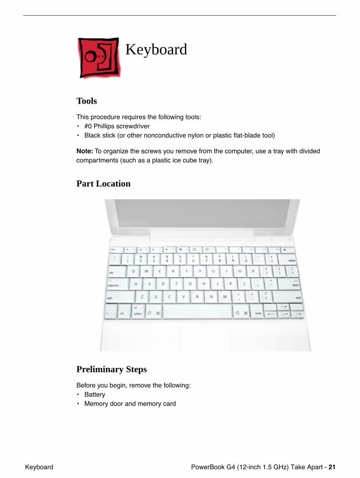
Keyboard
Keyboard
Tools
This procedure requires the following tools:• #0 Phillips screwdriver • Black stick (or other nonconductive nylon or plastic flat-blade tool)
Note:
To organize the screws you remove from the computer, use a tray with divided compartments (such as a plastic ice cube tray).
Part Location
Preliminary Steps
Before you begin, remove the following:• Battery• Memory door and memory card
22 - PowerBook G4 (12-inch 1.5 GHz) Take Apart Keyboard
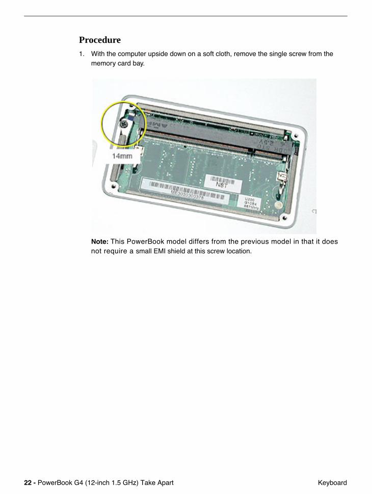
Procedure1. With the computer upside down on a soft cloth, remove the single screw from the
memory card bay.
Note: This PowerBook model differs from the previous model in that it does not require a small EMI shield at this screw location.
PowerBook G4 (12-inch 1.5 GHz) Take Apart - 23 Keyboard
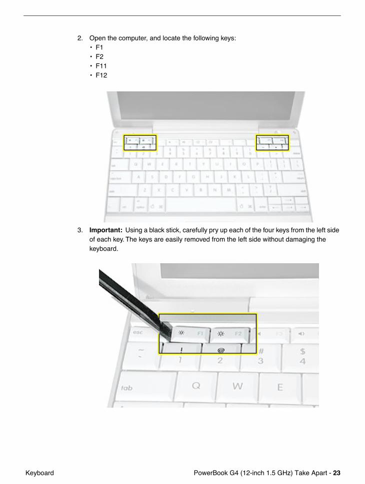
2. Open the computer, and locate the following keys:• F1• F2• F11• F12
3. Important: Using a black stick, carefully pry up each of the four keys from the left side of each key. The keys are easily removed from the left side without damaging the keyboard.
24 - PowerBook G4 (12-inch 1.5 GHz) Take Apart Keyboard
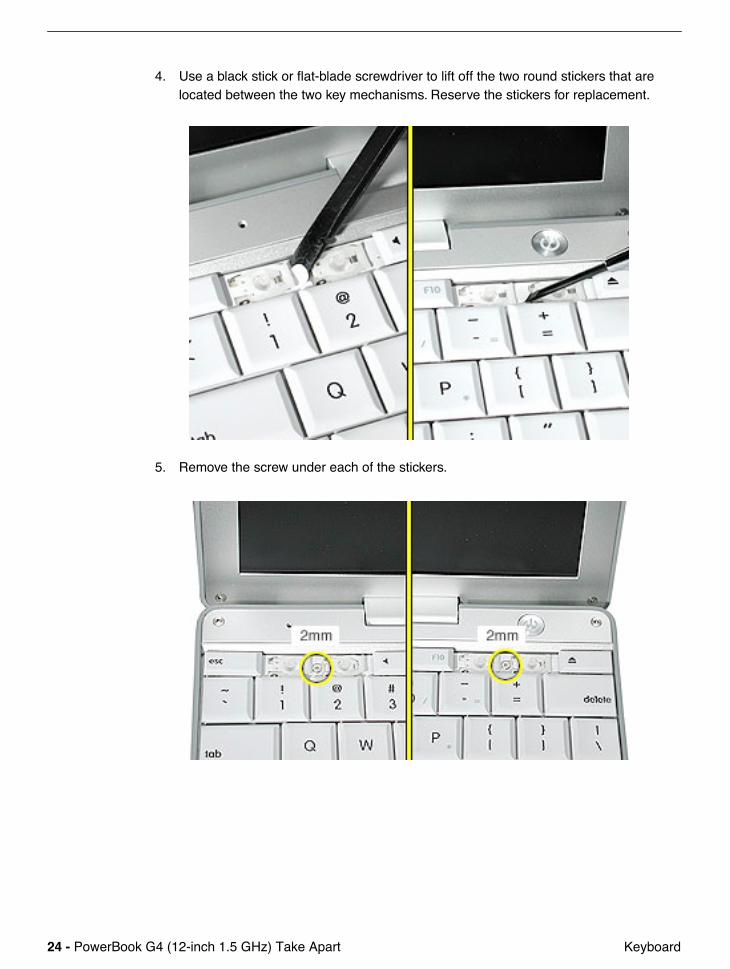
4. Use a black stick or flat-blade screwdriver to lift off the two round stickers that are located between the two key mechanisms. Reserve the stickers for replacement.
5. Remove the screw under each of the stickers.

PowerBook G4 (12-inch 1.5 GHz) Take Apart - 25 Keyboard
6. Lift up the top two corners of the keyboard, and move the keyboard toward the display to clear the tabs at the bottom of the keyboard.
26 - PowerBook G4 (12-inch 1.5 GHz) Take Apart Keyboard
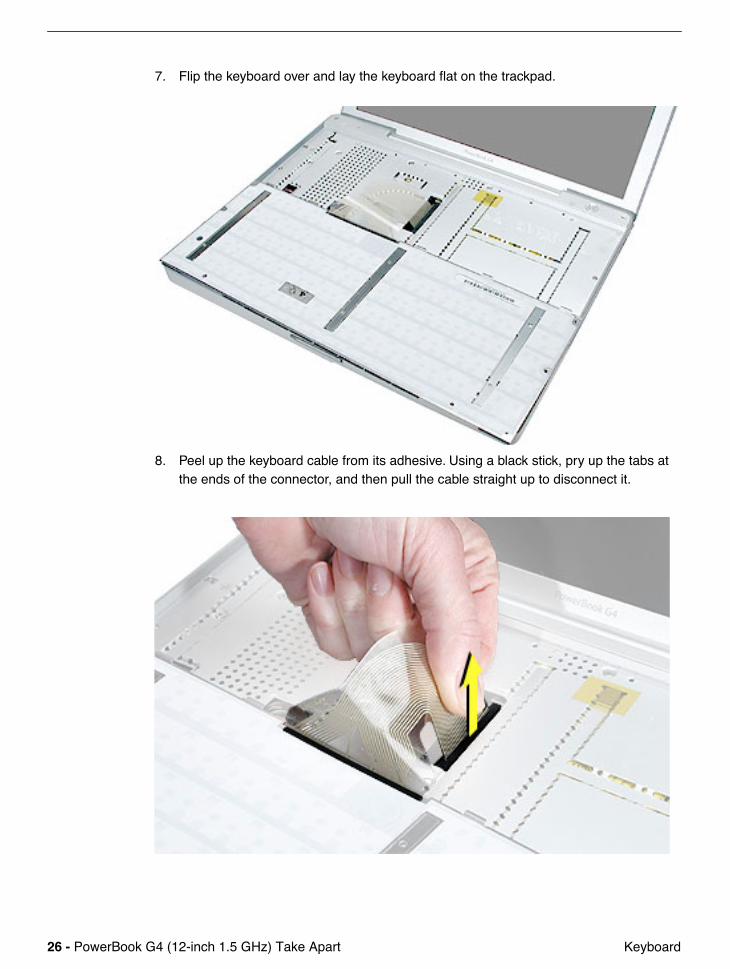
7. Flip the keyboard over and lay the keyboard flat on the trackpad.
8. Peel up the keyboard cable from its adhesive. Using a black stick, pry up the tabs at the ends of the connector, and then pull the cable straight up to disconnect it.
PowerBook G4 (12-inch 1.5 GHz) Take Apart - 27 Keyboard
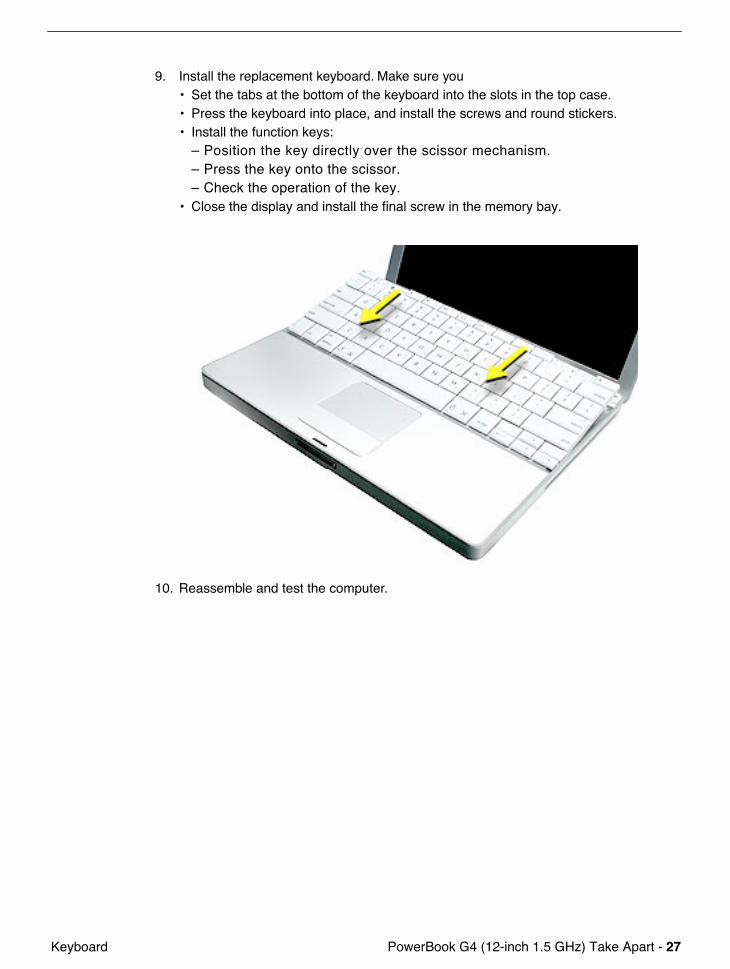
9. Install the replacement keyboard. Make sure you• Set the tabs at the bottom of the keyboard into the slots in the top case.• Press the keyboard into place, and install the screws and round stickers.• Install the function keys:
– Position the key directly over the scissor mechanism.– Press the key onto the scissor.– Check the operation of the key.
• Close the display and install the final screw in the memory bay.
10. Reassemble and test the computer.
28 - PowerBook G4 (12-inch 1.5 GHz) Take Apart Top Case
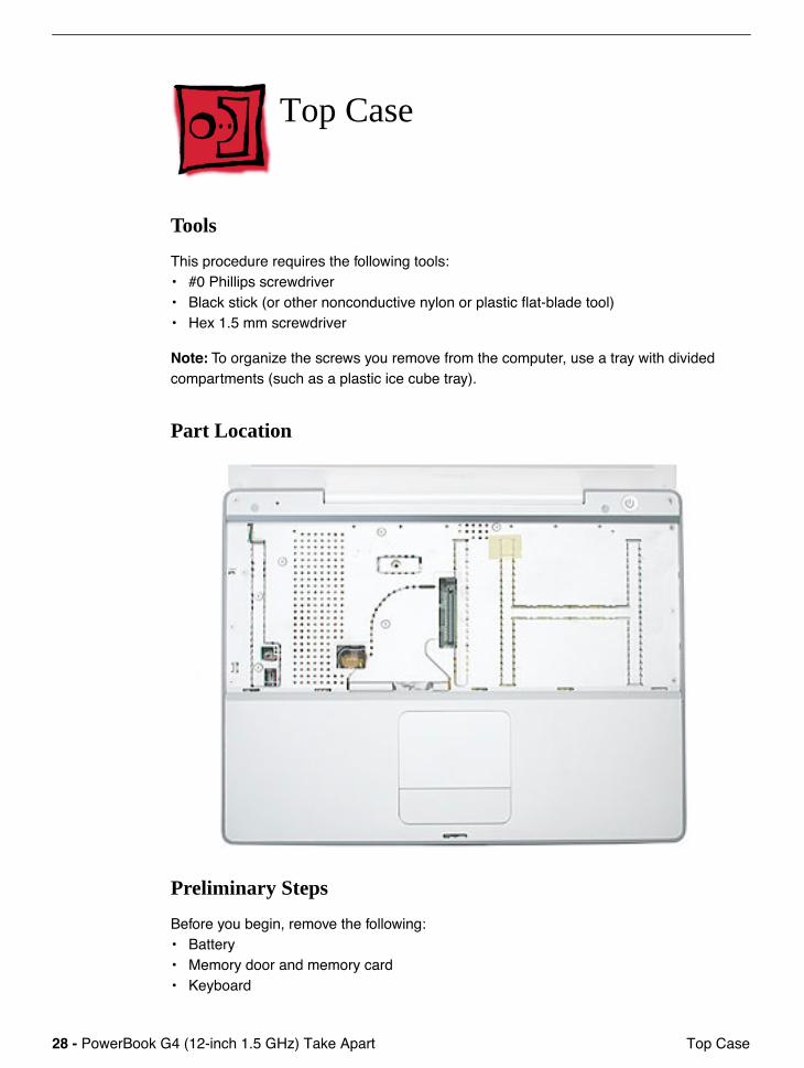
Top Case
Tools
This procedure requires the following tools:• #0 Phillips screwdriver • Black stick (or other nonconductive nylon or plastic flat-blade tool) • Hex 1.5 mm screwdriver
Note: To organize the screws you remove from the computer, use a tray with divided compartments (such as a plastic ice cube tray).
Part Location
Preliminary Steps
Before you begin, remove the following:• Battery• Memory door and memory card• Keyboard
PowerBook G4 (12-inch 1.5 GHz) Take Apart - 29 Top Case
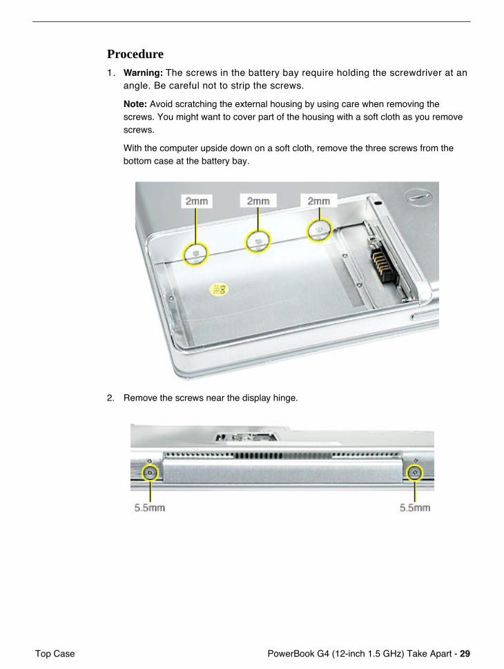
Procedure1. Warning: The screws in the battery bay require holding the screwdriver at an
angle. Be careful not to strip the screws.
Note: Avoid scratching the external housing by using care when removing the screws. You might want to cover part of the housing with a soft cloth as you remove screws.
With the computer upside down on a soft cloth, remove the three screws from the bottom case at the battery bay.
2. Remove the screws near the display hinge.
30 - PowerBook G4 (12-inch 1.5 GHz) Take Apart Top Case
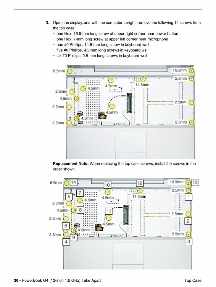
3. Open the display, and with the computer upright, remove the following 14 screws from the top case:• one Hex, 16.5-mm long screw at upper right corner near power button• one Hex, 7-mm long screw at upper left corner near microphone• one #0 Phillips, 14.5-mm long screw in keyboard well• five #0 Phillips, 4.5-mm long screws in keyboard well• six #0 Phillips, 2.5-mm long screws in keyboard well
Replacement Note: When replacing the top case screws, install the screws in the order shown.
PowerBook G4 (12-inch 1.5 GHz) Take Apart - 31 Top Case
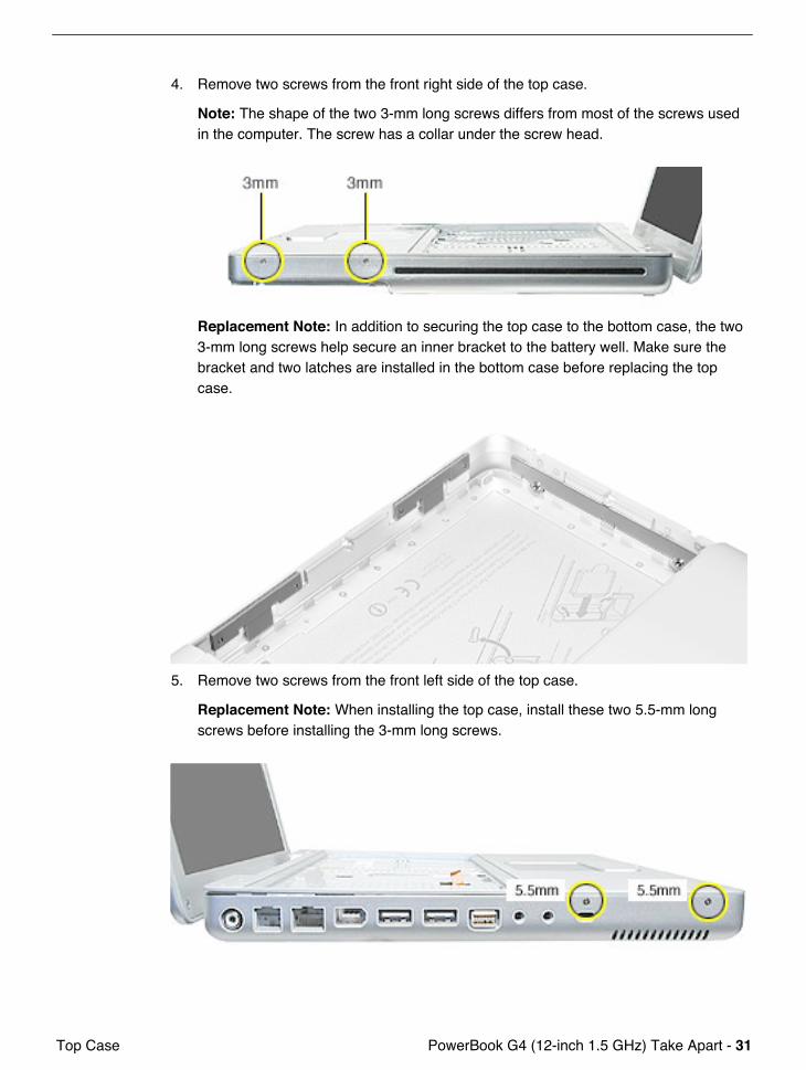
4. Remove two screws from the front right side of the top case.
Note: The shape of the two 3-mm long screws differs from most of the screws used in the computer. The screw has a collar under the screw head.
Replacement Note: In addition to securing the top case to the bottom case, the two 3-mm long screws help secure an inner bracket to the battery well. Make sure the bracket and two latches are installed in the bottom case before replacing the top case.
5. Remove two screws from the front left side of the top case.
Replacement Note: When installing the top case, install these two 5.5-mm long screws before installing the 3-mm long screws.
32 - PowerBook G4 (12-inch 1.5 GHz) Take Apart Top Case
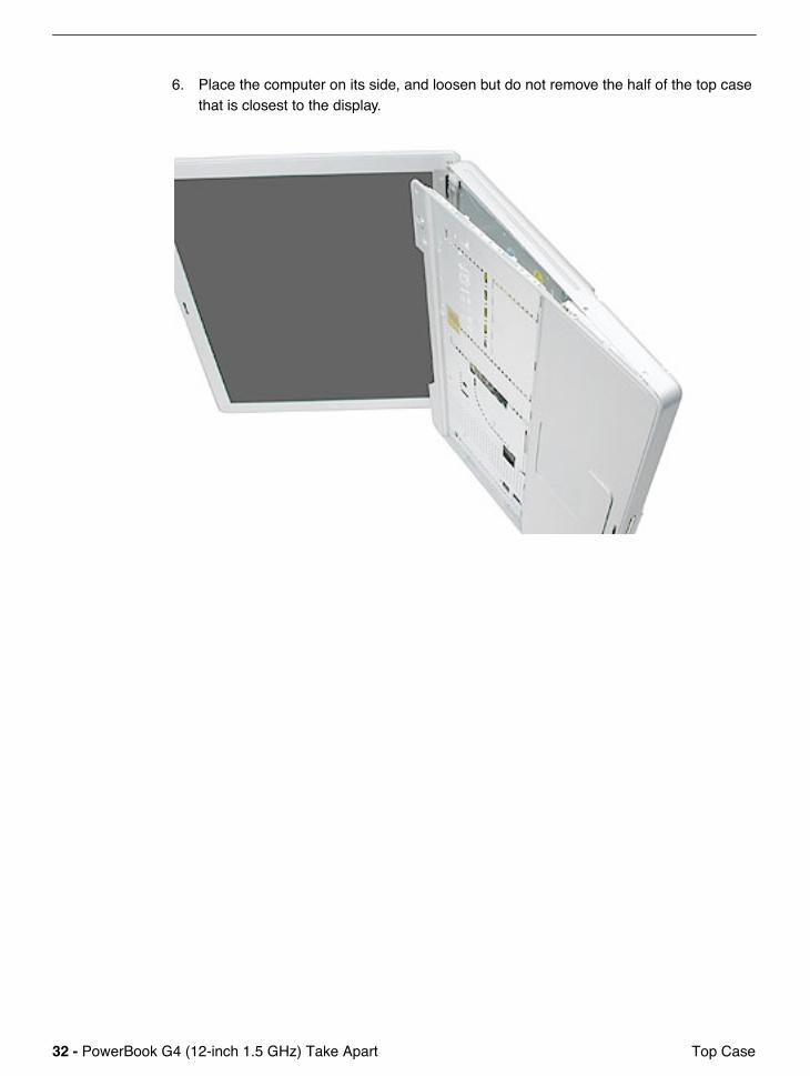
6. Place the computer on its side, and loosen but do not remove the half of the top case that is closest to the display.

PowerBook G4 (12-inch 1.5 GHz) Take Apart - 33 Top Case
7. At the battery bay, note the two plastic latches that hold the top case to the bottom case.
8. Use a black stick to release both latches.
34 - PowerBook G4 (12-inch 1.5 GHz) Take Apart Top Case
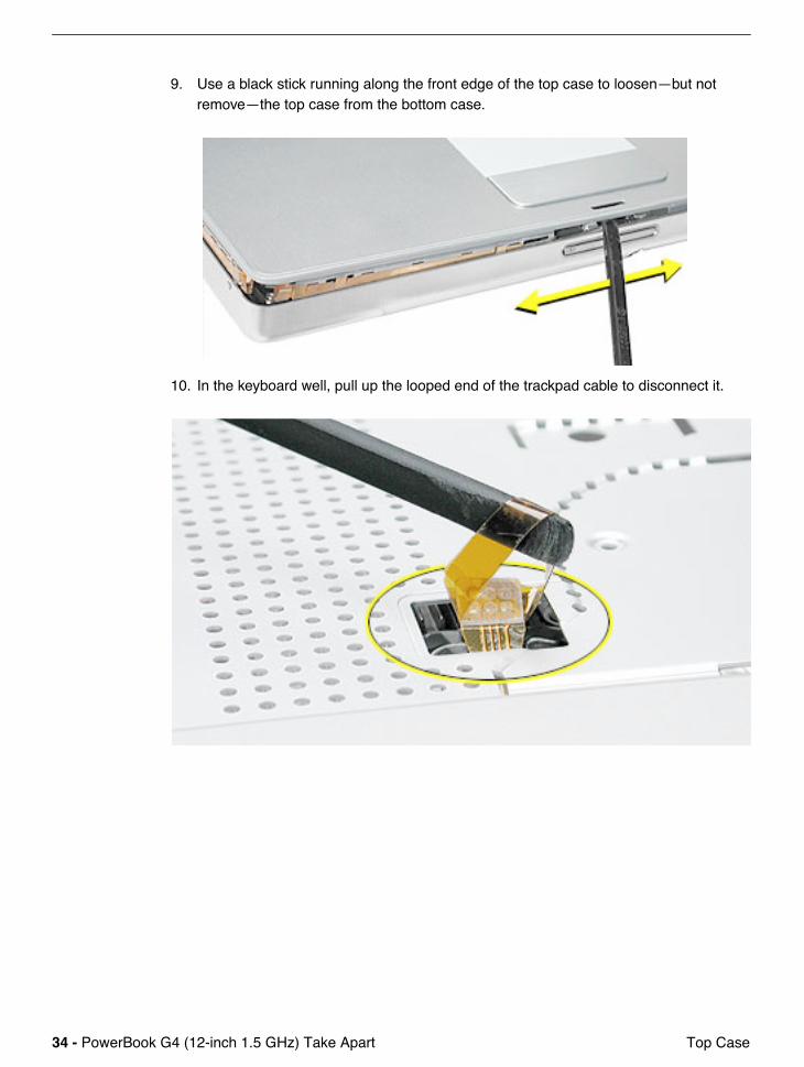
9. Use a black stick running along the front edge of the top case to loosen—but not remove—the top case from the bottom case.
10. In the keyboard well, pull up the looped end of the trackpad cable to disconnect it.
PowerBook G4 (12-inch 1.5 GHz) Take Apart - 35 Top Case
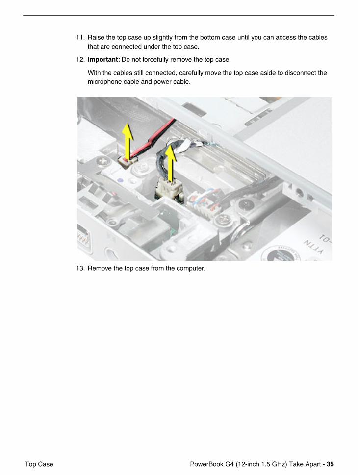
11. Raise the top case up slightly from the bottom case until you can access the cables that are connected under the top case.
12. Important: Do not forcefully remove the top case.
With the cables still connected, carefully move the top case aside to disconnect the microphone cable and power cable.
13. Remove the top case from the computer.
36 - PowerBook G4 (12-inch 1.5 GHz) Take Apart Top Case
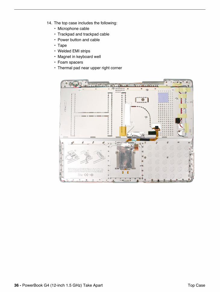
14. The top case includes the following:• Microphone cable• Trackpad and trackpad cable• Power button and cable• Tape• Welded EMI strips• Magnet in keyboard well• Foam spacers• Thermal pad near upper right corner
PowerBook G4 (12-inch 1.5 GHz) Take Apart - 37 Top Case
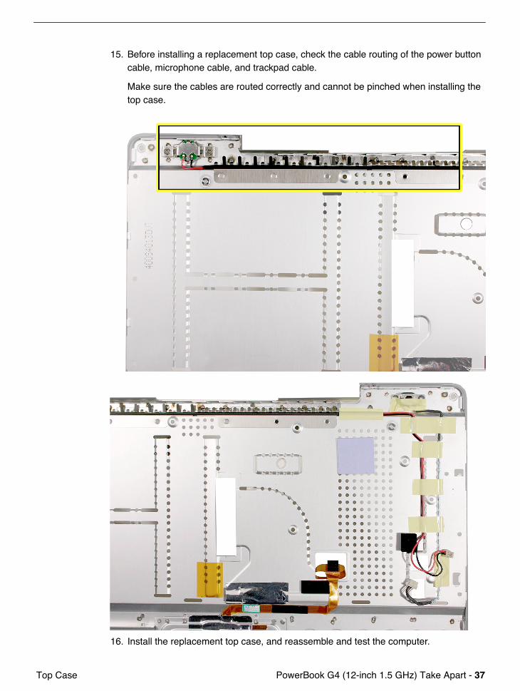
15. Before installing a replacement top case, check the cable routing of the power button cable, microphone cable, and trackpad cable.
Make sure the cables are routed correctly and cannot be pinched when installing the top case.
16. Install the replacement top case, and reassemble and test the computer.
38 - PowerBook G4 (12-inch 1.5 GHz) Take Apart Hall Effect Sensor Board and Cable
Hall Effect Sensor Board and Cable
Tools
This procedure requires the following tools:• Phillips #0 screwdriver• Black stick (or other nonconductive nylon or plastic flat-blade tool)
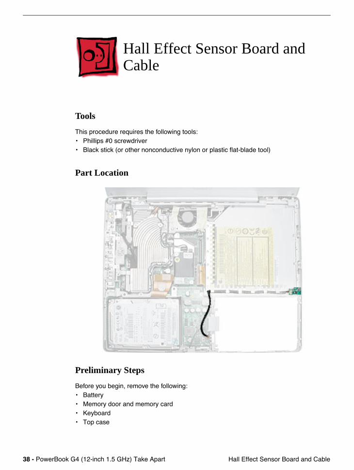
Part Location
Preliminary Steps
Before you begin, remove the following:• Battery• Memory door and memory card • Keyboard• Top case
PowerBook G4 (12-inch 1.5 GHz) Take Apart - 39 Hall Effect Sensor Board and Cable
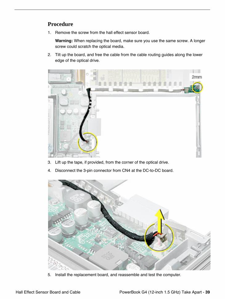
Procedure1. Remove the screw from the hall effect sensor board.
Warning: When replacing the board, make sure you use the same screw. A longer screw could scratch the optical media.
2. Tilt up the board, and free the cable from the cable routing guides along the lower edge of the optical drive.
3. Lift up the tape, if provided, from the corner of the optical drive.
4. Disconnect the 3-pin connector from CN4 at the DC-to-DC board.
5. Install the replacement board, and reassemble and test the computer.
40 - PowerBook G4 (12-inch 1.5 GHz) Take Apart Hall Effect Sensor Board and Cable
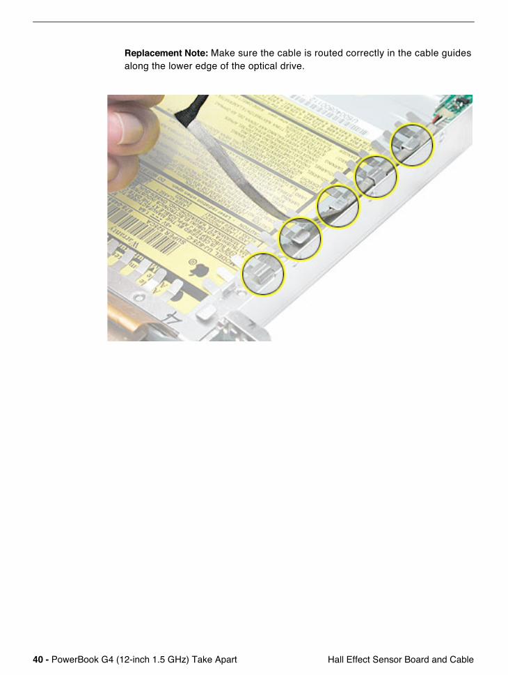
Replacement Note: Make sure the cable is routed correctly in the cable guides along the lower edge of the optical drive.
PowerBook G4 (12-inch 1.5 GHz) Take Apart - 41 Hard Drive
Hard Drive
Tools
This procedure requires the following tools:• #0 Phillips screwdriver • Black stick (or other nonconductive nylon or plastic flat-blade tool)
Note: To organize the screws you remove from the computer, use a tray with divided compartments (such as a plastic ice cube tray).
Part Location
Preliminary Steps
Before you begin, remove the following:• Battery• Memory door and memory card

42 - PowerBook G4 (12-inch 1.5 GHz) Take Apart Hard Drive
• Keyboard• Top case
Procedure1. Disconnect the hard drive flex cable.
2. Remove two screws from the hard drive bracket.
PowerBook G4 (12-inch 1.5 GHz) Take Apart - 43 Hard Drive
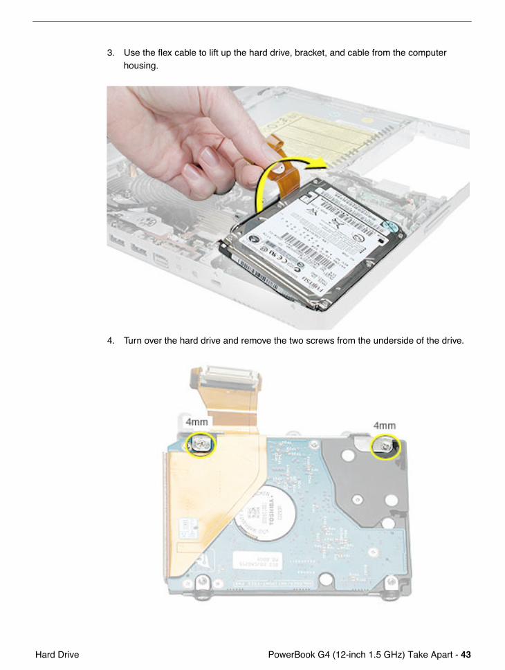
3. Use the flex cable to lift up the hard drive, bracket, and cable from the computer housing.
4. Turn over the hard drive and remove the two screws from the underside of the drive.
44 - PowerBook G4 (12-inch 1.5 GHz) Take Apart Hard Drive
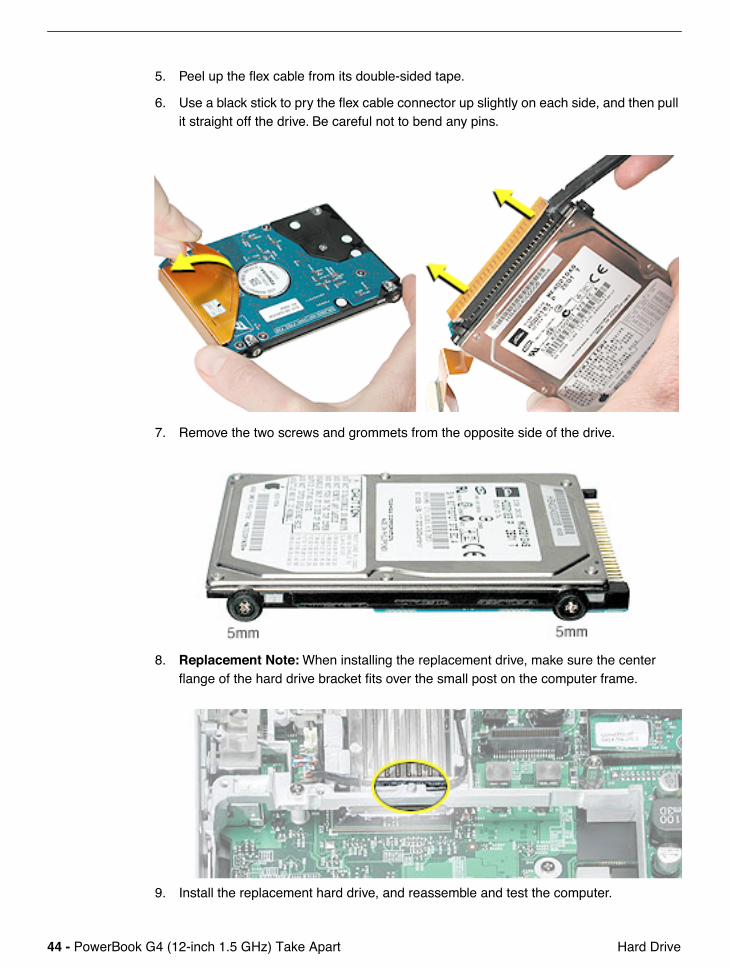
5. Peel up the flex cable from its double-sided tape.
6. Use a black stick to pry the flex cable connector up slightly on each side, and then pull it straight off the drive. Be careful not to bend any pins.
7. Remove the two screws and grommets from the opposite side of the drive.
8. Replacement Note: When installing the replacement drive, make sure the center flange of the hard drive bracket fits over the small post on the computer frame.
9. Install the replacement hard drive, and reassemble and test the computer.

PowerBook G4 (12-inch 1.5 GHz) Take Apart - 45 Modem
Modem
Tools
This procedure requires the following tools:• #0 Phillips screwdriver • Black stick (or other nonconductive nylon or plastic flat-blade tool)
Part Location
Preliminary Steps
Before you begin, remove the following:• Battery• Memory door and memory card• Keyboard• Top case
46 - PowerBook G4 (12-inch 1.5 GHz) Take Apart Modem
Procedure1. Warning: When removing the modem, be careful not to strain the modem cable
or shield. Do not apply pressure to the modem. Read all of the procedure before removing and replacing the modem.
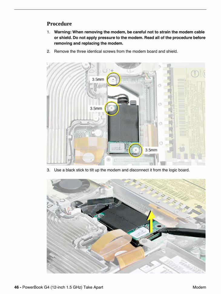
2. Remove the three identical screws from the modem board and shield.
3. Use a black stick to tilt up the modem and disconnect it from the logic board.

PowerBook G4 (12-inch 1.5 GHz) Take Apart - 47 Modem
4. Tilt up the modem board and shield.
5. Disconnect the modem cable.
48 - PowerBook G4 (12-inch 1.5 GHz) Take Apart Modem
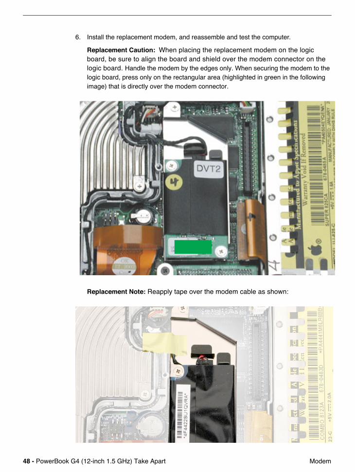
6. Install the replacement modem, and reassemble and test the computer.
Replacement Caution: When placing the replacement modem on the logic board, be sure to align the board and shield over the modem connector on the logic board. Handle the modem by the edges only. When securing the modem to the logic board, press only on the rectangular area (highlighted in green in the following image) that is directly over the modem connector.
Replacement Note: Reapply tape over the modem cable as shown:
PowerBook G4 (12-inch 1.5 GHz) Take Apart - 49 DC-to-DC Board
DC-to-DC Board
Tools
This procedure requires the following tools:• #0 Phillips screwdriver (magnetized preferred)• Black stick (or other nonconductive nylon or plastic flat-blade tool)• 4 mm socket wrench or needlenose pliers
Note: To organize the screws you remove from the computer, use a tray with divided compartments (such as a plastic ice cube tray).
Part Location
50 - PowerBook G4 (12-inch 1.5 GHz) Take Apart DC-to-DC Board
Preliminary Steps
Before you begin, remove the following:• Battery• Memory door and memory card• Keyboard• Top case• Hard drive
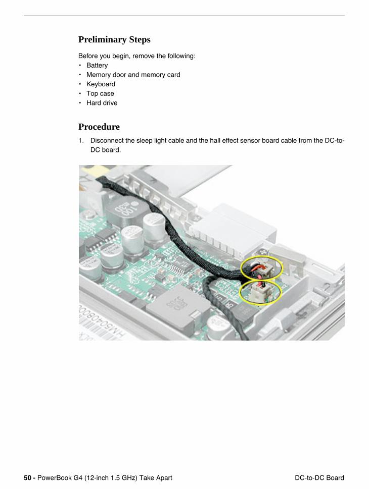
Procedure1. Disconnect the sleep light cable and the hall effect sensor board cable from the DC-to-
DC board.
PowerBook G4 (12-inch 1.5 GHz) Take Apart - 51 DC-to-DC Board
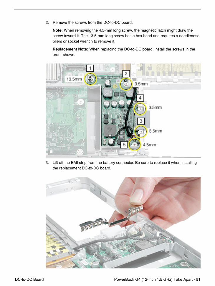
2. Remove the screws from the DC-to-DC board.
Note: When removing the 4.5-mm long screw, the magnetic latch might draw the screw toward it. The 13.5-mm long screw has a hex head and requires a needlenose pliers or socket wrench to remove it.
Replacement Note: When replacing the DC-to-DC board, install the screws in the order shown.
3. Lift off the EMI strip from the battery connector. Be sure to replace it when installing the replacement DC-to-DC board.

52 - PowerBook G4 (12-inch 1.5 GHz) Take Apart DC-to-DC Board
4. Place a black stick just under the top edge of the board. Do not lean the black stick on the modem board or optical drive. Disconnect the DC-to-DC board from the logic board by prying up the DC-to-DC board and removing it from the computer assembly.
5. Install the replacement DC-to-DC board, and reassemble and test the computer.
PowerBook G4 (12-inch 1.5 GHz) Take Apart - 53 Heatsink and Fan Assembly
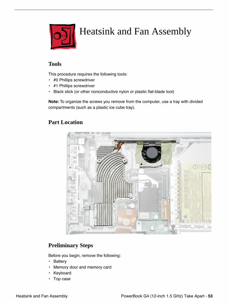
Heatsink and Fan Assembly
Tools
This procedure requires the following tools:• #0 Phillips screwdriver • #1 Phillips screwdriver• Black stick (or other nonconductive nylon or plastic flat-blade tool)
Note: To organize the screws you remove from the computer, use a tray with divided compartments (such as a plastic ice cube tray).
Part Location
Preliminary Steps
Before you begin, remove the following:• Battery• Memory door and memory card • Keyboard• Top case
54 - PowerBook G4 (12-inch 1.5 GHz) Take Apart Heatsink and Fan Assembly
Procedure1. Warning: The cone of the subwoofer, located below the heatsink and to the right of
the fan, is a sensitive device. Avoid touching the subwoofer cone as you perform this procedure.
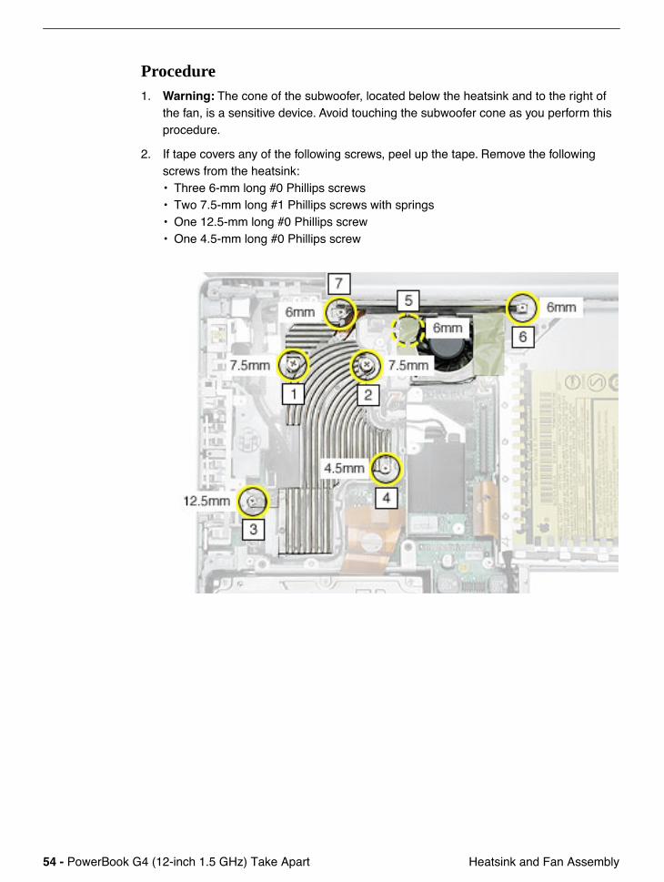
2. If tape covers any of the following screws, peel up the tape. Remove the following screws from the heatsink:• Three 6-mm long #0 Phillips screws• Two 7.5-mm long #1 Phillips screws with springs• One 12.5-mm long #0 Phillips screw• One 4.5-mm long #0 Phillips screw
PowerBook G4 (12-inch 1.5 GHz) Take Apart - 55 Heatsink and Fan Assembly
3. Remove the tape, if provided, that covers the heatsink and secures the cables in place.
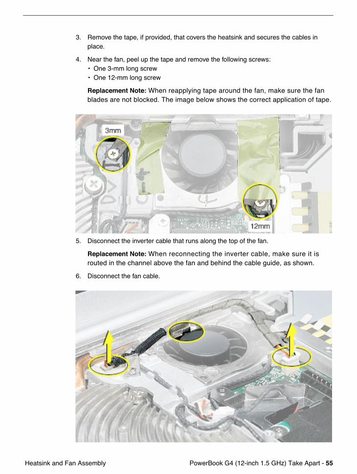
4. Near the fan, peel up the tape and remove the following screws:• One 3-mm long screw• One 12-mm long screw
Replacement Note: When reapplying tape around the fan, make sure the fan blades are not blocked. The image below shows the correct application of tape.
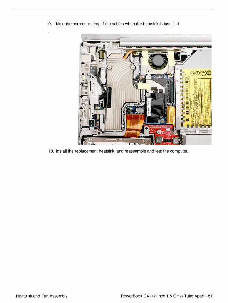
5. Disconnect the inverter cable that runs along the top of the fan.
Replacement Note: When reconnecting the inverter cable, make sure it is routed in the channel above the fan and behind the cable guide, as shown.
6. Disconnect the fan cable.

56 - PowerBook G4 (12-inch 1.5 GHz) Take Apart Heatsink and Fan Assembly
7. Holding the heatsink plate, begin to lift up the heatsink assembly, being careful where it catches on remaining tape and the chassis. Use a black stick to pry up the middle right corner of the heatsink plate.
Warning: To avoid bending the heatsink, support the heatsink as it is removed.
8. Note the placement of the thermal pads. Make sure you replace the thermal pads whenever the heatsink is removed or replaced.
PowerBook G4 (12-inch 1.5 GHz) Take Apart - 57 Heatsink and Fan Assembly
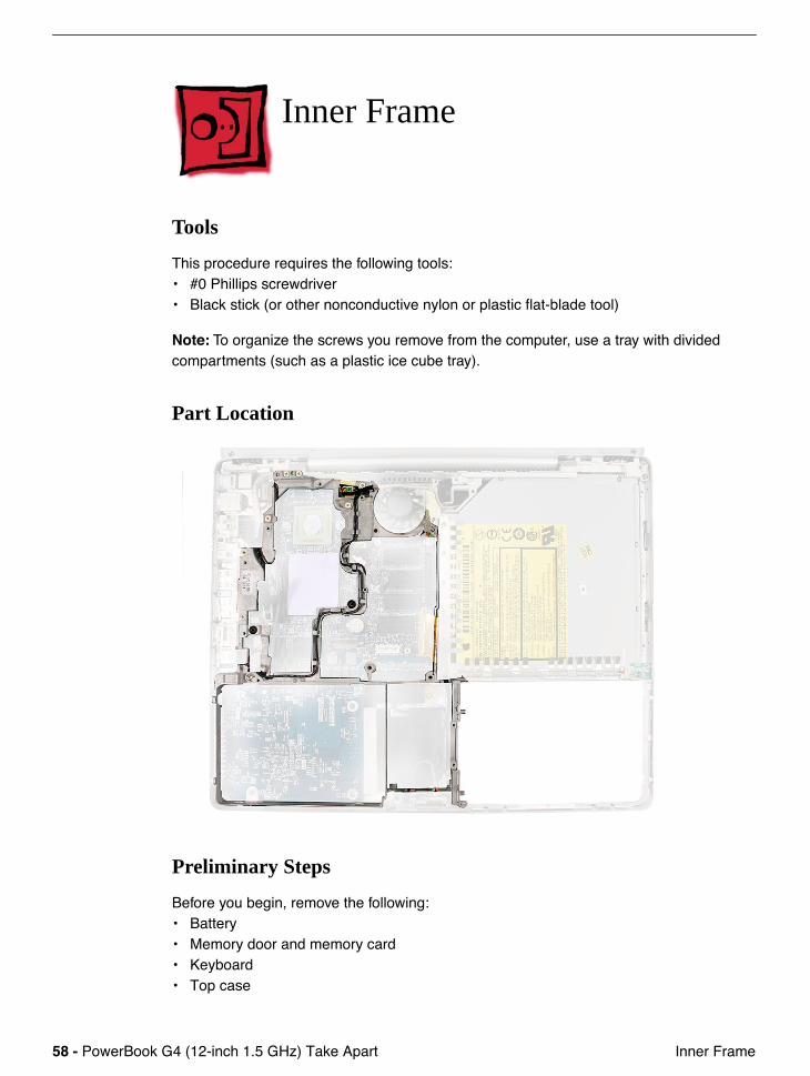
9. Note the correct routing of the cables when the heatsink is installed.
.
10. Install the replacement heatsink, and reassemble and test the computer.
58 - PowerBook G4 (12-inch 1.5 GHz) Take Apart Inner Frame
Inner Frame
Tools
This procedure requires the following tools:• #0 Phillips screwdriver • Black stick (or other nonconductive nylon or plastic flat-blade tool)
Note: To organize the screws you remove from the computer, use a tray with divided compartments (such as a plastic ice cube tray).
Part Location
Preliminary Steps
Before you begin, remove the following:• Battery• Memory door and memory card• Keyboard• Top case
PowerBook G4 (12-inch 1.5 GHz) Take Apart - 59 Inner Frame
• Hard drive• Modem• DC-to-DC board• Heatsink
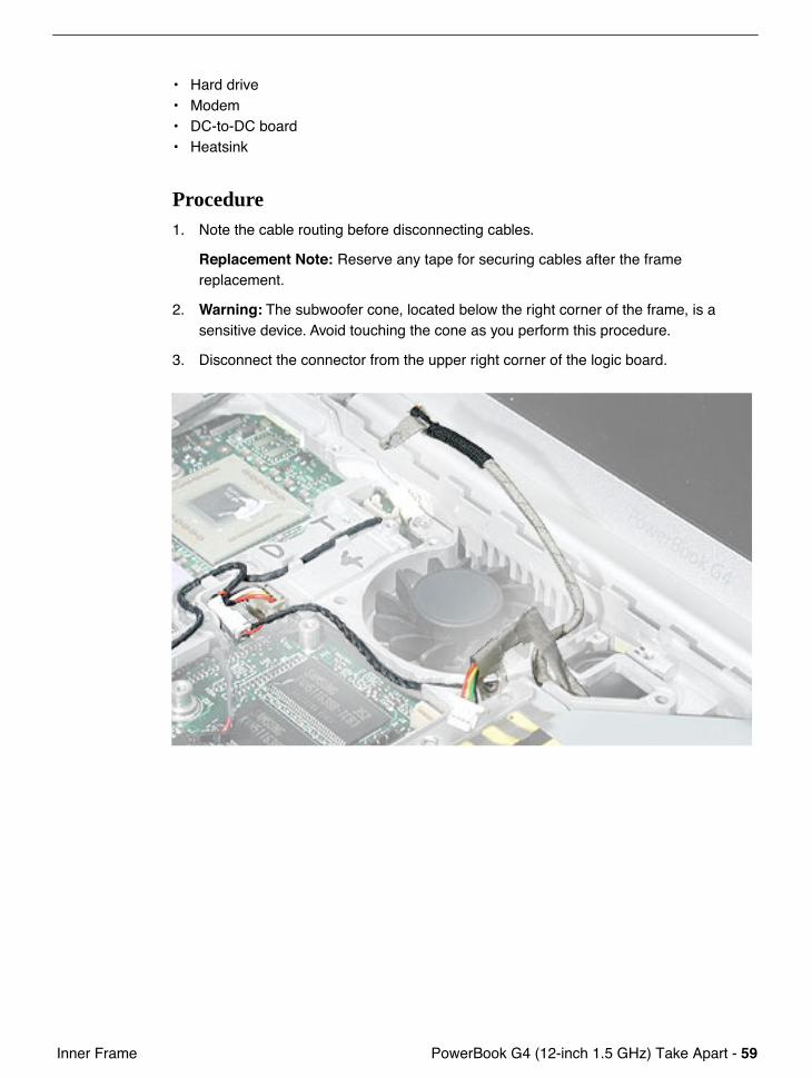
Procedure1. Note the cable routing before disconnecting cables.
Replacement Note: Reserve any tape for securing cables after the frame replacement.
2. Warning: The subwoofer cone, located below the right corner of the frame, is a sensitive device. Avoid touching the cone as you perform this procedure.
3. Disconnect the connector from the upper right corner of the logic board.
60 - PowerBook G4 (12-inch 1.5 GHz) Take Apart Inner Frame
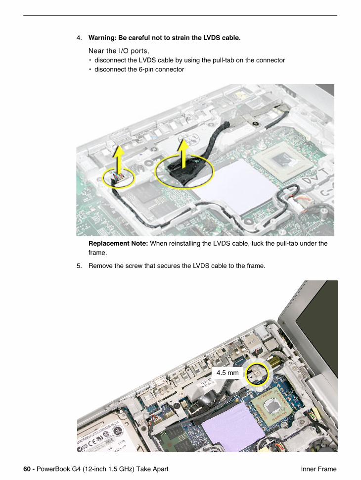
4. Warning: Be careful not to strain the LVDS cable.
Near the I/O ports, • disconnect the LVDS cable by using the pull-tab on the connector• disconnect the 6-pin connector
Replacement Note: When reinstalling the LVDS cable, tuck the pull-tab under the frame.
5. Remove the screw that secures the LVDS cable to the frame.
PowerBook G4 (12-inch 1.5 GHz) Take Apart - 61 Inner Frame
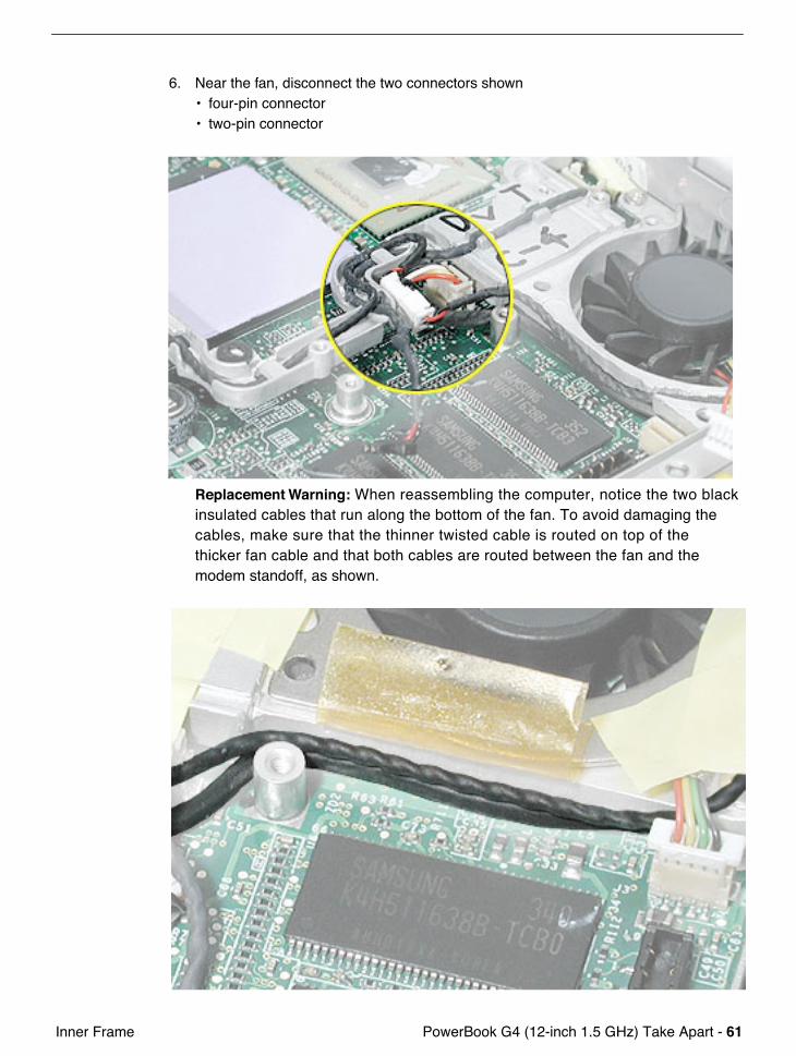
6. Near the fan, disconnect the two connectors shown• four-pin connector• two-pin connector
Replacement Warning: When reassembling the computer, notice the two black insulated cables that run along the bottom of the fan. To avoid damaging the cables, make sure that the thinner twisted cable is routed on top of the thicker fan cable and that both cables are routed between the fan and the modem standoff, as shown.
62 - PowerBook G4 (12-inch 1.5 GHz) Take Apart Inner Frame
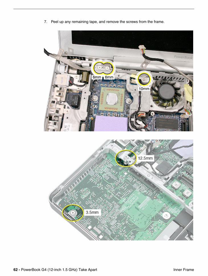
7. Peel up any remaining tape, and remove the screws from the frame.
PowerBook G4 (12-inch 1.5 GHz) Take Apart - 63 Inner Frame
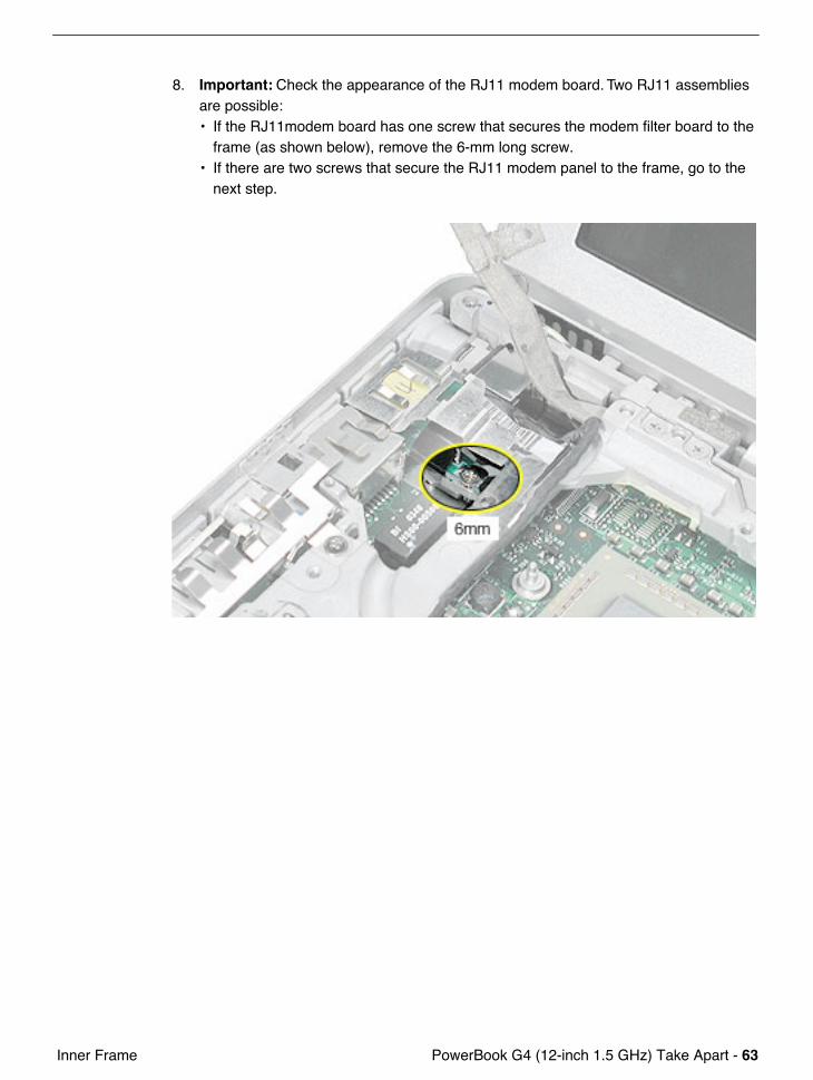
8. Important: Check the appearance of the RJ11 modem board. Two RJ11 assemblies are possible:• If the RJ11modem board has one screw that secures the modem filter board to the
frame (as shown below), remove the 6-mm long screw. • If there are two screws that secure the RJ11 modem panel to the frame, go to the
next step.
64 - PowerBook G4 (12-inch 1.5 GHz) Take Apart Inner Frame
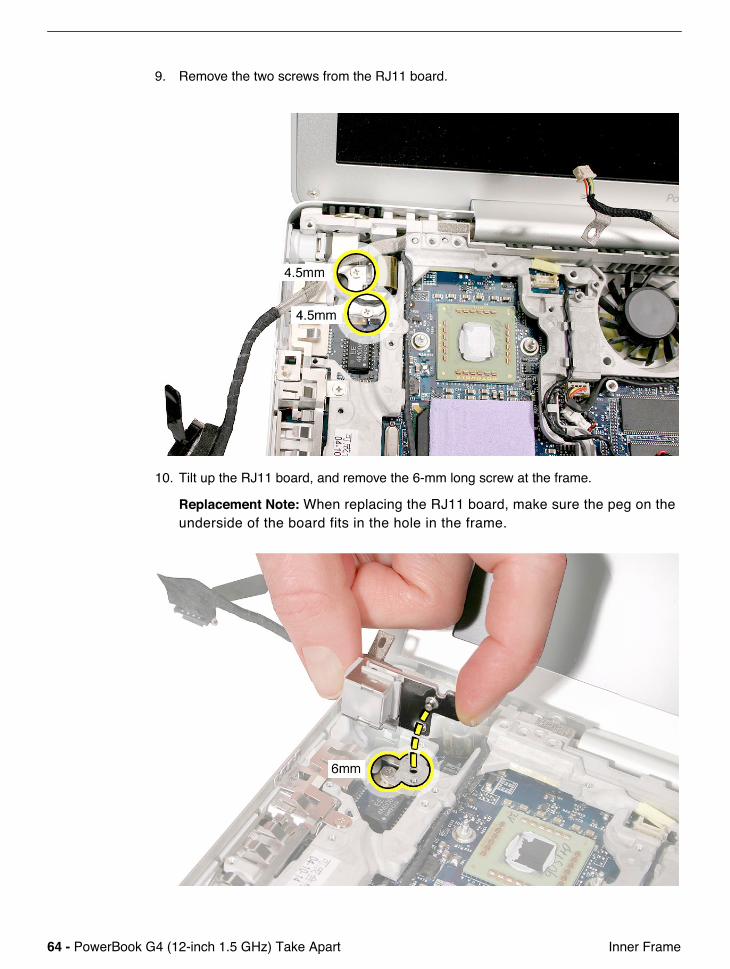
9. Remove the two screws from the RJ11 board.
10. Tilt up the RJ11 board, and remove the 6-mm long screw at the frame.
Replacement Note: When replacing the RJ11 board, make sure the peg on the underside of the board fits in the hole in the frame.
PowerBook G4 (12-inch 1.5 GHz) Take Apart - 65 Inner Frame
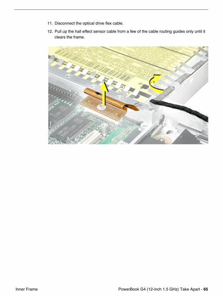
11. Disconnect the optical drive flex cable.
12. Pull up the hall effect sensor cable from a few of the cable routing guides only until it clears the frame.
66 - PowerBook G4 (12-inch 1.5 GHz) Take Apart Inner Frame
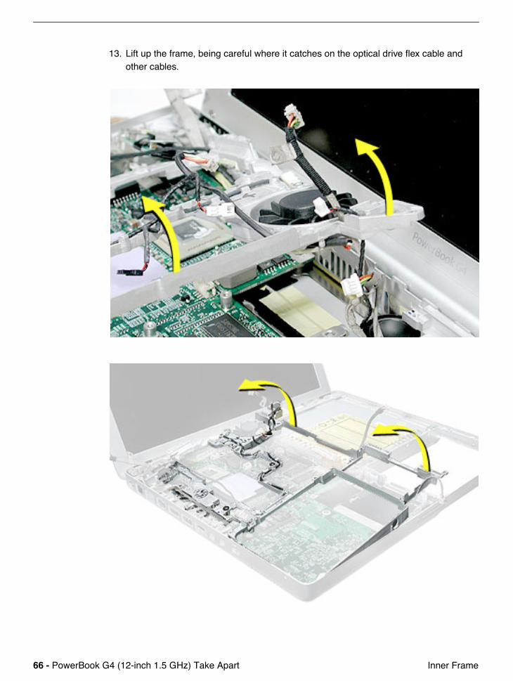
13. Lift up the frame, being careful where it catches on the optical drive flex cable and other cables.
PowerBook G4 (12-inch 1.5 GHz) Take Apart - 67 Inner Frame
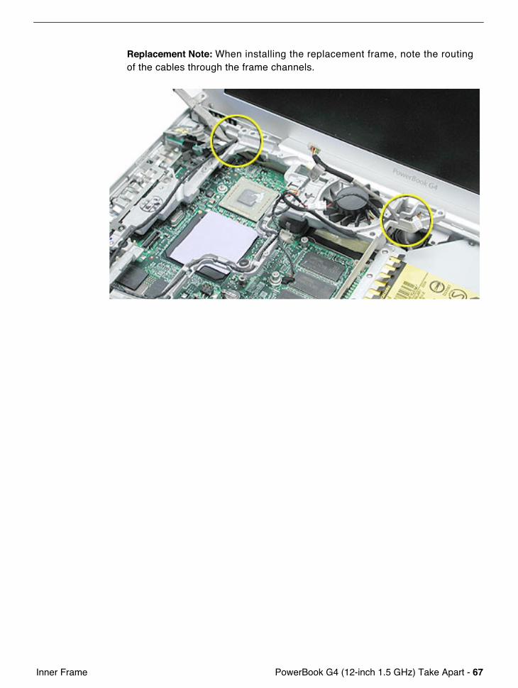
Replacement Note: When installing the replacement frame, note the routing of the cables through the frame channels.
68 - PowerBook G4 (12-inch 1.5 GHz) Take Apart Inner Frame
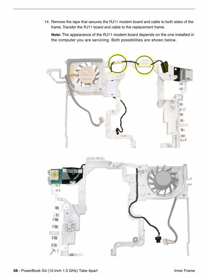
14. Remove the tape that secures the RJ11 modem board and cable to both sides of the frame. Transfer the RJ11 board and cable to the replacement frame.
Note: The appearance of the RJ11 modem board depends on the one installed in the computer you are servicing. Both possibilities are shown below.

PowerBook G4 (12-inch 1.5 GHz) Take Apart - 69 Inner Frame
15. Remove the screws that secure the EMI strip to the frame. Transfer the EMI strip to the replacement frame.
16. Remove the screws from the fan. Transfer the fan to the replacement frame. (Refer to "Fan" in this chapter.)
Replacement Note: Check that the replacement frame includes a thermal pad next to the fan, as shown by the blue rectangle in the following image.
17. Install the replacement frame, and reassemble and test the computer.
70 - PowerBook G4 (12-inch 1.5 GHz) Take Apart RJ11 Modem Board and Cable
RJ11 Modem Board and Cable
Tools
This procedure requires the following tools:• #0 Phillips screwdriver • Black stick (or other nonconductive nylon or plastic flat-blade tool)
Note: To organize the screws you remove from the computer, use a tray with divided compartments (such as a plastic ice cube tray).
Part Location
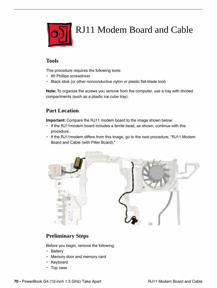
Important: Compare the RJ11 modem board to the image shown below:• If the RJ11modem board includes a ferrite bead, as shown, continue with this
procedure. • If the RJ11modem differs from this image, go to the next procedure, "RJ11 Modem
Board and Cable (with Filter Board)."
Preliminary Steps
Before you begin, remove the following:• Battery• Memory door and memory card• Keyboard• Top case
PowerBook G4 (12-inch 1.5 GHz) Take Apart - 71 RJ11 Modem Board and Cable
• Hall effect sensor board and cable• Hard drive• Modem• DC-to-DC board• Heatsink with fan• Inner Frame
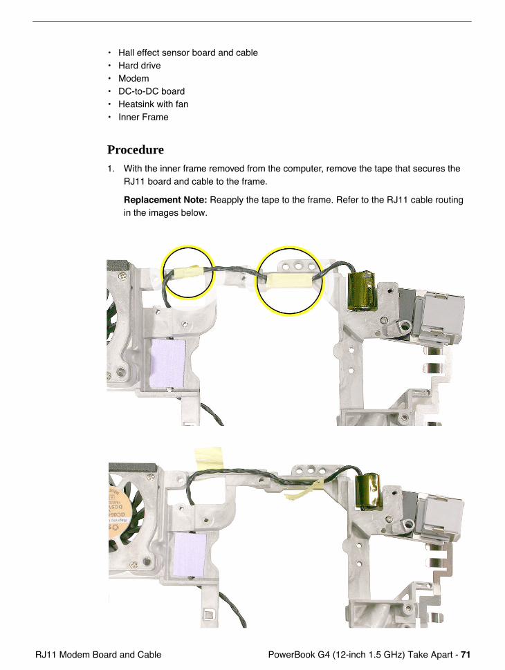
Procedure1. With the inner frame removed from the computer, remove the tape that secures the
RJ11 board and cable to the frame.
Replacement Note: Reapply the tape to the frame. Refer to the RJ11 cable routing in the images below.
72 - PowerBook G4 (12-inch 1.5 GHz) Take Apart RJ11 Modem Board and Cable
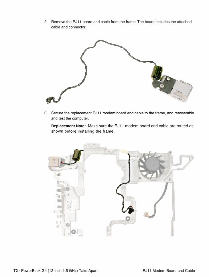
2. Remove the RJ11 board and cable from the frame. The board includes the attached cable and connector.
3. Secure the replacement RJ11 modem board and cable to the frame, and reassemble and test the computer.
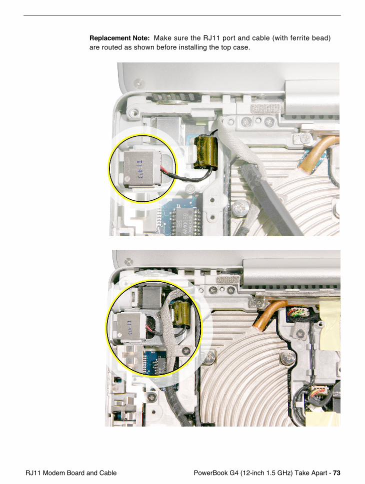
Replacement Note: Make sure the RJ11 modem board and cable are routed as shown before installing the frame.
PowerBook G4 (12-inch 1.5 GHz) Take Apart - 73 RJ11 Modem Board and Cable
Replacement Note: Make sure the RJ11 port and cable (with ferrite bead) are routed as shown before installing the top case.

74 - PowerBook G4 (12-inch 1.5 GHz) Take Apart RJ11 Modem Board and Cable (with Filter Board)
RJ11 Modem Board and Cable (with Filter Board)
Tools
This procedure requires the following tools:• #0 Phillips screwdriver • Black stick (or other nonconductive nylon or plastic flat-blade tool)
Note: To organize the screws you remove from the computer, use a tray with divided compartments (such as a plastic ice cube tray).
Part Location
Preliminary Steps
Before you begin, remove the following:• Battery• Memory door and memory card• Keyboard• Top case• Hall effect sensor board and cable
PowerBook G4 (12-inch 1.5 GHz) Take Apart - 75 RJ11 Modem Board and Cable (with Filter Board)
• Hard drive• Modem• DC-to-DC board• Heatsink with fan• Inner Frame
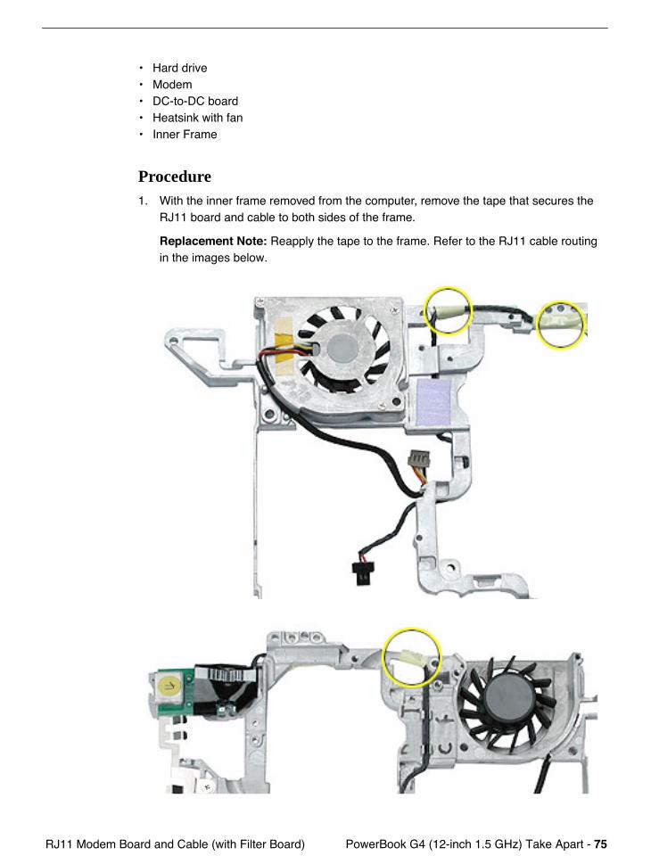
Procedure1. With the inner frame removed from the computer, remove the tape that secures the
RJ11 board and cable to both sides of the frame.
Replacement Note: Reapply the tape to the frame. Refer to the RJ11 cable routing in the images below.
76 - PowerBook G4 (12-inch 1.5 GHz) Take Apart RJ11 Modem Board and Cable (with Filter Board)
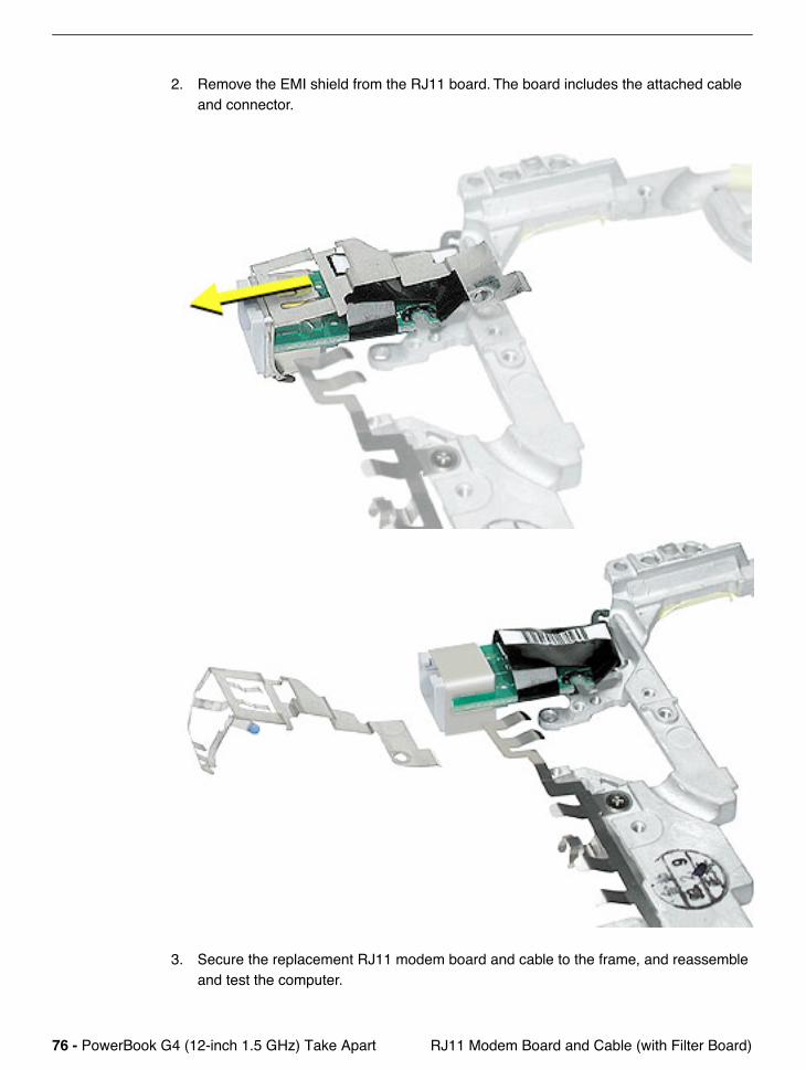
2. Remove the EMI shield from the RJ11 board. The board includes the attached cable and connector.
3. Secure the replacement RJ11 modem board and cable to the frame, and reassemble and test the computer.
PowerBook G4 (12-inch 1.5 GHz) Take Apart - 77 Fan
Fan
Tools
This procedure requires the following tools:• #0 Phillips screwdriver • Black stick (or other nonconductive nylon or plastic flat-blade tool)
Note: To organize the screws you remove from the computer, use a tray with divided compartments (such as a plastic ice cube tray).
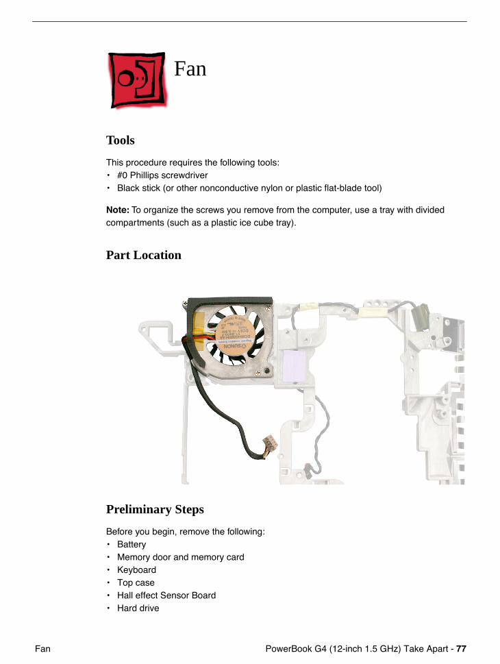
Part Location
Preliminary Steps
Before you begin, remove the following:• Battery• Memory door and memory card• Keyboard• Top case• Hall effect Sensor Board• Hard drive
78 - PowerBook G4 (12-inch 1.5 GHz) Take Apart Fan
• Modem• DC-to-DC board• Heatsink• Inner Frame
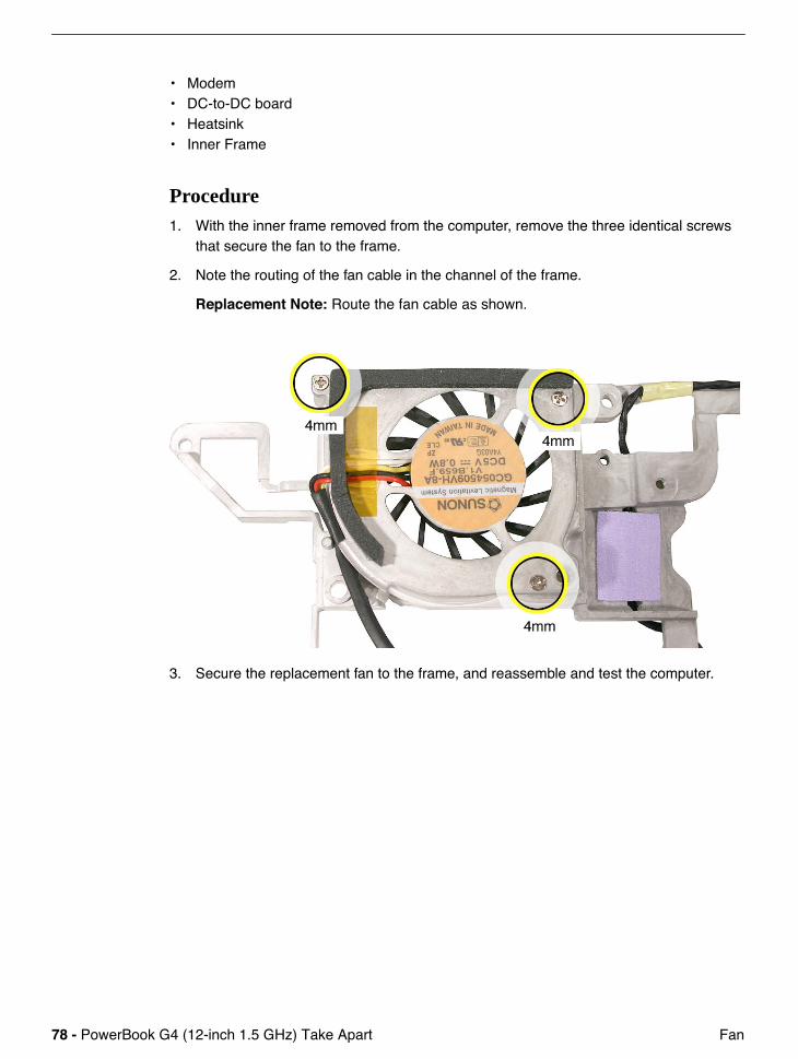
Procedure1. With the inner frame removed from the computer, remove the three identical screws
that secure the fan to the frame.
2. Note the routing of the fan cable in the channel of the frame.
Replacement Note: Route the fan cable as shown.
3. Secure the replacement fan to the frame, and reassemble and test the computer.
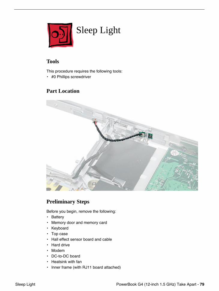
PowerBook G4 (12-inch 1.5 GHz) Take Apart - 79 Sleep Light
Sleep Light
Tools
This procedure requires the following tools:• #0 Phillips screwdriver
Part Location
Preliminary Steps
Before you begin, remove the following:• Battery• Memory door and memory card• Keyboard• Top case• Hall effect sensor board and cable• Hard drive• Modem• DC-to-DC board• Heatsink with fan• Inner frame (with RJ11 board attached)
80 - PowerBook G4 (12-inch 1.5 GHz) Take Apart Sleep Light
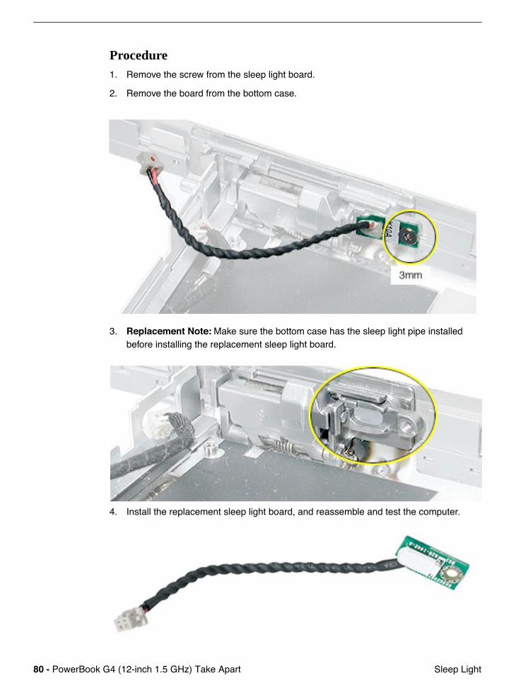
Procedure1. Remove the screw from the sleep light board.
2. Remove the board from the bottom case.
3. Replacement Note: Make sure the bottom case has the sleep light pipe installed before installing the replacement sleep light board.
4. Install the replacement sleep light board, and reassemble and test the computer.
PowerBook G4 (12-inch 1.5 GHz) Take Apart - 81 Logic Board
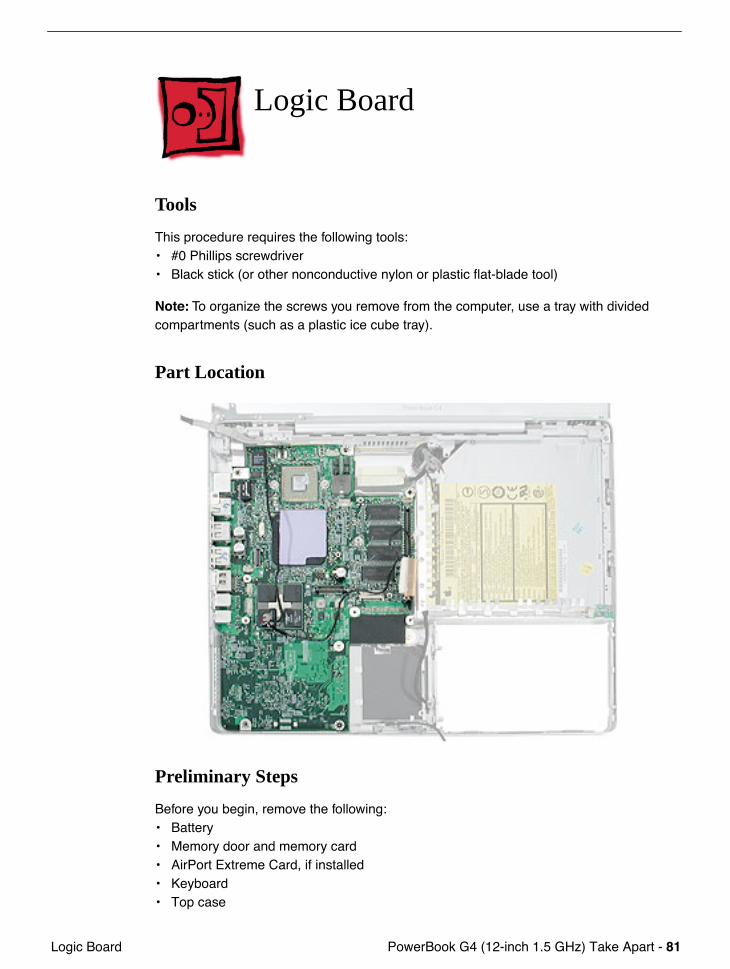
Logic Board
Tools
This procedure requires the following tools:• #0 Phillips screwdriver • Black stick (or other nonconductive nylon or plastic flat-blade tool)
Note: To organize the screws you remove from the computer, use a tray with divided compartments (such as a plastic ice cube tray).
Part Location
Preliminary Steps
Before you begin, remove the following:• Battery• Memory door and memory card• AirPort Extreme Card, if installed• Keyboard• Top case

82 - PowerBook G4 (12-inch 1.5 GHz) Take Apart Logic Board
• Hall effect sensor board and cable• Hard drive• Modem• DC-to-DC board• Heatsink with fan• Inner frame (with RJ11 board attached)
Procedure1. Remove the two screws at the lower right edge of the board.
PowerBook G4 (12-inch 1.5 GHz) Take Apart - 83 Logic Board
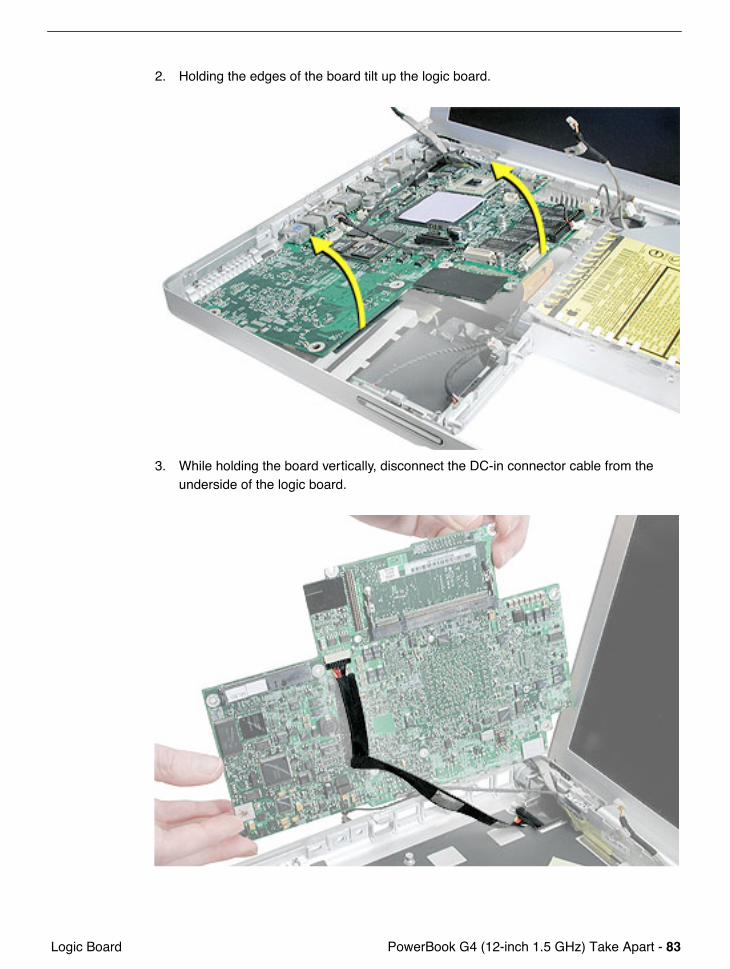
2. Holding the edges of the board tilt up the logic board.
3. While holding the board vertically, disconnect the DC-in connector cable from the underside of the logic board.
84 - PowerBook G4 (12-inch 1.5 GHz) Take Apart Logic Board
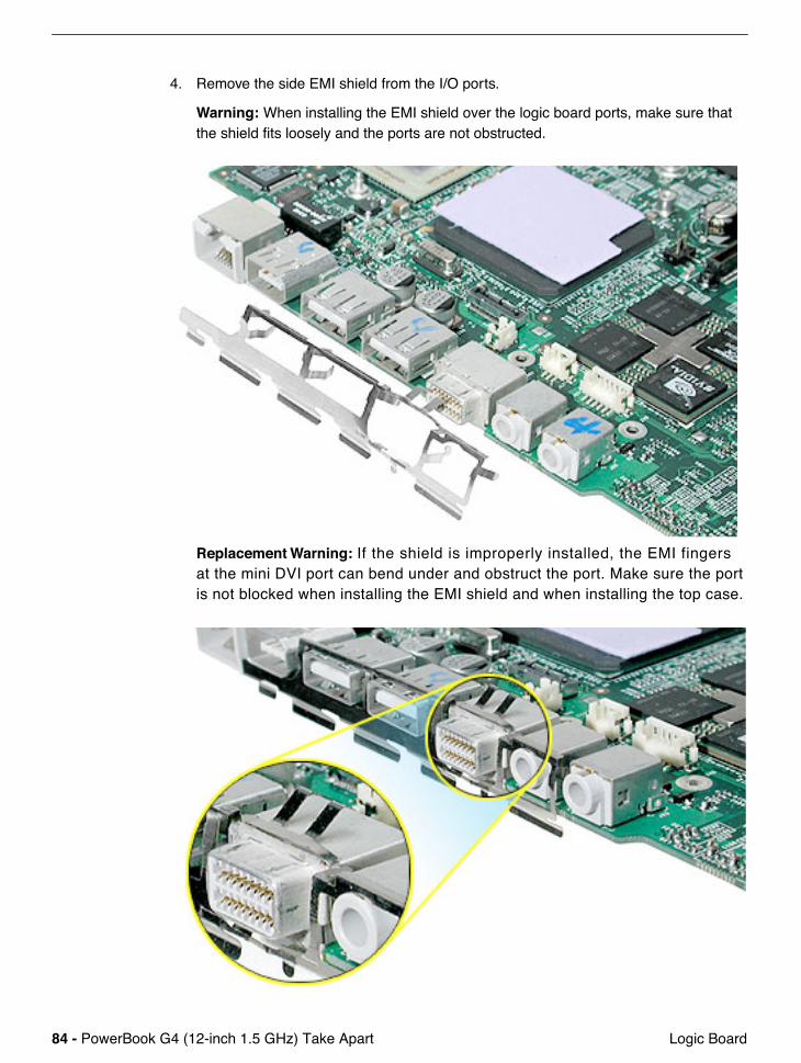
4. Remove the side EMI shield from the I/O ports.
Warning: When installing the EMI shield over the logic board ports, make sure that the shield fits loosely and the ports are not obstructed.
Replacement Warning: If the shield is improperly installed, the EMI fingers at the mini DVI port can bend under and obstruct the port. Make sure the port is not blocked when installing the EMI shield and when installing the top case.
PowerBook G4 (12-inch 1.5 GHz) Take Apart - 85 Logic Board
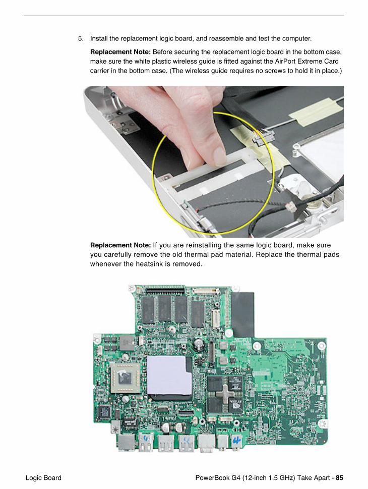
5. Install the replacement logic board, and reassemble and test the computer.
Replacement Note: Before securing the replacement logic board in the bottom case, make sure the white plastic wireless guide is fitted against the AirPort Extreme Card carrier in the bottom case. (The wireless guide requires no screws to hold it in place.)
Replacement Note: If you are reinstalling the same logic board, make sure you carefully remove the old thermal pad material. Replace the thermal pads whenever the heatsink is removed.

86 - PowerBook G4 (12-inch 1.5 GHz) Take Apart DC-In Board
DC-In Board
This procedure requires the following tools:• #0 Phillips screwdriver • Black stick (or other nonconductive nylon or plastic flat-blade tool)
Part Location
Preliminary Steps
Before you begin, remove the following:• Battery• Memory door and memory card• AirPort Extreme Card, if installed• Keyboard• Top case• Hall effect sensor board and cable• Hard drive• Modem• DC-to-DC board
PowerBook G4 (12-inch 1.5 GHz) Take Apart - 87 DC-In Board
• Heatsink with fan• Inner frame (with RJ11 board attached)• Logic board
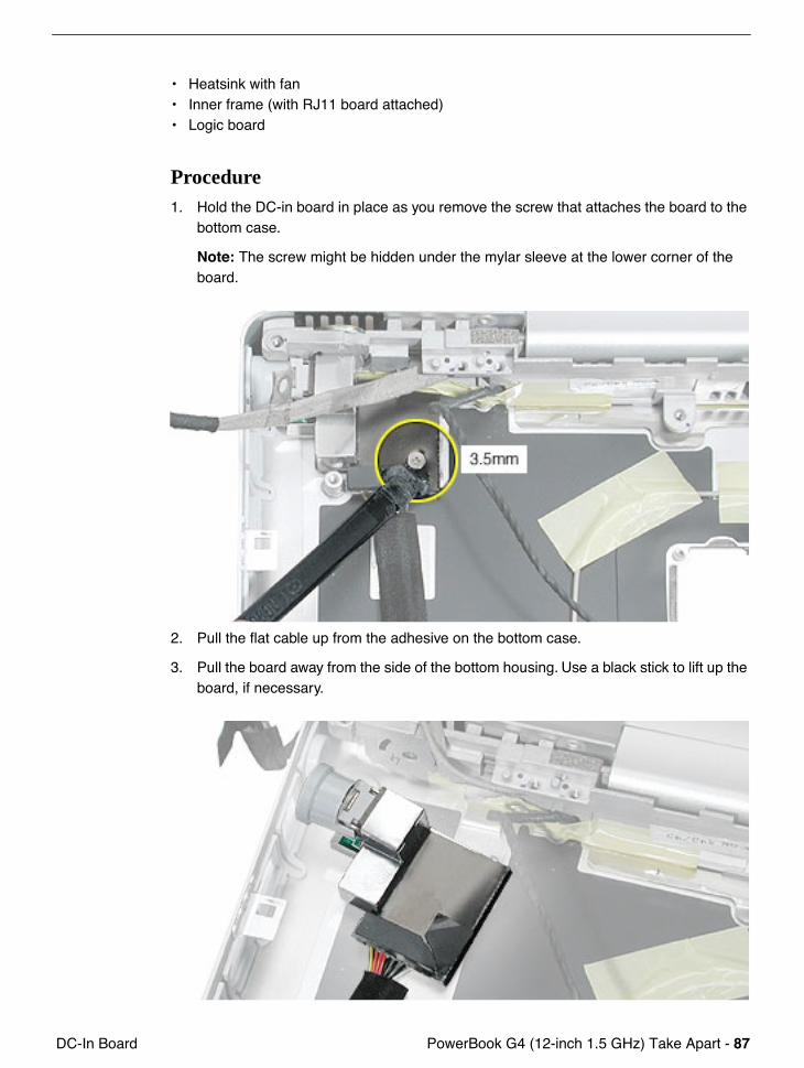
Procedure1. Hold the DC-in board in place as you remove the screw that attaches the board to the
bottom case.
Note: The screw might be hidden under the mylar sleeve at the lower corner of the board.
2. Pull the flat cable up from the adhesive on the bottom case.
3. Pull the board away from the side of the bottom housing. Use a black stick to lift up the board, if necessary.
88 - PowerBook G4 (12-inch 1.5 GHz) Take Apart DC-In Board
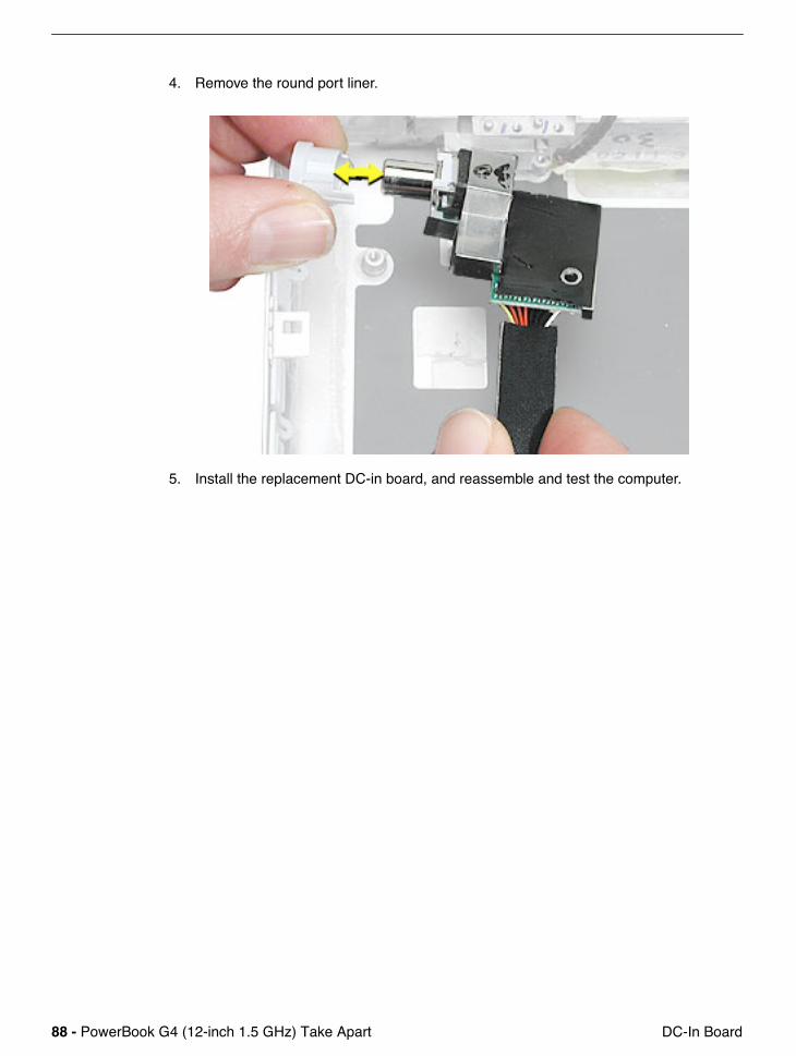
4. Remove the round port liner.
5. Install the replacement DC-in board, and reassemble and test the computer.

PowerBook G4 (12-inch 1.5 GHz) Take Apart - 89 Optical Drive
Optical Drive
Tools
This procedure requires the following tools:• #0 Phillips screwdriver • Black stick (or other nonconductive nylon or plastic flat-blade tool)
Note: To organize the screws you remove from the computer, use a tray with divided compartments (such as a plastic ice cube tray).
Part Location
Preliminary Steps
Before you begin, remove the following:• Battery• Memory door and memory card• AirPort Extreme Card, if installed• Keyboard
90 - PowerBook G4 (12-inch 1.5 GHz) Take Apart Optical Drive
• Top case• Hall effect sensor board and cable• Hard drive• Modem• DC-to-DC board• Heatsink with fan• Inner frame (with RJ11 board attached)• Logic board
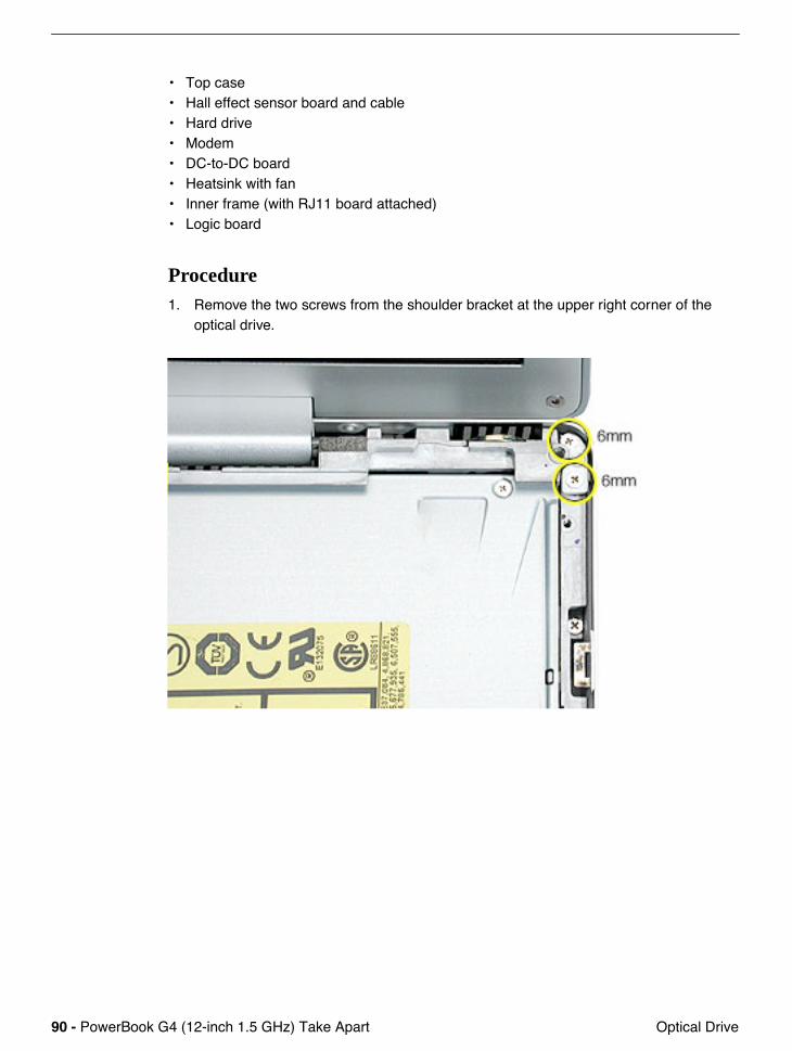
Procedure1. Remove the two screws from the shoulder bracket at the upper right corner of the
optical drive.
PowerBook G4 (12-inch 1.5 GHz) Take Apart - 91 Optical Drive
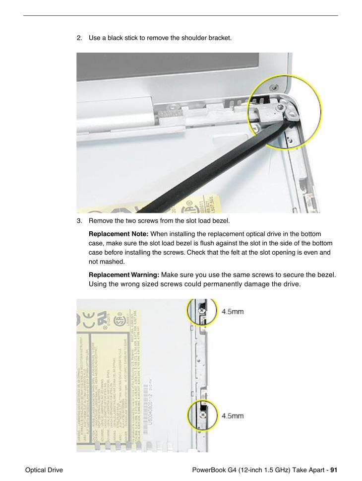
2. Use a black stick to remove the shoulder bracket.
3. Remove the two screws from the slot load bezel.
Replacement Note: When installing the replacement optical drive in the bottom case, make sure the slot load bezel is flush against the slot in the side of the bottom case before installing the screws. Check that the felt at the slot opening is even and not mashed.
Replacement Warning: Make sure you use the same screws to secure the bezel. Using the wrong sized screws could permanently damage the drive.
92 - PowerBook G4 (12-inch 1.5 GHz) Take Apart Optical Drive
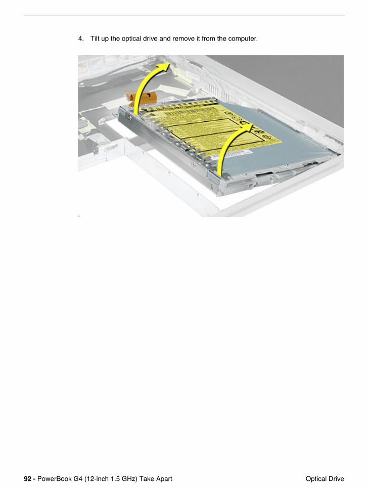
4. Tilt up the optical drive and remove it from the computer.
PowerBook G4 (12-inch 1.5 GHz) Take Apart - 93 Optical Drive
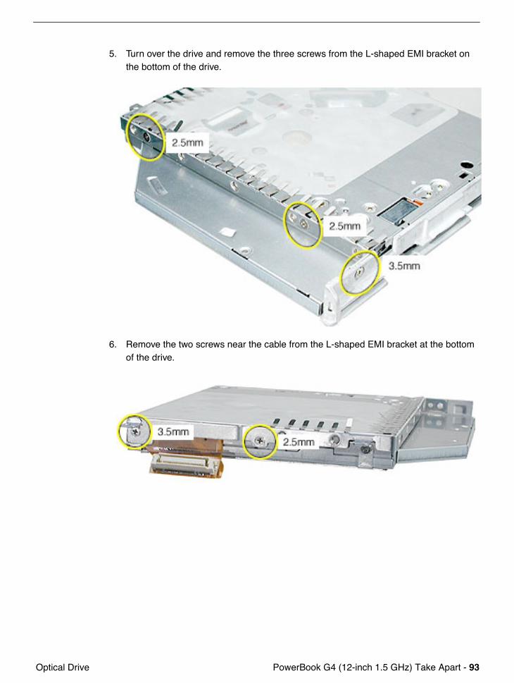
5. Turn over the drive and remove the three screws from the L-shaped EMI bracket on the bottom of the drive.
6. Remove the two screws near the cable from the L-shaped EMI bracket at the bottom of the drive.
94 - PowerBook G4 (12-inch 1.5 GHz) Take Apart Optical Drive
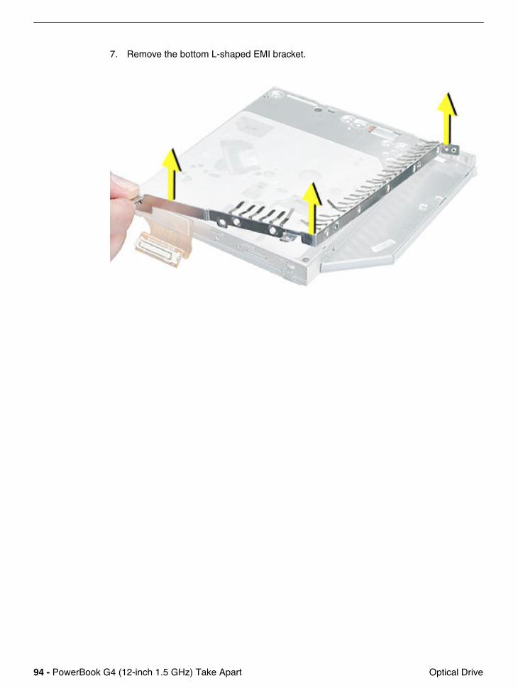
7. Remove the bottom L-shaped EMI bracket.
PowerBook G4 (12-inch 1.5 GHz) Take Apart - 95 Optical Drive
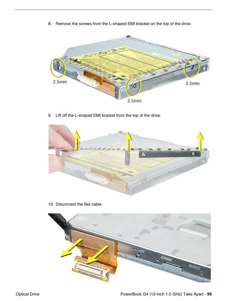
8. Remove the screws from the L-shaped EMI bracket on the top of the drive.
9. Lift off the L-shaped EMI bracket from the top of the drive.
10. Disconnect the flex cable.

96 - PowerBook G4 (12-inch 1.5 GHz) Take Apart Optical Drive
11. Install the replacement optical drive, and reassemble and test the computer.
Note: The optical drive bezel is included with the replacement drive, so do not remove it.
PowerBook G4 (12-inch 1.5 GHz) Take Apart - 97 How to Remove a Stuck Disc from the Slot-Load
How to Remove a Stuck Disc from the Slot-Load Drive
The following instructions explain how to remove a disc that is stuck in the slot-load optical drive.
Important: When a disc becomes stuck in the slot-load optical drive, it makes the drive unusable. Make sure you have a replacement drive available.
Tools
This procedure requires the following tools:• ESD wriststrap and mat• #0 Phillips screwdriver• Black stick (or other nonconductive nylon or plastic tool)
Preliminary Steps
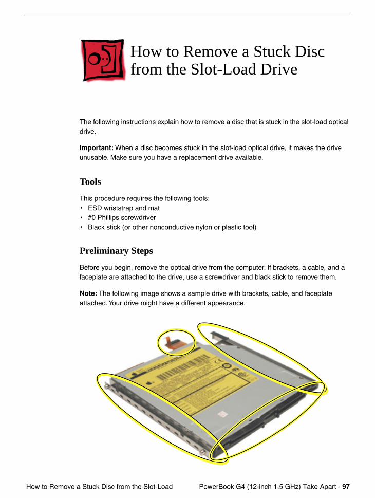
Before you begin, remove the optical drive from the computer. If brackets, a cable, and a faceplate are attached to the drive, use a screwdriver and black stick to remove them.
Note: The following image shows a sample drive with brackets, cable, and faceplate attached. Your drive might have a different appearance.
98 - PowerBook G4 (12-inch 1.5 GHz) Take Apart How to Remove a Stuck Disc from the Slot-Load
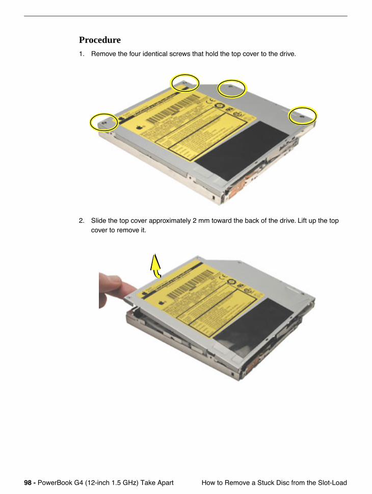
Procedure1. Remove the four identical screws that hold the top cover to the drive.
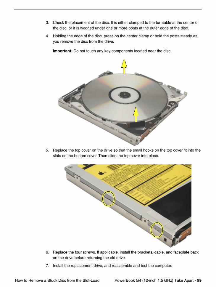
2. Slide the top cover approximately 2 mm toward the back of the drive. Lift up the top cover to remove it.
PowerBook G4 (12-inch 1.5 GHz) Take Apart - 99 How to Remove a Stuck Disc from the Slot-Load
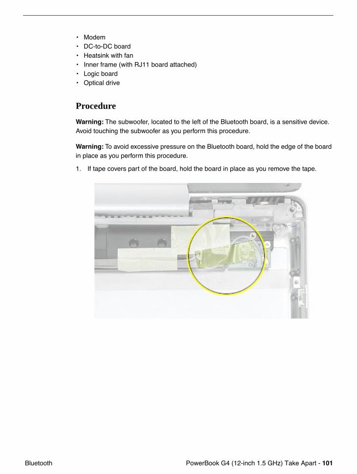
3. Check the placement of the disc. It is either clamped to the turntable at the center of the disc, or it is wedged under one or more posts at the outer edge of the disc.
4. Holding the edge of the disc, press on the center clamp or hold the posts steady as you remove the disc from the drive.
Important: Do not touch any key components located near the disc.
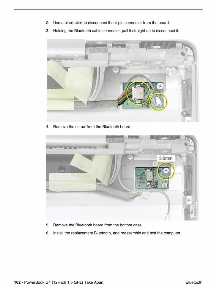
5. Replace the top cover on the drive so that the small hooks on the top cover fit into the slots on the bottom cover. Then slide the top cover into place.
6. Replace the four screws. If applicable, install the brackets, cable, and faceplate back on the drive before returning the old drive.
7. Install the replacement drive, and reassemble and test the computer.

100 - PowerBook G4 (12-inch 1.5 GHz) Take Apart Bluetooth
Bluetooth
Tools
This procedure requires the following tools:• #0 Phillips screwdriver • Black stick (or other nonconductive nylon or plastic flat-blade tool)
Part Location
Preliminary Steps
Before you begin, remove the following:• Battery• Memory door and memory card• AirPort Extreme Card, if installed• Keyboard• Top case• Hall effect sensor board and cable• Hard drive
PowerBook G4 (12-inch 1.5 GHz) Take Apart - 101 Bluetooth
• Modem• DC-to-DC board• Heatsink with fan• Inner frame (with RJ11 board attached)• Logic board• Optical drive
Procedure
Warning: The subwoofer, located to the left of the Bluetooth board, is a sensitive device. Avoid touching the subwoofer as you perform this procedure.
Warning: To avoid excessive pressure on the Bluetooth board, hold the edge of the board in place as you perform this procedure.
1. If tape covers part of the board, hold the board in place as you remove the tape.
102 - PowerBook G4 (12-inch 1.5 GHz) Take Apart Bluetooth
2. Use a black stick to disconnect the 4-pin connector from the board.
3. Holding the Bluetooth cable connector, pull it straight up to disconnect it.
4. Remove the screw from the Bluetooth board.
5. Remove the Bluetooth board from the bottom case.
6. Install the replacement Bluetooth, and reassemble and test the computer.
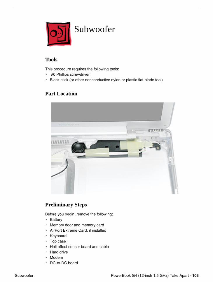
PowerBook G4 (12-inch 1.5 GHz) Take Apart - 103 Subwoofer
Subwoofer
Tools
This procedure requires the following tools:• #0 Phillips screwdriver• Black stick (or other nonconductive nylon or plastic flat-blade tool)
Part Location
Preliminary Steps
Before you begin, remove the following:• Battery• Memory door and memory card• AirPort Extreme Card, if installed• Keyboard• Top case• Hall effect sensor board and cable• Hard drive• Modem• DC-to-DC board
104 - PowerBook G4 (12-inch 1.5 GHz) Take Apart Subwoofer
• Heatsink with fan• Inner frame (with RJ11 board attached)• Logic board• Optical drive• Bluetooth
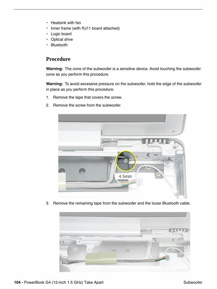
Procedure
Warning: The cone of the subwoofer is a sensitive device. Avoid touching the subwoofer cone as you perform this procedure.
Warning: To avoid excessive pressure on the subwoofer, hold the edge of the subwoofer in place as you perform this procedure.
1. Remove the tape that covers the screw.
2. Remove the screw from the subwoofer.
3. Remove the remaining tape from the subwoofer and the loose Bluetooth cable.
PowerBook G4 (12-inch 1.5 GHz) Take Apart - 105 Subwoofer
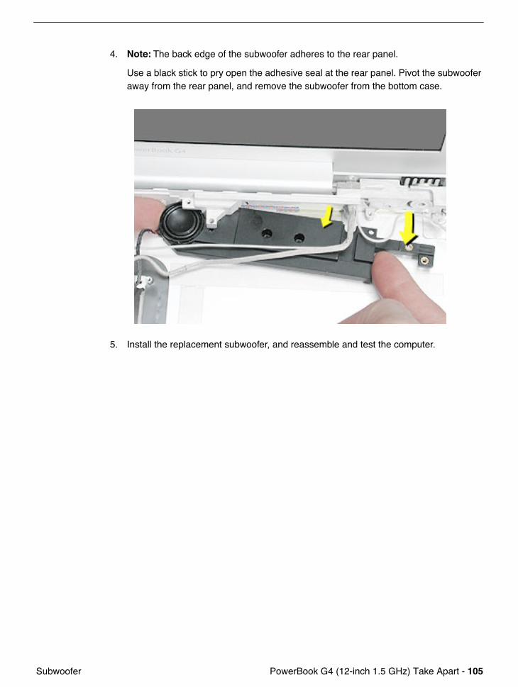
4. Note: The back edge of the subwoofer adheres to the rear panel.
Use a black stick to pry open the adhesive seal at the rear panel. Pivot the subwoofer away from the rear panel, and remove the subwoofer from the bottom case.
5. Install the replacement subwoofer, and reassemble and test the computer.
106 - PowerBook G4 (12-inch 1.5 GHz) Take Apart Display Module
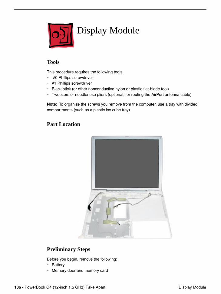
Display Module
Tools
This procedure requires the following tools:• #0 Phillips screwdriver• #1 Phillips screwdriver• Black stick (or other nonconductive nylon or plastic flat-blade tool)• Tweezers or needlenose pliers (optional; for routing the AirPort antenna cable)
Note: To organize the screws you remove from the computer, use a tray with divided compartments (such as a plastic ice cube tray).
Part Location
Preliminary Steps
Before you begin, remove the following:• Battery• Memory door and memory card
PowerBook G4 (12-inch 1.5 GHz) Take Apart - 107 Display Module
• AirPort Extreme Card, if installed• Keyboard• Top case• Hall effect sensor board and cable• Hard drive• Modem• DC-to-DC board• Heatsink with fan• Inner frame (with RJ11 board attached)• Logic board• DC-in board• Optical drive• Bluetooth• Subwoofer
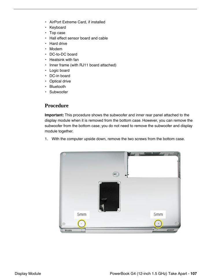
Procedure
Important: This procedure shows the subwoofer and inner rear panel attached to the display module when it is removed from the bottom case. However, you can remove the subwoofer from the bottom case; you do not need to remove the subwoofer and display module together.
1. With the computer upside down, remove the two screws from the bottom case.
108 - PowerBook G4 (12-inch 1.5 GHz) Take Apart Display Module
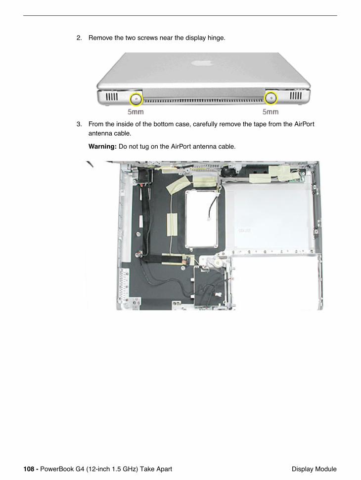
2. Remove the two screws near the display hinge.
3. From the inside of the bottom case, carefully remove the tape from the AirPort antenna cable.
Warning: Do not tug on the AirPort antenna cable.
PowerBook G4 (12-inch 1.5 GHz) Take Apart - 109 Display Module
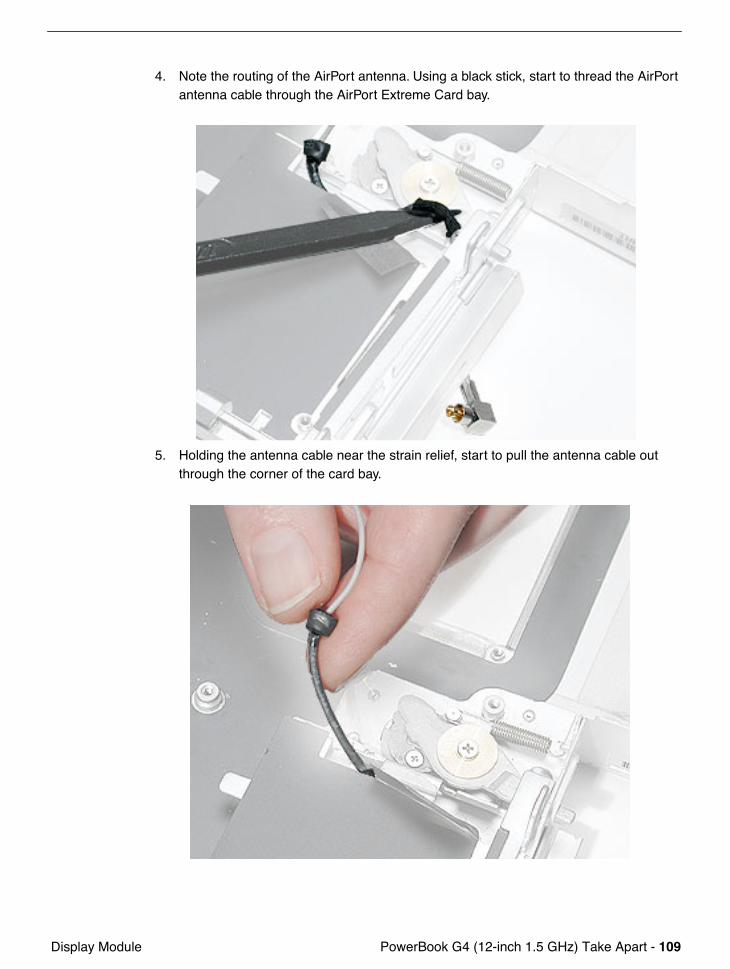
4. Note the routing of the AirPort antenna. Using a black stick, start to thread the AirPort antenna cable through the AirPort Extreme Card bay.
5. Holding the antenna cable near the strain relief, start to pull the antenna cable out through the corner of the card bay.
110 - PowerBook G4 (12-inch 1.5 GHz) Take Apart Display Module
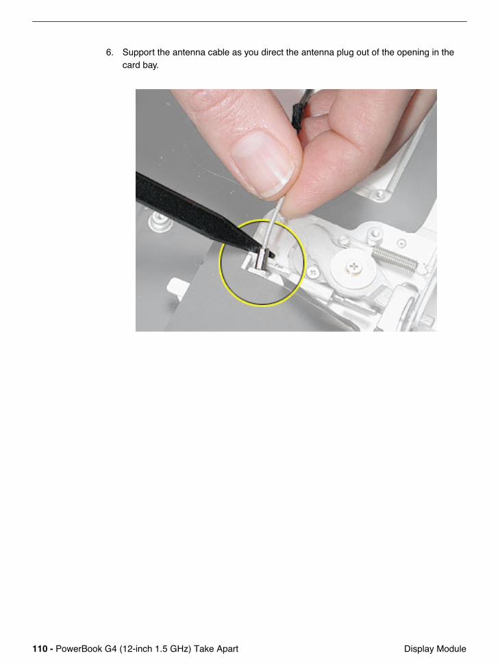
6. Support the antenna cable as you direct the antenna plug out of the opening in the card bay.
PowerBook G4 (12-inch 1.5 GHz) Take Apart - 111 Display Module
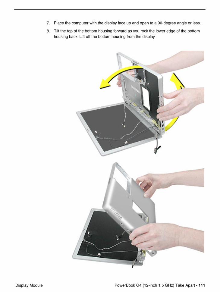
7. Place the computer with the display face up and open to a 90-degree angle or less.
8. Tilt the top of the bottom housing forward as you rock the lower edge of the bottom housing back. Lift off the bottom housing from the display.

112 - PowerBook G4 (12-inch 1.5 GHz) Take Apart Display Module
Important: The display might get caught on the hooks (shown below) on the bottom case. If so, gently twist the bottom case to release it from the display. When reinstalling the display, align the slots to the hooks.
PowerBook G4 (12-inch 1.5 GHz) Take Apart - 113 Display Module
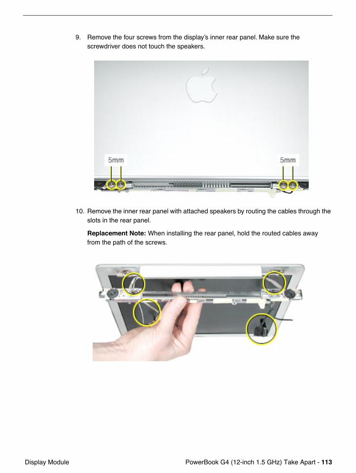
9. Remove the four screws from the display’s inner rear panel. Make sure the screwdriver does not touch the speakers.
10. Remove the inner rear panel with attached speakers by routing the cables through the slots in the rear panel.
Replacement Note: When installing the rear panel, hold the routed cables away from the path of the screws.
114 - PowerBook G4 (12-inch 1.5 GHz) Take Apart Display Module
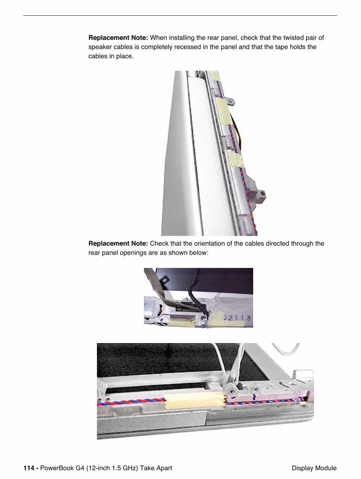
Replacement Note: When installing the rear panel, check that the twisted pair of speaker cables is completely recessed in the panel and that the tape holds the cables in place.
Replacement Note: Check that the orientation of the cables directed through the rear panel openings are as shown below:
PowerBook G4 (12-inch 1.5 GHz) Take Apart - 115 Display Module
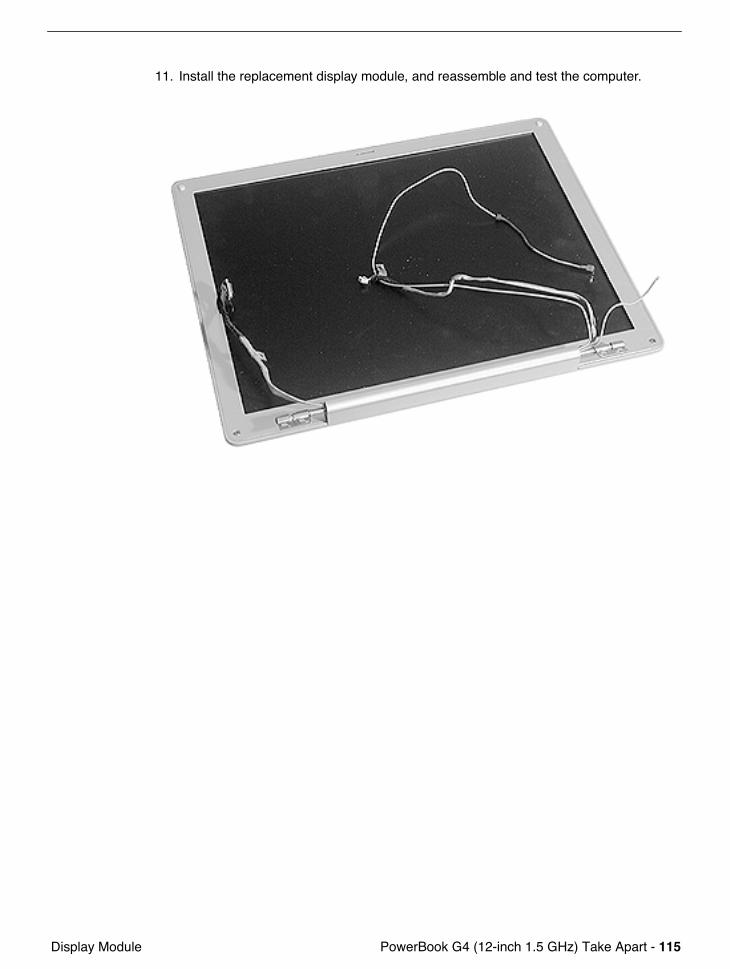
11. Install the replacement display module, and reassemble and test the computer.
116 - PowerBook G4 (12-inch 1.5 GHz) Take Apart Bottom Case
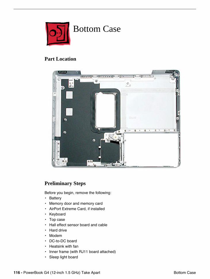
Bottom Case
Part Location
Preliminary Steps
Before you begin, remove the following:• Battery• Memory door and memory card• AirPort Extreme Card, if installed• Keyboard• Top case• Hall effect sensor board and cable• Hard drive• Modem• DC-to-DC board• Heatsink with fan• Inner frame (with RJ11 board attached)• Sleep light board
PowerBook G4 (12-inch 1.5 GHz) Take Apart - 117 Bottom Case
• Logic board• DC-in board• Optical drive• Bluetooth• Subwoofer• Display module
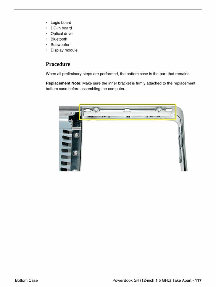
Procedure
When all preliminary steps are performed, the bottom case is the part that remains.
Replacement Note: Make sure the inner bracket is firmly attached to the replacement bottom case before assembling the computer.
118 - PowerBook G4 (12-inch 1.5 GHz) Take Apart Display Housing
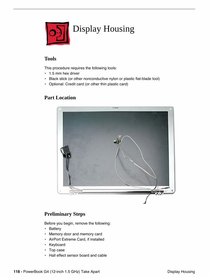
Display Housing
Tools
This procedure requires the following tools:• 1.5 mm hex driver• Black stick (or other nonconductive nylon or plastic flat-blade tool) • Optional: Credit card (or other thin plastic card)
Part Location
Preliminary Steps
Before you begin, remove the following:• Battery• Memory door and memory card• AirPort Extreme Card, if installed• Keyboard• Top case• Hall effect sensor board and cable
PowerBook G4 (12-inch 1.5 GHz) Take Apart - 119 Display Housing
• Hard drive• Modem• DC-to-DC board• Heatsink with fan• Inner frame (with RJ11 board attached)• Logic board• DC-in board• Optical drive• Display module
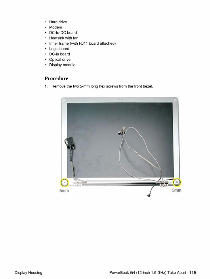
Procedure1. Remove the two 5-mm long hex screws from the front bezel.
120 - PowerBook G4 (12-inch 1.5 GHz) Take Apart Display Housing
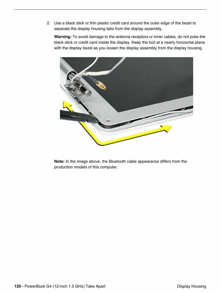
2. Use a black stick or thin plastic credit card around the outer edge of the bezel to separate the display housing tabs from the display assembly.
Warning: To avoid damage to the antenna receptors or inner cables, do not poke the black stick or credit card inside the display. Keep the tool at a nearly horizontal plane with the display bezel as you loosen the display assembly from the display housing.
Note: In the image above, the Bluetooth cable appearance differs from the production models of this computer.
PowerBook G4 (12-inch 1.5 GHz) Take Apart - 121 Display Housing
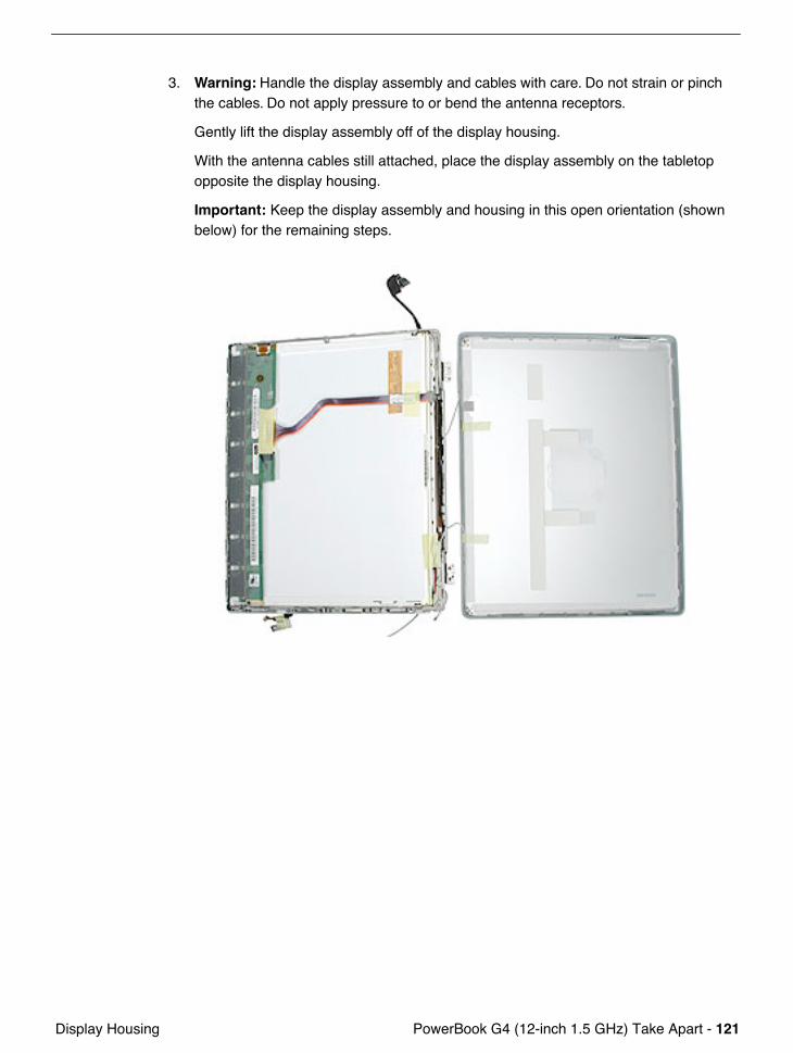
3. Warning: Handle the display assembly and cables with care. Do not strain or pinch the cables. Do not apply pressure to or bend the antenna receptors.
Gently lift the display assembly off of the display housing.
With the antenna cables still attached, place the display assembly on the tabletop opposite the display housing.
Important: Keep the display assembly and housing in this open orientation (shown below) for the remaining steps.
122 - PowerBook G4 (12-inch 1.5 GHz) Take Apart Display Housing
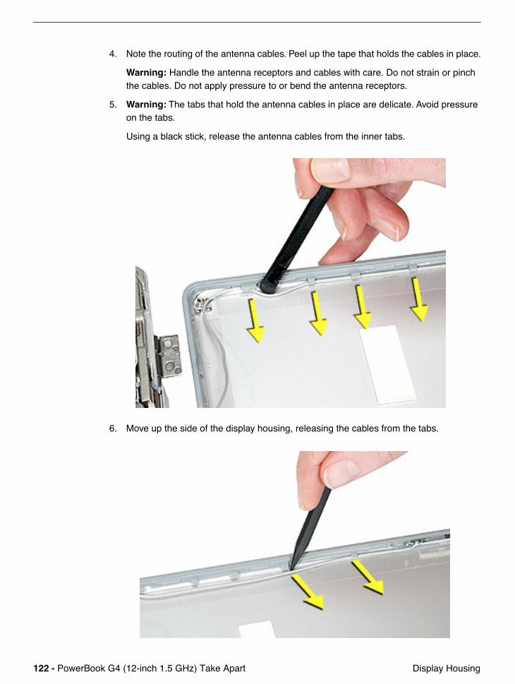
4. Note the routing of the antenna cables. Peel up the tape that holds the cables in place.
Warning: Handle the antenna receptors and cables with care. Do not strain or pinch the cables. Do not apply pressure to or bend the antenna receptors.
5. Warning: The tabs that hold the antenna cables in place are delicate. Avoid pressure on the tabs.
Using a black stick, release the antenna cables from the inner tabs.
6. Move up the side of the display housing, releasing the cables from the tabs.
PowerBook G4 (12-inch 1.5 GHz) Take Apart - 123 Display Housing
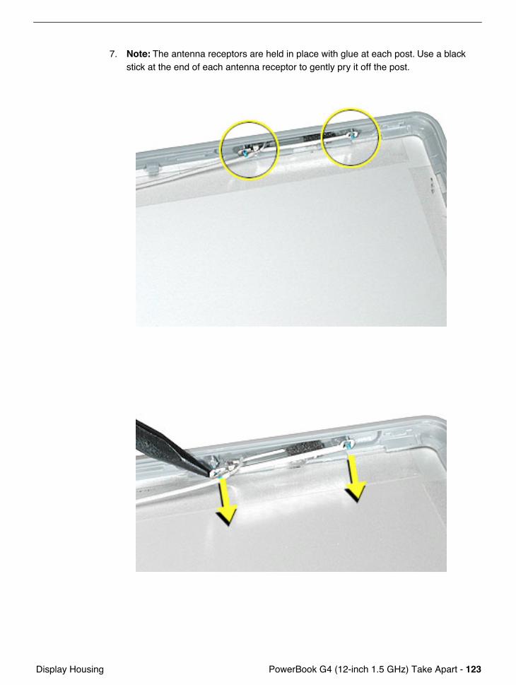
7. Note: The antenna receptors are held in place with glue at each post. Use a black stick at the end of each antenna receptor to gently pry it off the post.
124 - PowerBook G4 (12-inch 1.5 GHz) Take Apart Display Housing
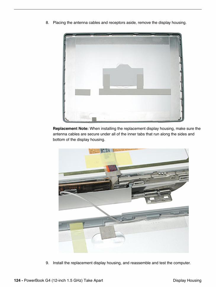
8. Placing the antenna cables and receptors aside, remove the display housing.
Replacement Note: When installing the replacement display housing, make sure the antenna cables are secure under all of the inner tabs that run along the sides and bottom of the display housing.
9. Install the replacement display housing, and reassemble and test the computer.
PowerBook G4 (12-inch 1.5 GHz) Take Apart - 125 LCD Panel
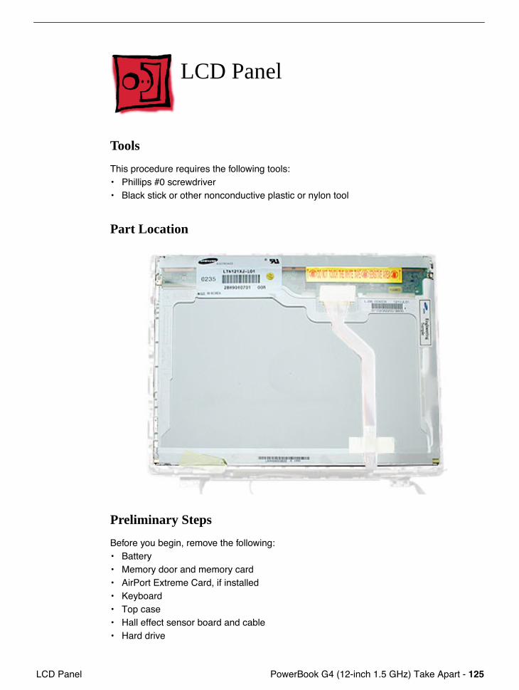
LCD Panel
Tools
This procedure requires the following tools:• Phillips #0 screwdriver• Black stick or other nonconductive plastic or nylon tool
Part Location
Preliminary Steps
Before you begin, remove the following:• Battery• Memory door and memory card• AirPort Extreme Card, if installed• Keyboard• Top case• Hall effect sensor board and cable• Hard drive
126 - PowerBook G4 (12-inch 1.5 GHz) Take Apart LCD Panel
• Modem• DC-to-DC board• Heatsink with fan• Inner frame (with RJ11 board attached)• Logic board• DC-in board• Optical drive• Display module• Display housing
Procedure
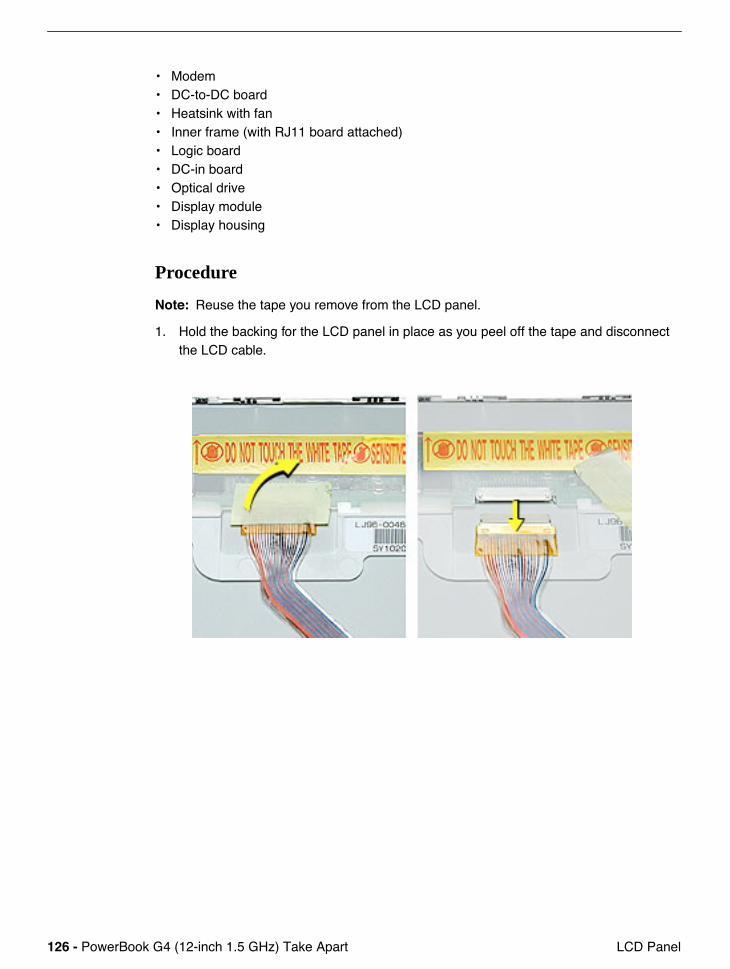
Note: Reuse the tape you remove from the LCD panel.
1. Hold the backing for the LCD panel in place as you peel off the tape and disconnect the LCD cable.
PowerBook G4 (12-inch 1.5 GHz) Take Apart - 127 LCD Panel
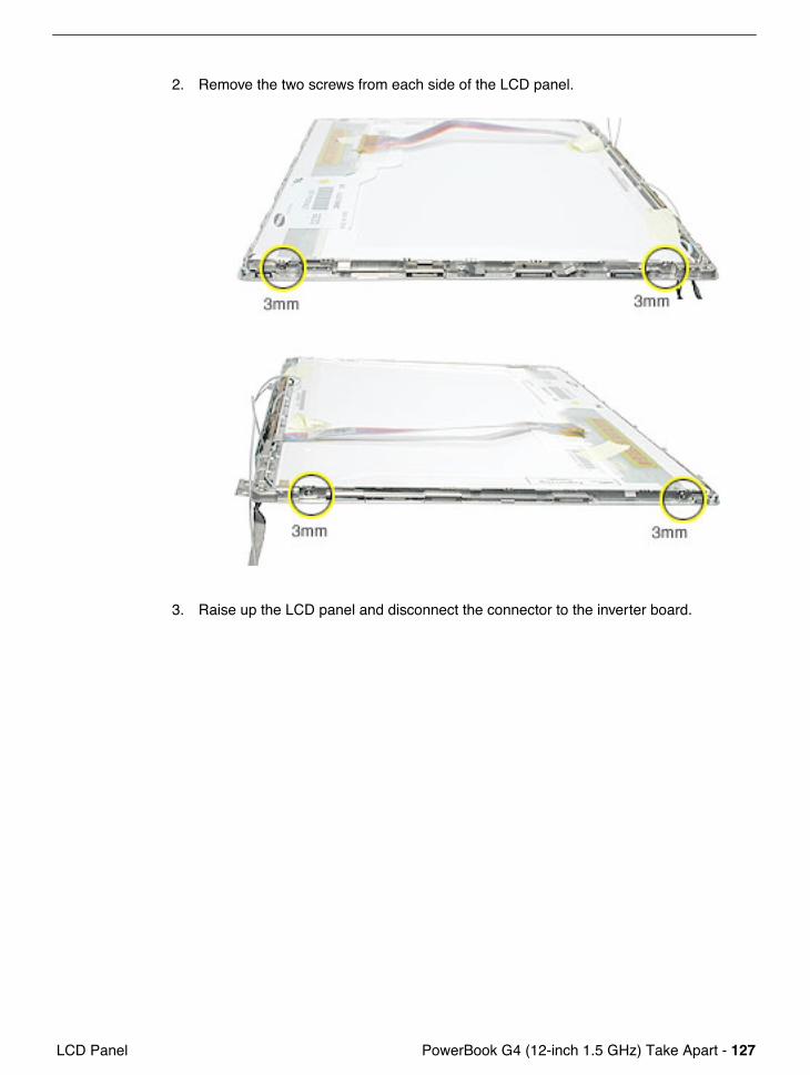
2. Remove the two screws from each side of the LCD panel.
3. Raise up the LCD panel and disconnect the connector to the inverter board.
128 - PowerBook G4 (12-inch 1.5 GHz) Take Apart LCD Panel
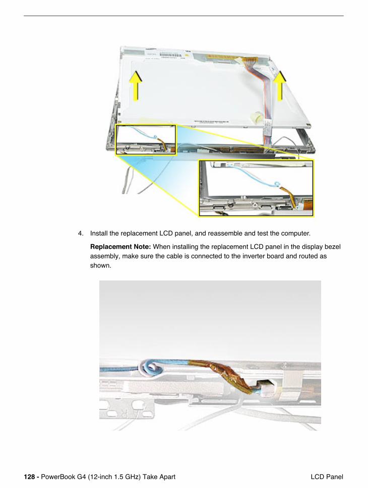
4. Install the replacement LCD panel, and reassemble and test the computer.
Replacement Note: When installing the replacement LCD panel in the display bezel assembly, make sure the cable is connected to the inverter board and routed as shown.
PowerBook G4 (12-inch 1.5 GHz) Take Apart - 129 Inverter Board (and Antenna Cable Assembly)
Inverter Board (and Antenna Cable Assembly)
Tools
This procedure requires the following tools:• Phillips #0 screwdriver• Black stick or other nonconductive plastic or nylon tool
Note: To organize the screws you remove from the computer, use a tray with divided compartments (such as a plastic ice cube tray).
Part Location
Preliminary Steps
Before you begin, remove the following:• Battery• Memory door and memory card• AirPort Extreme Card, if installed• Keyboard• Top case• Hall effect sensor board and cable
130 - PowerBook G4 (12-inch 1.5 GHz) Take Apart Inverter Board (and Antenna Cable Assembly)
• Hard drive• Modem• DC-to-DC board• Heatsink with fan• Inner frame (with RJ11 board attached)• Logic board• DC-in board• Optical drive• Display module• Display housing• LCD panel
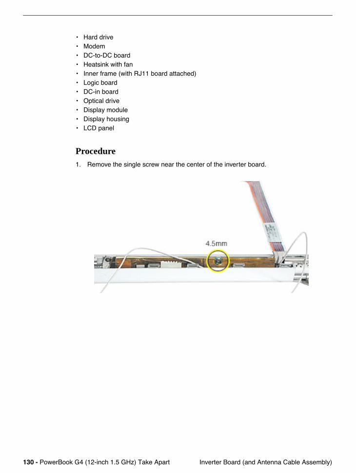
Procedure1. Remove the single screw near the center of the inverter board.
PowerBook G4 (12-inch 1.5 GHz) Take Apart - 131 Inverter Board (and Antenna Cable Assembly)
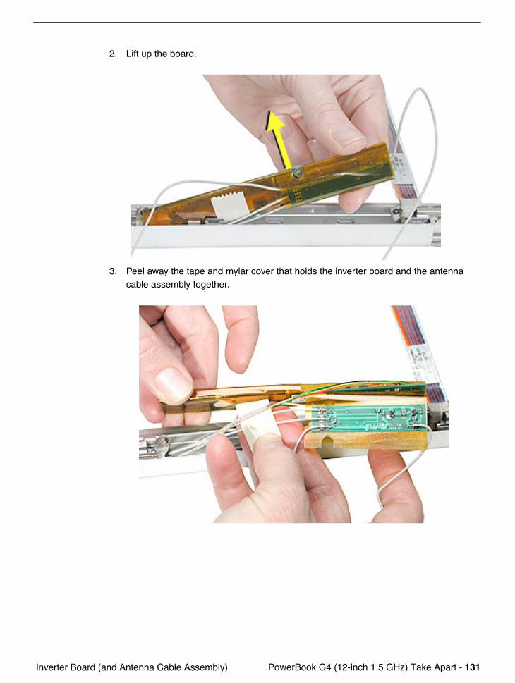
2. Lift up the board.
3. Peel away the tape and mylar cover that holds the inverter board and the antenna cable assembly together.
132 - PowerBook G4 (12-inch 1.5 GHz) Take Apart Inverter Board (and Antenna Cable Assembly)
4. Separate the antenna cable assembly (board with attached antenna cables and Bluetooth cable) from the inverter board.
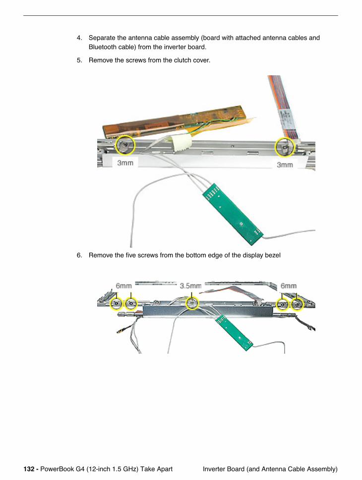
5. Remove the screws from the clutch cover.
6. Remove the five screws from the bottom edge of the display bezel
PowerBook G4 (12-inch 1.5 GHz) Take Apart - 133 Inverter Board (and Antenna Cable Assembly)
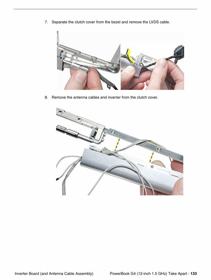
7. Separate the clutch cover from the bezel and remove the LVDS cable.
8. Remove the antenna cables and inverter from the clutch cover.
134 - PowerBook G4 (12-inch 1.5 GHz) Take Apart Inverter Board (and Antenna Cable Assembly)
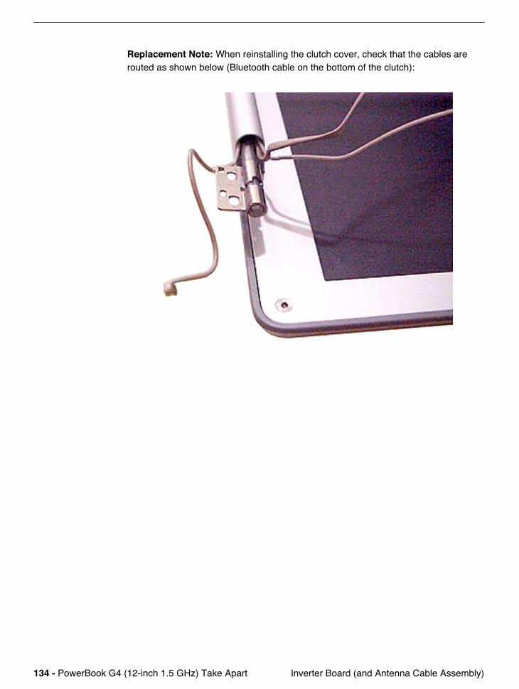
Replacement Note: When reinstalling the clutch cover, check that the cables are routed as shown below (Bluetooth cable on the bottom of the clutch):
PowerBook G4 (12-inch 1.5 GHz) Take Apart - 135 Hinges with Bezel Brace
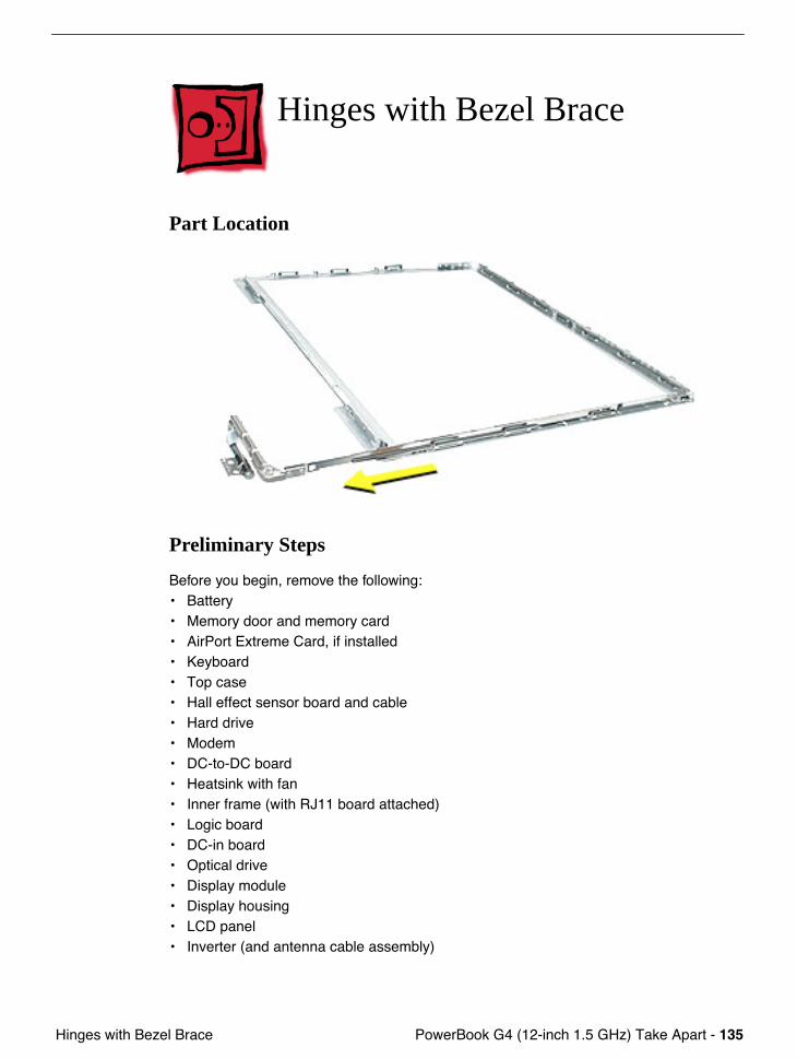
Hinges with Bezel Brace
Part Location
Preliminary Steps
Before you begin, remove the following:• Battery• Memory door and memory card• AirPort Extreme Card, if installed• Keyboard• Top case• Hall effect sensor board and cable• Hard drive• Modem• DC-to-DC board• Heatsink with fan• Inner frame (with RJ11 board attached)• Logic board• DC-in board• Optical drive• Display module• Display housing• LCD panel• Inverter (and antenna cable assembly)
136 - PowerBook G4 (12-inch 1.5 GHz) Take Apart Hinges with Bezel Brace
Procedure
Important: In the following steps, note that because of the position of the bezel, the designation of right and left differs. For example, the right hinge with bezel brace is removed from the left side of the bezel because you are viewing the bezel from its inner side. Likewise, the left hinge with bezel brace is removed from the right side of the bezel.
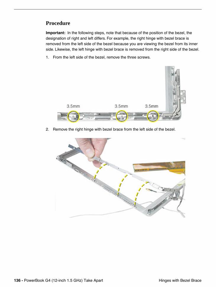
1. From the left side of the bezel, remove the three screws.
2. Remove the right hinge with bezel brace from the left side of the bezel.
PowerBook G4 (12-inch 1.5 GHz) Take Apart - 137 Hinges with Bezel Brace
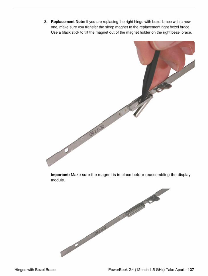
3. Replacement Note: If you are replacing the right hinge with bezel brace with a new one, make sure you transfer the sleep magnet to the replacement right bezel brace. Use a black stick to tilt the magnet out of the magnet holder on the right bezel brace.
Important: Make sure the magnet is in place before reassembling the display module.
138 - PowerBook G4 (12-inch 1.5 GHz) Take Apart Hinges with Bezel Brace
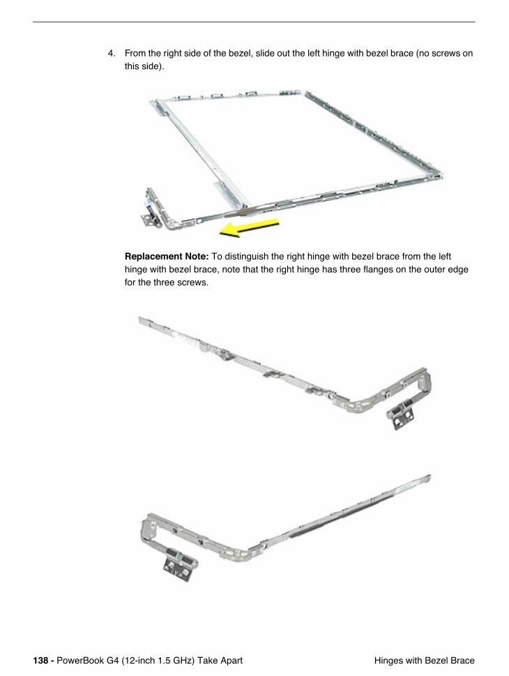
4. From the right side of the bezel, slide out the left hinge with bezel brace (no screws on this side).
Replacement Note: To distinguish the right hinge with bezel brace from the left hinge with bezel brace, note that the right hinge has three flanges on the outer edge for the three screws.
PowerBook G4 (12-inch 1.5 GHz) Take Apart - 139 Hinges with Bezel Brace
Identifying the Replacement Hinges
Before ordering a replacement hinge with bezel brace, verify the LCD panel manufacturer and hinge marking, as follows.
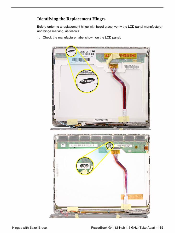
1. Check the manufacturer label shown on the LCD panel.
140 - PowerBook G4 (12-inch 1.5 GHz) Take Apart Hinges with Bezel Brace
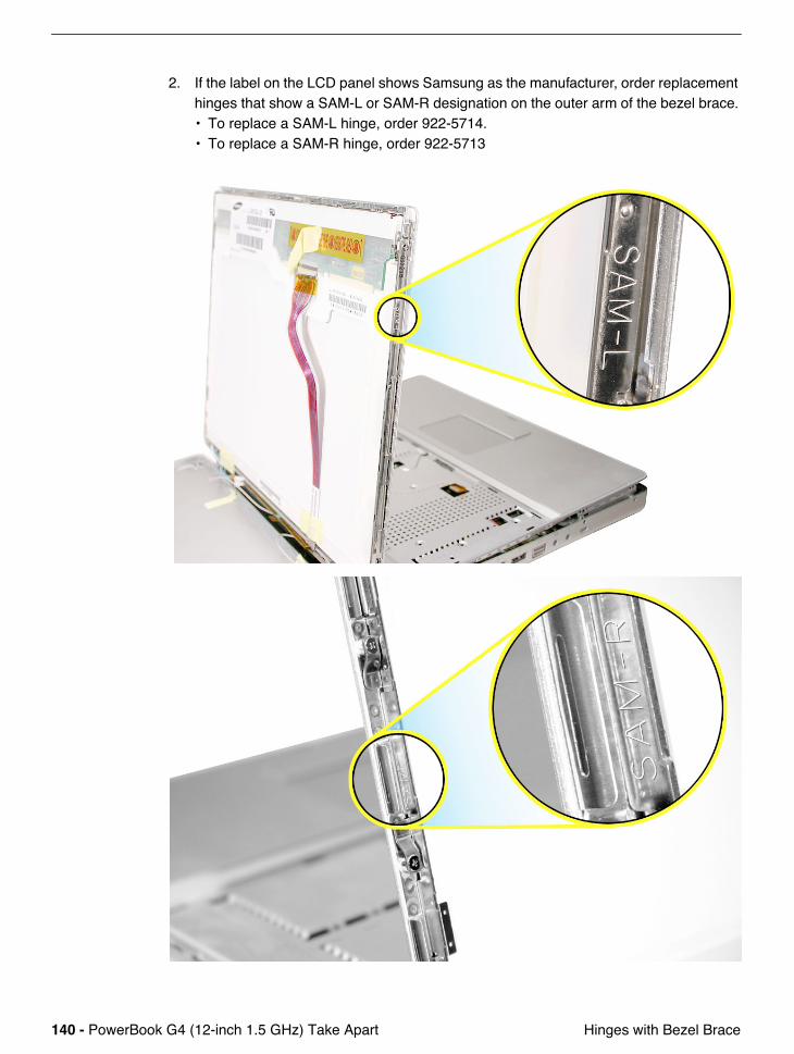
2. If the label on the LCD panel shows Samsung as the manufacturer, order replacement hinges that show a SAM-L or SAM-R designation on the outer arm of the bezel brace. • To replace a SAM-L hinge, order 922-5714.• To replace a SAM-R hinge, order 922-5713
PowerBook G4 (12-inch 1.5 GHz) Take Apart - 141 Hinges with Bezel Brace
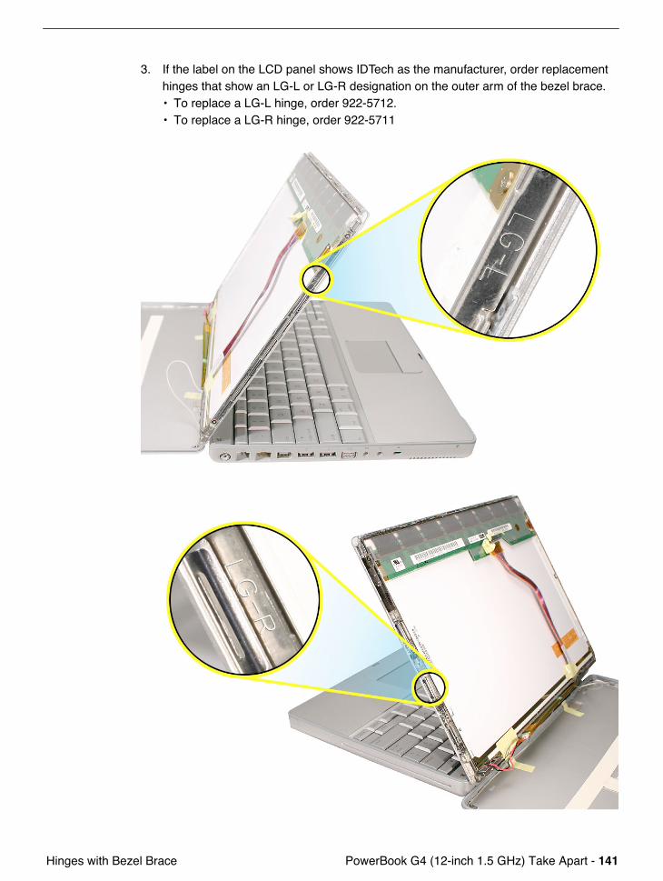
3. If the label on the LCD panel shows IDTech as the manufacturer, order replacement hinges that show an LG-L or LG-R designation on the outer arm of the bezel brace. • To replace a LG-L hinge, order 922-5712.• To replace a LG-R hinge, order 922-5711
142 - PowerBook G4 (12-inch 1.5 GHz) Take Apart Display Bezel
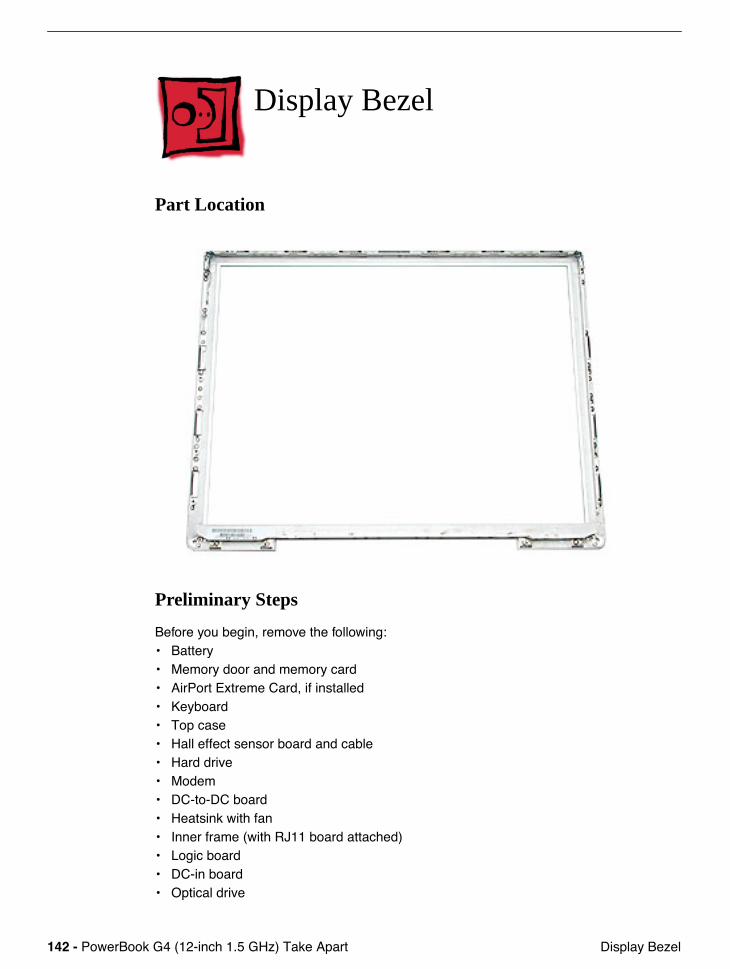
Display Bezel
Part Location
Preliminary Steps
Before you begin, remove the following:• Battery• Memory door and memory card• AirPort Extreme Card, if installed• Keyboard• Top case• Hall effect sensor board and cable• Hard drive• Modem• DC-to-DC board• Heatsink with fan• Inner frame (with RJ11 board attached)• Logic board• DC-in board• Optical drive
PowerBook G4 (12-inch 1.5 GHz) Take Apart - 143 Display Bezel
• Display module• Display housing• LCD panel• Inverter (and antenna cable assembly)
Procedure
When all preliminary steps are performed, the display bezel is the part that remains.

© 2005 Apple Computer, Inc. All rights reserved.
Service Source
Troubleshooting
PowerBook G4 (12-inch 1.5 GHz)

PowerBook G4 (12" 1.5 GHz) Troubleshooting -
1
Symptom Charts
Symptom Charts
How to Use the Symptom Charts
The Symptom Charts included in this chapter will help you diagnose specific symptoms related to the product.
The steps to solve a symptom are listed sequentially. You might not need to perform every step before the symptom is solved. Start with the first step, and then test for the symptom. If the symptom persists, replace any modules you removed, go to the next step, and test again. Continue down the list until the symptom is solved.
Important:
This computer starts up only in Mac OS X. Mac OS 9 is not available as a startup disk and previous versions of the Mac OS should not be installed on this computer.
2 -
PowerBook G4 (12" 1.5 GHz) Troubleshooting AirPort Extreme Card Symptom Charts
AirPort Extreme Card
AirPort Extreme Card not recognized
1. Use Software Update in Mac OS X system preferences or see the Apple Software Updates web page to make sure the latest version of AirPort software is installed.
2. Reseat AirPort Extreme Card and make sure AirPort antenna cable is fully connected.
3. Verify settings in Network Preferences pane.
4. Check that AirPort Extreme Card appears in Apple System Profiler under Network overview in System Profile.
5. Replace with known-good AirPort Card.
6. Replace logic board.
AirPort communication erratic
1. Use Software Update in Mac OS X system preferences or see the Apple Software Updates web page to make sure the latest version of AirPort software is installed.
2. Make sure the computer is within antenna range of the other computer or the network’s access point.
Note:
Nearby electronic devices or metal structures can interfere with wireless communication and reduce the antenna range. Repositioning or rotating the computer may improve reception.
3. Check the signal strength shown in the AirPort status icon in the menu bar. Up to four bars can appear.
4. If the symptom remains, refer to the Knowledge Base for the latest articles on computer placement and how to optimize AirPort performance.
Poor AirPort reception
1. Refer to Knowledge Base article 88258: PowerBook G4: How to Optimize AirPort reception.
2. Reseat AirPort antenna and cable.
3. Check AirPort antenna cable for damage.
4. Replace with known-good AirPort Extreme Card.
5. Replace AirPort antenna board and cable.
PowerBook G4 (12" 1.5 GHz) Troubleshooting -
3
Battery Symptom Charts
Battery
Battery won't charge
1. Make sure that power adapter connector is fully inserted.
2. Remove any connected peripherals.
3. Try known-good power outlet. Green or amber light should glow at power adapter connector.
4. Try known-good power adapter and power cord.
Note:
Verify that power adapter connector glows amber or green. If the power adapter light is green, turn over the computer and press the battery button. One to five lights glow to show the battery’s level of charge. One blinking light indicates that the battery does not have sufficient charge to turn on.
5. Remove battery and reseat it.
6. Try known-good battery.
7. Reset the power manager by pressing the key combination Control-Option-Shift-power.
Warning: Make sure you do not hold down the "fn" key when resetting the power manager.
Warning: Resetting the power manager means you will also need to reset the date and time (using the Date & Time control panel).
8. Update to Mac OS 10.2.4 or later, or boot from external device with 10.2.4.
9. Replace DC-to-DC board.
10. Replace logic board.
Battery won't charge completely
1. If battery reaches 96 percent and doesn’t charge further, this is normal operation. Refer to Knowledge Base article 88344: PowerBook G4, iBook: Battery Does Not Show Full Charge in Mac OS X.
2. If battery charges to 95 percent or less and stops charging before reaching 100 percent, replace DC-to-DC board.
Short battery life
Refer to Knowledge Base article 114154: SOP: Battery Screening Process--Worldwide.
1. Make sure that power adapter connector is fully inserted.
2. Try known-good power outlet.
3. Try known-good power adapter and power cord.
4 -
PowerBook G4 (12" 1.5 GHz) Troubleshooting Battery Symptom Charts
4. The customer may be heavily loading the battery. Check the system setup to find out if it is set to highest performance all the time (AirPort on, optical media always in the drive, Energy Savings set to Highest Performance and so on).
Refer to Knowledge Base article 50666: Tips for maximizing your PowerBook and iBook battery charge
5. Remove all third-party devices (printers, hubs, third-party keyboard, or mice), and test the computer.
6. Reset the Power Manager.
7. Calibrate the battery.
Related articles:
86440: PowerBook, iBook Life
86284: Calibrating your computer's battery for best performance
Battery does not charge; shows an "X" in the menu bar icon; or status light on battery case does not go out
1. Calibrate the battery.
Refer to Knowledge Base article 86284: Calibrating your computer's battery for best performance
2. Test the battery under a normal workload. If the battery lasts less than two hours, it is considered to have severely degraded performance.• If the battery was purchased (either with the computer or as a standalone part) in
the last 90 days and exhibits severely degraded performance (as defined above) provide an in-warranty replacement.
• If the battery was purchased between last 90-365 days, have the customer calibrate their battery. If after recalibration the battery still exhibits severely degraded performance, then provide an in-warranty replacement.
• If the battery was purchased more than 365 days ago, the customer needs to purchase a new battery.

PowerBook G4 (12" 1.5 GHz) Troubleshooting -
5
Bluetooth Symptom Charts
Bluetooth
Bluetooth not recognized when ADC monitor connected
1. Disconnect all devices except the monitor.
2. Restart the computer.
3. If Bluetooth is still not recognized, refer to Bluetooth topic articles in the Knowledge Base for the latest information on optimizing Bluetooth performance.
6 -
PowerBook G4 (12" 1.5 GHz) Troubleshooting Error Beeps Symptom Charts
Error Beeps
The computer automatically performs a power-on self test when it is turned on after being fully shut down (not a restart). This section describes what to do if beeps are heard during the startup.
Note:
The computer has a memory expansion slot that accepts a 1.25-inch (or shorter) PC-2100 compliant, SO-DIMM memory card. Refer to the Memory Replacement instructions for removal and installation.
Computer beeps once at startup
1. One beep means that no RAM is detected.
2. If a RAM card is installed in the expansion slot, remove it and put in known-good and compatible RAM and restart. • If symptom does NOT repeat, replace RAM card. • If symptom repeats, replace logic board.
3. If no RAM card is installed, replace logic board.
Computer beeps three times at startup
1. Three beeps means that no RAM banks passed memory testing.
2. If a RAM card is installed in the expansion slot, remove it and put in known-good and compatible RAM and restart. • If symptom does NOT repeat, replace RAM card. • If symptom repeats, replace logic board.
3. If no RAM card is installed, replace logic board.
Computer beeps four times at startup
1. Four beeps indicates a bad checksum for the remainder of the boot ROM. The ROM (which is located on the logic board) is bad.
2. If a RAM card is installed in the expansion slot, remove it and put in known-good and compatible RAM and restart. • If symptom does NOT repeat, replace RAM card. • If symptom repeats, replace logic board.
3. If no RAM card is installed, replace logic board.
Related article:
58442: Power On Self-Test Beep Definition - Part 2
PowerBook G4 (12" 1.5 GHz) Troubleshooting -
7
Hard Drive Symptom Charts
Hard Drive
Hard drive will not initialize
1. Boot from Software and Restore DVD. Under the File menu, select Disk Utility, and see if the hard drive appears on the list.
2. If no hard drive is found in Disk Utility, verify the hard drive cable connections.
3. Replace hard drive cable.
4. Replace hard drive.
Important:
If the computer is under warranty and data recovery is required, refer to Article 31077: Hard Drive Data Recovery & Warranty Implications, for important information.
5. Replace logic board.
The internal hard drive does not spin
1. Disconnect any connected peripherals.
2. Try known-good power outlet.
3. Try known-good power adapter and power cord.
4. Boot from Software and Restore DVD.
5. Verify Disk Utility does not recognize the hard drive.
6. Verify cable connections.
7. Reset the power manager by pressing the key combination Control-Option-Shift-power.
Warning: Make sure you do not hold down the "fn" key when resetting the power manager.
Warning: Resetting the power manager means you will also need to reset the date and time (using the Date & Time control panel).
8. Replace hard drive cable.
9. Replace hard drive.
Noisy hard drive
Some sounds such as ticking or a rotational noise are normal. Refer to Knowledge Base article 30593: PowerBook: Hard Drives and Noise.
8 -
PowerBook G4 (12" 1.5 GHz) Troubleshooting Keyboard Symptom Charts
Keyboard
No response from any key on keyboard
1. Remove any connected peripherals.
2. Boot from Software and Restore DVD to verify that it is not a software problem.
3. Turn off the computer. Disconnect the keyboard connector and inspect connectors.
4. Replace keyboard.
5. Replace logic board.
Keycap pops off
1. If the keycap is not broken, it can probably be reinstalled. To replace the keycap, refer to Knowledge Base article 88106: PowerBook G4: Keycap Replacement.
2. Replace keyboard.
PowerBook G4 (12" 1.5 GHz) Troubleshooting -
9
Modem Symptom Charts
Modem
No modem dial tone
1. Check that the correct modem is selected in the Network Preferences pane. In Modem tab, check that sound is not turned off.
2. It is possible that the modem is connecting but not generating a sound. Check Internet Connect to verify status.
3. Verify known-good analog (not digital) telephone line.
4. Verify known-good RJ11 telephone cable.
5. Verify RJ11 cable is not plugged into Ethernet port.
6. Inspect RJ11 connector and modem port for pin damage.
7. Verify RJ11 telephone cable is firmly installed in the modem port.
8. To verify system function, in Modem tab, deselect “Wait for Dial Tone Before Dialing.”
9. Verify modem 2-pin connector is plugged into modem correctly.
10. Replace the RJ11 modem cable and port.
11. Replace modem.
Related article:
106592: Mac OS X: How to Use Modem AT Commands
Cannot send fax
1. Check that Network connection in System Preferences is set to Internal Modem.
2. Refer to Knowledge Base article 25746: Mac OS X 10.3: Fax doesn't send.
Cannot receive fax
Check that "Receive faxes on this computer" is selected in the Print & Fax area of System Preferences.
Related articles:
25731: Mac OS X 10.3: Receiving faxes and connecting to the Internet
25596: Mac OS X 10.3: About Receiving Faxes.
Modem drops connection
1. Try known-good phone line.
2. Refer to Knowledge Base article 106748: Mac OS X: Troubleshooting a dial-up/PPP Internet connection.

10 -
PowerBook G4 (12" 1.5 GHz) Troubleshooting Optical Drive Symptom Charts
Optical Drive
The optical drive does not accept CD or DVD disc (mechanical failure)
1. Verify disc is not warped.
2. Verify disc is correct size. The computer will accept only 120 mm round disc. Refer to article 58641: Macintosh: Using Nonstandard Discs in CD-ROM or DVD-ROM Drives.
3. Replace optical drive.
The disc icon does not show up on the desktop, or a dialog box appears to initialize disc
1. Verify the correct type of disc is being used.
2. Try cleaning the disc. It may not mount if dirty or scratched.
3. Try a different disc.
4. Create new Mac OS X user and log in as that user. (So that the customer does not question the new user, remove the user once disc is verified.)
5. Reseat optical drive cable.
6. Replace optical drive cable.
7. Replace optical drive.
The optical drive does not eject CD or DVD disc
1. Verify disc is not in use by quitting any applications that may be using the disc.
2. Press and hold Media Eject key at top right corner of keyboard. If that does not work, hold down Function (fn) key and Media Eject key.
3. Drag disc icon to trash or select it and press Command-E.
4. Choose Restart from Apple menu while holding down trackpad button.
5. Refer to Take Apart to remove the stuck disc and replace the optical drive.
Related article:
106752: Macintosh: How to Eject a Disc When Other Options Do Not Work
PowerBook G4 (12" 1.5 GHz) Troubleshooting -
11
Ports Symptom Charts
Ports
FireWire or USB port not recognizing devices; or device not recognized by computer
Note:
If you are trying to use a serial device with a USB/Serial adapter, check with the manufacturer of the adapter for compatibility.
1. Completely shut down, then press the power button to start the computer.
2. Use Software Update in Mac OS X system preferences to verify that the latest software is installed.
3. Use Apple System Profiler to verify that the computer is recognizing the device.
4. For USB, test ports with a known-good Apple keyboard or mouse. Try different USB device on same port.
5. For FireWire, test by connecting another computer in FireWire Target Disk Mode. Refer to article 58583: How to Use FireWire Target Disk Mode.
6. If a camera, turn on the camera before opening the video application.
7. Verify current driver for the device is installed. Verify that drivers are installed properly for third party, if needed.
8. Create new Mac OS X user and log in as that user. (So that the customer does not question the new user, remove the user once disc is verified.)
9. Try other port if available.
10. Try a different cable. (Cable noise could be a problem.)
11. Try known-good device.
12. Eliminate chain by plugging in only one peripheral.
13. If self powered make sure that the power supply is connected and device's LED indicates that it is getting power.
14. Reset the power manager by pressing key combination Control-Option-Shift-power.
Warning: Make sure you do not hold down the "fn" key when resetting the power manager.
Warning: Resetting the power manager means you will also need to reset the date and time (using the Date & Time control panel).
15. Replace logic board.
12 -
PowerBook G4 (12" 1.5 GHz) Troubleshooting Sound Symptom Charts
Sound
Distorted sound from speakers
1. Verify sound is correct with external speakers/headphones. If sound is correct, replace top case.
2. Verify speaker cables are inserted correctly, and check cables for damage.
3. Check balance in System Preferences: Sound: Output.
4. Replace rear panel assembly with attached speakers.
5. Replace subwoofer.
6. Replace logic board.
No sound from speaker(s)
1. Use the Software Update preference pane to verify that the latest software updates have been installed.
2. Press the F3 key to verify that mute mode is not enabled.
3. Press the F4 or F5 key to check the volume setting.
4. Verify no external speakers or headphones are plugged in.
5. In the Sound preference pane confirm that only one device is listed in the Output tab.
6. Shut down computer and restart.
7. Reset PRAM (Press the power button, then hold down the Option-Command-P-R keys until you hear the startup chime at least one additional time after the initial startup chime).
8. Verify that the speaker cable is connected properly to logic board.
9. Replace top case.
10. Replace logic board.
PowerBook G4 (12" 1.5 GHz) Troubleshooting -
13
Startup Symptom Charts
Startup
The computer will not power on
1. Make sure that power adapter connector is fully inserted.
2. Remove any connected peripherals.
3. Try known-good power outlet.
4. Try known-good power adapter and power cord.
5. Remove battery.
6. Press Caps Lock key to see if light on key comes on. If it does, hold power button down for six seconds to shut down the computer and restart.
7. Reset the power manager by pressing the key combination Control-Option-Shift-power.
Warning: Make sure you do not hold down the "fn" key when resetting the power manager.
Warning: Resetting the power manager means you will also need to reset the date and time (using the Date & Time control panel).
8. Reset PRAM (Press the power button, then hold down the Option-Command-P-R keys until you hear the startup chime at least one additional time after the initial startup chime).
9. Remove any additional RAM
10. Remove AirPort Card.
11. Try known-good DC board.
12. Verify cable connections and check cables for damage.
13. Verify power button is connected properly to logic board, if power button is not functioning correctly or damaged, replace the top case.
14. Replace logic board.
The computer freezes during startup or a flashing question mark appears
1. If using Classic in Mac OS X, check for incompatible extensions:• Turn off system extensions in Classic by opening System Preferences, clicking
Classic, clicking the Advanced tab, and choosing Turn Off Extensions. Click Restart Classic.
• If turning off extensions appears to solve the problem, identify and eliminate or reinstall the extension that is causing the problem. Open the Extensions Manager control panel, and turn off the extensions that you suspect are causing the problem. Restart Classic with the extensions turned on again.
2. From the Software Install and Restore disc, use Disc Utility.
14 -
PowerBook G4 (12" 1.5 GHz) Troubleshooting Startup Symptom Charts
3. Reinstall the computer’s system software.
The computer shuts down or sleeps unexpectedly
1. Calibrate the battery.
Refer to Knowledge Base article 86284: Calibrating your computer's battery for best performance
2. Test the battery under a normal workload. If the battery lasts less than two hours, it is considered to have severely degraded performance.• If the battery was purchased (either with the computer or as a standalone part) in
the last 90 days and exhibits severely degraded performance (as defined above) provide an in-warranty replacement.
• If the battery was purchased between last 90-365 days, have the customer calibrate their battery. If after recalibration the battery still exhibits severely degraded performance, then provide an in-warranty replacement.
• If the battery was purchased more than 365 days ago, the customer needs to purchase a new battery.
PowerBook G4 (12" 1.5 GHz) Troubleshooting -
15
Display Symptom Charts
Display
No display, or dim display, but computer appears to operate correctly
1. Press F2 to increase the screen brightness setting.
2. Remove any connected devices. Allow the battery to charge to at least 10 percent before plugging in external devices.
3. Try known-good power outlet, power adapter and power cord.
4. Reboot the computer—hold down the Control and Command keys and press the Power button, or press and hold the Power button for 5 to 10 seconds to shut down the computer, then press the Power button to restart.
5. Reset the power manager by pressing Control-Option-Shift-power.
Warning: Make sure you do not hold down the "fn" key when resetting the power manager.
Warning: Resetting the power manager means you will also need to reset the date and time (using the Date & Time control panel).
6. Reset PRAM (Press the power button, then hold down the Option-Command-P-R keys until you hear the startup chime at least one additional time after the initial startup chime).
7. Connect an external display, and check for video on external display.• If video is fine on external display, replace LCD panel.• If video symptom is same on external display, replace logic board.
8. Verify backlight cable and LVDS cable connections are seated properly and that the cables are not damaged (refer to display assembly replacement instructions).
9. Replace display assembly.
10. Verify cable connections and check cables around the hinges for damage.
11. Replace logic board.
When displaying a single color over the screen area, the LCD panel shows one or more pixels that are not properly lit
Active-matrix LCD technology uses rows and columns of addressable locations (pixels) that render text and images on screen. Each pixel location has three separate subpixels (red, green, and blue) that allow the image to be rendered in full color. Each subpixel has a corresponding transistor responsible for turning the subpixel on or off.
There are typically millions of these subpixels on an LCD display. For example, the LCD panel used in the Apple Cinema HD display is made up of 2.3 million pixels and 6.9 million red, green, and blue subpixels. Occasionally, a transistor does not work perfectly, which may result in the affected subpixel being turned on (bright) or turned off (dark). With the millions of subpixels on a display, it is quite possible to have a low number of faulty
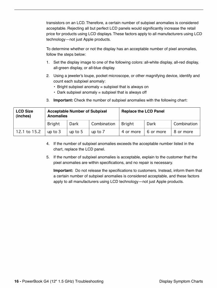
16 -
PowerBook G4 (12" 1.5 GHz) Troubleshooting Display Symptom Charts
transistors on an LCD. Therefore, a certain number of subpixel anomalies is considered acceptable. Rejecting all but perfect LCD panels would significantly increase the retail price for products using LCD displays. These factors apply to all manufacturers using LCD technology—not just Apple products.
To determine whether or not the display has an acceptable number of pixel anomalies, follow the steps below:
1. Set the display image to one of the following colors: all-white display, all-red display, all-green display, or all-blue display.
2. Using a jeweler’s loupe, pocket microscope, or other magnifying device, identify and count each subpixel anomaly:• Bright subpixel anomaly = subpixel that is always on• Dark subpixel anomaly = subpixel that is always off
3.
Important:
Check the number of subpixel anomalies with the following chart:
4. If the number of subpixel anomalies exceeds the acceptable number listed in the chart, replace the LCD panel.
5. If the number of subpixel anomalies is acceptable, explain to the customer that the pixel anomalies are within specifications, and no repair is necessary.
Important:
Do not release the specifications to customers. Instead, inform them that a certain number of subpixel anomalies is considered acceptable, and these factors apply to all manufacturers using LCD technology—not just Apple products.
LCD Size (inches)
Acceptable Number of Subpixel Anomalies
Replace the LCD Panel
Bright Dark Combination Bright Dark Combination
12.1 to 15.2 up to 3 up to 5 up to 7 4 or more 6 or more 8 or more
PowerBook G4 (12" 1.5 GHz) Troubleshooting -
17
Video (S-Video and Composite adapter) Symptom
Video (S-Video and Composite adapter)
No video on an external device
1. Make sure you are using the S-Video and Composite adapter cable.
2. Verify TV or VCR is set up properly with correct source.
3. Try different TV or VCR. Check owner’s manual for TV or VCR.
4. Replace adapter cable.
5. Replace logic board.
The display is rolling (PAL instead of NTSC)
1. Make sure you are not using Apple's A/V Video Cable.
2. Make sure you are using the S-Video and Composite adapter cable.
3. Go to Displays preference pane; change resolution from PAL setting to NTSC setting.
4. Try a different TV or VCR.
5. Try a different adapter cable
6. Replace logic board.
Display shows ghosting (signal reflection)
1. Verify that cables are correctly installed and firmly seated.
2. Replace video adapter.
Video (RGB adapter)
No video on an external device
1. Make sure RGB adapter cable is fully seated.
2. Click "Detect Displays" button to verify that monitor is being recognized in the Displays preference pane, and is known-good and supported by this computer.
3. Try known-good RGB adapter.
4. Replace logic board.
5. Replace RGB adapter cable.
6. Replace logic board.
Display shows ghosting (signal reflection)
1. Verify that cables are correctly installed and firmly seated.
2. Replace video adapter.
18 -
PowerBook G4 (12" 1.5 GHz) Troubleshooting Trackpad Symptom Charts
Trackpad
Trackpad works intermittently
The trackpad operation can be affected by hand lotion, humidity, dangling jewelry, and the use of more than one finger on the trackpad.
1. Check for environmental factors such as humidity, hand lotion, or jewelry.
2. Clean the trackpad with a clean, dry lint-free cloth.
3.
If the pointer moves as you type because you accidentally brush the trackpad, select "Ignore accidental trackpad input" in the Keyboard & Mouse pane of System Preferences.
Related articles:
17228: Portables: Jumpy or Erratic Trackpad Operation
58389: PowerBook and iBook: Trackpad Does Not Respond
The cursor does not move when you are using trackpad
1. Verify that no USB device is connected.
2. Boot from a Mac OS system CD to verify that it is not a software problem.
3. Reset the power manager by pressing the key combination Control-Option-Shift-power.
Warning: Make sure you do not hold down the "fn" key when resetting the power manager.
Warning: Resetting the power manager means you will also need to reset the date and time (using the Date & Time control panel).
4. Check trackpad cable and connection to the logic board (see separate Keyboard and Top Case replacement instructions for location under top case).
5. Replace top case.
6. Replace logic board.
The cursor intermittently does not move or moves erratically
Note:
User must touch with the surface of only one finger at a time and point directly down on the trackpad surface.
1. Clean trackpad surface (with computer off, using a non-static-inducing material).
2. Completely shut down, then press the power button to start the computer.
3. Reset the power manager by pressing the key combination Control-Option-Shift-power.
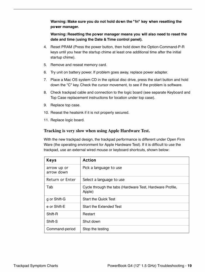
PowerBook G4 (12" 1.5 GHz) Troubleshooting -
19
Trackpad Symptom Charts
Warning: Make sure you do not hold down the "fn" key when resetting the power manager.
Warning: Resetting the power manager means you will also need to reset the date and time (using the Date & Time control panel).
4. Reset PRAM (Press the power button, then hold down the Option-Command-P-R keys until you hear the startup chime at least one additional time after the initial startup chime).
5. Remove and reseat memory card.
6. Try unit on battery power. If problem goes away, replace power adapter.
7. Place a Mac OS system CD in the optical disc drive, press the start button and hold down the "C" key. Check the cursor movement, to see if the problem is software.
8. Check trackpad cable and connection to the logic board (see separate Keyboard and Top Case replacement instructions for location under top case).
9. Replace top case.
10. Reseat the heatsink if it is not properly secured.
11. Replace logic board.
Tracking is very slow when using Apple Hardware Test.
With the new trackpad design, the trackpad performance is different under Open Firm Ware (the operating environment for Apple Hardware Test). If it is difficult to use the trackpad, use an external wired mouse or keyboard shortcuts, shown below:
KKKKeeeeyyyyssss AAAAccccttttiiiioooonnnn
arrow up or arrow down
Pick a language to use
Return or Enter Select a language to use
Tab Cycle through the tabs (Hardware Test, Hardware Profile, Apple)
g or Shift-G Start the Quick Test
e or Shift-E Start the Extended Test
Shift-R Restart
Shift-S Shut down
Command-period Stop the testing
20 - PowerBook G4 (12" 1.5 GHz) Troubleshooting Sudden Motion Sensor (SMS) Symptom Charts
Sudden Motion Sensor (SMS)
System Profiler shows Sudden Motion Sensor is “disabled.”
Note: In some locations you may see the Sudden Motion Sensor referred to as the Mobile Motion Module. Both names refer to the same feature.
1. Put the computer to sleep. Pick up the computer, and set it on a steady table top. Wake up the computer, and refresh System Profiler window under View menu (or use command-R). • If the setting changes to enable, try a few more sleep-wake-refresh sequences to
verify the circuit.• If the setting is still disabled, launch the Terminal application found in the Utilities
folder. Note: You will need the system password. At the command line, enter the command: sudo pmset -a ams 1
Now, refresh System Profiler and check if it is enabled. If so, the Sudden Motion Sensor was manually turned off. The hardware is fine.
2. If after issuing the command there is a problem with the Sudden Motion Sensor, replace the main logic board.
Dropped frames or sound elements when recording audio or video
Occasionally the Sudden Motion Sensor technology may be activated by external vibrations at a time when the PowerBook is writing data intensively, such as recording video or audio.
Apple has adjusted this feature carefully to provide the best balance between protecting the hard drive and preventing unwanted activation of the Sudden Motion Sensor. Most PowerBook G4 users will never need to turn this feature off, and Apple suggests that you not modify the settings unless absolutely necessary.
In some environments, such as live concert halls, recording studios, or dance clubs, external vibrations may be major enough to cause the sensor to unexpectedly park the hard drive heads, resulting in interrupted sound or video playback. In these situations, you may find that you want to disable the feature temporarily.
To disable the Sudden Motion Sensor:
1. From the Finder's Go menu, choose Utilities.
2. In the Utilities folder, open Terminal.
3. When the command line appears, type pmset -g # and press Return. This command queries the computer for the current setting of the Sudden Motion Sensor. The default setting is "1" (turned on).
4. If the above command returns "1," you can disable the Sudden Motion Sensor by typing sudo pmset -a ams 0 and pressing Return (changing the setting to a zero
PowerBook G4 (12" 1.5 GHz) Troubleshooting - 21Sudden Motion Sensor (SMS) Symptom Charts
disables the sensor).
5. Type your administrator password when you are prompted and press Return.
6. Type the pmset -g # command again to be sure that the setting has been applied.
Any changes that you make to the Sudden Motion Sensor setting remains in effect even after you restart the computer. If you choose to disable the Sudden Motion Sensor, Apple recommends that you re-enable it as soon as possible in order to take full advantage of the feature.
To re-enable the Sudden Motion Sensor:
1. From the Finder's Go menu, choose Utilities.
2. In the Utilities folder, open Terminal.
3. When the command line appears, type pmset -g # and press Return. If you have the Sudden Motion Sensor turned off, the command will return a zero (0).
4. If the above command returns a zero, you can re-enable the Sudden Motion Sensor by typing sudo pmset -a ams 1 and pressing Return.
5. Type your administrator password when you are prompted and press Return.
6. Type the pmset -g # command again to be sure that the setting has been applied.
Note: The Sudden Motion Sensor will not prevent hard drive failures. Its primarily function is to prepare the hard drive for the impact of an accidental drop or severe vibration. It does not assist in the other ways hard drives fail.
22 - PowerBook G4 (12" 1.5 GHz) Troubleshooting Misc. Symptoms Symptom Charts
Misc. Symptoms
The computer runs with battery, but not with the power adapter plugged into wall outlet
1. Try known-good power outlet.
2. Try known-good power adapter and power cord.
Note: Verify that power adapter connector glows amber or green. If the power adapter light is green, turn over the computer and press the battery button. One to five lights glow to show the battery’s level of charge. One blinking light indicates that the battery does not have sufficient charge to turn on.
3. Reset the power manager by pressing the key combination Control-Option-Shift-power.
Warning: Make sure you do not hold down the "fn" key when resetting the power manager.
Warning: Resetting the power manager means you will also need to reset the date and time (using the Date & Time control panel).
4. Replace DC-in board
5. Replace DC-to-DC board.
6. Replace logic board.
The computer runs when plugged into a wall outlet but not on battery power
1. Reseat battery to verify battery is seated correctly with battery lock engaged.
2. Try known-good charged battery.
3. Reset the power manager by pressing key combination Control-Option-Shift-power.
Warning: Make sure you do not hold down the "fn" key when resetting the power manager.
Warning: Resetting the power manager means you will also need to reset the date and time (using the Date & Time control panel).
4. Replace DC-to-DC board.
5. Replace logic board.
The microphone is not working
1. In the Sound preference pane select the Input tab. Make sure that the internal microphone device is selected in the list.
2. In the Sound preference pane select the Input tab. Make sure that the input volume is midrange or above.
PowerBook G4 (12" 1.5 GHz) Troubleshooting - 23Misc. Symptoms Symptom Charts
3. In the Sound preference pane select the Output tab. Make sure the built-in audio controller is selected.
4. Create new Mac OS X user and log in as that user. (So that the customer does not question the new user, remove the user once disc is verified.)
5. Reset PRAM (Press the power button, then hold down the Option-Command-P-R keys until you hear the startup chime at least one additional time after the initial startup chime).
6. Verify microphone cable connection to logic board.
7. Replace top case (which includes the microphone).
8. Replace logic board.
The latching mechanism that holds the display closed is not working
Note: As the display closes against the top case, a hook in the top of the display housing should be magnetically pulled down into a slot in the top case, and secured. When the latch button is pushed, the hook should release and retract into the display housing, allowing the display to open.
1. Verify hook operation by exercising the latch mechanism.
2. If the hook does not operate properly, replace the display bezel.
3. If the latch or latch button does not operate properly, replace the bottom case assembly.
Fan fails
1. Check fan cable connection, and check cable for damage.
2. Replace fan.
3. Replace logic board.
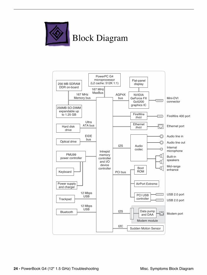
24 - PowerBook G4 (12" 1.5 GHz) Troubleshooting Misc. Symptoms Block Diagram
Block Diagram
PCI bus
I2S
I2S
12 MbpsUSB
12 MbpsUSB
Mini-DVIconnector
Ethernet port
FireWire 400 port
Built-inspeakers
Mid-rangeenhance
Audio line in
Internalmicrophone
AGP4Xbus
167 MHzMemory bus
167 MHzMaxBus
Intrepidmemorycontrollerand I/Odevice
controller
PMU99power controller
Trackpad
Keyboard
Power supplyand charger
Optical drive
256MB SO-DIMMexpandable up
to 1.25 GB
UltraATA bus
EIDEbus
Audio line out
Hard diskdrive
NVIDIAGeForce FX
Go5200graphics IC
Flat-paneldisplay
Audiocodec
EthernetPHY
FireWirePHY
PowerPC G4microprocessor
(L2 cache: 512K 1:1)256 MB SDRAMDDR on-board
Modem port
Modem module
Bluetooth
BootROM
USB 2.0 port
USB 2.0 port
PCI USBcontroller
Data pumpand DAA
AirPort Extreme
I2CSudden Motion Sensor
© 2005 Apple Computer, Inc. All rights reserved.
Service Source
Views
PowerBook G4 (12-inch 1.5 GHz)
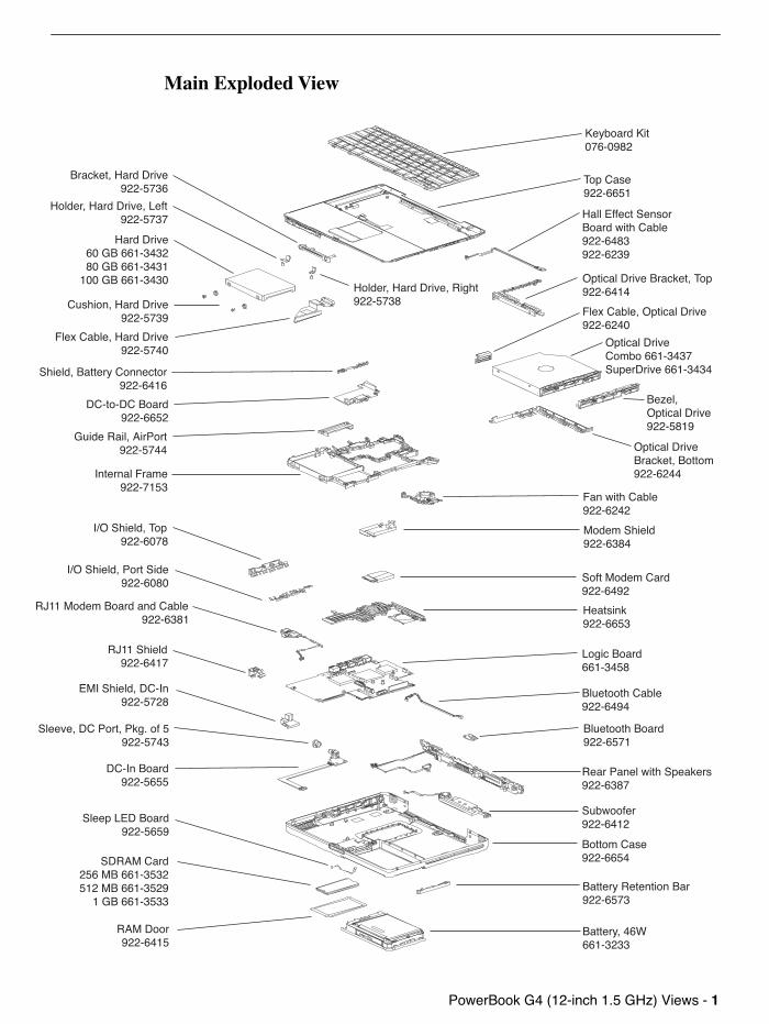
PowerBook G4 (12-inch 1.5 GHz) Views -
1
Main Exploded View
Keyboard Kit076-0982
Top Case922-6651����������������
Optical Drive Bracket, Top922-6414
Hall Effect SensorBoard with Cable922-6483922-6239
Optical DriveCombo 661-3437SuperDrive 661-3434
Bezel,Optical Drive922-5819
Optical Drive Bracket, Bottom922-6244
Flex Cable, Optical Drive922-6240
Bracket, Hard Drive922-5736
Holder, Hard Drive, Left922-5737
Hard Drive60 GB 661-343280 GB 661-3431
100 GB 661-3430
Cushion, Hard Drive922-5739
Flex Cable, Hard Drive922-5740
Holder, Hard Drive, Right922-5738
Shield, Battery Connector922-6416
DC-to-DC Board922-6652
Guide Rail, AirPort922-5744
Internal Frame922-7153
Fan with Cable922-6242
Modem Shield922-6384
Soft Modem Card922-6492
Heatsink922-6653
Logic Board661-3458
Bluetooth Cable922-6494
Rear Panel with Speakers922-6387
Subwoofer922-6412
Bottom Case922-6654
Battery Retention Bar922-6573
Battery, 46W661-3233
I/O Shield, Top922-6078
I/O Shield, Port Side922-6080
RJ11 Modem Board and Cable922-6381
DC-In Board922-5655
SDRAM Card 256 MB 661-3532512 MB 661-3529
1 GB 661-3533
RAM Door922-6415
Bluetooth Board922-6571
Sleep LED Board922-5659
EMI Shield, DC-In922-5728
Sleeve, DC Port, Pkg. of 5922-5743
RJ11 Shield922-6417
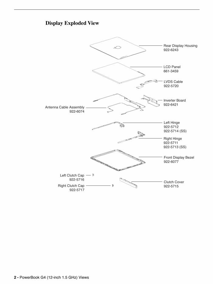
2 -
PowerBook G4 (12-inch 1.5 GHz) Views
Display Exploded View
Rear Display Housing922-6243
Inverter Board922-6421
LCD Panel661-3459
LVDS Cable922-5720
Left Hinge922-5712922-5714 (SS)
Right Hinge922-5711922-5713 (SS)
Front Display Bezel922-6077
Clutch Cover922-5715Right Clutch Cap
922-5717
Left Clutch Cap922-5716
Antenna Cable Assembly922-6074

PowerBook G4 (12-inch 1.5 GHz) Views -
3
PowerBook G4 (12-inch 1.5 GHz) Screw Locator - 1 of 12
Note:
Screw lengths are approximate.
Memory Door (4) Phillips, 922-5912
2.5mm 2.5mm
2.5mm 2.5mm
14mm
5 100
5 100
Keyboard(1) Phillips, 922-5918
(2) Phillips, 922-5910
2mm 2mm5 100
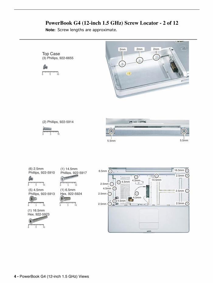
4 -
PowerBook G4 (12-inch 1.5 GHz) Views
PowerBook G4 (12-inch 1.5 GHz) Screw Locator - 2 of 12
Note:
Screw lengths are approximate.
2mm 2mm 2mm
5.5mm 5.5mm
Top Case(3) Phillips, 922-6655
5 100
5 100
5 100
5 100
5 100
(2) Phillips, 922-5914
(6) 2.5mmPhillips, 922-5910
(1) 14.5mmPhillips, 922-5917
(5) 4.5mmPhillips, 922-5913
(1) 16.5mmHex, 922-5923
5 100
(1) 6.5mmHex, 922-5924
5 100
6.5mm 16.5mm
2.5mm
2.5mm
2.5mm
2.5mm
2.5mm
2.5mm
4.5mm4.5mm
4.5mm 4.5mm
4.5mm
14.5mm
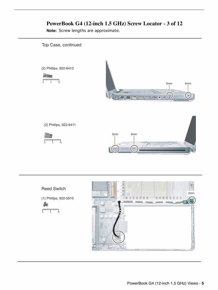
PowerBook G4 (12-inch 1.5 GHz) Views -
5
PowerBook G4 (12-inch 1.5 GHz) Screw Locator - 3 of 12
Note:
Screw lengths are approximate.
5mm 5mm
5 100
5 100
Reed Switch
(1) Phillips, 922-5910
(2) Phillips, 922-6410
3mm 3mm
(2) Phillips, 922-6411
5 100
Top Case, continued
2mm
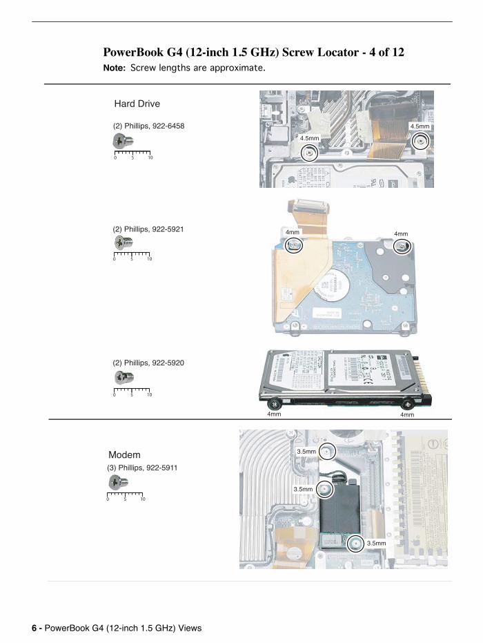
6 -
PowerBook G4 (12-inch 1.5 GHz) Views
PowerBook G4 (12-inch 1.5 GHz) Screw Locator - 4 of 12
Note:
Screw lengths are approximate.
4.5mm
4.5mm
4mm4mm
4mm4mm
5 100
5 100
5 100
Hard Drive
(2) Phillips, 922-6458
(2) Phillips, 922-5921
(2) Phillips, 922-5920
Modem(3) Phillips, 922-5911
5 100
3.5mm
3.5mm
3.5mm
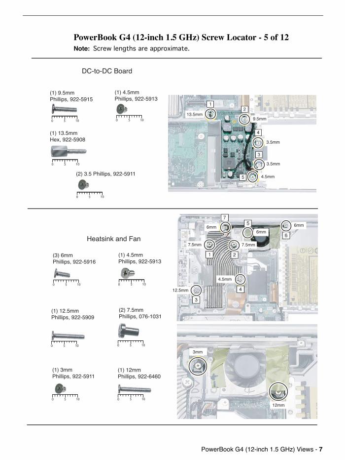
PowerBook G4 (12-inch 1.5 GHz) Views -
7
PowerBook G4 (12-inch 1.5 GHz) Screw Locator - 5 of 12
Note:
Screw lengths are approximate.
5 100
5 100
5 1005 100
Heatsink and Fan
(2) 3.5 Phillips, 922-5911
(3) 6mmPhillips, 922-5916
(1) 3mmPhillips, 922-5911
5 100
5 100
(1) 12.5mmPhillips, 922-5909
DC-to-DC Board
5 100
5 100 5 100
(1) 13.5mmHex, 922-5908
(1) 9.5mm Phillips, 922-5915
(1) 4.5mm Phillips, 922-5913
12.5mm
7.5mm 7.5mm
6mm6mm 6mm
4.5mm
3.5mm
4.5mm
3.5mm
9.5mm13.5mm
3mm
12mm
(1) 4.5mmPhillips, 922-5913
(2) 7.5mmPhillips, 076-1031
5 100
(1) 12mmPhillips, 922-6460
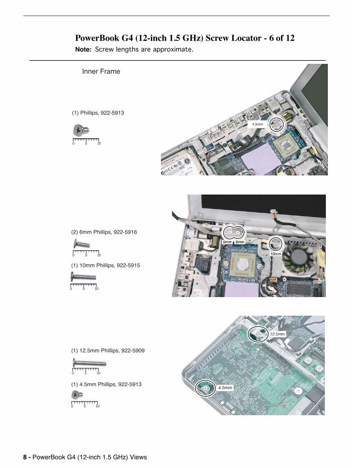
8 -
PowerBook G4 (12-inch 1.5 GHz) Views
PowerBook G4 (12-inch 1.5 GHz) Screw Locator - 6 of 12
Note:
Screw lengths are approximate.
5 100
4.5mm
(1) Phillips, 922-5913
Inner Frame
(2) 6mm Phillips, 922-5916
(1) 10mm Phillips, 922-5915
5 100
(1) 12.5mm Phillips, 922-5909
(1) 4.5mm Phillips, 922-5913
5 100
5 100
5 100
4.5mm
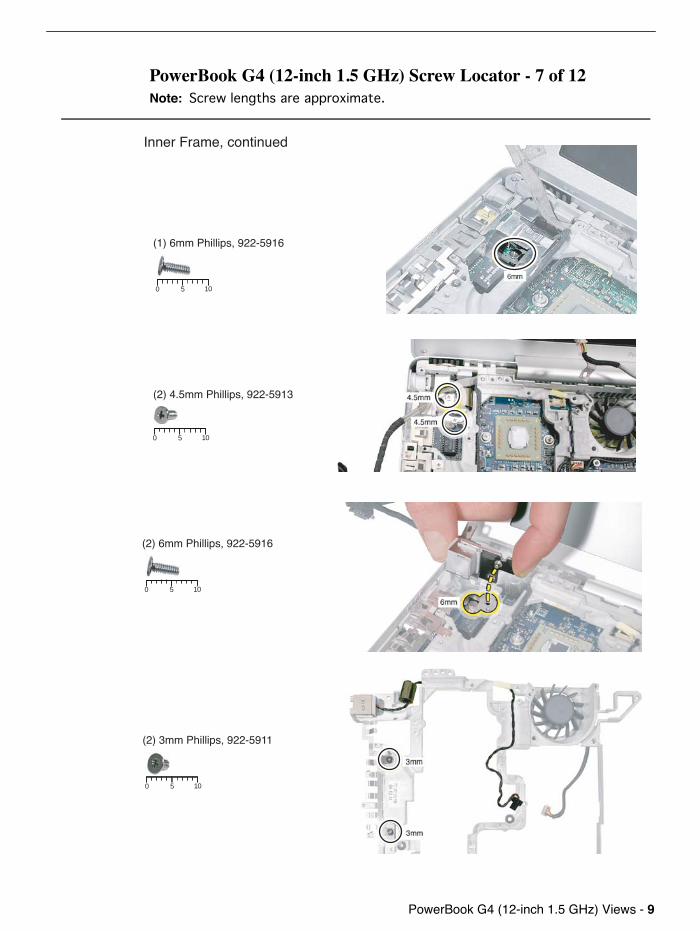
PowerBook G4 (12-inch 1.5 GHz) Views -
9
PowerBook G4 (12-inch 1.5 GHz) Screw Locator - 7 of 12
Note:
Screw lengths are approximate.
(1) 6mm Phillips, 922-5916
5 100
5 100
(2) 4.5mm Phillips, 922-5913
Inner Frame, continued
(2) 6mm Phillips, 922-5916
5 100
(2) 3mm Phillips, 922-5911
5 100
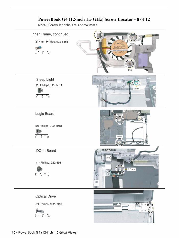
10 -
PowerBook G4 (12-inch 1.5 GHz) Views
PowerBook G4 (12-inch 1.5 GHz) Screw Locator - 8 of 12
Note:
Screw lengths are approximate.
Logic Board
(2) Phillips, 922-5913
5 100
Sleep Light
(1) Phillips, 922-5911
5 100
DC-In Board
(1) Phillips, 922-5911
5 100
Optical Drive
(2) Phillips, 922-5916
5 100
(3) 4mm Phillips, 922-6656
5 100
Inner Frame, continued
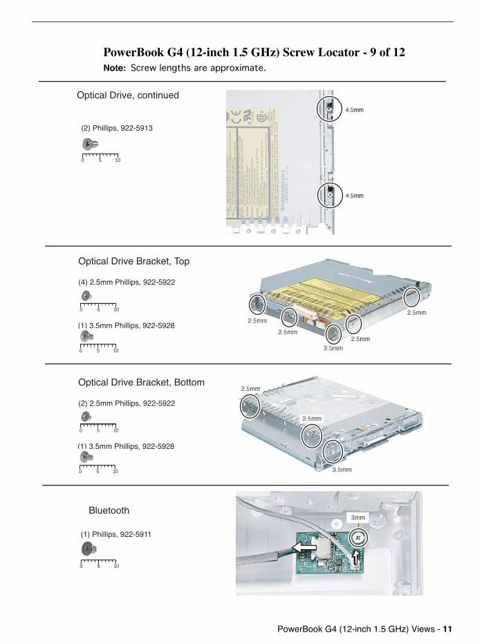
PowerBook G4 (12-inch 1.5 GHz) Views -
11
PowerBook G4 (12-inch 1.5 GHz) Screw Locator - 9 of 12
Note:
Screw lengths are approximate.
5 100
Optical Drive Bracket, Top
(4) 2.5mm Phillips, 922-5922
(1) 3.5mm Phillips, 922-5928
5 100
(2) Phillips, 922-5913
5 100
Bluetooth
Optical Drive Bracket, Bottom
(2) 2.5mm Phillips, 922-5922
5 100
(1) 3.5mm Phillips, 922-5928
5 100
(1) Phillips, 922-5911
5 100
Optical Drive, continued
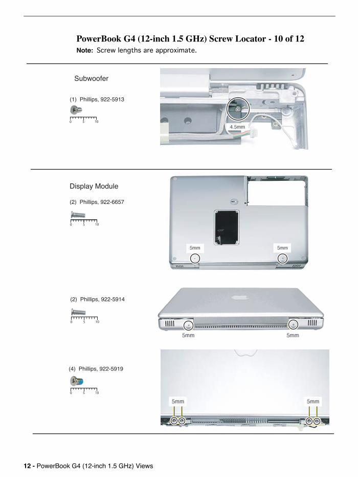
12 -
PowerBook G4 (12-inch 1.5 GHz) Views
PowerBook G4 (12-inch 1.5 GHz) Screw Locator - 10 of 12
Note:
Screw lengths are approximate.
Display Module
(2) Phillips, 922-6657
5 100
Subwoofer
5 100
(1) Phillips, 922-5913
(2) Phillips, 922-5914
(4) Phillips, 922-5919
5 100
5 100
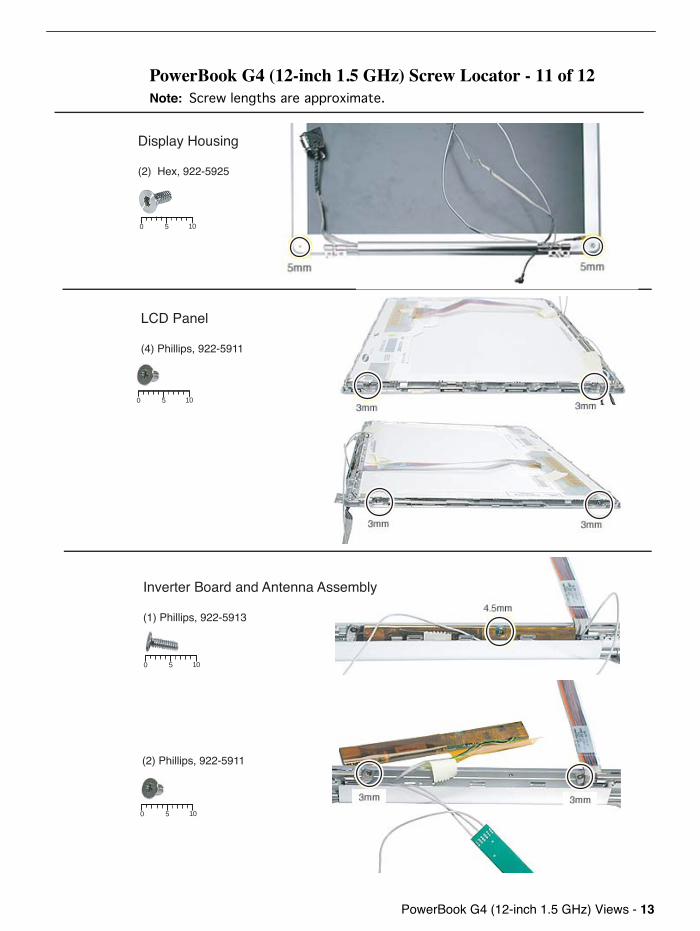
PowerBook G4 (12-inch 1.5 GHz) Views -
13
PowerBook G4 (12-inch 1.5 GHz) Screw Locator - 11 of 12
Note:
Screw lengths are approximate.
LCD Panel
(4) Phillips, 922-5911
5 100
5 100
Display Housing
(2) Hex, 922-5925
Inverter Board and Antenna Assembly
(1) Phillips, 922-5913
(2) Phillips, 922-5911
5 100
5 100
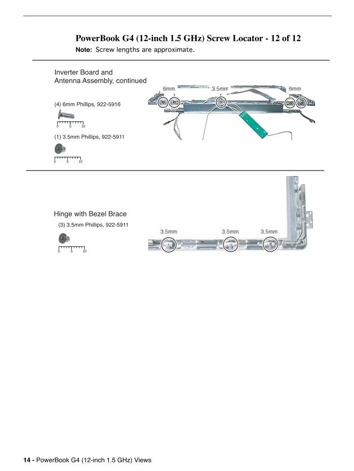
14 -
PowerBook G4 (12-inch 1.5 GHz) Views
PowerBook G4 (12-inch 1.5 GHz) Screw Locator - 12 of 12
Note:
Screw lengths are approximate.
(3) 3.5mm Phillips, 922-5911
5 100
5 100
5 100
Inverter Board andAntenna Assembly, continued
(4) 6mm Phillips, 922-5916
(1) 3.5mm Phillips, 922-5911
Hinge with Bezel Brace

PowerBook G4 (12-inch 1.5 GHz) Views -
15
Screw Reference Chart - 1 of 2
Memory Door
922-5912076-1032
922-5918076-1030
922-5910
922-5914 922-5917 922-5924
922-5913 922-5923
922-6410 922-5911
922-5921 922-5920 922-5915
KeyboardKeyboard, Top Case,Reed Switch
Top Case, Display Module Top Case
Top Case, DC-to-DC Board, Heatsink, Inner Frame,Logic Board, Optical Drive, Subwoofer, Inverter Board Top Case
Top Case (Left Side)
Modem, DC-to-DC Board, Heatsink, Inner Frame, Sleep Light,DC-In Board, Bluetooth, LCD Panel, Inverter Board, Hinge with Bezel Brace
Hard Drive Hard Drive DC-to-DC Board, Inner Frame
5 100 5 100 5 100
5 100 5 100 5 100
5 100 5 100
5 100 5 100
5 100 5 100 5 100
Top Case
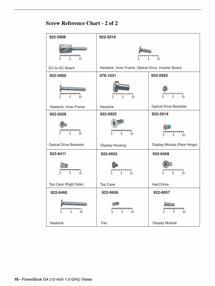
16 -
PowerBook G4 (12-inch 1.5 GHz) Views
Screw Reference Chart - 2 of 2
DC-to-DC Board
922-5908 922-5916
922-5909 076-1031 922-5922
922-5928 922-5925
Heatsink, Inner Frame, Optical Drive, Inverter Board
Heatsink, Inner Frame Heatsink Optical Drive Brackets
Optical Drive Brackets Display Housing
5 100 5 100
5 100 5 100 5 100
5 100 5 100
922-5919
Display Module (Rear Hinge)
5 100
922-6411
Top Case (Right Side)
5 100
922-6655
Top Case
5 100
922-6458
Hard Drive
5 100
922-6657
Display Module
5 100
922-6460
Heatsink
5 100
922-6656
Fan
5 100