power technology - powerplants.mandieselturbo.com · tion, man diesel & turbo has the power...
TRANSCRIPT

Power TechnologyFor a greener planet

3Power Technology – For a greener planetMAN Diesel – Footnotes
MAN Diesel & Turbo is one of the world’s leading suppliers of diesel and gas
engine power plants, both land-based and floating. Over the last century, we have
built thousands of diesel power plants worldwide. The experience we have gained
and the technology we have developed over that time enables our specialists to
tailor power plants to the individual needs of customers all over the world.
During this long history, the companies within the MAN Group have always been
world leaders in their fields, both in design engineering and the commercial appli-
cation of new technologies. More recently, we have pioneered the innovative inte-
gration of mechanical engineering with state-of-the-art electronics.
More than ever before, MAN Diesel & Turbo is focusing on the environmental
performance of our engines. Using our unrivalled grasp of large engine tech-
nology, we aim to make our engines progressively cleaner, more powerful and
more efficient.
With our firm commitment to reducing emissions while increasing fuel efficiency
and power density, and with our active partnership with environmental institutions
and development banks, we intend to be part of the global emissions solution.
4 Power Technology – For a greener planet 5Power Technology – For a greener planet
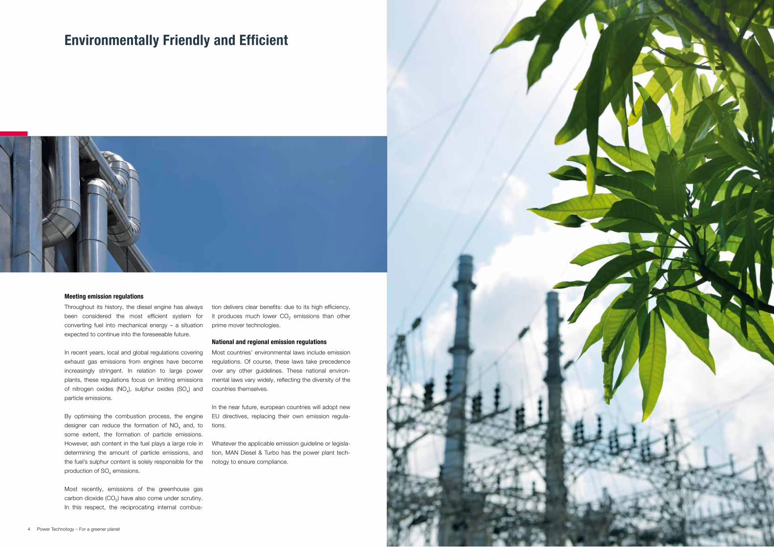
Environmentally Friendly and Efficient
Meeting emission regulations
Throughout its history, the diesel engine has always
been considered the most efficient system for
converting fuel into mechanical energy – a situation
expected to continue into the foreseeable future.
In recent years, local and global regulations covering
exhaust gas emissions from engines have become
increasingly stringent. In relation to large power
plants, these regulations focus on limiting emissions
of nitrogen oxides (NOx), sulphur oxides (SOx) and
particle emissions.
By optimising the combustion process, the engine
designer can reduce the formation of NOx and, to
some extent, the formation of particle emissions.
However, ash content in the fuel plays a large role in
determining the amount of particle emissions, and
the fuel’s sulphur content is solely responsible for the
production of SOx emissions.
Most recently, emissions of the greenhouse gas
carbon dioxide (CO2) have also come under scrutiny.
In this respect, the reciprocating internal combus-
tion delivers clear benefits: due to its high efficiency,
it produces much lower CO2 emissions than other
prime mover technologies.
National and regional emission regulations
Most countries’ environmental laws include emission
regulations. Of course, these laws take precedence
over any other guidelines. These national environ-
mental laws vary widely, reflecting the diversity of the
countries themselves.
In the near future, european countries will adopt new
EU directives, replacing their own emission regula-
tions.
Whatever the applicable emission guideline or legisla-
tion, MAN Diesel & Turbo has the power plant tech-
nology to ensure compliance.

6 Power Technology – For a greener planet 7Power Technology – For a greener planet
Maximum Emission Reduction
All values
referenced to
15% O2
Air shed class.
Natural gas
Liquid
fuels
Biofuels
all power plant sizes
Air shed class.
Biofuels
Gas fuels
other than nat. gas
PM
mg/Nm3
n/a
50-100
a)
PM
mg/Nm3
PM
mg/Nm3
Small Power Plants
3 MWth to ≤ 50 MWth (Fuel Input)
Medium Power Plants
> 50 MWth to < 300 MWth (Fuel Input)
S in fuel %
(SO2)
(mg/Nm3)
n/a
1.5-3.0
(870-1750) b)
S in fuel %
(SO2)
(mg/Nm3)
S in fuel %
(SO2)
(mg/Nm3)
NOx
mg/Nm3
200 (spark ignited)
400 (dual-fuel)
1600 (compression ign.)
1460-1600 (bore<400) c)
1850 (bore≥400)
NOx
mg/Nm3
NOx
mg/Nm3
NDA
n/a
50
NDA
n/a
2
(1170)
NDADA
n/a
30
DA
n/a
0.5
(290)
DA
1400 (bore<400) 1850 (bore>400)
2000 (DF)400
NDA
50
NDA
n/a
NDADA
30
DA
n/a
DA
30% higher than those for nat. gas or liquids
PM
mg/Nm3
Large Power Plants
≥ 300 MWth (Fuel Input)
S in fuel %
(SO2)
(mg/Nm3)
NOx
mg/Nm3
NDA
n/a
50
NDA
n/a
1
(580)
NDADA
n/a
30
DA
n/a
0.2
(116)
DA
740 d) 400
All values
referenced to
15% O2
Air shed class.
Natural gas
Liquid
fuels
200 (spark ign.) 400 (dual-fuel)
Foot notes:
a) Up to 100 mg/Nm3 is permitted if justified by project specific
consideration (e.g. economic feasibility of using low ash fuel
or adding ESP to meet 50mg/Nm3, and available environ-
mental capacity at site).
b) Up to 3% S is permitted if justified by project specific con-
siderations (e.g. economic feasibility of using low S fuel or
adding FGD and available environmental capacity at site).
c) For bore diameter < 400mm up to 1600 mg/Nm3 is permit-
ted if justified to maintain energy efficiency.
d) For all bore diameters, contingent upon water availability
World Bank emission guidelines
In 2007 and 2008, the World Bank’s commercial
finance arm, the International Finance Corporation
(IFC), published new environmental, health and
safety guidelines. These guidelines are applicable in
all cases where financing is based on World Bank
conditions, such as financing by development banks,
or where financing is supported by export credit
agencies. Many countries have also adopted the
World Bank guidelines into their local emission regu-
lations.
The World Bank guidelines categorise power plants
based on the fuel used – gas, liquid or biofuels.
Within each category, emission levels are set
according to the power plant’s size. The larger the
power plant, the more stringent the emission limits.
For more details, please refer to the World Bank
guideline emission levels in the table on this page.
It should be noted that the World Bank emission
guidelines are guidelines only and do not have the
power of law. In other words, they are a flexible
instrument: emission limits may be adjusted higher or
lower for a specific project, if justified by an environ-
mental assessment study.
400
Air shed classification:
NDA: non-degraded air shed
Means: no or few pollution existing at site
DA: degraded air shed
Means: significant pollution already existing at site
Data for information only
200 (spark ign.) 400 (dual-fuel)
8 Power Technology – For a greener planet 9Power Technology – For a greener planet
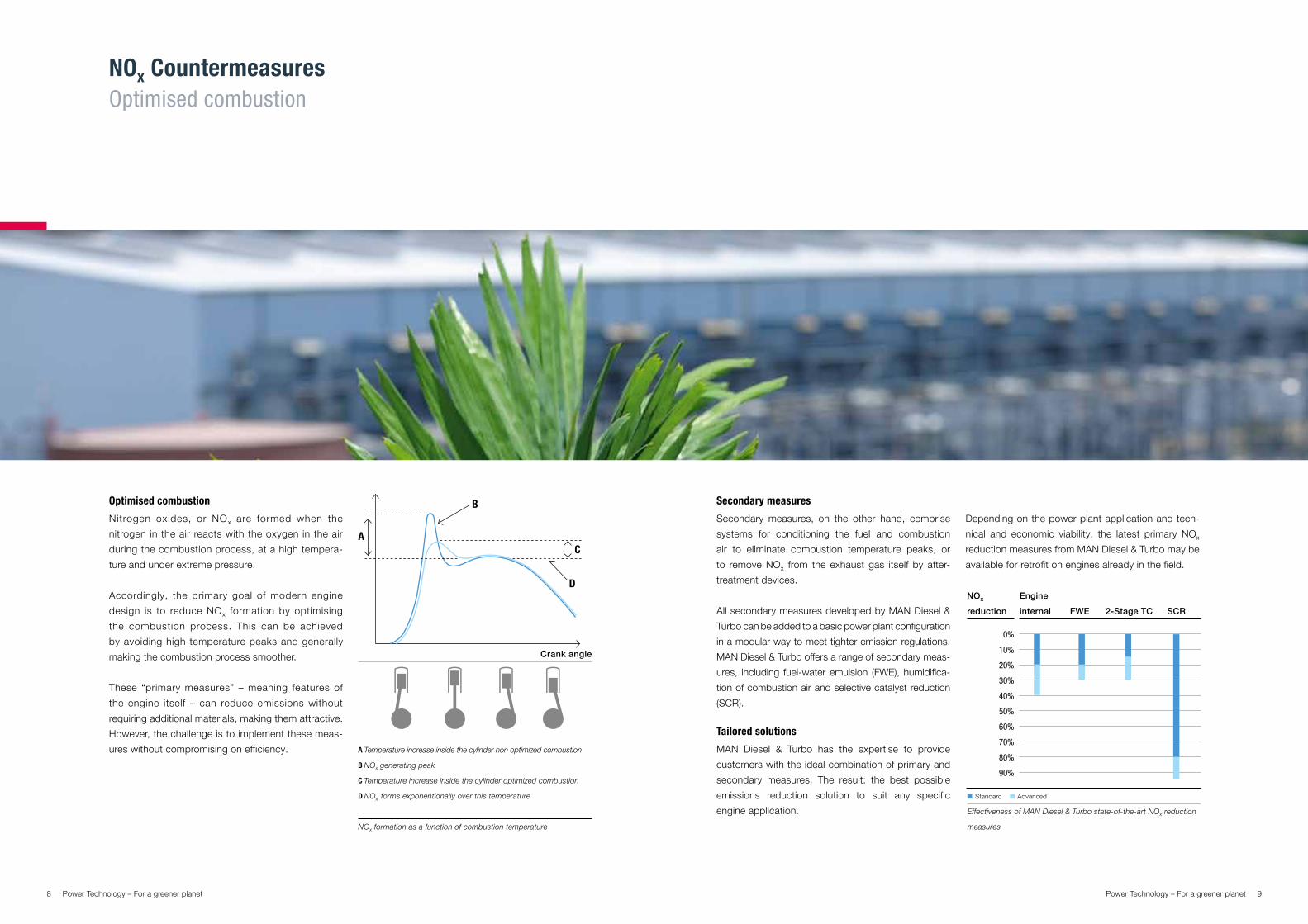
NOx CountermeasuresOptimised combustion
Optimised combustion
Nitrogen oxides, or NOx are formed when the
nitrogen in the air reacts with the oxygen in the air
during the combustion process, at a high tempera-
ture and under extreme pressure.
Accordingly, the primary goal of modern engine
design is to reduce NOx formation by optimising
the combustion process. This can be achieved
by avoiding high temperature peaks and generally
making the combustion process smoother.
These “primary measures” – meaning features of
the engine itself – can reduce emissions without
requiring additional materials, making them attractive.
However, the challenge is to implement these meas-
ures without compromising on efficiency.
Secondary measures
Secondary measures, on the other hand, comprise
systems for conditioning the fuel and combustion
air to eliminate combustion temperature peaks, or
to remove NOx from the exhaust gas itself by after-
treatment devices.
All secondary measures developed by MAN Diesel &
Turbo can be added to a basic power plant configuration
in a modular way to meet tighter emission regulations.
MAN Diesel & Turbo offers a range of secondary meas-
ures, including fuel-water emulsion (FWE), humidifica-
tion of combustion air and selective catalyst reduction
(SCR).
Tailored solutions
MAN Diesel & Turbo has the expertise to provide
customers with the ideal combination of primary and
secondary measures. The result: the best possible
emissions reduction solution to suit any specific
engine application.
NOx formation as a function of combustion temperature
A Temperature increase inside the cylinder non optimized combustion
B NOx generating peak
C Temperature increase inside the cylinder optimized combustion
D NOx forms exponentionally over this temperature
Effectiveness of MAN Diesel & Turbo state-of-the-art NOx reduction
measures
Standard Advanced
NOx
reduction
Engine
internal FWE SCR2-Stage TC
Crank angle
Depending on the power plant application and tech-
nical and economic viability, the latest primary NOx
reduction measures from MAN Diesel & Turbo may be
available for retrofit on engines already in the field.
0%
10%
20%
30%
40%
50%
60%
70%
80%
90%

10 Power Technology – For a greener planet 11Power Technology – For a greener planet
Combustion chamber geometry
Optimising the mix of fuel and air in the cylinder
achieves more complete, homogenous combus-
tion, avoiding temperature peaks (“hot spots”) which
cause over 90% of NOx formation.
The new low-swirl cylinder heads and high compres-
sion re-entrant pistons designed by MAN Diesel & Turbo
improve gas flow, decreasing NOx formation.
The combustion temperature – and as a result, the
NOx formation – may also be decreased by retarded
injection. However, this measure increases the
specific fuel consumption – what is known as the
“diesel dilemma”.
Advanced injection control by common rail
The common rail fuel injection system developed by
MAN Diesel & Turbo allows extremely precise and
flexible control of injection pressure, timing and dura-
tion across the entire engine load range.
While conventional injection systems are designed to
function best at a particular point of operations, i.e.
full load operation, the common rail injection system
allows optimal engine performance, emissions and
fuel consumption across a wide spectrum of part
loads.
The MAN Diesel & Turbo common rail fuel injection system
NOx CountermeasuresOptimised combustion
Effects of MAN Diesel & Turbo´s advanced primary NOx reduction
measures
SFOC
NOx
Optimised combustion Miller Cycle High efficiency turbocharging
Miller Cycle / Variable valve timing
The Miller Cycle is a technique involving the early
closure of the inlet valves before the piston reaches
its lowest centre position. This causes the intake air
to expand and cool after the inlet valve has closed.
As a result, combustion temperature peaks at a lower
level, reducing NOx formation.
However, MAN Diesel & Turbo’s variable valve timing
(VVT) technology and highly efficient turbochargers,
with their increased pressure ratios and variable
turbine area (VTA), overcome this drawback, main-
taining clean combustion over an extremely wide
operation range.

12 Power Technology – For a greener planet 13Power Technology – For a greener planet
Two-stage turbocharging
Two-stage turbocharging, also known as called
sequential turbocharging (STC) consists of two turbo-
chargers operating in sequence. This allows very high
combustion air pressure ratios, opening up a whole
new dimension of operational possibilities.
The excess combustion air can be used for enhanced
Miller Cycling with significant fuel savings – and further
reducing NOx emissions.
Alternatively, the excess of combustion air can be
leveraged to significantly increase the engine power
output. Although this does not save as much fuel,
it does allow a greater reduction of NOx emissions
within a wide operation range.
Two-stage turbocharging is a modular system located
upstream from the engine, designed in a way that
enables most MAN Diesel & Turbo power plants to
be retrofitted.
Po
wer
out
put
[%]
NO
x re
duc
tion
[%]
Effects of Two-Stage Turbocharging
Op. mode
16
12
8
4
0
0
-5
-10
-15
-20
-25
-30
1 2 3 4
Fue
l co
nsum
ptio
n [%
]
0
-0,5
-1
-1,5
-2
-2,5
1 2 3 4Op. mode
NOx CountermeasuresTwo-stage turbocharging
Two-stage turbocharging principle
Combustion air to engine
Exhaust gas from engine

14 Power Technology – For a greener planet 15Power Technology – For a greener planet
NOx CountermeasuresWet solutions & after-treatment
Catalytic after-treatment
Catalytic after-treatment entails inducing chemical
reactions in the exhaust gas to break down harmful
substances like NOx into harmless components such
as nitrogen and water. This can only be achieved with
a catalytic reactor.
Selective catalytic reduction (SCR) of NOx
Selective catalytic reduction involves injecting a
reducing agent – such as ammonia or urea – into the
exhaust gas flow upstream from a catalytic reactor.
Hydrous urea solution, which is easier to handle, is
more suitable for this process than ammonia.
In the exhaust gas stream, urea decomposes into
ammonia and CO2. The ammonia reacts with NOx
on the surfaces of the catalytic reactor and reduces
NOx to nitrogen and water. The system is capable of
reducing the NOx levels in exhaust gases by around
80% – in advanced systems with larger reactors and
high urea consumption even up to 95%.
Selective catalytic reduction is sensitive to SO2 in the
exhaust gas, which reacts with the ammonia to form
ammonia sulphate. This forms deposits which can
clog the catalyst and greatly reduce its effectiveness.
Depending on exhaust gas temperatures, reliable
SCR operation requires fuel with low sulphur content.
If a SCR is used to reduce NOx in the exhaust gas,
the engine can be operated at full load with maximum
efficiency: no NOx reduction measures are required in
the engine itself. This advantage offsets the additional
effort involved in operating a SCR system.
As with primary measures, wet technologies aim to
eliminate the temperature peaks responsible for the
majority of NOx formation. MAN Diesel & Turbo offers
two wet technologies, fuel-water emulsification (FWE)
and combustion air humidification.
Fuel-water emulsification (FWE)
In the fuel-water emulsification process, water is
mixed with fuel and emulsified in a special FWE
module upstream from the engine. The emulsion can
be made of up to 30% of water and 70% liquid fuel.
The emulsion is then injected into the combustion
chamber. During the combustion process, the water
evaporates, reducing the combustion temperature,
and as a result, NOx formation. Evaporating water
atomises fuel very effectively, making the combustion
process even more homogenous.
Humidification of combustion air
NOx formation during combustion also depends
significantly on humidity in the combustion air. The
lower the humidity, the higher the NOx level in the
exhaust gas, and vice versa.
Accordingly, in the event of low ambient air humidity,
water can be sprayed onto the combustion air
upstream from the turbocharger. This can be done
until the saturation limit has been reached.
Typical minimum temperature required at SCR inlet to avoid ammo-
nium sulphate formation for fuels with varying sulphur contents.
Sulphur content [%]
0 0,5 1 1,5 2 2,5 3 3,5 4250
270
290
310
330
350
370
Urea solution
Sample gas
Air
Control signal
Urea tank
Air compressor
Injection
Dosing unit
Emission monitoring system
Exhaust gas out
Urea injectionStatic mixers
CatalystExhaust gas out
Catalyst layers
Urea supply pump
Exhaust gas in

16 Power Technology – For a greener planet 17Power Technology – For a greener planet
SOx Countermeasures
SO
x em
issi
ons
[m
g/N
m3
@ 1
5% O
2]
0 1 2 3 4 5
Fuel S-content [%wt]
SOx Emissions vs. Fuel S-Content
3000
2500
2000
1500
1000
500
0
Sulphur in, sulphur out
SOx emissions are solely the result of the sulphur
content in the fuel – they cannot be influenced by the
engine. Any sulphur burned will be emitted as SO2 or
SO3 in the exhaust gas. This means that SOx emis-
sions can only be reduced by secondary measures,
i.e. fuel conditioning or exhaust gas after-treatment.
Low sulphur fuels
Low sulphur fuels are the most obvious way to
prevent SOx emissions. But low sulphur fuel is not
always available, and removing sulphur from the fuel
often can be costly.
No-sulphur fuel: natural gas and biofuels
In 2006, MAN Diesel & Turbo introduced its latest
dual-fuel engine, the 51/60DF. This can run on either
gaseous fuel ignited by 1% distillate fuel micro-pilot
injection or on 100% liquid fuel (distillate or heavy fuel
oil).
MAN Diesel & Turbo’s dual-fuel technology features
seamless switchover between gaseous and liquid
fuels at any load.
A cost-effective and efficient derivate from the
51/60DF engine is the 51/60G gas engine, running
on gas only. Its outstanding efficiency and clean
emissions make this engine ideal for co-generation
power plants, even in dense urban areas.
Because the 51/60DF and the 51/60G engines are
derivates from the popular 48/60 diesel engine,
these technologies can be easily retrofitted on the
48/60 heavy fuel oil engine for any application. Many
MAN Diesel & Turbo engines also can be operated on
biofuels, which do not contain sulphur.
Exhaust gas scrubbing
If low sulphur fuel or natural gas is not available, SOx
has to be removed from the exhaust gas by scrub-
bing with alkaline material. In diesel power plants,
three different methods of scrubbing are generally
used:
Wet scrubbing with diluted milk of lime Semi-dry scrubbing with limestone slurry and
spray absorbers Dry scrubbing with hydrated lime
Which of these three scrubbing methods is deployed
depends mainly on the amount and quality of water
available. Another factor is the white smoke plume
caused by wet scrubbing, which may not be accept-
able in environmentally-sensitive or urban areas.
Moreover, semi-dry and dry scrubbing with a fabric
filter system can only can be used if exhaust gas is
cooled down by a boiler to a maximum of 200°C.
The three methods have different investment costs
and operational costs. For example, wet scrubbing
involves higher investment, but lower operational
costs than dry scrubbing.
18 Power Technology – For a greener planet 19Power Technology – For a greener planet
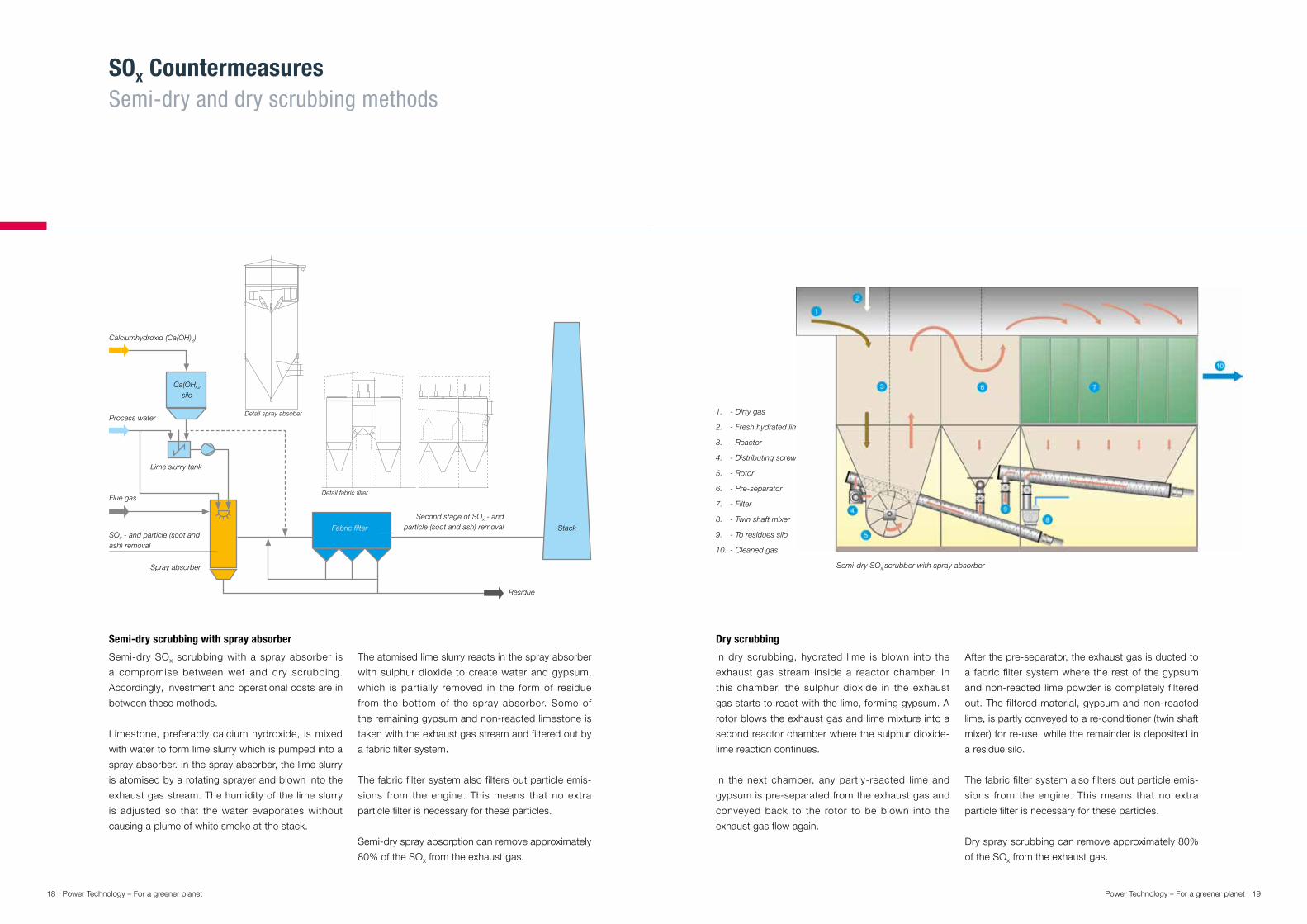
SOx CountermeasuresSemi-dry and dry scrubbing methods
Semi-dry scrubbing with spray absorber
Semi-dry SOx scrubbing with a spray absorber is
a compromise between wet and dry scrubbing.
Accordingly, investment and operational costs are in
between these methods.
Limestone, preferably calcium hydroxide, is mixed
with water to form lime slurry which is pumped into a
spray absorber. In the spray absorber, the lime slurry
is atomised by a rotating sprayer and blown into the
exhaust gas stream. The humidity of the lime slurry
is adjusted so that the water evaporates without
causing a plume of white smoke at the stack.
The atomised lime slurry reacts in the spray absorber
with sulphur dioxide to create water and gypsum,
which is partially removed in the form of residue
from the bottom of the spray absorber. Some of
the remaining gypsum and non-reacted limestone is
taken with the exhaust gas stream and filtered out by
a fabric filter system.
The fabric filter system also filters out particle emis-
sions from the engine. This means that no extra
particle filter is necessary for these particles.
Semi-dry spray absorption can remove approximately
80% of the SOx from the exhaust gas.
Dry scrubbing
In dry scrubbing, hydrated lime is blown into the
exhaust gas stream inside a reactor chamber. In
this chamber, the sulphur dioxide in the exhaust
gas starts to react with the lime, forming gypsum. A
rotor blows the exhaust gas and lime mixture into a
second reactor chamber where the sulphur dioxide-
lime reaction continues.
In the next chamber, any partly-reacted lime and
gypsum is pre-separated from the exhaust gas and
conveyed back to the rotor to be blown into the
exhaust gas flow again.
After the pre-separator, the exhaust gas is ducted to
a fabric filter system where the rest of the gypsum
and non-reacted lime powder is completely filtered
out. The filtered material, gypsum and non-reacted
lime, is partly conveyed to a re-conditioner (twin shaft
mixer) for re-use, while the remainder is deposited in
a residue silo.
The fabric filter system also filters out particle emis-
sions from the engine. This means that no extra
particle filter is necessary for these particles.
Dry spray scrubbing can remove approximately 80%
of the SOx from the exhaust gas.
SOx - and particle (soot and ash) removal
Flue gas
Lime slurry tank
StackFabric filter
Residue
Spray absorber
Process water
Calciumhydroxid (Ca(OH)2)
Ca(OH)2silo
Detail fabric filter
Detail spray absober
Second stage of SOx - and particle (soot and ash) removal
1. - Dirty gas
2. - Fresh hydrated lime
3. - Reactor
4. - Distributing screw conveyor
5. - Rotor
6. - Pre-separator
7. - Filter
8. - Twin shaft mixer
9. - To residues silo
10. - Cleaned gas
Semi-dry SOx scrubber with spray absorber
20 21Power Technology – For a greener planetPower Technology Picture: © Hokolo 3D
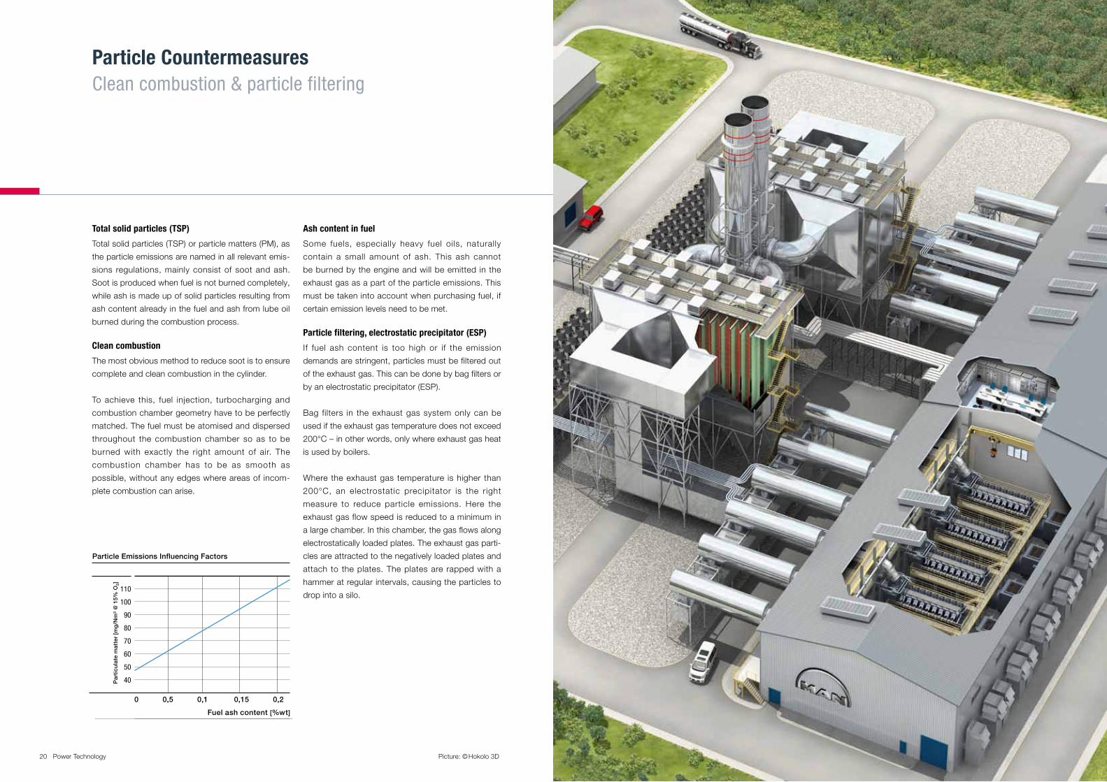
Par
ticu
late
mat
ter
[mg
/Nm
3 @
15%
O2]
0 0,5 0,1 0,15 0,2
Fuel ash content [%wt]
Particle Emissions Influencing Factors
110
100
90
80
70
60
50
40
Total solid particles (TSP)
Total solid particles (TSP) or particle matters (PM), as
the particle emissions are named in all relevant emis-
sions regulations, mainly consist of soot and ash.
Soot is produced when fuel is not burned completely,
while ash is made up of solid particles resulting from
ash content already in the fuel and ash from lube oil
burned during the combustion process.
Clean combustion
The most obvious method to reduce soot is to ensure
complete and clean combustion in the cylinder.
To achieve this, fuel injection, turbocharging and
combustion chamber geometry have to be perfectly
matched. The fuel must be atomised and dispersed
throughout the combustion chamber so as to be
burned with exactly the right amount of air. The
combustion chamber has to be as smooth as
possible, without any edges where areas of incom-
plete combustion can arise.
Ash content in fuel
Some fuels, especially heavy fuel oils, naturally
contain a small amount of ash. This ash cannot
be burned by the engine and will be emitted in the
exhaust gas as a part of the particle emissions. This
must be taken into account when purchasing fuel, if
certain emission levels need to be met.
Particle filtering, electrostatic precipitator (ESP)
If fuel ash content is too high or if the emission
demands are stringent, particles must be filtered out
of the exhaust gas. This can be done by bag filters or
by an electrostatic precipitator (ESP).
Bag filters in the exhaust gas system only can be
used if the exhaust gas temperature does not exceed
200°C – in other words, only where exhaust gas heat
is used by boilers.
Where the exhaust gas temperature is higher than
200°C, an electrostatic precipitator is the right
measure to reduce particle emissions. Here the
exhaust gas flow speed is reduced to a minimum in
a large chamber. In this chamber, the gas flows along
electrostatically loaded plates. The exhaust gas parti-
cles are attracted to the negatively loaded plates and
attach to the plates. The plates are rapped with a
hammer at regular intervals, causing the particles to
drop into a silo.
Particle CountermeasuresClean combustion & particle filtering

22 Power Technology – For a greener planet 23Power Technology – For a greener planet
Engine Emissions and their Effects
NOx
NOx is the collective term for the two oxides of
nitrogen:
Nitric oxide (NO) Nitrogen dioxide (NO2)
Nitrogen (N2) makes up some 80% of air and is virtu-
ally inert at normal temperatures and pressures.
However, it will react with the oxygen (O2) in the intake
air of combustion engines, at the temperatures and
pressures prevailing in the combustion chamber.
NOx is instrumental in the formation of low-level ozone,
acid rain, and the deposition of nitrates, which act as
fertilisers, disturbing the natural ecological balance
by over-fertilising the land and sea. Acid rain is the
result of NOx combining with water in the atmos-
phere to form nitric and nitrous acids. It is consid-
ered extremely harmful to both animal and plant life. In
particular, it is held responsible for damage to forests
and other vegetation.
SOx
SOx is the collective term for oxides of sulphur. During
combustion, the sulphur (S) present in diesel fuels is
oxidised to form sulphur dioxide (SO2) and sulphur
trioxide (SO3). As with NOx, the oxides combine with
water in the atmosphere to form sulphurous and
sulphuric acids, which are major constituents of acid
rain. As well as its role in the formation of acid rain,
both SO2 and SO3 in diesel engine exhaust gases
combine with ammonia in selective catalytic reduc-
tion systems. The resulting ammonium sulphate forms
deposits on the catalyst cores (SCR) and greatly
impairs their effectiveness in reducing NOx.
CO2
During combustion in diesel and gas engines, the
overwhelming majority of the carbon (C) constituent
of hydrocarbon fuels is oxidised to carbon dioxide
(CO2) while only traces of carbon monoxide (CO) are
formed.
Though not poisonous, CO2 does not support life and
can suffocate at high concentrations. More impor-
tantly, it is the most common “greenhouse gas”,
capable of absorbing infra-red radiation and therefore
a major source of global climate change.
While there are currently no mandatory regulations
affecting CO2, these are expected, and are almost
certain to include large engines. However, under inter-
national agreements such as the Kyoto Protocol and
the European Union’s accord on greenhouse gases,
many governments are committed to substantial
reductions in total emissions of CO2 and other gases
held responsible for global warming (e.g. methane).
On the incentive side, many countries reward the
generation of electric power using renewable fuels,
and/or operate carbon-trading schemes. In the latter,
organisations employing CO2 neutral technologies
acquire credits which are sold to organisations with a
positive CO2 balance.

MAN Diesel & Turbo 86224 Augsburg, Germany Phone +49 821 322-3897Fax +49 821 [email protected]
All data provided in this document is non-binding. This data serves informational
purposes only and is especially not guaranteed in any way. Depending on the
subsequent specific individual projects, the relevant data may be subject to
changes and will be assessed and determined individually for each project. This
will depend on the particular characteristics of each individual project, especially
specific site and operational conditions. Copyright © MAN Diesel & Turbo.
D2366457EN-N2 Printed in Germany GMC-AUG-07122
MAN Diesel & Turbo – a member of the MAN Group