power system dynamic state estimation based protection and
TRANSCRIPT

1
Power System Dynamic State Estimation Based Protection and Fault Location
Rui Fan
Pacific Northwest National LaboratoryGeorgia Institute of Technology

2
System Events
Fault Conditions
Normal Transients
Relay ActionsTrip Dependable
Secure
Mis-operation
No-Trip
No-Trip
Trip

3
Source: NERC, Misoperation, https://www.eiseverywhere.com/file_uploads/fa776bec5502184fa6cb828ea07ff129_BauerHORSpresentation.pdf

4
Root causes:– Incorrect setting– Incorrect coordination– Incapability
0 0.02 0.04 0.06 0.08 0.1
Seconds
-400
-200
0
200
400
Amp
Trip
Undependable
Unsecure
Load change
High impedance fault
Solution: Dynamic State Estimation (DSE) Based Protection Scheme (a.k.a. Settingless Protection)

5
DSE-Based Protection Scheme--inspired from Differential protection
Analytics: Dynamic State Estimation (systematic way to determine observance of physical laws)
6
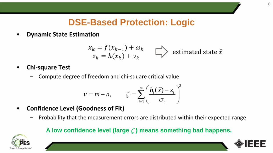
DSE-Based Protection: Logic• Dynamic State Estimation
• Chi-square Test– Compute degree of freedom and chi-square critical value
• Confidence Level (Goodness of Fit)– Probability that the measurement errors are distributed within their expected range
𝑥𝑥𝑘𝑘 = 𝑓𝑓(𝑥𝑥𝑘𝑘−1) + 𝜔𝜔𝑘𝑘𝑧𝑧𝑘𝑘 = ℎ(𝑥𝑥𝑘𝑘) + 𝜈𝜈𝑘𝑘
estimated state 𝑥𝑥
2
1
ˆ( ),m
i i
i i
h x zm nν ζσ=
−= − =
∑
A low confidence level (large ζ ) means something bad happens.

DSE-basedProtection
7
DSE-Based Protection: HIL Test

8
DSE-Based Protection: ExampleEvent: Transformer Fault
• 14.4/2.2kV, 1000 kVA single-phase saturable-core transformer
• A 5% turn-ground fault near neutral terminal of the transformer at 3.5 s
List of Measurements:
• 𝑉𝑉1,𝑉𝑉2: voltages at two sides
• 𝐼𝐼1, 𝐼𝐼2: currents at two sides

9
Traditional Differential ProtectionSettings:• Operating Current:
• Restraining Current:
• Differential Ratio:
𝐼𝐼𝑜𝑜𝑜𝑜 = 𝑰𝑰𝑠𝑠1 + 𝑘𝑘𝑰𝑰𝑠𝑠2
𝐼𝐼𝑟𝑟𝑟𝑟𝑠𝑠 = 𝑰𝑰𝑠𝑠1
𝑅𝑅 = 𝐼𝐼𝑜𝑜𝑜𝑜/𝐼𝐼𝑟𝑟𝑟𝑟𝑠𝑠
Differential Relay Will Trip If:• Operating Current > 5 A, AND
• Differential Ratio > 15%

10
Results: Differential Protection
<5 A
<15%
Traditional Differential Protection Relay MISSES the Fault
11
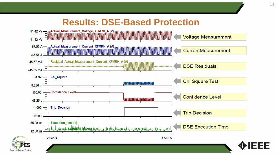
Results: DSE-Based Protection

12
DSE-Based Protection: a Generic Protection Scheme
“One of the most promising techniques to solve the protective challenges in next 10 years”― 2018 report “Future State of Protective Relaying” to
DOE

13
Conventional Fault Location• Minimize labor and outage time.• Conventional methods:
– Single-ended algorithms
– Dual-ended algorithms
• Shortages:– Accuracy is affected by 𝑅𝑅𝐹𝐹 and line coupling– Require 3~4 cycles of measurements after the fault
Im( / )Im( )
S S
L
V ImZ
=
( )S R L R
L S R
V V Z ImZ I I− +
=+

14
DSE-Based Fault LocationModify original DSE model to include the fault location as a variable 𝒎𝒎
Left Side Right Side
𝑦𝑦𝑘𝑘 = 𝑓𝑓(𝑦𝑦𝑘𝑘−1,𝑢𝑢𝑘𝑘−1) + 𝜔𝜔𝑘𝑘𝑧𝑧𝑘𝑘 = ℎ(𝑦𝑦𝑘𝑘 ,𝑢𝑢𝑘𝑘) + 𝜈𝜈𝑘𝑘
where 𝑦𝑦 = [𝑥𝑥,𝑚𝑚]𝑇𝑇
15
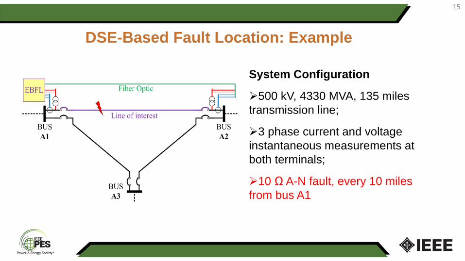
DSE-Based Fault Location: Example
System Configuration
500 kV, 4330 MVA, 135 miles transmission line;
3 phase current and voltage instantaneous measurements at both terminals;
10 Ω A-N fault, every 10 milesfrom bus A1
16
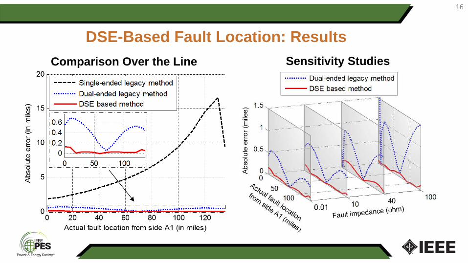
DSE-Based Fault Location: ResultsComparison Over the Line Sensitivity Studies

17
Conclusions
• DSE-based protection can enhance relays dependability, security, and action speed; DSE-based fault location can accurately pinpoint the fault with less than one-cycle data
• The technology exists. We need to continue developments to bring these approaches to a practical level.
I would like to thank my colleagues at,PNNL: Renke Huang, Shaobu Wang, Tom McDermott, Zhenyu HuangGaTech: Sakis Meliopoulos, Yu Liu, Liangyi Sun, George Cokkinides , Zhenyu Tan