position control system of hydraulic cylinderposition control system of hydraulic cylinder based on...
TRANSCRIPT

Journal of Engineering and Development, Vol. 12, No. 3, September (2008) ISSN 1813-7822
25
Position Control System of Hydraulic Cylinder Based on Microcontroller
Abstract
Recently, the industrial applications using an electro-hydraulic system have been
widely used. Since these are necessary and more ambitious specifications with respect to
positioning accuracy, rapid motion and for generating large forces. Position control system
is one of the applications in the area of the electro-hydraulic systems.
In this work, a single ended hydraulic cylinder with limit position sensor was
employed. It was proposed to develop a position control system that incorporates features of
a microcontroller interfacing with position sensors and detecting the position of the
hydraulic cylinder rod.
Microcontrollers are ideal for embedded control applications since a self - contained
control system may be constructed with just a few components. Developing such a system
required to build a software part running on the microcontroller as well as a hardware part
consisting of mechanical and electronic components. An electro-hydraulic system based on
the proportional valve technology was employed. The heart of this system is an electrically
adjustable proportional directional control valve linked to the embedded controller MCS51
via Proportional, Integral and Derivative (PID) controller .The simulation for the system
was carried out by Simulink/Matlab model and the results show that the controller of the
system can be easily tuned by software and adjusted to meet the requirements for the
position control of the hydraulic shafts. Very high accuracy was achieved where error
could be due to backlash of the hydraulic shaft and the resolution of converting analogue
signals to binary.
Asst. Lect. Munaf F. Bader
Mechanical Engineering Department, College of Engineering
Al-Mustansiriya University, Baghdad, Iraq
Journal of Engineering and Development, Vol. 12, No. 3, September (2008) ISSN 1813-7822
26
ةـــــــالصـالخلكهروهيدروليكية ضرورية ومالئمة من لتطبيقات ألصناعية ألتي تستخدم أألنظمة أاأصبحت ،في أآلونة األخيرة
سرعة أألداء والحصول على قوة كبيرة. إن نظام السيطرة على طول الشوط لألسطوانة الهيدروليكية ، ستجابةاإلناحية دقة هو أحد مجاالت ألتطبيق لألنظمة ألكهروهيدروليكية.
السيطرة على طول الشوط جة مشكلة عدمتكون األسطوانة الهيدروليكية ذات نهاية واحدة ولمعال، لبحثافي هذا لدقيق وبوجود متحسسات توقف المسيطر نظام توقيف ذاتي مدمج مع ميزات ا ألمر تطويراللمكبس الهيدروليكي تطلب
لتي تتحسس طول الشوط للمكبس.ان إلمكونات. ابناء نظام سيطرة وبعدد قليل من إلمكانية لمختزلة نظرا الدقيق مثالي للتطبيقات المسيطر ايعتبر
لتحسين لدقيق إضافة إلى بناء منظومة كهروميكانيكية.المسيطر برنامج يدار من قبل ا تطوير مثل هكذا نظام يحتاج إلىالتناسبية س تقنية ألصمامات كي، تم إستخدام نظام هيدروليكي مستند على أسانظام السيطرة على توقف المكبس الهيدرولي
لمعالج المسيطر عليه كهربائيا والمربوط مع اتجاهي اإللتناسبي الصمام النظام هو ا لرئيسي في هذاالجزء حيث أن ا لمنظومة تم إستخدام برنامج اولمحاكاة PIDعن طريق مسيطر من نوع MCS51لدقيقا
MATLAB/SIMULINK يمكن تعييره وتضبيطه لمسيطران هذا إلتي أظهرت النتائج الحصول على الغرضلهيدروليكي وإمكانية تحقيق دقة عالية مع المكبس السيطرة على موقع حركة التقاء مع متطلبات اإلمج ولبرنااباستخدام هذا
لموجودة عندما الدقة اومدى الهيدروليكيلمكبس افي Backlashلخطأ قد يحدث نتيجة لحصول ا نإعتبار اإلألخذ بنظر ا
لرقمي.التحويل الكمي إلى نوع رقمي في دائرة النوع اإلشارة ذات ايتم تحويل
1. Introduction
Electro-hydraulic actuators are widely used in industrial applications. It can generate
very high forces, exhibit rapid responses and have a high power to weight ratio compared
with their electrical counterparts [1]
. Many industrial applications in both military and civilian
fields such as drilling platforms, plastic injection machines, cranes and fire vehicles need
position control system. The accuracy of position system determines the kind of hydraulic
module, which is used, and according to the required accuracy the hydraulic control valves
can be selected.
The general classification of the hydraulic valves may be divided into conventional
control valves and proportional control valves. The conventional models become
inappropriate and have limited scope if one requires a precise and fast performance [2]
.
So for, fast response, high accuracy, an automatic position control module employing an
electro-hydraulic subsystem depending on hydraulic valve technology and linked to the
embedded controller is one of the best solutions. The basic part of this technology is the
proportional directional control valves, with its solenoids, provide the ideal interface for
electronic controls [3]
. The proportional valve controls the direction of movement and the
speed of the hydraulic cylinders the output hydraulic flow from it is proportional to the
electrical input signal to the valve solenoid [4]
.
Microcontroller is an entire computer manufactured on a single chip. The I/O and
memory subsystems contained in microcontroller specializes the device so that it can be
interfaced with hardware and control functions of the applications. Due to the low cost and
ease of integration within an application microcontrollers are used whenever possible to
reduce the chip count of a piece of electronic components [5]
.
The second section explains the design procedures of the position control system in
addition to the description of the platform structure and the electro-hydraulic subsystem. A
detailed description of the experimental work of the position control system is presented in
Journal of Engineering and Development, Vol. 12, No. 3, September (2008) ISSN 1813-7822
27
the third section, besides that the simulation of the electro-hydraulic system is presented in the
fourth section followed by the conclusions.
2. Position Control System
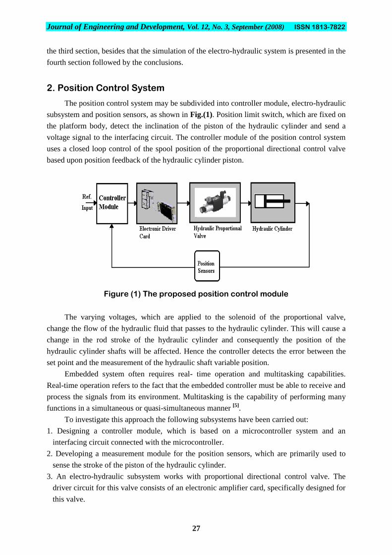
The position control system may be subdivided into controller module, electro-hydraulic
subsystem and position sensors, as shown in Fig.(1). Position limit switch, which are fixed on
the platform body, detect the inclination of the piston of the hydraulic cylinder and send a
voltage signal to the interfacing circuit. The controller module of the position control system
uses a closed loop control of the spool position of the proportional directional control valve
based upon position feedback of the hydraulic cylinder piston.
Figure (1) The proposed position control module
The varying voltages, which are applied to the solenoid of the proportional valve,
change the flow of the hydraulic fluid that passes to the hydraulic cylinder. This will cause a
change in the rod stroke of the hydraulic cylinder and consequently the position of the
hydraulic cylinder shafts will be affected. Hence the controller detects the error between the
set point and the measurement of the hydraulic shaft variable position.
Embedded system often requires real- time operation and multitasking capabilities.
Real-time operation refers to the fact that the embedded controller must be able to receive and
process the signals from its environment. Multitasking is the capability of performing many
functions in a simultaneous or quasi-simultaneous manner [5]
.
To investigate this approach the following subsystems have been carried out:
1. Designing a controller module, which is based on a microcontroller system and an
interfacing circuit connected with the microcontroller.
2. Developing a measurement module for the position sensors, which are primarily used to
sense the stroke of the piston of the hydraulic cylinder.
3. An electro-hydraulic subsystem works with proportional directional control valve. The
driver circuit for this valve consists of an electronic amplifier card, specifically designed for
this valve.

Journal of Engineering and Development, Vol. 12, No. 3, September (2008) ISSN 1813-7822
28
4. Hydraulic cylinder fixed on the frame as shown in Fig.(2) to actuate the load, left and right,
until the required position is achieved.
Figure (2) The position control system
3. Design of the Position Control System
The electro-hydraulic module of the position control system contains hydraulic cylinder
and four ways, two electrical solenoid hydraulic proportional valves with their electronic
cards representing the linking element between the controller module and solenoids of the
valve. Each valve controls the flow and direction of the hydraulic fluid that passes through it
towards the hydraulic cylinder leading to move the cylinder left and right with acceptable
speed.
The employed hydraulic system as shown in Fig.(3) works with proportional valve
technology, and the general items in this hydraulic subsystem are:
1. The power unit.
2. The hydraulic control unit.
3. Hydraulic cylinder.
4. Accessories.
5. Pipes and hoses.

Journal of Engineering and Development, Vol. 12, No. 3, September (2008) ISSN 1813-7822
29
Hydraulic Tank
Symbols for equipment
Figure (3) The diagram of hydraulic subsystem and hydraulic actuators
The hydraulic control unit consists of proportional directional control valves and their
associated electronic amplifier card. Hydraulic cylinder of (50 mm) bore diameter, (28 mm)
rod diameter and (250 mm) stroke is used to actuate the load left and right. The power unit of
the hydraulic system consists of hydraulic pump, non-return valves, filter, and hydraulic tank.
According to the signal coming from the electrical card, the control spool of this valve is
shifted either to the right or to the left depending on the polarity of incoming voltage signal
positive or negative, the stroke of the spool is therefore proportional to the electrical signal
and it is used to control opening and closing function [6]
as shown in Fig.(4).

Journal of Engineering and Development, Vol. 12, No. 3, September (2008) ISSN 1813-7822
30
Figure (4) The hydraulic actuators employed in position control system
The voltage signals of the position sensors, which are received by the microcontroller,
are proportional to the position of the hydraulic cylinder shaft and accordingly signals are
generated and applied to a driver circuit that controls the hydraulic valve. As the signal
increases the stroke will increase and the flow of hydraulic oil will increase causing greater
volumetric flow [3]
. The basic components of the valve are shown in Fig.(5).
Figure (5) The stroke-controlled proportional solenoid [1]
The embedded controller module that was employed and prototyped position control
system consists of the microcontroller MC51 besides interfacing circuits (ADC and DAC) as
shown in Fig.(6). The MC51 reads the voltage values and compares them with the set point of
initial position that is stored in it.

Journal of Engineering and Development, Vol. 12, No. 3, September (2008) ISSN 1813-7822
31
Reference input
Controller Module
Microcontroller
89C51
Digital to Analogue
Converter
Analogueto Digital
Converter
Electronic Card of
Proportional Valve
Hydraulic CylinderSolenoid of the
Proportional valve
The Proportional
Hydraulic Valve
Position Sensors
Figure (6) The block diagram of position control system
In order to control the position setting, the output voltage of the microcontroller is
converted from digital to analogue type by the DAC circuit and the proportional valve
solenoid will be actuated via the electronic amplifier card of this valve.
Only three external control lines were required to control the analogue to digital
converter circuit (AD574A) as shown in Fig.(7). One line was needed to select either 8-bit or
12-bit conversion. A second line was connected to the R/C line to control whether a
conversion or output data should occur while the third line was connected to the chip-enable
line to activate the wanted functions.
Figure (7) The connections and timing diagram of AD 574A [7]
The controller module of the position system uses the following power supplies
(1) +5V supply the microcontroller 89C51 and its support circuit.
(2) ±15V power supplies the interfacing circuit.
(3) +24V power, supplies the driver card of hydraulic proportional valve
The output pins of the digital to analogue circuit (DAC) are hard wired connected to an
op-amp circuitry in order to tune the required gain and the result analogue output voltage
signal from this circuit would be supplied to the electronic driver card of the proportional
valve as shown in Fig.(8).

Journal of Engineering and Development, Vol. 12, No. 3, September (2008) ISSN 1813-7822
32
V-
3
V+
13
Iout4
Iout2
msbB15
B26
Vrf(-)15
B3 7
B4 8
Vrf(+)14
B5 9
B6 10
Vlc1
B7 11
lsbB8 12
COMP16
U6
DAC0800
3
26
1 5
74
U4741
C17
10nf
-12
R14
5k R15
5k
+12
-12
C16
100nf
R16
5k
R17 5k
I/O
To Electronic
Card of Proportional
Valve
Figure (8) The connection diagram of the digital to analogue converter circuit
The 89C51microcontroller reads signals or data from its ports and sends the results as an
output signals .All four ports P0, P1, P2 and P3 are bi- directional, as shown in Fig.(9) Pin 31
(/EA) of the MC 89C51 is a control pin, If /EA is logic „1‟, the device looks for its program in
internal EPROM. If /EA is logic „0‟, the device looks for its program in External EPROM [8]
.
EA/VP31
X119
X218
RESET9
RD17
WR16
INT012
INT113
T014
T115
P101
P112
P123
P134
P145
P156
P167
P178
P0039
P0138
P0237
P0336
P0435
P0534
P0633
P0732
P2021
P2122
P2223
P2324
P2425
P2526
P2627
P2728
PSEN29
ALE/P30
TXD11
RXD10
U5
8951
CT1CRYSTAL
R12
1K
C15
33PF
C14
33PF
VCC
C1322uF
+5
S1
RESET
VCC
D1-2D1-3D1-12D1-13D2-2D2-3D2-12D2-13
DB0DB1DB2DB3DB4DB5DB6
DB8DB9DB10msb11D3-2D3-3D3-12D3-13
GANG RESISTER 4.7K
P07
P06
P00
P01
P02
P03
P04
P05
R13
Figure (9) The microcontroller 89C51 subsystem
Journal of Engineering and Development, Vol. 12, No. 3, September (2008) ISSN 1813-7822
33
The microcontroller selects one of the position sensors of the hydraulic cylinder (either
left or right) and sends a start signal to the A/D chip to begin converting the analogue voltage
signals of the position sensor. When the conversion is completed the microcontroller stores
the digital value from the A/D chip and compares the read data with the set point of the
position.
The D/A converter interfaces with electronic amplifier card of the proportional valve to
actuate the hydraulic cylinder until the required position is being achieved, After the hydraulic
cylinder is being in position the microcontroller selects the next sensor and commands the
A/D chip to begin the conversion. There are several types of sensors could be used to achieve
the leveling such as Potentiometers, Capacitance sensors, Inductive distance measuring
sensors and others [9]
. The software design consists of three parts. The first part controls the
A/D converter chip and reads the data from it, the second one compares the read data, and the
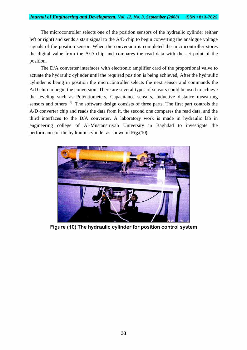
third interfaces to the D/A converter. A laboratory work is made in hydraulic lab in
engineering college of Al-Mustansiriyah University in Baghdad to investigate the
performance of the hydraulic cylinder as shown in Fig.(10).
Figure (10) The hydraulic cylinder for position control system

Journal of Engineering and Development, Vol. 12, No. 3, September (2008) ISSN 1813-7822
34
4. Simulation Process
Simulation has been performed to investigate the performance of the electro-hydraulic
subsystem for the position control system. The actuators, valves and cylinders were modeled
using their parameters provided by the manufacturer. PID controller for the valve was
included in the model and the transfer function was generated for that. The transducer gives a
feedback signal to the PID controller, which is inserted in the forward path.
This was accomplished using SIMULINK/MATLAB, which prompts the user to modify
the PID and the actuators parameters, and then the results are plotted in MATLAB. The
simulation includes two steps, the first one is a MATLAB file that has the model of the
transfer function and the second one is a SIMULINK graphics model that simulates the
system step response.
In controlling an electro-hydraulic proportional valve the PID system was used to
control the solenoid of the hydraulic valve in order to control the linear position of the valve
spool tending to govern the flow rate of the hydraulic fluid, which passes the valve towards
the hydraulic cylinder so that the position of the cylinder rod can be proportionally adjusted.
x(t) + e(t) V y(t)
-
x - Desired Position. y - Actual Position.
e - Error = Desired Position (x) –Actual (y). V- Solenoid Valve Voltage
PID
Controller
Proportional Valve
Transfer Function
Figure (11) The block diagram of PID control system
As it has been shown in Fig.(11), the PID output becomes a voltage applied to the
solenoid of the hydraulic valve and the feedback signal is a linear position measured by an
inductive positional transducer that is linked with the spool of the valve. The classic three
terms (Proportional + Integral + Derivative) control algorithm uses three components: error,
time integral of error, and time derivative of error [10]
. The PID controller is defined by the
following relationship between the controller input e (t) and the controller output v (t) that is
applied to the proportional valve.
dt
)t(deKd)(d)(eKi)t(Kpe)t(v
t
……………………………………….. (1)
where:
Kp, Ki and Kd: are proportional, integral and derivative constants.
e(t): error signal between reference input and output voltage signal.
v(t): output voltage signal.
Journal of Engineering and Development, Vol. 12, No. 3, September (2008) ISSN 1813-7822
35
Taking the Laplace transform of equation (1) gives the transfer function:
s
i
)s(
SKd
s
KKp
E
V ………………………………………………………... (2)
The PID controller gains can be adjusted by changing the data and observing the
behavior of the system to stabilize the control process to optimal behavior. The following
MATLAB codes are used to simulate this system.
Kp=7;Ki=9;Kd=3;
num=[Kd, Kp, Ki]; den=[1, 1+Kd, 1+Kp, Ki];
numb=[2,5,5]; denb=[1,3,6,5]; numc=[2,2,1]; denc=[1,3,3,1];
numd=[1,5,1]; dend=[1,2,6,1]; numa=[1]; dena=[1];t=0:01:20;
syso=tf (num, den); sysa=tf (numa, dena); sysb=tf (numb, denb);
sysc=tf (numc, denc); sysd=tf (numd, dend);
y0=step (syso, t); y1=step (sysa, t); y2=step (sysb, t); y3=step (sysc, t);
y4=step (sysd, t); plot (t, [y4 y3 y2 y1 y0]); grid
xlabel („time (sec)'); ylabel („y (t)');title ('Proportional Valve Response');
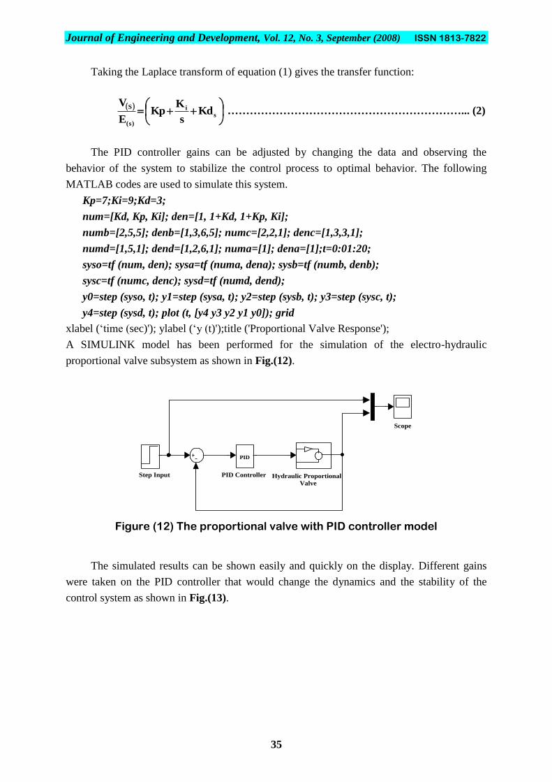
A SIMULINK model has been performed for the simulation of the electro-hydraulic
proportional valve subsystem as shown in Fig.(12).
Figure (12) The proportional valve with PID controller model
The simulated results can be shown easily and quickly on the display. Different gains
were taken on the PID controller that would change the dynamics and the stability of the
control system as shown in Fig.(13).
Scope
Step Input
PID
PID Controller Hydraulic Proportional
Valve

Journal of Engineering and Development, Vol. 12, No. 3, September (2008) ISSN 1813-7822
36
Figure (13) The proportional valve response
In order to simulate all blocks of the hydraulic subsystem, this model consists of the PID
controller, proportional valve and the hydraulic cylinder and a system under consideration is
shown in Fig.(14).
Scope3
Hydraulic
Cylinder Proportional
Valve
Step
Input
Scope2
Scope1
PID
PID
Controller
Figure (14) The proportional valve and hydraulic cylinder model
Different characteristics of the hydraulic valve and cylinder response such as rise time,
steady-state error and peak overshoot are controlled by the selection of the three gains of the
PID controller. The PID is tuned to give fast and smooth responses to a step input signal. The
result of the simulation may be plotted as shown in Fig.(15).
Figure (15) The valve and cylinder response
Journal of Engineering and Development, Vol. 12, No. 3, September (2008) ISSN 1813-7822
37
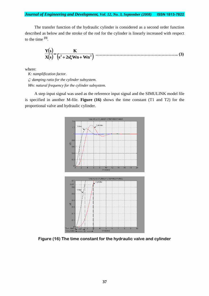
The transfer function of the hydraulic cylinder is considered as a second order function
described as below and the stroke of the rod for the cylinder is linearly increased with respect
to the time [3]
.
22
WnWns2s
K
sX
sY
………………………………………………….. (3)
where: K: namplification factor.
damping ratio for the cylinder subsystem.
Wn: natural frequency for the cylinder subsystem.
A step input signal was used as the reference input signal and the SIMULINK model file
is specified in another M-file. Figure (16) shows the time constant (T1 and T2) for the
proportional valve and hydraulic cylinder.
Figure (16) The time constant for the hydraulic valve and cylinder
Journal of Engineering and Development, Vol. 12, No. 3, September (2008) ISSN 1813-7822
38
5. Conclusions
1. This work is based on the design and implementation of a position control system of the
hydraulic cylinder system that could be easily interfaced with a microcontroller module.
The design centers around building an electronic controller module involving
microcontroller and other peripherals interfaced with position sensor and a hydraulic
proportional directional control valve,
2. Hydraulic proportional valve is chosen in this work to improve the performance of an
electro-hydraulic system used in the position control module.
3. The design of the controller module for the position control system requires involving both
hardware and software considerations. Investigation has shown the ability of implementing
the controller module based on microcontroller for limiting the position of the hydraulic
cylinder interfaced with “PID controller”.
4. Simulation has been performed to investigate the performance of the electro-hydraulic
subsystem that was used in position control system gave good results. Even though not
much experimental work has been finished, a good start has been made and initial tests have
been promising.
5. The results show that the controller of the system can be easily tuned by software and
adjusted to meet the requirements for the position control of the hydraulic shafts. Very high
accuracy was achieved where error could be due to backlash of the hydraulic shaft and the
resolution of converting analogue signals to binary.
Journal of Engineering and Development, Vol. 12, No. 3, September (2008) ISSN 1813-7822
39
6. References
1. M. R., Sirouspour, and S. E., Salcudean, “On the Nonlinear Control of
Hydraulic Servo-systems”, Department of Electrical and Computer Engineering,
British Columbia University, 1996, Available at E-mail: [email protected],
2. P. J., Costa Branco, and J. A., Dente, “Design of an Electro-Hydraulic System
using Neuro-Fuzzy Techniques”, Mechatronics Laboratory, Department of
Electrical and Computer Engineering, Lisbon, Portugal, 2000.
3. Rexroth Staff, “Hydraulic Trainer-Proportional and Servo Valve Technology”,
Volume 2, Manesman Rexroth, 1986.
4. Rexroth Staff, “Hydraulic Trainer: Instruction and Information on Oil
Hydraulics”, Volume 1, Manesman Rexroth, 1981
5. Y., Sencer, “Programming and Interfacing the 8051 Microcontroller”, Rigel
Corporation, 1995.
6. Proportional Valve Technology, from CCI Valve Technology, Available at
http://www.ccivalve.com
7. Complete 12-Bit A/D Converter AD574, Available at http://www.analog.com/
product selection /pdf/ad574a.pdf, Analog Devices.
8. T. W., Schultz, “C and the 8051: Hardware Modular, Programming, and
Multitasking”, Volume1, Prentice Hall Inc, 1998.
9. Alexander H. Slocum, Precision Machine Design, Topic 8, Sensor systems, 1994,
available at http://www.yahoo.com.
10. E. A., Parr, “Industrial Control Handbook”, Volume 2, BSP Professional Books,
1987.