genesis digital hydraulic over-speed control system€¦ · genesis digital hydraulic over-speed...
TRANSCRIPT

bypassed to tank (as in the case of pressure compensated valves that bleed a given amount of fl ow continuously throughout the entire work cycle), to now be directed to the work circuit providing full power to the hydraulic system. This can translate to over 3.5 horsepower loss to tank for traditional compensated valves verses Permco's bleed valve.
Control of the system when used in an unloader system setup is accomplished through the use of one (1) on/off solenoid valve and one (1) speed sensor. The closed loop input/output digital controller is used to open and close the solenoid in response to varying speeds. A microprocessor converts the speed sensor output into RPM's and sends a signal to the one (1) on/off solenoid to change its output based on user selected set points. The on/off solenoid is a 2-way normally open hydraulic cartridge valve which controls the opening and closing of the unloader tank port. When activated 100% of the pump flow is diverted back to tank at very little pressure.
Genesis Digital HydraulicOver-Speed Control System
Permco offers a closed loop digital input/output hydraulic over-speed control and speed sensor that is used in conjunction with Permco's VERSA-PAK series refuse pumps. In refuse applications it is usually required that the vehicle's hydraulic system be able to operate while in motion. This creates a problem in that while the pump delivers the required fl ow at or near idle RPM's, the operator would have the ability to substantially over-speed the hydraulic system (and in turn the mechanics of the truck) while operating the vehicle at speeds associated with moving (roading) the vehicle. Permco's Genesis system over-speed control eliminates this possibility by shutting the pump inlet fl ow off (dry valve system) or unloading discharge fl ow to tank (unloader system) when a predetermined over-speed setting is reached, protecting the hydraulic system, the mechanics of the truck and the pump.
Control of the system when used in a dry valve system setup is accomplished through the use of two (2) on/off solenoid valves and one (1) speed sensor. The closed loop input/output digital controller is used to open and close these valves in response to varying speeds. A microprocessor converts the signal from the speed sensor into RPM's and sends a signal to the two (2) on/off solenoid valves to change their output based on user selected set points. One (1) of the valves is an electric/air, which controls the opening and closing of the dry valve; the second valve is a 2-way normally open hydraulic cartridge valve which controls the opening and closing of the “bleed valve” tank port. The solenoid bleed valve gives the dry valve lubrication flow a direct, unrestricted path to the hydraulic tank. Unlike other manufacturer's bleed valves that provide a similar function, the Permco design is the only one available that is integral to the pump itself and provides a positive closure (shutoff) when the pump is told to do work. This design allows all flow that would have

The speed sensor which threads directly into the gear housing (provided by Permco) is an active Hall Effect type, each time a gear tooth passes in front of the sensor the output changes state generating a steady pulse train of frequency proportional to target speed, this pulse train of frequency is read by the digital controllers microprocessor and converted to RPM's, when the selected set points RPM's are reached a signal is sent to the corresponding solenoids to open or close. This speed sensor has full pressure capabilities unlike other units on the market. This minimizes any problems should it see pressure spikes from the system.
Reliability has been addressed on several levels.
1. First of all, Permco warrants their pumps and motors for two full years. Dependability is a very high priority for Permco. We strive to make it right the fi rst time.
Efficiency is another aspect about which Permco is concerned. With the hundreds of thousands refuse vehicles operating daily, each vehicle must be running at capacity and at as low of a maintenance cost as possible. With this new Permco Genesis system, we have documentation showing increased productivity and fuel savings over the common unloader systems. Because we are controlling the hydraulic system, we can give the operator hydraulic fl ow and pressure at the appropriate time and at the appropriate rate. By closely controlling the hydraulic system, issues such as heat and fl ow saturation of the system are virtually eliminated.Gear pumps are an effi cient and cost effective means to supply the required gallons per minute/pressure for this industry’s hydraulic requirements. Other more expensive pumps are not as tolerant of conditions that exist in the refuse market. Replacement and downtimes are minimized because of reliability, availability, and simplicity of design.
The controller interfaces with a PC using RS232 communications for confi guration of the module. Windows HyperTerminal can be used to set or change the RPM ranges from their default settings; unit is shipped with complete wiring harness set.
solenoids controlling the air to the dry valves go into the dry mode, the corresponding electric/hydraulic solenoids open, ensuring a direct path for the fluid back to tank.
Permco1500 Frost Rd.P. O. Box 2068Streetsboro, OH 44241
Phone 330-626-2801 Fax 330-626-2805
e-mail [email protected]
that eliminate the possibility of contamination getting into the front outboard bearing. This front outboard bearing seal extends the life of the bearing, but, at the same time, we also know that contamination getting to that bearing often shortens the life of the pump. Rather than eliminating the outboard bearing as other suppliers have done, we leave the bearing in to maintain stability but we protect it to eliminate premature failure.
4. Running hot and cavitation are often associated with dry valve systems. We have eliminated these by establishing a positive bleed valve system eliminating the possibility of pressure on the discharge side of the pump in the dry mode. When the electric/air
2. 100% of Permco pumps are factory tested to eliminate even the possibility of an occasional problem.
3. Permco uses front outboard bearing seals
The digital controller is a compact IP67 rated package with plug-in connections for remote mounting. Power supply is 12 or 24 VDC with reverse polarity, transient surge and over-current protection provided.
Both the dry valve system and the unloader system can incorporate Permco's VERSA-PAK pressure compensated fl ow control valve, this allows a preset amount of flow to the hydraulic system with the excess fl ow being returned to the suction side (dry valve system) or returned to tank (unloader system); this function protects the system's main relief valve from being fl ooded so it can better accomplish its function of controlling system pressure and reduces the possibility of cavitating the pump at high RPM's (dry valve system). Because the system never exceeds the correct fl ow, it doesn't have the consequential pressure spikes resulting in cylinder and component failure.
You have a choice. Make it PERMCO.

The Genesis Fuel Saving Systems are tandem (two pumping sections) P7600 dry valve pumps. The displacement of the two sections is dependant upon the desired controlled engine speed and the necessary GPM’s required for proper cycle times. Generally, for a commercial front loader, for instance, the requirements are in the 45-60 GPM range. With a front or rear loader, it is usually required that the vehicle be able to operate while in motion. This creates a problem in that while delivering the required GPM’s at or near idle RPM’s, the operator would have the ability to substantially over-speed the hydraulic system (and in turn the mechanics of the truck) while operating the vehicle at RPM’s associated with moving (roading) the vehicle. Permco’s Genesis system essentially eliminates this possibility by controlling both sections of the pumping group independently.
Both sections of the pump are controlled independently by an electronic speed sensor with different speed settings for each pumping section. At idle speed (600-850 RPM’s) both pumping sections are in the wet mode, which means that maximum fl uid is available to the hydraulic system. At any time the engine RPM is increased above the 1st speed switch setting (approximately 650 RPM’s) the front pumping section of the pump goes into the dry mode (no fl uid output). The back section of the pump is still operational (wet mode) until the engine reaches the 2nd speed switch setting (approximately 1200 RPM’s) when it then also goes into the dry mode. When the engine then reaches a speed below approximately 1100 RPM’s the back pumping section returns to the wet mode. When the engine RPM reaches the setting of the front section it then returns to the wet mode. At this point both pumping sections are back into the wet mode.
Control of the system is accomplished through the use of four (4) on/off solenoids and one (1) speed sensor. A closed loop input/output digital controller is used to open and close the solenoids in response to varying speeds. A microprocessor converts the speed sensor input teeth/seconds into RPM's and sends a signal to the four (4) on/off solenoid valves to vary their output based on user selected set points. Two (2) of the solenoids are electric/air, which control the dry valves. The other two (2) solenoids are used as “bleed valves” and are independently mounted in the bearing carrier and port end cover on the discharge side of the pump. There is a check valve internal to the pump which allows the front pumping section to combine with the rear pumping section when both pumping sections are in the wet mode and/or segregate the front pumping section when that pumping section is in the dry mode.
Genesis Pump System
Genesis Pump System: Low RPM / Fuel $avings

There are many ways that the Genesis fuel saving system can be tailored to fi t you system and at the same time it is reliable, effi cient, and one that has been proven to save fuel.
Reliability has been addressed on several levels.
1. Permco warrants all their pumps and motorsfor a full two years. Dependability is a very high priority for Permco. We strive to make it right the first time.
2. 100% of Permco pumps are factory tested to eliminate even the possibility of an occasional problem.
Efficiency is another aspect about which Permco is concerned. With the hundreds of thousands refuse vehicles operating daily, each vehicle must be running at capacity and at as low maintenance cost as possible. With this new Permco Genesis system, we have documentation showing increased productivity and fuel savings over the common Unloader systems. Because we are controlling the hydraulic system, we can give the operator hydraulic operations at the appropriate time and at the appropriate rate. By closely controlling the hydraulic system, issues such as heat and fl ow saturation of the system are virtually eliminated.Gear pumps are an effi cient and cost effective means to supply the required gallons per minute/pressure for this industry’s hydraulic requirements. Other more expensive pumps are not as tolerant of conditions that exist in the refuse market. Replacement and downtimes are minimized because of reliability, availability, and simplicity of design.
Fuel savings, probably the most important consideration, will more easily be accomplished through the use of a dry valve system than other systems. Permco’s Genesis units are currently saving several gallons of fuel per day over the supplied unloading systems and other low RPM systems based on more sophisticated hydraulic components.
Although a tandem dry valve system is the standard setup system, we can customize your system for specifi c needs. A combination dry valve/unloader system which incorporates a fl ow control can also be used. The system can also be setup so that the pack cycle is completed before a pump or pumping section is kicked out due to speed settings. Also, the system can be designed so that only one (1) pumping section is activated for low fl ow requirements such as top doors and tailgates.
The controller interfaces with a PC using RS232 communications for configuration of the module. Windows HyperTerminal or Palm OS can be used to set or change the RPM ranges from their default settings.
The digital controller is a compact IP67 rated packaging with plug-in connections for remote mounting. Power supply is 12 or 24 VDC with reverse polarity, transient surge and over-current protection provided.
Permco1500 Frost Rd.P. O. Box 2068Streetsboro, OH 44241
Phone 330-626-2801 Fax 330-626-2805
e-mail [email protected]
time, we also know that contamination getting to that bearing often shortens the life of the pump. Rather than eliminating the outboard bearing as other suppliers have done, we leave the bearing in to maintain stability but we protect it to eliminate premature failure.
4. Running hot and cavitation are often associated with dry valve systems. We have eliminated these by establishing a positive bleed valve system eliminating the possibility of pressure on the discharge side of the pump in the dry mode. When the electric/air solenoids controlling the air to the dry valves go into the dry mode, the corresponding electric/hydraulic solenoids open, ensuring a direct path for the fl uid back to tank.
3. Permco uses a front outboard bearing seal that eliminates the possibility of contamination getting into the front outboard bearing. This front outboard bearing seal extends the life of the pump, but, at the same

Over-Speed Kickout Settings Single Unloader System In a Permco Single Unloader System only the “D” solenoid lead wire is used; “D” lead wire is connected to the DC operated 2-way normally open on/off hydraulic cartridge valve that controls the opening and closing of the unloader tank port. Under normal operating conditions the operator will engage the pump switch at normal engine idle speed (600-700 RPM); “D” solenoid will receive current and close the tank port sending pump flow to the hydraulic circuit; when the engine RPM’s are increased to the 1400 RPM default (D off) setting, “D” solenoid will lose current and open the unloader tank port sending pump flow to tank; when the engine RPM’s decrease to the 1000 RPM default (D on) setting, “D” solenoid will receive current and close the tank port sending pump flow to the hydraulic circuit. Simple terminology using default settings is “D” on at normal engine idle speed (600-700 RPM); “D” off at 1400 RPM and “D” back on at 1000 RPM Speed setting ranges for “D” solenoid: “D” on 800 to 1500 RPM Default Setting 1000 RPM “D” off 850 to 2000 RPM Default Setting 1400 RPM *Specific speed settings can be programmed before shipping. Single Dry Valve System In a Permco Single Dry Valve System “C” and “D” solenoid lead wires are used; “C” lead wire is connected to the DC operated normally open on/off electric/air solenoid that controls the opening and closing of the dry valve. “D” lead wire is connected to the DC operated 2-way normally open on/off hydraulic cartridge valve that controls the opening and closing of the bleed valve tank port. Both “C” and “D” work in conjunction with each other and have the same speed settings. Under normal operating conditions the operator will engage the pump switch at normal engine idle speed (600-700 RPM); “C” and “D” solenoids will receive current, the dry valve will open and the bleed tank port will close sending pump flow to the hydraulic circuit; when the engine RPM’s are increased to the 1400 RPM default (C and D off) setting, “C” and “D” solenoids will lose current closing the dry valve and opening the bleed valve tank port restricting pump flow to the hydraulic circuit; when the engine RPM’s decrease to the 1000 RPM default (C and D on) setting, “C” and “D” solenoids will receive current opening the dry valve and closing the bleed valve tank port sending pump flow to the hydraulic circuit. Simple terminology using default settings is “C” and “D” on at normal engine idle speed (600-700 RPM); “C” and “D” off at 1400 RPM and “C” and “D” back on at 1000 RPM. Speed setting ranges for “C” and “D” solenoid: “C” and “D” on 800 to 1500 RPM Default Setting 1000 RPM “C” and “D” off 850 to 2000 RPM Default Setting 1400 RPM * Specific speed settings can be programmed before shipping.

Over-Speed Kickout Settings Tandem Dry Valve System In a Permco Tandem Dry Valve System “A”, “B”, “C” and “D” solenoid lead wires are used; “A” lead wire is connected to the DC operated normally open on/off electric/air solenoid that controls the opening and closing of the dry valve for the front pumping section. “B” lead wire is connected to the DC operated 2-way normally open on/off hydraulic cartridge valve that controls the opening and closing of the bleed valve tank port for the front pumping section. Both “A” and “B” work in conjunction with each other and will have the same speed settings. “C” lead wire is connected to the DC operated normally open on/off electric/air solenoid that controls the opening and closing of the dry valve for the rear pumping section. “D” lead wire is connected to the DC operated 2-way normally open on/off hydraulic cartridge valve that controls the opening and closing of the bleed valve tank port for the rear pumping section. Both “C” and “D” work in conjunction with each other and will have the same speed settings. An internal check valve allows combined or segregated flow between the two (2) pumping sections. Under normal operating conditions the operator will engage the pump switch at normal engine idle speed (600-700 RPM); “A”, “B”, “C” and “D” solenoids will receive current, both dry valves will open and both bleed tank ports will close sending combined pump flow to the hydraulic circuit (internal check valve open); when the engine RPM’s are increased to the 750 RPM default (A and B off Y0) setting, “A” and “B” solenoids will lose current closing the dry valve and opening the bleed valve tank port restricting front pumping section flow to the hydraulic circuit (internal check valve closed); the rear pumping section is still on line at this point; when the engine RPM’s are increased to the 1400 RPM default (C and D off) setting, “C” and “D” solenoids will lose current closing the dry valve and opening the bleed valve tank port restricting rear pumping section flow to the hydraulic circuit; both the front and rear pumping sections are off line at this point; when the engine RPM’s decrease to the 1000 RPM default (C and D on) setting, “C” and “D” solenoids will receive current opening the dry valve and closing the bleed valve tank port sending flow to the hydraulic circuit (internal check valve closed); the rear pumping section is back on line at this point; when the engine RPM’s decrease to the 700 RPM default (A and B on Y1) setting, “A” and “B” solenoids will receive current opening the dry valve and closing the bleed valve tank port sending combined pump flow to the hydraulic circuit (internal check valve open); both the front and rear pumping sections are back on line at this point. An added pumping section kick-out setting safety feature to prevent engine stall is built into the speed controller where under normal operating conditions (A, B, C and D on) should the engine experience a stall situation where the engine RPM’s fall below the 400 RPM default (A and B off XO) setting, “A” and “B” solenoids will lose current closing the dry valve and opening the bleed valve tank port restricting front pumping section flow to the hydraulic circuit (internal check valve closed); the rear pumping section is still on line at this point; when the engine RPM’s increase to the 600 RPM default (A and B on X1) setting, “A” and “B” solenoids will receive current opening the dry valve and closing the bleed valve tank port sending combined pumping section flow to the hydraulic circuit (internal check valve open); both the front and rear pumping sections are back on line at this point. Simple terminology using default settings is “A”, “B”, “C” and “D” on at normal engine idle speed (600-700 RPM); “A” and “B” off at 750 RPM; “A” and “B” back on at 700 RPM; “C” and “D” off at 1400 RPM; “C” and “D” back on at 1000 RPM; engine stall setting of “A” and “B” off at 400 RPM and “A” and “B” back on at 600 RPM. Speed setting ranges for “A”, “B”, “C” and “D” solenoid: “A” and “B” off X0 (engine stall) 350 to 650 RPM Default Setting 400 RPM “A” and “B” on X1 (engine stall) X0 + 50 to X0 + 200 RPM Default Setting 600 RPM “A” and “B” off Y0 Y1 – 200 RPM to Y1 – 50 RPM Default Setting 750 RPM “A” and “B” on Y1 750 to 1100 RPM Default Setting 700 RPM “C” and ”D” off 850 to 2000 RPM Default Setting 1400 RPM “C” and “D” on 800 to 1500 RPM Default Setting 1000 RPM * Specific speed settings can be programmed before shipping.

Over-Speed Kickout Settings Tandem Dry Valve/Unloader In a Permco Tandem Dry Valve/Unloader System “A”, “B” and “D” solenoid lead wires are used; “A” lead wire is connected to the DC operated normally open on/off electric/air solenoid that controls the opening and closing of the dry valve for the front pumping section. “B” lead wire is connected to the DC operated 2-way normally open on/off hydraulic cartridge valve that controls the opening and closing of the bleed valve tank port for the front pumping section. Both “A” and “B” work in conjunction with each other and will have the same speed settings. “D” lead wire is connected to the DC operated 2-way normally open on/off hydraulic cartridge valve that controls the opening and closing of the unloader tank port for the rear pumping section. An internal check valve allows combined or segregated flow between the two (2) pumping sections. Under normal operating conditions the operator will engage the pump switch at normal engine idle speed (600-700 RPM); “A”, “B” and “D” solenoids will receive current, the dry valve will open and the bleed tank port will close on the front pumping section and the unloader tank port will close on the rear pumping section sending combined pump flow to the hydraulic circuit (internal check valve open); when the engine RPM’s are increased to the 750 RPM default (A and B off Y0) setting, “A” and “B” solenoids will lose current closing the dry valve and opening the bleed valve tank port restricting front pumping section flow to the hydraulic circuit (internal check valve closed); the rear pumping section is still on line at this point; when the engine RPM’s are increased to the 1400 RPM default ( D off) setting, “D” solenoid will lose current opening the unloader tank port sending pump flow to tank; both the front and rear pumping sections are off line at this point; when the engine RPM’s decrease to the 1000 RPM default (D on) setting, “D” solenoid will receive current closing the unloader valve tank port sending pump flow to the hydraulic circuit (internal check valve closed); the rear pumping section is back on line at this point; when the engine RPM’s decrease to the 700 RPM default (A and B on Y1) setting, “A” and “B” solenoids will receive current opening the dry valve and closing the bleed valve tank port sending combined pump flow to the hydraulic circuit (internal check valve open); both the front and rear pumping sections are back on line at this point. An added pumping section kick-out setting safety feature to prevent engine stall is built into the speed controller where under normal operating conditions (A, B, and D on) should the engine experience a stall situation where the engine RPM’s fall below the 400 RPM default (A and B off XO) setting, “A” and “B” solenoids will lose current closing the dry valve and opening the bleed valve tank port restricting front pumping section flow to the hydraulic circuit (internal check valve closed); the rear pumping section is still on line at this point; when the engine RPM’s increase to the 600 RPM default (A and B on X1) setting, “A” and “B” solenoids will receive current opening the dry valve and closing the bleed valve tank port sending combined pump flow to the hydraulic circuit (internal check valve open); both the front and rear pumping sections are back on line at this point. Simple terminology using default settings is “A”, “B” and “D” on at normal engine idle speed (600-700 RPM); “A” and “B” off at 750 RPM; “A” and “B” back on at 700 RPM; “D” off at 1400 RPM; “D” back on at 1000 RPM; engine stall setting of “A” and “B” off at 400 RPM and “A” and “B” back on at 600 RPM. Speed setting ranges for “A”, “B”, “C” and “D” solenoid: “A” and “B” off X0 (engine stall) 350 to 650 RPM Default Setting 400 RPM “A” and “B” on X1 (engine stall) X0 + 50 to X0 + 200 RPM Default Setting 600 RPM “A” and “B” off Y0 Y1 – 200 RPM to Y1 – 50 RPM Default Setting 750 RPM “A” and “B” on Y1 750 to 1100 RPM Default Setting 700 RPM “D” off 850 to 2000 RPM Default Setting 1400 RPM “D” on 800 to 1500 RPM Default Setting 1000 RPM * Specific speed settings can be programmed before shipping.

SINGLE UNLOADERRefuse Pump System with Speed SensorElectrical Installation Diagram (12-24 VDC)
Whi
teB
lack
Red
Whi
teB
lack
/Whi
teR
ed/W
hite
Ora
nge/
Whi
teG
reen
/Whi
te(n
ot u
sed)
Red
Black
Red
Bla
ck
Gray
Black
(not
use
d)
Solenoid B (not used)
Solenoid A (not used)
Solenoid C (not used)
DUnloaderSo leno id
997-01238BOX
8
1 2 3 45
6
7 9
10
11
12
13
14
15
16
17
18
19
7
8
3
4
4
6
2016
+_Battery
7
+tery
8
1500 Frost RoadStreetsboro, OH. 44241
Phone: (330) 626-2801Fax: (330) 626-2805
RS-232
9
1
9
0 8
21
21
21
3 4333333222
ay
5
ay
Black
Red
+ B
lack
-
Sen
sor
Red
Black
Not Included in StandardWiring Harness
Included in OptionalProgramming Harness
(997-01238WH-P)
Sensitivity of Electronic Components Require Direct Battery Post ConnectionsProper Crimping Tools and/or Soldering Required for Troublefree ConnectionsLoss of Connection on any Circuit will Shut the System Down
Red
Red
(Secure and seal all unused wire ends to prevent short curcuit)
(999-00948)
(997-01237)
Speed Controller & Harness Set(997-01238)
Speed Controller Only(997-01238BOX)
Black & Gray Harness Only(997-01238WH)
Single Unloader Switch Kit # 999-01407(Includes Items # 2-4, 6-19 & 21)
Speed Sensor

Regulated Flow to System
Pump Inlet (see pump specifications)Discharge Port
(see pump specifications)
Tank Port, Use 1-1/4" Split F lange (code 61)
T1 Port, Solenoid Drain 3/8" NPTF (Plumb to Inlet side of Port End Cover of Pump with 999-00946 Solenoid Drain Hose Kit, not shown)
G
Gauge Port 1/4" NPTF(plugged)
SINGLE UNLOADERSingle Unloader Valve Installation Diagram
1-1/4" Split F lange (code 61)and O'ring not included
Rotation
GPM Orifice Plug installed here(see VERSA-PAK model numberconstruction for flow settings)
GGauge Port
Use 1-1/4" Split flange port to return excess and unloaded flow back to tank. Use no smaller than an 1-1/4" hose.Returning flow through the filter is optional.
T1 port (3/8" NPTF) is plumbed to the 3/8" ODT port on suction side of the port end cover on the Versa-Pak pump with Solenoid Drain Hose Assembly number 999-00946.
T1
Versa-Pak Solenoid installed here. Do not overtighten. 5 ft. lb. maxPart Number 999-00948.
Logic Element
1500 Frost Road Streetsboro, OH 44241
Phone: (330) 626-2801Fax: (330) 626-2805
The Versa-Pak Valve may be installed in this manner with the solenoid and/or logic element pointing down or with the solenoid and/or logic element pointing up. With the solenoid and/or logic element pointing down the return/tank port will be oriented toward the rear of the vehicle. With the solenoid and/or logic element pointing up the return/tank port will be oriented toward the front of the vehicle.
1
22
22
23
24
25
23
Speed Sensor 20
(see VERSA-PAK modelnumber construction forflow settings)
CCW
Counter-Clockwise Rotation Shown
Items # 1 & 22 thru 25 included with VERSA-PAK valve if ordered as kit(Ex: VP100-U45XH2)

Versa-Pak Pump Model Number ConstructionVP42 - 4C 0 F L UL (SS)
Pump Model (VP+GPM @ 1200 RPM)VP28VP32VP37VP42VP47
Mounting Flange4B Four Bolt “B”2C Two Bolt “C”4C Four Bolt “C”
Shaft0 1 1/4” C Keyed6 1 1/4” C Spline
Speed Sensor Machining
RotationL Left, CCWR Right, CW
FunctionUL Unloader
PortsVP28, VP321 1/2” X 1 1/4” Split Flange
VP37, VP42, VP472” X 1 1/4” Split Flange
Versa-Pak Valve Model Number ConstructionVP100 - U 45 X H2
Valve ModelVP100
UnloaderU Unloader InstalledK Kit Only (Non-Functional - Does not include
Solenoid, Solenoid Plug, T1 Port Plug, or Regulated Flow Orifice)
Flow Control Setting (GPM)BL = No Orifice 30, 35, 40, 45, 50, 55, 60, 65, 70, 75, 80
Hose Kit
H2 Solenoid Drain Hose Kit3/8” (Use with Unloader)
X1 No Hose Kit Included
Switch Kit
X No Switch Kit Included(order Switch Kit # 999-01407 separately for digital system)
Versa-Pak Pump SpecificationsModel Displ. Max. Min. Max. Inlet Port Discharge PortNumber Cu. In. RPM RPM PSI SAE 4 Bolt SAE 4 Bolt
VP28 6.066 3000 600 3000 1-1/2” 1 1/4" VP32 7.077 3000 600 3000 1-1/2” 1 1/4" VP37 8.088 3000 600 2500 2” 1 1/4" VP42 9.099 2500 600 2500 2” 1 1/4" VP47 10.110 2500 600 2250 2” 1 1/4"
1500 Frost RdStreetsboro, OH 44241
Phone: (330) 626-2801 Fax: (330) 626-2805

Example of System Component Requirements
1500 Frost RdStreetsboro, OH 44241
Phone: (330) 626-2801 Fax: (330) 626-2805
Single Unloader Wiring Instructions
42 GPM @ 1200 RPM VP42-4C0FLUL(SS) Pump 42 GPM @ 1200 RPM (With Speed Sensor Machining) CCW Rotation 11400 RPM Over-Speed Setting 997-01238 Speed Controller & Harness Set (1400 RPM Over-Speed Kick-Out Setting) (Item # 5) 145 GPM Flow Control VP100-U45XH2 VERSA-PAK Valve (45 GPM Flow Control + Unloader Solenoid + Drain Hose) (Includes Items # 1 & 22 thru 25) 1Switch Kit 999-01407 Single Unloader Switch Kit (Includes Items # 2 thru 4, 6 thru 19 & 21) 1
997-01237 Speed Sensor P7500 Series (Item # 20) 1
System Requirements Required Description Qty,Components Req'd
The speed sensor (20) is threaded into the pump gear housing. Torque speed sensor to 8 lb. ft. Run sensor wires, cut wires to length, allow slack for tie-down. Insert speed sensor wire colors white, black/white and red/white (green/white and orange/white are not used) through cable seals (4), crimp female inserts (17) onto each wire end (because the speed sensor has 24 gauge wire it is necessary to double fold the wire ends before crimping), place in order into shroud assembly (18), push in cable seals (4), snap cover closed.
(Light is on when switch is engaged indicating power is beingsupplied to the system)
42 GPM @ 1200 RPM VP42-4C0FLUL(SS) Pump 42 GPM @ 1200 RPM (With Speed Sensor Machining) CCW Rotation 11500 RPM Over-Speed Setting 997-01238 Speed Controller & Harness Set (must note 1500 RPM Over-Speed Kick-Out Setting when ordering) (Item # 5) 1Switch Kit 999-01407 Single Unloader Switch Kit (Includes Items # 2 thru 4, 6 thru 19, & 21) 1
VP100-UBLXH2 VERSA-PAK Valve (Unloader Solenoid + Drain Hose) (Includes Items # 1 & 22 thru 25) 1997-01237 Speed Sensor P7500 Series (Item # 20) 1
* Specific speed settings can be programmed before shipping, please note when ordering
The switch (15) can be mounted in the dashboard via a knock-out or mounted to the base of the dashboard utilizing the dash bracket (12). Mount the dash bracket (12) utilizing the two (2) 10-24 x !" self tapping screws (11). Peel the backing from the self adhesive nameplate (13) and place onto the face of the dash bracket (12). Put the switch guard (14) over the switch (15) and place inside the opening of the dash bracket (12), support the back of the dash bracket (12) and push the switch assembly in, making sure the plastic tabs are securely locked in place. Run power supply harness wires, cut wires to length, allow slack for tie-down. Crimp ring terminal (7) onto end of ground wire (21), attach to ground post of battery, combine crimp blade terminal (16) onto opposite end of ground wire and black harness wire (labeled -) and connect to top right spade terminal on rocker switch (15). Crimp blade terminal (16) onto end of red harness wire (labeled+) and connect to bottom left spade terminal on rocker switch (15). Crimp blade terminal (16) onto end of 12 VDC supply wire (21) and connect to middle spade terminal on rocker switch (15), butt splice (8) onto end of fuse wire assembly (9), butt splice (8) an extension wire (21) to the opposite end of fuse wire assembly (9), crimp ring terminal (7) onto end of extension wire (21), attach to positive post of battery, insert 10 amp fuse (10).
Insert sensor wires (labeled Sensor) through cable seals (4), crimp male inserts (3) onto each wire end, place in order into tower assembly (19) (make sure like colors will mate with like colors in shroud assembly (18)), push in cable seals (4), snap cover closed, connect shroud and tower together.
The speed controller black box (5) should be mounted inside the cab in a protected area. Two (2) 3/8-14 x 1" self tapping screws (6) w/washer and seal are supplied for mounting. Insert wiring harness (color coded), run wires to predetermined locations.
The RS-232 connector programming cable is optional; it is utilized to hook to a lap top computer for setting speed control settings and/or troubleshooting. Default settings are preset to D on at engine idle, D off at 1400 RPM, and D back on at 1000 RPM. Specific kick-out speed settings can be programmed before shipping.
D Solenoid (1) is mounted in the Versa-Pak Unloader Valve. Solenoid comes with shroud (male) assembly fully attached. Torque Solenoid to 25 lb. ft., and Solenoid Nut to 5 lb. ft. Run solenoid wires, cut wires to length, allow slack for tie-down. Insert harness cable wires (labeled SOL D) through cable seals (4), crimp male inserts (3) onto each wire end, place into tower assembly (2), (placement of red and black lead wires does not matter, solenoid is not polarity sensitive), push in cable seals (4), snap cover closed, connect shroud and tower together.

Single Unloader Switch Kit Components
1500 Frost RdStreetsboro, OH 44241
Phone: (330) 626-2801 Fax: (330) 626-2805
Item Part Number Description Qty.No. Req'd
Item Part Number Description Qty.No. Req'd
Switch Kit Part Number 999-01407
2 999-00937 Weather Pack 2 Pin Tower Assembly (Male) 13 999-00939 Weather Pack Pins (Male) 54 999-00937CS 16G Weather Pack Cable Seals 86 900-01271 1/4-14 x 1 Self Tapping Screw W/Washer 27 999-00926 18-14G Ring Terminal 28 999-00927 16-14G Butt Splice 29 999-00928 16 Guage Fuse Holder 110 999-00929 10 Amp Fuse 111 900-01270 10-18 x 1/2" Self Tapping Screw W/Washer 2
12 999-00932 Switch Bracket 113 999-00931 Self Adhesive Face Plate 114 999-00933 Switch Guard 115 999-00934 Rocker Switch W/Light 116 999-00935 Female Blade Terminal 317 999-00938 Weather Pack Pins (Female) 318 999-00940 Weather Pack 3 Pin Shroud Assembly (Female) 119 999-00941 Weather Pack 3 Pin Tower Assembly (Male) 121 999-00925-30 30' 16 Gauge Wire (cut to required lengths) 1

SINGLE DRY VALVERefuse Pump System with Speed SensorElectrical Installation Diagram (12-24 VDC)
Whi
teB
lack
Red
Whi
teB
lack
/Whi
teR
ed/W
hite
Ora
nge/
Whi
teG
reen
/Whi
te(n
ot u
sed)
Red
Black
Red
Bla
ck
Gray
Black
(not
use
d)
Solenoid B (not used)
Solenoid A (not used)
C
DBleed
So leno id
997-01238BOX1 2 3 4
9
10 11 12 13
14
15
163
+_
Battery
11
+ery
1500 Frost RoadStreetsboro, OH. 44241
Phone: (330) 626-2801Fax: (330) 626-2805
RS-232
13
1
3
14
CDr y
Va lveSo l
9
CDr y
Va lve
5 6 72
2 23 4 5 6
8
8
10
11
11
12
17
18
19
20
20
2
2
6
21
22
23
t used)
5 6 2
25 6
ay
7
Black
11 12
Red
+ B
lack
-
Sen
sor
Red
Black
Red
Black
Not Included in StandardWiring Harness
Included in OptionalProgramming Harness
(997-01238WH-P)
Sensitivity of Electronic Components Require Direct Battery Post ConnectionsProper Crimping Tools and/or Soldering Required for Troublefree ConnectionsLoss of Connection on any Circuit will Shut the System Down
Red
Red
Red
Red
(Secure and seal all unused wire ends to prevent short curcuit)
Speed Controller & Harness Set(997-01238)
Speed Controller Only(997-01238BOX)
Black & Gray Harness Only(997-01238WH)
(997-01237)
(999-01148)
(514-00914)
Solenoid D (not used with DVBP Bleed Valve Port End Cover)
Single Dry Valve Switch Kit # 999-01406(Includes Items # 2-6, 8-22 & 24-33)
Speed Sensor

G
Air Tank
SINGLE DRY VALVESingle Dry Valve Installation Diagram
Vent
Rotation
DVBP = Mechanical Bleed ValveBleed port, 3/8" NPT threads,plumb directly to tank with minimum 3/8" medium pressure hydraulic hose, (not included).
Suction SideGauge Port#6, 3/8" O'ring
VCS = Solenoid Side Bleed Port RearVCR = Solenoid Rear Bleed Port Side
#6 3/8" O'ring Bleed Port, plumb directly to tank above fluid level with minimum 3/8"medium pressure hydraulic hose, (not included).
1500 Frost Road Streetsboro, OH 44241
Phone: (330) 626-2801Fax: (330) 626-2805
Speed Sensor
24
25
26
2728
2930
31
32
33
3435
36
37
39
15
9
23
24
24
25
27 272228
15
28
15
33
2425
253435
Versa-Pak Flow Control(see Versa-Pak model number construction for flow settings)
(omit if using dry valve only)
Regulated Flow to System(see VERSA-PAK model numberconstruction for flow settings)
Discharge Port(see pump specifications)
Gauge Port 1/4" NPTF(plugged)
Inlet Port(see pump specifications)
1-1/4" Split Flange Fitting(code 61) and O'ring (not included)
Tank Port, Use 1" NPTF (Plumb to 3/4" NPTport on back of Dry Valve with 999-00945Excess Flow Hose Assembly, not shown)
W/Optional Versa-Pak Flow Control
NutFerruleTube InsertThreaded Base
Compression Fitting25
24
42424 42424 424
3232
9
24
55
31
26
2
2252
27
2525
26
288
15
D1
CCW
Counter-Clockwise Rotation Shown
Solenoid Sold Separately(999-01148)
Single Dry Valve Switch Kit # 999-01406(Includes Items # 2-6, 8-22 & 24-33)
Items # 1 & 34 thru 37 included with VERSA-PAK valve if ordered as kit. (Ex: VP100-C45XH1)

Single Dry Valve Installation Diagram (con't)
The Versa-Pak Valve may be installed in this manner with the logic element pointing down or with the logic element pointing up. With the logic element pointing down the return/tank port will be oriented toward the rear of the vehicle. With the logic element pointing up the return/tank port will be oriented toward the front of the vehicle.
Gauge PortGPM Orifice Plug installed here.(see VERSA-PAK model numberconstruction for flow settings)
Solenoid Plug installed here.
T1T1 Plug (3/8" NPTF)installed here.
Use 1" NPTF port to return excess flow back to inlet side of hydraulic system. Use Excess Flow Hose Assembly number 999-00945installed from here to the 3/4"NPT port located in the Dry Valve assembly.
G
Logic Element
Dry Valve Part Numbers
1500 Frost RdStreetsboro, OH 44241
Phone: (330) 626-2801 Fax: (330) 626-2805
Item Part Number Description Qty.No. Req'd
Item Part Number Description Qty.No. Req'd
39 514-00911-DVA 1-1/2" Dry Valve Assembly (includes mounting bolts) 1 39 514-00278-DVA 2" Dry Valve Assembly (includes mounting bolts) 1
System Requirements Required Description Qty,Components Req'd
42 GPM @ 1200 RPM Solenoid Side VP42-4C0FLDV(SS)VCS Pump 42 GPM @ 1200 RPM (With Speed Sensor Machining & Solenoid Location Side) 11400 RPM Over-Speed Setting 997-01238 Speed Controller & Harness Set (1400 RPM Over-Speed Kick-Out Setting) (Item # 5) 12" Dry Valve 514-00278-DVA 2" Dry Valve (Item 39) (mounting hardware included) 1Switch Kit 999-01406 Single Dry Valve Switch Kit (Includes Items # 2 thru 6, 8 thru 22, & 24 thru 33) 1
997-01237 Speed Sensor P7500 Series (Item # 23) 1999-01148 Bleed Solenoid (Item # 1) 1
Example of System Component Requirements
42 GPM @ 1200 RPM Solenoid Rear VP42-4C0FLDV(SS)VCR Pump 42 GPM @ 1200 RPM (With Speed Sensor Machining & Solenoid Location Side) 11500 RPM Over-Speed Setting 997-01238 Speed Controller & Harness Set (must note 1500 RPM Over-Speed Kick-Out Setting when ordering) (Item # 5) 145 GPM Flow Control VP100-C45XH1 VERSA-PAK Valve (45 GPM Flow Control + Excess Flow Hose Kit) (Includes Items # 34 thru 37) 12" Dry Valve 514-00278-DVA 2" Dry Valve (Item 39) (Mounting Hardware Included) 1Switch Kit 999-01406 Single Dry Valve Switch Kit (Includes Items # 2 thru 6, 8 thru 22, & 24 thru 33) 1
997-01237 Speed Sensor P7500 Series (Item # 23) 1999-01148 Bleed Solenoid (Item # 1) 1
* Specific speed settings can be programmed before shipping, please note when ordering
42 GPM @ 1200 RPM DVBP VP42-4C0FLDV(SS) Pump 42 GPM @ 1200 RPM (With Speed Sensor Machining & DVBP Mechanical Bleed Valve) 11400 RPM Over-Speed Setting 997-01238 Speed Controller & Harness Set (1400 RPM Over-Speed Kick-Out Setting) (Item # 5) 12" Dry Valve 514-00278-DVA 2" Dry Valve (Item 39) (mounting hardware included) 1No Switch Kit 997-01237 Speed Sensor P7500 Series (Item # 23) 1
514-00914 12 VDC Electric/Air Solenoid (used to open and close dry valve) (Item # 9) 1931-00915 Electric/Air Solenoid Bracket (Item # 26) 1900-00940 #10-32 x 7/16" Machine Screws (for mounting solenoid bracket to solenoid) (Item # 27) 2900-00943 #10 Star Washer (for mounting solenoid bracket to solenoid) (Item # 28) 2514-00559-DVBV Bronze Air Vent (for E/A solenoid vent) (Item # 32) 1

Versa-Pak Pump Model Number ConstructionVP42 - 4C 0 F L DV (SS) VCS
Pump Model (VP+GPM @ 1200 RPM)VP28VP32VP37VP42VP47
Mounting Flange4B Four Bolt “B”2C Two Bolt “C”4C Four Bolt “C”
Shaft0 1 1/4” C Keyed6 1 1/4” C Spline
Speed Sensor Machining
L Left, CCWR Right, CW
FunctionDV Dry Valve
VP28, VP321 1/2” X 1 1/4” Split FlangeVP37, VP42, VP472” X 1 1/4” Split Flange
Versa-Pak Valve Model Number ConstructionVP100 - C 45 X H1
Valve ModelVP100
UnloaderC Flow ControlK Kit Only (Non-Functional - Does not include
Solenoid, Solenoid Plug, T1 Port Plug, or Regulated Flow Orifice)
Flow Control Setting (GPM)BL = No Orifice 30, 35, 40, 45, 50, 55, 60, 65, 70, 75, 80
Hose Kit
H1 Excess Flow Hose Kit 3/4" (Use with Dry Valve)X1 No Hose Kit Included
Switch KitX No Switch Kit Included (order Switch Kit # 999-01406 separately for digital system)
Versa-Pak Pump Specifications Model Displ. Max. Min. Max. Inlet Port Discharge PortNumber Cu. In. RPM RPM PSI SAE 4 Bolt SAE 4 Bolt
VP28 6.066 3000 600 3000 1-1/2” 1 1/4"VP32 7.077 3000 600 3000 1-1/2” 1 1/4"VP37 8.088 3000 600 2500 2” 1 1/4"VP42 9.099 2500 600 2500 2” 1 1/4"VP47 10.110 2500 600 2250 2” 1 1/4"
1500 Frost RdStreetsboro, OH 44241
Phone: (330) 626-2801 Fax: (330) 626-2805
Solenoid Location
VCRVCS
Port End Cover RearPort End Cover Side
Rotation
Ports
Blank DVBP Bleed Valve

1500 Frost RdStreetsboro, OH 44241
Phone: (330) 626-2801 Fax: (330) 626-2805
Single Dry Valve Wiring Instructions
The speed controller black box (7) should be mounted inside the cab in a protected area. Two (2) 3/8-14 x 1" self tapping screws (8) w/washer and seal are supplied for mounting. Insert wiring harness (color coded) and run wires to predetermined location.
The RS-232 connector programming cable is optional; it is utilized to hook to a lap top computer for setting speed control settings and/or troubleshooting. Default settings are preset to D on at engine idle speed, D off at 1400 RPM, and D back on at 1000 RPM. Specific kick-out speed settings can be programmed before shipping.
D Bleed Solenoid (1) is mounted in the pump port end cover with the VCR and VCB options; it is not used with the DVBP option. A minimum 3/8" medium pressure hydraulic hose (not included) plumbed direct to tank is required for the VCR, VCB and the DVBP options. Torque Solenoid to 25 lb. ft. and Solenoid Nut to 5 lb. ft. Run solenoid wires, cut wires to length, allow slack for tie-down. Insert bleed solenoid (1) wires through cable seals (2), crimp female inserts (3) onto each wire end, place into shroud assembly (4), (placement does not matter), push in cable seals (2), snap cover closed. Insert harness cable wires (labeled SOL D) through cable seals (2), crimp male inserts (6) onto each wire end, place into tower assembly (5), (placement of red and black lead wires does not matter, solenoid is not polarity sensitive), push in cable seals (2), snap cover closed, connect shroud and tower together.
C Electric over Air Solenoid (9) for dry valve should be mounted inside the cab in a protected area. Install the two (2) compression fitting assemblies (24) into electric over air solenoid (9), mount solenoid bracket (26 ) to electric over air solenoid (9) utilizing the two (2) #10-32 x 7/16" machine screws (27) and the two (2) #10 star lock washers (28 ), mount the solenoid assembly in a protected area utilizing the two (2) 10-24 x 1/2" self tapping screws w/washer and seal (15 ). Run electric over air solenoid wires, cut to length, allow slack for tie -down. Insert electric over air solenoid (9) wires through cable seals (2), crimp female inserts (3) onto each wire end, place into shroud assembly (4), (placement does not matter), push in cable seals (2), snap cover closed. Insert harness cable wires (labeled SOL C) through cable seals (2), crimp male inserts (6) onto each wire end, place into tower assembly (5), (placement of red and black lead wires does not matter, solenoid is not polarity sensitive), push in cable seals (2), snap cover closed, connect shroud and tower together.
The switch (19) can be mounted in the dashboard via a knock-out or mounted to the base of the dashboard utilizing the dash bracket (16). Mount the dash bracket (16) utilizing the two (2) 10-24 x !" self tapping screws (15). Peel the backing from the self adhesive nameplate (17) and place onto the face of the dash bracket (16). Put the switch guard (18) over the switch (19) and place inside the opening of the dash bracket (16), support the back of the dash bracket (16) and push the switch assembly in, making sure the plastic tabs are securely locked in place. Run power supply harness wires, cut wires to length, allow slack for tie-down. Crimp ring terminal (10) onto end of ground wire (11), attach to ground post of battery, combine crimp blade terminal (20) onto opposite end of ground wire and black harness wire (labeled -) and connect to top right spade terminal on rocker switch (19). Crimp blade terminal (20) onto end of red harness wire (labeled+) and connect to bottom left spade terminal on rocker switch (19). Crimp blade terminal (20) onto end of 12 VDC supply wire (11) and connect to middle spade terminal on rocker switch (19), butt splice (12) onto end of fuse wire assembly (13), butt splice (12) an extension wire (11) to the opposite end of fuse wire assembly (13), crimp ring terminal (10) onto end of extension wire (11), attach to positive post of battery, insert 10 amp fuse (14).
The speed sensor (23) is threaded into the pump gear housing. Torque speed sensor to 8 lb. ft. Run sensor wires, cut wires to length, allow slack for tie-down. Insert speed sensor wire colors white, black/white and red/white (green/white and orange/white are not used) through cable seals (2), crimp female inserts (3) onto each wire end (because the speed sensor has 24 gauge wire it is necessary to double fold the wire ends before crimping), place in order into shroud assembly (22), push in cable seals (2), snap cover closed. Insert harness cable wires (labeled Sensor) through cable seals (2), crimp male inserts (6) onto each wire end, place in order into tower assembly (21) (make sure like colors will mate with like colors in shroud assembly (22)), push in cable seals (2),
70-130 PSI inlet air pressure is required to operate the dry valve. Locate a 1/4" NPT opening on the air tank; install the 1/4" x 1/4" nipple (29) into the opening utilizing a pipe thread
sealant, install the 1/4" internal thread x 1/8" external thread adapter (30) into the 1/4" x 1/4" nipple (29) utilizing a pipe thread sealant, install the pressure protection valve (31) onto the 1/4" internal thread x 1/8" external thread adapter (30) utilizing a pipe thread sealant, install the compression fitting assembly (24) into the pressure protection valve (31), install compression fitting assembly (24) into dry valve (39). Run air lines (33), cut to length; allow slack for tie-down. Remove nut and ferrule from compression fitting assembly (24), place nut over air line (33), push ferrule over air line (33), insert tube insert (25) into air line (33), place and push air line into compression fitting (24), gently tighten nut; repeat this process
(Light is on when switch is engaged, indicating power is being supplied to the system)

Single Dry Valve Switch Kit Components
1500 Frost RdStreetsboro, OH 44241
Phone: (330) 626-2801 Fax: (330) 626-2805
Item Part Number Description Qty.No. Req'd
Item Part Number Description Qty.No. Req'd
Switch Kit Part Number 999-01406
2 999-00937CS 16G Weather Pack Cable Seals 143 999-00938 Weather Pack Pins (Female) 74 999-00936 Weather Pack 2 Pin Shroud Assembly (Female) 25 999-00937 Weather Pack 2 Pin Tower Assembly (Male) 26 999-00939 Weather Pack Pins (Male) 78 900-01271 1/4-14 x 1 Self Tapping Screw W/Washer 29 514-00914 Electric/Air Solenoid (to operate dry valve) 110 999-00926 18-14G Ring Terminal 211 999-00925-20 20' 16 Gauge Wire (cut to required lengths) 112 999-00927 16-14G Butt Splice 213 999-00928 16 Guage Fuse Holder 114 999-00929 10 Amp Fuse 115 900-01270 10-18 x 1/2" Self Tapping Screw W/Washer 416 999-00932 Switch Bracket 117 999-00931 Self Adhesive Face Plate 1
18 999-00933 Switch Guard 119 999-00934 Rocker Switch W/Light 120 999-00935 Female Blade Terminal 321 999-00940 Weather Pack 3 Pin Shroud Assembly (Female) 122 999-00941 Weather Pack 3 Pin Tower Assembly (Male) 124 514-00306-CF Compression Fitting, (Base, Nut & Ferrule) 425 999-01341 Tube Insert 426 931-00915 E/A Solenoid Bracket 127 900-00940 #10-32 x 7/16" Machine Screw 228 900-00943 #10 Star Washer 229 999-00930 1/4" x 1/4" NPT Nipple 130 999-00924 1/4" Int. x 1/8" Ext. NPT Adapter 131 PP1204 Pressure Protection Valve 132 514-00559-DVBV Bronze Air Vent 133 514-00268-PT Air Line 17.5' (cut to required length) 2

TANDEM DRY VALVERefuse Pump System with Speed SensorElectrical Installation Diagram (12-24 VDC)
Whi
teB
lack
Red
Whi
teB
lack
/Whi
teR
ed/W
hite
Ora
nge/
Whi
teG
reen
/Whi
te(n
ot u
sed)
Red
Black
Red
Bla
ck
Gray
Black
(not
use
d)
C
DBleed
So leno id
997-01238BOX1 2 3 4
9
10 11 12 13
14
15
16
3
+_
Battery+
ery
1500 Frost RoadStreetsboro, OH. 44241
Phone: (330) 626-2801Fax: (330) 626-2805
RS-232
13
14
CDr y
Va lveSo l
Dr yVa lve
5 6 72
2 23 4 5 6
8
8
10
11
11
17
18
19
20
20
2
2
6
21
22
23
C
BBleed
So leno id
1 2 3 4
9
10
ADr y
Va lveSo l
Dr yVa lve
5 6 2
2 23 4 5 6
12
Dr yC
Dr y
9 2
Dr yA
Dr y
9 2
5 6 2
25 6 25 6
5 6 2
25 6
111 120 111 12
ay
7
Black
Red + Black -S
enso
r
Not Included in StandardWiring Harness
Included in OptionalProgramming Harness
(997-01238WH-P)
Red
Black
Red
Black
Red
Black
Red
Black
Sensitivity of Electronic Components Require Direct Battery Post ConnectionsProper Crimping Tools and/or Soldering Required for Troublefree ConnectionsLoss of Connections on any Circuit will Shut the System Down
Red
Red
Red
Red
Red
Red
Red
Red
(999-01148)
(999-01148)
(514-00914)
(514-00914)
Black & Gray Harness Only(997-01238WH)
Speed Controller & Harness Set(997-01238)
Speed Controller Only(997-01238BOX)
(997-01237)Tandem Dry Valve Switch Kit # 999-01414(Includes Items # 2-6, 8-22, 24-32 & 34)
Speed Sensor

Vent
Vent
1500 Frost Road Streetsboro, OH 44241
Phone (330) 626-2801Fax (330) 626-2805
VCS = Solenoid Side Bleed Port RearVCR = Solenoid Rear Bleed Port Side
#6 3/8" O'ring Bleed Port, plumb directly to tank with minimum 3/8" medium pressure hydraulic hose, (not included).
B Solenoid
D Solenoid
A CDry Dry
Valve ValveSol Sol
#6 3/8" O'ring Bleed Port, plumb directly to tank with minimum 3/8" medium pressure hydraulic hose,(not included).
#6 3/8" O'ring Bleed Port, plumb directly to tank with minimum 3/8" medium pressure hydraulic hose, (not included).
Discharge Port(see pump specifications)
Inlet Port(see pump specifications)
Speed Sensor
90 Degree PortAdapter Plate
enoB Sole
ng 8" O'rindirectly t
TANDEM DRY VALVETandem Dry Valve Installation Drawing
B
D
D
NutFerruleTube InsertThreaded Base
Compression Fitting
1
1
1
23
9 9
15
24
24
24
24
24
2424
24
25
25
25
25
2626
2727 2727
28 282828
293031
3232
33
34
34
34
34
35
35
36
2525
25 25
15 15 15
24244242424
25
15
27
2828
2634
15
24
1 2630
2425
B
/8b dbm//6 3/666#6#
Dpee p(s( ee p(s
umb inimressunot innot i
plmprprnnnnp(n(n
mrec
du
b dbm
rc
uurnc
mb mb
nimm
233232333
55
ocortca
tat
atioatioccaaatio
35
tank withmedium
c hose,
se,
t,,hh
letaedc h
ddhdhodiuhodiu
ououm
444433
sums
umlpluuluplnunup
mimlupl
uuun
mmnimmun
mnimninnsuinsi
SS
nnmim nnmim nnmim
233
t ssttsto
esooeoo(noneo
repr(non
S
233
peeeeed ed SensorSensorr reeeeeeeded SensorSensorrr
ooo
eaeaenenenked
kk d Pk
PP
BB
PP
DDD
)ooons)oons)ns)ooons)ooons)
Poorrt,
mssmsmwmmsesemsemee
me
mwwme,e,
me
mwithithiithhhh 353353535333
C9
eee
C
el
CC
15
lvelvey
lvey
Crylve
Sol
2727
VVV24242424 ValVValVValV
CDr
VValVVS
25
27
28
24
25
272
28282
9
24
25
27
28
15
A
V
ADr
VaVVS
AArylve
Sol
1515
292
27
AirTank
Counter Clockwise Rotation Shown
Solenoid Sold Separately(999-01148)
Solenoid Sold Separately(999-01148)
Sold Separately(1317-24-24) 1-1/2"(1317-24-24) 2"
Sold Separately
(Item # 33, not includedin switch kit)
Solenoid Sold Separately(999-01148)
Tandem Dry Valve Switch Kit # 999-01414(Includes Items # 2-6, 8-22, 24-32 & 34)

Dry Valve Part Numbers
1500 Frost RdStreetsboro, OH 44241
Phone (330) 626-2801 Fax (330) 626-2805
Item Part Number Description Qty.No. Req'd
Item Part Number Description Qty.No. Req'd
Item Part Number Description Qty.No. Req'd
Item Part Number Description Qty.No. Req'd
36 514-00911-DVA 1-1/2" Dry Valve Assembly (includes mounting bolts) 1 36 514-00278-DVA 2" Dry Valve Assembly (includes mounting bolts) 1
Port Rotation Plate Part Numbers
35 1317-24-24 Port Rotation Plate Kit for 1-1/2" Dry Valve 1 35 1317-32-32 1
System Requirements Required Description Qty,Components Req'd
Examples of System Component Requirements
Port Rotation Plate Kit for 2" Dry Valve
50 GPM @ 700 RPM Solenoid Side P7600B467VCSXVCSSTG22-6CVCNM22-1DV Pump 50 GPM @ 700 RPM (With Speed Sensor Machining & Solenoid Location Side of Port End Cover) CCW 1750 & 1400 RPM Over-Speed Setting 997-01238 Speed Controller & Harness Set (750 & 1400 RPM Over-Speed Kick-Out Setting) (Item # 7) 12" Dry Valve 514-00278-DVA 2" Dry Valve (Item # 36) (mounting hardware included) 2Switch Kit 999-01414 Tandem Dry Valve Switch Kit (Includes Items # 2 thru 6, 8 thru 22, 24 thru 32 & 34) 1Port Rotation Plates 1317-32-32 Port Rotation Plate Kit for 2" Dry Valve (Item # 35) (mounting hardware included) 2
997-01237 Speed Sensor P7500 Series (Item # 23) 1999-01148 Bleed Solenoid (Item # 1) 2
45 GPM @ 700 RPM Solenoid Rear P7600B467VCRXVCSSTG20-6CVCNM20-1DV Pump 45 GPM @ 700 RPM (With Speed Sensor Machining & Solenoid Location Rear of Port End Cover) CCW 1750 & 1400 RPM Over-Speed Setting 997-01238 Speed Controller & Harness Set (750 & 1400 RPM Over-Speed Kick-Out Setting) (Item # 7) 12" Dry Valve 514-00278-DVA 2" Dry Valve (Item # 36) (mounting hardware included) 2Switch Kit 999-01414 Tandem Dry Valve Switch Kit (Includes Items # 2 thru 6, 8 thru 22, 24 thru 32 & 34) 1Port Rotation Plates 1317-32-32 Port Rotation Plate Kit for 2" Dry Valve (Item # 35) (mounting hardware included) 2
997-01237 Speed Sensor P7500 Series (Item # 23) 1999-01148 Bleed Solenoid (Item # 1) 2
* Specific speed settings can be programmed before shipping, please note when ordering
* One (1) Dry Valve required per section
* One (1) Port Rotation Kit required per Dry Valve
45 GPM @ 700 RPM Solenoid Rear P7600B467VCRXVCSSTG20-6CVCNM20-1DV Pump 45 GPM @ 700 RPM (With Speed Sensor Machining & Solenoid Location Rear of Port End Cover) CCW 1750 & 1400 RPM Over-Speed Setting 997-01238 Speed Controller & Harness Set (750 & 1400 RPM Over-Speed Kick-Out Setting) (Item # 7) 12" Dry Valve 514-00278-DVA 2" Dry Valve (Item # 36) (mounting hardware included) 2Port Rotation Plates 1317-32-32 Port Rotation Plate Kit for 2" Dry Valve (Item # 35) (mounting hardware included) 2No Switch Kit 997-01237 Speed Sensor P7500 Series (Item # 23) 1
999-01148 Bleed Solenoid (Item # 1) 2514-00914 12 VDC Electric/Air Solenoid (used to open and close dry valve) (Item # 9) 2931-00915 Electric/Air Solenoid Bracket (Item # 26) 2900-00940 #10-32 x 7/16" Machine Screws (for mounting solenoid bracket to solenoid) (Item # 27) 4900-00943 #10 Star Washer (for mounting solenoid bracket to solenoid) (Item # 28) 4514-00559-DVBV Bronze Air Vent (for E/A solenoid vent) (Item # 32) 2

Tandem Dry Valve Model Number Construction
Genesis Pump Specifications Gear Displ. Max. Min. Max. Inlet Port Discharge PortHousing Cu. In. RPM RPM PSI SAE 4 Bolt SAE 4 Bolt
1-1/4" 5.055 3000 600 3000 1-1/2" 1-1/4" 1-1/2" 6.066 3000 600 3000 1-1/2" 1 1/4" 1-3/4" 7.077 3000 600 3000 1-1/2" 1 1/4" 2" 8.088 3000 600 2500 2" 1 1/4" 2-1/4" 9.099 2500 600 2500 2" 1 1/4" 2-1/2" 10.110 2500 600 2250 2" 1 1/4"
1500 Frost RdStreetsboro, OH 44241
Phone (330) 626-2801 Fax (330) 626-2805
P 7600 B 4 67 VCR X VCSSTG 20 - 6 CVC NM 20 - 1 DVA B C D E F G H I J K L M N
A = Pump
B = Series
C = Unit Code
D = Rotation3 = Right CW4 = Left CCW
E = Mounting Flange
67 = Four Bolt "C"
F = Port End Cover Solenoid Location
7600
B = Multiple
VCR = Solenoid Rear-Bleed Port SideVCS = Solenoid Side-Bleed Port Rear
G = Studs
X = Extended Studs
H = Front Gear Housing
VCSSNT = Solenoid & Speed Sensor Machining
I = Front Gear Housing Size12 = 1-1/4"15 = 1-1/2"17 = 1-3/4"20 = 2"22 = 1-1/4"25 = 2-1/2"
O
J = Shaft00 = 1-1/4" Keyed (PL Factor 8300) 6 = 1-1/4" "C" Spline (PL Factor 12,000)
K = Bearing Carrier
BVC = CW RotationCVC = CCW Rotation
L = Rear Gear Housing Porting
NL = CCW 1-1/4" x 1-1/2" Split FlangeNM = CCW 1-1/4" x 2" Split FlangeNO = CW 1-1/2" x 1-1/4" Split FlangeNP = CW 2" x 1-1/4" Split Flange
M = Rear Gear Housing Size
N = Connecting Shaft
1 = Standard Connecting Shaft
O = FunctionDV = Dry Valve
12 = 1-1/4"15 = 1-1/2"17 = 1-3/4"20 = 2"22 = 1-1/4"25 = 2-1/2"
CCW Blank x 1-1/2" Split FlangeVCSSND = Solenoid & Speed Sensor Machining
CW 1-1/2" x Blank Split FlangeVCSSTG = Solenoid & Speed Sensor Machining
CCW = Blank x 2" Split FlangeVCSSTH = Solenoid & Speed Sensor Machining
CW 2" x Blank Split Flange

1500 Frost RdStreetsboro, OH 44241
Phone (330) 626-2801 Fax (330) 626-2805
Tandem Dry Valve Wiring InstructionsThe speed controller black box (7) should be mounted inside the cab in a protected area. Two (2) 3/8-14 x 1" self tapping screws (8) w/washer and seal are supplied for mounting. Insert wiring harness (color coded) and run wires to predetermined locations.
The RS-232 connector programming cable is optional; it is utilized to hook to a lap top computer for setting speed control settings and/or troubleshooting. Default settings are preset to A, B, C, & D on at engine idle speed (600-700 RPM), A & B off at 750 RPM, A & B back on at 700 RPM with an engine stall setting for A & B off at 400 RPM, C & D off at 1400 RPM, and C & D back on at 1000 RPM. Specific kick-out speed settings can be programmed before shipping.
D Bleed Solenoid (1) is mounted in the pump port end cover with the VCR and VCB options. A minimum 3/8" medium pressure hydraulic hose (not included) plumbed direct to tank is required for the VCR, VCB and the DVBP options. Torque Solenoid to 25 lb. ft., and Solenoid Nut to 5 lb. ft. Run solenoid wires, cut wires to length, allow slack for tie-down. Insert bleed solenoid (1) wires through cable seals (2), crimp female inserts (3) onto each wire end, place into shroud assembly (4), (placement does not matter), push in cable seals (2), snap cover closed. Insert harness cable wires (labeled SOL D) through cable seals (2), crimp male inserts (6) onto each wire end, place into tower assembly (5), (placement of red and black lead wires does not matter, solenoid is not polarity sensitive), push in cable seals (2), snap cover closed, connect shroud and tower together.
C Electric over Air Solenoid (9) for rear pump section dry valve should be mounted inside the cab in a protected area. Install the two (2) compression fitting assemblies (24) into electric over air solenoid (9), mount solenoid bracket (26) to electric over air solenoid (9) utilizing the two (2) #10-32 x 7/16" machine screws (27) and the two (2) #10 star lock washers (28), mount the solenoid assembly in a protected area utilizing the two (2) 10-24 x 1/2" self tapping screws w/washer and seal (15). Run electric over air solenoid wires, cut to length, allow slack for tie-down. Insert electric over air solenoid (9) wires through cable seals (2), crimp female inserts (3) onto each wire end, place into shroud assembly (4), (placement does not matter), push in cable seals (2), snap cover closed. Insert harness cable wires (labeled SOL C) through cable seals (2), crimp male inserts (6) onto each wire end, place into tower assembly (5), (placement of red and black lead wires does not matter, solenoid is not polarity sensitive), push in cable seals (2), snap cover closed, connect shroud and tower together.
B Bleed Solenoid (1) is mounted in the pump bearing carrier, a minimum 3/8" medium pressure hydraulic hose (not included) plumbed direct to tank is required for this bleed solenoid. Torque Solenoid to 25 lb. ft., and Solenoid Nut to 5 lb. ft. Run solenoid wires, cut wires to length, allow slack for tie-down. Insert bleed solenoid (1) wires through cable seals (2), crimp female inserts (3) onto each wire end, place into shroud assembly (4), (placement does not matter), push in cable seals (2), snap cover closed. Insert harness cable wires (labeled SOL B) through cable seals (2), crimp male inserts (6) onto each wire end, place into tower assembly (5), (placement of red and black lead wires does not matter, solenoid is not polarity sensitive), push in cable seals (2), snap cover closed, connect shroud and tower together.
A Electric over Air Solenoid (9) for front pump section dry valve should be mounted inside the cab in a protected area. Install the two (2) compression fitting assemblies (24) into electric over air solenoid (9), mount solenoid bracket (26) to electric over air solenoid (9) utilizing the two (2) #10-32 x 7/16" machine screws (27) and the two (2) #10 star lock washers (28), mount the solenoid assembly in a protected area utilizing the two (2) 10-24 x 1/2" self tapping screws w/washer and seal (15). Run electric over air solenoid wires, cut to length, allow slack for tie-down. Insert electric over air solenoid (9) wires through cable seals (2), crimp female inserts (3) onto each wire end, place into shroud assembly (4), (placement does not matter), push in cable seals (2), snap cover closed. Insert harness cable wires (labeled SOL A) through cable seals (2), crimp male inserts (6) onto each wire end, place into tower assembly (5), (placement of red and black lead wires does not matter, solenoid is not polarity sensitive), push in cable seals (2), snap cover closed, connect shroud and tower together.
The speed sensor (23) is threaded into the pump gear housing. Torque speed sensor to 8 lb. ft. Run sensor wires, cut wires to length, allow slack for tie-down. Insert speed sensor wire colors white, black/white and red/white (green/white and orange/white are not used) through cable seals (2), crimp female inserts (3) onto each wire end (because the speed sensor has 24 gauge wire it is necessary to double fold the wire ends before crimping), place in order into shroud assembly (22), push in cable seals (2), snap cover closed. Insert harness cable wires (labeled Sensor) through cable seals (2), crimp male inserts (6) onto each wire end, place in order into tower assembly (21) (make sure like colors will mate with like colors in shroud assembly (22)), push in cable seals (2), snap cover closed, connect shroud and tower together.

1500 Frost RdStreetsboro, OH 44241
Phone (330) 626-2801 Fax (330) 626-2805
Tandem Dry Valve Wiring Instructionscontinued
The switch (19) can be mounted in the dashboard via a knock-out or mounted to the base of the dashboard utilizing the dash bracket (16). Mount the dash bracket (16) utilizing the two (2) 10-24 x !" self tapping screws (15). Peel the backing from the self adhesive nameplate (17) and place onto the face of the dash bracket (16). Put the switch guard (18) over the switch (19) and place inside the opening of the dash bracket (16), support the back of the dash bracket (16) and push the switch assembly in, making sure the plastic tabs are securely locked in place. Run power supply harness wires, cut wires to length, allow slack for tie-down. Crimp ring terminal (10) onto end of ground wire (11), attach to ground post of battery, combine crimp blade terminal (20) onto opposite end of ground wire and black harness wire (labeled -) and connect to top right spade terminal on rocker switch (19). Crimp blade terminal (20) onto end of red harness wire (labeled+) and connect to bottom left spade terminal on rocker switch (19). Crimp blade terminal (20) onto end of 12 VDC supply wire (11) and connect to middle spade terminal on rocker switch (19), butt splice (12) onto end of fuse wire assembly (13), butt splice (12) an extension wire (11) to the opposite end of fuse wire assembly (13), crimp ring terminal (10) onto end of extension wire (11), attach to positive post of battery, insert 10 amp fuse (14). (Light is on when switch is engaged, indicating power is being supplied to the system)
70-130 PSI inlet air pressure is required to operate the dry valves. Locate a 1/4" NPT opening on the air tank; install the 1/4" x 1/4" nipple (29) into the opening utilizing a pipe thread sealant, install the 1/4" internal thread x 1/8" external thread adapter (30) into the 1/4" x 1/4" nipple (29) utilizing a pipe thread sealant, install the pressure protection valve (31) onto the 1/4" internal thread x 1/8" external thread adapter (30) utilizing a pipe thread sealant, install the “Tee” fitting (33) not supplied into the pressure protection valve outlet utilizing a pipe thread sealant, install the compression fitting assemblies (24) into the “Tee” fitting (33), install compression fitting assembly (24) into each dry valve (39). Run air lines (34), cut to length; allow slack for tie-down. Remove nut and ferrule from compression fitting assembly (24), place nut over air line (34), push ferrule over air line (34), insert tube insert (25) into air line (34), place and push air line into compression fitting (24), gently tighten nut; repeat this process for all compression fitting assemblies.

Tandem Dry Valve Switch Kit Components
1500 Frost RdStreetsboro, OH 44241
Phone: (330) 626-2801 Fax: (330) 626-2805
Item Part Number Description Qty.No. Req'd
Item Part Number Description Qty.No. Req'd
Switch Kit Part Number 999-01414
2 999-00937CS 16G Weather Pack Cable Seals 223 999-00938 Weather Pack Pins (Female) 114 999-00936 Weather Pack 2 Pin Shroud Assembly (Female) 45 999-00937 Weather Pack 2 Pin Tower Assembly (Male) 46 999-00939 Weather Pack Pins (Male) 118 900-01271 1/4-14 x 1 Self Tapping Screw W/Washer 29 514-00914 Electric/Air Solenoid (to operate dry valve) 210 999-00926 18-14G Ring Terminal 211 999-00925-20 20' 16 Gauge Wire (cut to required lengths) 112 999-00927 16-14G Butt Splice 213 999-00928 16 Guage Fuse Holder 114 999-00929 10 Amp Fuse 115 900-01270 10-18 x 1/2" Self Tapping Screw W/Washer 616 999-00932 Switch Bracket 117 999-00931 Self Adhesive Face Plate 1
18 999-00933 Switch Guard 119 999-00934 Rocker Switch W/Light 120 999-00935 Female Blade Terminal 321 999-00940 Weather Pack 3 Pin Shroud Assembly (Female) 122 999-00941 Weather Pack 3 Pin Tower Assembly (Male) 124 514-00306-CF Compression Fitting, (Base, Nut & Ferrule) 825 999-01341 Tube Insert 826 931-00915 E/A Solenoid Bracket 227 900-00940 #10-32 x 7/16" Machine Screw 428 900-00943 #10 Star Washer 429 999-00930 1/4" x 1/4" NPT Nipple 130 999-00924 1/4" Int. x 1/8" Ext. NPT Adapter 131 PP1204 Pressure Protection Valve 132 514-00559-DVBV Bronze Air Vent 234 514-00268-PT Air Line 17.5' (cut to required length) 2

TANDEM DRY VALVE/UNLOADERRefuse Pump System with Speed SensorElectrical Installation Diagram (12-24 VDC)
Whi
teB
lack
Red
Whi
teB
lack
/Whi
teR
ed/W
hite
Ora
nge/
Whi
teG
reen
/Whi
te(n
ot u
sed)
Red
Black
Red
Bla
ck
Gray
Black
(not
use
d)
997 -01238BOX
11 12 13 14
16
+_
Battery
11
+tery
1500 Frost RoadStreetsboro, OH. 44241
Phone: (330) 626-2801Fax: (330) 626-2805
RS-232
14
17
18
19
20
C
BBleed
So leno id
1
2 34
ADr y
Va lveSo l
Dr yVa lve
5
6
2 34
6
Dr yA
Dr y
4
D
UnloaderSo leno id
2 3 4DUnloaderSo leno id
Solenoid C (not used)
7 8 9 4
8 9 410
11
15 13
12
21
21
12
4
3
22
23
8
4
24
2 3 422 33 44
2 3 4
1 122 13
2 3 4
122 13
ay
5
Black
Red + Black -
Sen
sor
Red
Black
Red
Red
Red
Red
Red
Red
Red
Red
Black
Black
Not Included in StandardWiring Harness
Included in OptionalProgramming Harness
(997-01238WH-P)
Sensitivity of Electronic Components Require Direct Battery Post ConnectionsProper Crimping Tools and/or Soldering Required for Troublefree ConnectionsLoss of Connection on any Circuit will Shut the System Down
(Secure and seal all unused wire ends to prevent short curcuit)
Speed Controller & Harness Set(997-01238)
Speed Controller Only(997-01238BOX)
Black & Gray Harness Only(997-01238WH)
(997-01237)
(514-00914)
(999-01148)
(999-00948)
Tandem Dry Valve/Unloader Switch Kit # 999-01413(Includes Items # 2-4, 6, 8-23 & 25-34)
Speed Sensor

Vent
1500 Frost Road Streetsboro, OH 44241
Phone (330) 626-2801Fax (330) 626-2805
B Solenoid ADry
ValveSol
#6 3/8" O'ring Bleed Port, plumb directly to tank with minimum 3/8" medium pressure hydraulic hose, (not included).
Discharge Port
(see
pum
p sp
ecifi
catio
ns)
Inlet Port(see pump specifications)
90 Degree PortAdapter Plate
TANDEM DRY VALVE/UNLOADERTandem Dry Valve/Unloader Installation Diagram
B
G
1
Air Tank
25
Vent
t
eed Port,tank withediumc hose,
Speed Sensor
er
90 DegreAdapter
Regulated Flow to System 1-1/4" Split Flange (code 61)and O'ring not included)
T1 Port, Solenoid Drain 3/8" NPTFPlumb to Inlet Side of Port End CoverWith 999-00946 Solenoid Drain Hose (not shown)
NutFerruleTube InsertThreaded Base
Compression Fitting
1616
25
25
25
2526
26
26 26
27
28 28
29 29
303132
33
10
34
26
35
36
36
37
3738
39
41
7
24
7
16
2222
Air ATanTan
25
0
16
30312273
3234
161
40
(optional)
929
10
292292
lrl
Ar
o
2525
10
26
282
292
ValVVDr
V lV
ADr
S
929
525525
26
28282282
veryAry
ol
34
Solenoid Sold Separately(999-01148)
(1317-24-24) 1-1/2"(1317-32-32) 2"
(see VERSA-PAK modelnumber construction forflow settings)
Counter-Clockwise Rotation Shown
Tandem Dry Valve/Unloader Switch Kit # 999-01413(Includes Items # 2-4, 6, 8-23 & 25-34)
Items # 1 & 36 thru 40 included with VERSA-PAK valve if ordered as kit(Ex: VP100-U50XH2)

TANDEM DRY VALVE/UNLOADERTandem Dry Valve/Unloader Installation Diagram
GPM Orifice Plug installed here.(see VERSA-PAK model numberconstruction for flow settings)
GGauge Port
Use 1-1/4" Split flange port to return excess and unloaded flow back to tank. Use no smaller than an 1 1/4" hose.Returning flow through the filter is optional.
T1 port (3/8" NPTF) is plumbed to 3/8" ODT port on suction side of the port end cover of the tandempump with Solenoid Drain Hose Assembly number 999-00946.
T1
Versa-Pak Solenoid installed here. Do not overtighten. 5 ft. lb. maxPart Number 999-00948.
Logic Element
1500 Frost Road Streetsboro, OH 44241
Phone (330) 626-2801Fax (330) 626-2805
The Versa-Pak Valve may be installed in this manner with the solenoid and/or logic element pointing down or with the solenoid and/or logic element pointing up. With the solenoid and/or logic element pointing down the return/tank port will be oriented toward the rear of the vehicle. With the solenoid and/or logic element pointing up the return/tank port will be oriented toward the front of the vehicle.
11
40

Dry Valve Part Numbers
1500 Frost RdStreetsboro, OH 44241
Phone (330) 626-2801 Fax (330) 626-2805
Item Part Number Description Qty.No. Req'd
Item Part Number Description Qty.No. Req'd
Item Part Number Description Qty.No. Req'd
Item Part Number Description Qty.No. Req'd
41 514-00911-DVA 1-1/2" Dry Valve Assembly (includes mounting bolts) 1 41 514-00278-DVA 2" Dry Valve Assembly (includes mounting bolts) 1
Port Rotation Plate Part Numbers
35 1317-24-24 Port Rotation Plate Kit for 1-1/2" Dry Valve 1 35 1317-32-32 1
Examples of System Component Requirements
Port Rotation Plate Kit for 2" Dry Valve
* Specific speed settings can be programmed before shipping, please note when ordering
* One (1) Dry Valve required per section
* One (1) Port Rotation Kit required per Dry Valve
50 GPM @ 700 RPM P7600B467ZUXVCSSTG22-6CVCNM22-1DVUL Pump 50 GPM @ 700 RPM (With Speed Sensor Machining) CCW Rotation 1750 & 1400 RPM Over-Speed Setting 997-01238 Speed Controller & Harness Set (750 & 1400 RPM Over-Speed Kick-Out Setting) (Item # 5) 150 GPM Flow Control VP100-U50XH2 VERSA-PAK Valve (50 GPM Flow Control + Unloader Solenoid + Drain Hose Kit) (Includes Items # 1 & 36 thru 40) 12" Dry Valve 514-00278-DVA 2" Dry Valve (Item # 41) (mounting hardware included) 1Switch Kit 999-01413 Tandem Dry Valve/Unloader Switch Kit (Includes Items # 2 thru 4, 6, 8 thru 23, & 25 thru 34) 1Port Rotation Plates 1317-32-32 Port Rotation Plate Kit for 2" Dry Valve (Item # 35) (mounting hardware included) 1
997-01237 Speed Sensor P7500 Series (Item # 24) 1999-01148 Bleed Solenoid (Item # 7) 1
45 GPM @ 700 RPM P7600B467ZUXVCSSTG20-6CVCNM20-1DVUL Pump 45 GPM @ 700 RPM (With Speed Sensor Machining) CCW Rotation 1750 & 1400 RPM Over-Speed Setting 997-01238 Speed Controller & Harness Set (750 & 1400 RPM Over-Speed Kick-Out Setting) (Item # 5) 12" Dry Valve 514-00278-DVA 2" Dry Valve (Item # 41) (mounting hardware included) 1Switch Kit 999-01413 Tandem Dry Valve/Unloader Switch Kit (Includes Items # 2 thru 4, 6, 8 thru 23, & 25 thru 34) 1Port Rotation Plate 1317-32-32 Port Rotation Plate Kit for 2" Dry Valve (Item # 35) (mounting hardware included) 1
VP100-UBLXH2 VERSA-PAK Valve (Unloader Solenoid + Drain Hose Kit) (Includes Items # 1 & 36 thru 40) 1997-01237 Speed Sensor P7500 Series (Item # 24) 1999-01148 Bleed Solenoid (Item # 7) 1
System Requirements Required Description Qty,Components Req'd
45 GPM @ 700 RPM P7600B467ZUXVCSSTG20-6CVCNM20-1DVUL Pump 45 GPM @ 700 RPM (With Speed Sensor Machining) CCW Rotation 1750 & 1400 RPM Over-Speed Setting 997-01238 Speed Controller & Harness Set (750 & 1400 RPM Over-Speed Kick-Out Setting) (Item # 5) 12" Dry Valve 514-00278-DVA 2" Dry Valve (Item # 41) (mounting hardware included) 1Port Rotation Plate 1317-32-32 Port Rotation Plate Kit for 2" Dry Valve (Item # 35) (mounting hardware included) 1No Switch Kit VP100-UBLXH2 VERSA-PAK Valve (Unloader Solenoid + Drain Hose Kit) (Includes Items # 1 & 36 thru 40) 1
997-01237 Speed Sensor P7500 Series (Item # 24) 1999-01148 Bleed Solenoid (Item # 7) 1514-00914 12 VDC Electric/Air Solenoid (used to open and close dry valve) (Item # 10) 1931-00915 Electric/Air Solenoid Bracket (Item # 27) 1900-00940 #10-32 x 7/16" Machine Screws (for mounting solenoid bracket to solenoid) (Item # 29) 2900-00943 #10 Star Washer (for mounting solenoid bracket to solenoid) (Item # 28) 2514-00559-DVBV Bronze Air Vent (for E/A solenoid vent) (Item # 33) 1

Tandem Dry Valve/Unloader Model Number Construction
Genesis Pump Specifications Gear Displ. Max. Min. Max. Inlet Port Discharge PortHousing Cu. In. RPM RPM PSI SAE 4 Bolt SAE 4 Bolt
1-1/4" 5.055 3000 600 3000 1-1/2" 1-1/4" 1-1/2" 6.066 3000 600 3000 1-1/2" 1 1/4" 1-3/4" 7.077 3000 600 3000 1-1/2" 1 1/4" 2" 8.088 3000 600 2500 2" 1 1/4" 2-1/4" 9.099 2500 600 2500 2" 1 1/4" 2-1/2" 10.110 2500 600 2250 2" 1 1/4"
1500 Frost RdStreetsboro, OH 44241
Phone (330) 626-2801 Fax (330) 626-2805
P 7600 B 4 67 ZU X VCSSTG 20 - 6 CVC NM 20 - 1 DV ULA B C D E F G H I J K L M N
A = Pump
B = Series
C = Unit Code
D = Rotation3 = Right CW4 = Left CCW
E = Mounting Flange
67 = Four Bolt "C"
F = Port End Cover
7600
B = Multiple
X = Extended Studs
H = Front Gear Housing
VCSSNT = Solenoid & Speed Sensor Machining
I = Front Gear Housing Size12 = 1-1/4"15 = 1-1/2"17 = 1-3/4"20 = 2"22 = 1-1/4"25 = 2-1/2"
O P
J = Shaft00 = 1-1/4" Keyed (PL Factor 8300) 6 = 1-1/4" "C" Spline (PL Factor 12,000)
K = Bearing Carrier
BVC = CW RotationCVC = CCW Rotation
L = Rear Gear Housing Porting
NL = CCW 1-1/4" x 1-1/2" Split FlangeNM = CCW 1-1/4" x 2" Split FlangeNO = CW 1-1/2" x 1-1/4" Split FlangeNP = CW 2" x 1-1/4" Split Flange
M = Rear Gear Housing Size
N = Connecting Shaft
1 = Standard Connecting Shaft
O = Function Front SectionDV = Dry Valve
12 = 1-1/4"15 = 1-1/2"17 = 1-3/4"20 = 2"22 = 1-1/4"25 = 2-1/2"
CCW Blank x 1-1/2" Split FlangeVCSSND = Solenoid & Speed Sensor Machining
CW 1-1/2" x Blank Split FlangeVCSSTG = Solenoid & Speed Sensor Machining
CCW = Blank x 2" Split FlangeVCSSTH = Solenoid & Speed Sensor Machining
CW 2" x Blank Split FlangeP = Function Rear Section
UL = Unloader
UZ = Bleed Port CWZU = Bleed Port CCW
G = Studs

Versa-Pak Valve Model Number ConstructionVP100 - U 50 X H2
Valve ModelVP100
UnloaderU Unloader InstalledK Kit Only (Non-Functional - Does not include
Solenoid, Solenoid Plug, T1 Port Plug, or Regulated Flow Orifice)
Flow Control Setting (GPM)BL = No Orifice 30, 35, 40, 45, 50, 55, 60, 65, 70, 75, 80
Hose Kit
H2 Solenoid Drain Hose Kit3/8” (Use with Unloader)
X1 No Hose Kit Included
Switch Kit
X No Switch Kit Included(order Switch Kit #999-01413 separatelyfor digital system)
1500 Frost RdStreetsboro, OH 44241
Phone (330) 626-2801 Fax (330) 626-2805

1500 Frost RdStreetsboro, OH 44241
Phone (330) 626-2801 Fax (330) 626-2805
Tandem Dry Valve/Unloader Wiring Instructions
The speed controller black box (5) should be mounted inside the cab in a protected area. Two (2) 3/8-14 x 1" self tapping screws (6) w/washer and seal are supplied for mounting. Insert wiring harness (color coded) and run wires to predetermined locations.
The RS-232 connector programming cable is optional; it is utilized to hook to a lap top computer for setting speed control settings and/or troubleshooting. Default settings are preset to A, B & D on at engine idle speed (600-700 RPM), A & B off at 750 RPM; A & B back on at 700 RPM with an engine stall setting for A & B off at 400 RPM, D off at 1400 RPM, and D back on at 1000 RPM. Specific kick-out speed settings can be programmed before shipping.
D Solenoid (1) is mounted in the Versa-Pak Unloader Block. Solenoid comes with shroud (male) assembly fully attached. Torque Solenoid to 25 lb. ft., and Solenoid Nut to 5 lb. ft. Run solenoid wires, cut wires to length, allow slack for tie-down. Insert harness cable wires (labeled SOL D) through cable seals (4), crimp male inserts (3) onto each wire end, place into tower assembly (2), (placement of red and black lead wires does not matter, solenoid is not polarity sensitive), push in cable seals (4), snap cover closed, connect shroud and tower together.
B Bleed Solenoid (7) is mounted in the pump bearing carrier, a minimum 3/8" medium pressure hydraulic hose (not included) plumbed direct to tank is required for this bleed solenoid. Torque Solenoid to 25 lb. ft., and Solenoid Nut to 5 lb. ft. Run solenoid wires, cut wires to length, allow slack for tie-down. Insert bleed solenoid (7) wires through cable seals (4), crimp female inserts (8) onto each wire end, place into shroud assembly (9), (placement does not matter), push in cable seals (4), snap cover closed. Insert harness cable wires (labeled SOL B) through cable seals (4), crimp male inserts (3) onto each wire end, place into tower assembly (2), (placement of red and black lead wires does not matter, solenoid is not polarity sensitive), push in cable seals (4), snap cover closed, connect shroud and tower together.
70-130 PSI inlet air pressure is required to operate the dry valves. Locate a 1/4" NPT opening on the air tank; install the 1/4" x 1/4" nipple (30) into the opening utilizing a pipe thread sealant, install the 1/4" internal thread x 1/8" external thread adapter (31) into the 1/4" x 1/4" nipple (30) utilizing a pipe thread sealant, install the pressure protection valve (32) onto the 1/4" internal thread x 1/8" external thread adapter (31) utilizing a pipe thread sealant, install the compression fitting assemblies (25) into the pressure protection valve (32), install compression fitting assembly (25) into dry valve (41). Run air lines (34), cut to length; allow slack for tie-down. Remove nut and ferrule from compression fitting assembly (25), place nut over air line (34), push ferrule over air line (34), insert tube insert (26) into air line (34), place and push air line into compression fitting (25), gently tighten nut; repeat this process for all compression fitting assemblies.
The speed sensor (24) is threaded into the pump gear housing. Torque speed sensor to 8 lb. ft. Run sensor wires, cut wires to length, allow slack for tie-down. Insert speed sensor wire colors white, black/white and red/white (green/white and orange/white are not used) through cable seals (4), crimp female inserts (8) onto each wire end (because the speed sensor has 24 gauge wire it is necessary to double fold the wire ends before crimping), place in order into shroud assembly (23), push in cable seals (4), snap cover closed. Insert harness cable wires (labeled Sensor) through cable seals (4), crimp male inserts (3) onto each wire end, place in order into tower assembly (22) (make sure like colors will mate with like colors in shroud assembly (23)), push in cable seals (4), snap cover closed, connect shroud and tower together.
A Electric over Air Solenoid (10) for front pump section dry valve should be mounted inside the cab in a protected area. Install the two (2) compression fitting assemblies (25) into electric over air solenoid (10), mount solenoid bracket (27) to electric over air solenoid (10) utilizing the two (2) #10-32 x 7/16" machine screws (29) and the two (2) #10 star lock washers (28), mount the solenoid assembly in a protected area utilizing the two (2) 10-24 x 1/2" self tapping screws w/washer and seal (16). Run electric over air solenoid wires, cut to length, allow slack for tie-down. Insert electric over air solenoid (10) wires through cable seals (4), crimp female inserts (8) onto each wire end, place into shroud assembly (9), (placement does not matter), push in cable seals (4), snap cover closed. Insert harness cable wires (labeled SOL A) through cable seals (4), crimp male inserts (3) onto each wire end, place into tower assembly (2), (placement of red and black lead wires does not matter, solenoid is not polarity sensitive), push in cable seals (4), snap cover closed, connect shroud and tower together.
The switch (20) can be mounted in the dashboard via a knock-out or mounted to the base of the dashboard utilizing the dash bracket (17). Mount the dash bracket (17) utilizing the two (2) 10-24 x !" self tapping screws (16). Peel the backing from the self adhesive nameplate (18) and place onto the face of the dash bracket (17). Put the switch guard (19) over the switch (20) and place inside the opening of the dash bracket (17), support the back of the dash bracket (17) and push the switch assembly in, making sure the plastic tabs are securely locked in place. Run power supply harness wires, cut wires to length, allow slack for tie-down. Crimp ring terminal (11) onto end of ground wire (21), attach to ground post of battery, combine crimp blade terminal (21) onto opposite end of ground wire and black harness wire (labeled -) and connect to top right spade terminal on rocker switch (20). Crimp blade terminal (21) onto end of red harness wire (labeled+) and connect to bottom left spade terminal on rocker switch (20). Crimp blade terminal (21) onto end of 12 VDC supply wire (12) and connect to middle spade terminal on rocker switch (20), butt splice (13) onto end of fuse wire assembly (14), butt splice (13) an extension wire (12) to the opposite end of fuse wire assembly (14), crimp ring terminal (11) onto end of extension wire (12), attach to positive post of battery, insert 10 amp fuse (15). (Light is on when switch is engaged, indicating power is being supplied to the system).

Tandem Dry Valve/Unloader Switch Kit Components
1500 Frost RdStreetsboro, OH 44241
Phone: (330) 626-2801 Fax: (330) 626-2805
Item Part Number Description Qty.No. Req'd
Item Part Number Description Qty.No. Req'd
2 999-00937 Weather Pack 2 Pin Tower Assembly (Male) 33 999-00939 Weather Pack Pins (Male) 94 999-00937CS 16G Weather Pack Cable Seals 166 900-01271 1/4-14 x 1 Self Tapping Screw W/Washer 28 999-00938 Weather Pack Pins (Female) 79 999-00936 Weather Pack 2 Pin Shroud Assembly (Female) 210 514-00914 Electric/Air Solenoid (to operate dry valve) 111 999-00926 18-14G Ring Terminal 212 999-00925-20 20' 16 Gauge Wire (cut to required lengths) 113 999-00927 16-14G Butt Splice 214 999-00928 16 Guage Fuse Holder 115 999-00929 10 Amp Fuse 116 900-01270 10-18 x 1/2" Self Tapping Screw W/Washer 417 999-00932 Switch Bracket 118 999-00931 Self Adhesive Face Plate 1
19 999-00933 Switch Guard 120 999-00934 Rocker Switch W/Light 121 999-00935 Female Blade Terminal 322 999-00941 Weather Pack 3 Pin Tower Assembly (Male) 123 999-00940 Weather Pack 3 Pin Shroud Assembly (Female) 125 514-00306-CF Compression Fitting, (Base, Nut & Ferrule) 426 999-01341 Tube Insert 427 931-00915 E/A Solenoid Bracket 128 900-00943 #10 Star Washer 229 900-00940 #10-32 x 7/16" Machine Screw 230 999-00930 1/4" x 1/4" NPT Nipple 131 999-00924 1/4" Int. x 1/8" Ext. NPT Adapter 132 PP1204 Pressure Protection Valve 133 514-00559-DVBV Bronze Air Vent 134 514-00268-PT Air Line 17.5' (cut to required length) 1
Switch Kit Part Number 999-01413

1
Basic Function of Black Box The Permco “Black Box” is a micro-processor controlled electronic switching system that determines when to switch power on or off based on RPM’s. These RPM’s come from an electronic signal or pulse generated by the rotating gears of the pump/motor. A sensor threaded into the pump or motor and connected to the black box sends these pulses to the micro-processor of the black box indicating the rotating speed of the pump or motor. The system is simple in theory. It only knows two things. How fast the pump/motor is going and when to turn power on or off based on the data you enter into it along with the pulses coming from the pump/motor sensor. As long as power is applied and a rotation is sensed, then nothing else can go wrong. If you follow the instructions for programming and connecting the Black Box to the system properly, you should not have any problems. The Black Box retains all settings even when power is removed. Once the system senses rotation the Black Box will cycle the circuits on an off until power is removed from the system. Should you need the Black Box to shut down the system completely upon the sense of a particular RPM and stay off until power is cycled off and on again, the Black Box can be factory programmed to do so. Following the preparation section below are some items to check for and some troubleshooting tips in the event the system is not operating correctly.
Preparing the Black Box for Speed Setting Values
The black box comes preprogrammed from the factory with default speed settings. If specific speed settings are required it is recommended they be factory programmed before shipment. The following items are needed to reprogram the speed settings on the black box to enable it to work with your vehicle or system. Reprogramming the black box without factory approval will void the warranty.
1. A Personal Computer (PC), or Laptop Computer with a terminal emulation software installed such as Windows Hyper Terminal or Pro-Com will be needed. The instructions below explain how to set up the Black Box using Windows Hyper Terminal. If you use any other computer, Mac… with terminal emulation software, or a dumb terminal using ASCII, or ADDS emulation, you simply must be able to make the appropriate communications software settings.
2. Programming/troubleshooting cable, 6 foot in length; Permco part number, 997-
01238WH-P
! Although it is assumed that you will program the Black Box before it is installed in the vehicle, you can program the Black Box once installed in the vehicle. You will need to remove the sensor connector and connect the programming cable, part number 997-01238WH-P. (The Black Box comes preprogrammed from the factory with industry standard speed kick out settings; specific settings can be programmed before shipping).
! Once power is removed from the Black Box, the settings will remain until changed
again.

2
Advanced Port Settings Instructions Windows 95/98/2000/XP 1. Right Click on My Computer (From Desktop) 2. Click on properties 3. WIN98/95 – Click on device Manager Go to step 4 3. WIN2000/XP – Click on Hardware Click on Device Manager 4. Click on “+” next to Ports (COM & LPT) 5. Dbl Click on the port you are adjusting 6. Click on Port Settings 7. Click on Advanced 8. Move the sliders to 75% 9. Click on OK until you close everything
! The following steps are common for Windows Hyper Terminal and necessary to establish communications between your computer and the Black Box.
! 1.) Connect the programming cable (997-01238WH-P) to your laptop or PC 9 or 25 pin
Com port, normally located at the back of your laptop or PC to the Black Box 9 pin connector.
! 2.) Open Hyper Terminal
(Usually located under Programs, Accessories\Communications.)
! Connection Description: New Connection Name: Permco Black Box (Whatever you want) Icon: (doesn’t matter) Click Ok
! Phone Number, or Connect to: Permco
Connection Using: Select the Com port you connected the serial cable to in step 1. Click Ok
! COM# Properties: Port Settings
Bits per Second: 9600 Data Bits: 8 Parity: None Stop Bits: 1 Flow Control: None
! Optimal Advanced Port Settings:
Use FIFO buffers: Selected Receive buffer: 75% Transmit buffer: 75% Click Ok
! 3.) Applying power to the black box will begin the speed sense function using the pre-set trip points. To modify these trip points, you will need to press any key on the computer within a few seconds of applying power to the Black Box. If you need to reset the Black Box or start again, simply remove power to the Black Box and re-apply it.
Programming the Black Box
The following are the Black Box Menu Options M – Main Menu From anywhere in the system, pressing “M” will bring you to this menu. A – Information about the Black Box Short description about the Black Box. H – Help definitions A short example of how the Black Box works. R – Read the present trip point settings This displays the current Trip Point settings.

3
D – Set all trip point back to default settings Resets all previously set trip points to the default settings.
(Aoff =400, Aon = 600, Boff = 750, Bon = 700, Coff = 1400, Con = 1000) T – Change the trip point settings
Allows you to modify the default settings for Aoff, Aon, Boff, Bon, Coff, Con. To bypass or leave a setting unchanged, you would press the”1” key to move on to the next setting.
S – Change the Startup Timer This allows you to modify the timers start up time. This is the time the Black Box waits once powered up before it activates the system.
X – Exit setup This exits the setup process and resumes the countdown to activate the system.
Last minute Checks for Connecting the Black Box to Your Vehicle * Always consult the appropriate wiring diagram for your application. These diagrams can be obtained by contacting the factory.
1. Leave some slack in the wires to ensure that the wires do not become
disconnected at either end, making sure the wires are properly tied down to avoid snagging and disconnection.
2. If available, use only Weather Pack" connectors, pins, and crimping tools to connect each cable to the appropriate mating end. You will find all the appropriate connectors and pins in your Permco switch kit, which can be purchased separately. Soldering is recommended for trouble free connections.
3. When installing the sensor (997-01237, 7500/7600 series, or 997-01316, 5000/5100/257 series) in the pump, take care in making sure that you only use 7-1/2 to 8 lb. ft. of torque when tightening.
4. When installing the Solenoid in the pump, take care in making sure that you only use 25 lb. ft. of torque maximum when tightening.
5. When tightening the solenoid coil nut, take care in making sure that you only use 4 – 5 lb. ft. of torque maximum when tightening.
6. Sensitivity of the electronic components requires direct battery post connections for (+) positive and (-) ground. It is not recommended to utilize the fuse panel for (+) positive and (-) ground connections, a millisecond of interrupted power on these circuits will shut the system down and will be problematic for the system.
7. On all systems the speed sensor should be mounted on the “belly” side or the bottom of the pump. Should the sensor be located on top, take extra precautions to protect the wire leads coming from the sensor. Tie them down and protect them from becoming stepped on or tangled.
Failure to observe the previous steps or properly install the electrical circuitry will result in improper functioning of the system. Improperly crimped wires, unprotected (bare) wires and connections could lead to failure and damage to the system. Using incorrect torque (over tightening) of the solenoids, solenoid coils and speed sensors can adversely affect the current draw, this can trip the circuit and will lead to damaged coils and solenoids, although the system will seem to function properly, the coils will eventually burn out and fail. This will not only result in damage to the system, but will also void the warranty.

4
Troubleshooting: Should the system fail to function properly, please check the following items before calling the plant for assistance.
1. Connect a laptop to the Black Box and speed sensor using the programming/troubleshooting cable, Permco part number 997-01238WH-P (sold separately). Verify that the RPM’s match that of the tachometer of the vehicle, and check for any error messages that appear when the system is running. See the above steps to connect your laptop to the black box. Over-current or a short in the circuit of the system will result in the system shutting down. The system will display such messages should this situation occur.
2. Check for loose or open connections. If you purchased the system with the switch
kit, make sure that you utilize the Weather Pack" connectors that came with the kit. This is very important. Also, it is very important to use Weather Pack" brand crimpers for crimping the wires to the Weather Pack" connectors. Failure to do so will result in loose and improper connections. Soldering is recommended for trouble free connections.
3. If during installation, you did not connect the power and ground leads directly to the
battery post, attempt this. Utilizing the fuse panel for connections is not recommended; a millisecond of interrupted power on these connections will shut the system down. It is very important that the power and ground source for the Black Box not be interrupted or dirty.
4. Check your current draw to the solenoid leads (1.75 amps maximum per circuit).
The internal digital over-current protection (7 amps system total) reacts much quicker than fuses. Current spikes, which may not blow a fuse, will trip the internal over-current protection resulting in the black box temporarily shutting down until the over-current situation is resolved.
5. If using Permco’s switch kit, verify that the 12 volt power source is connected to the
center tab on the system switch and that the ground lead is connected to the tab directly behind the light on the switch. The switched power is connected to the third tab or the tab located opposite the ground tab. The switch may be functioning properly even though the light is not on. The Black Box does not require that the ground source be connected to the switch. Connecting ground to the switch only provides the ground source for the switch light.
6. Recheck torque values on all solenoids, solenoid coils and speed sensors; over
tightening distorts the solenoid tubes and increases current draw; over tightening of the speed sensor will crack the diaphragm and damage the circuit board. If utilizing “Mac” valves or other types of solenoids not supplied by Permco an over-current draw situation can occur; this will result in the system shutting down and cause damage to the electronic components.
7. If your system incorporates a dry valve make sure you have a sufficient clean air
supply to the electric over air solenoids and dry valves; 70-130 PSI required.

997-01238BOX Troubleshooting… Basic Function of the Black Box
The Permco “Black-Box” is a micro-processor controlled electronic switching system that determines when to switch power on or off based on RPM’s. These RPM’s come from an electronic signal or pulse generated by the rotating gears of the pump/motor. A sensor attached to the pump or motor and connected to the Black-Box sends these pulses to the micro-processor of the Black-Box indicating the rotating speed of the pump or motor.
The system is simple in theory. It only knows two things. How fast the pump/motor is turning using the pulses from the sensor, and when to turn power on or off based on the pulses and the data you enter into it when initially setting it up. As long as power is applied and a rotation is sensed, then nothing else can go wrong.
The Black-Box retains all settings even when power is removed. Once the system senses rotation the Black-Box will cycle the circuits on and off until power is removed from the system. Should you need the Black-Box to shut down the system completely upon the sensing of a particular RPM and stay off until power is cycled off and on again, the Black-Box can be factory programmed to do so. (See Latching Software)
Basic logic of the circuit…
Power is directed to the 4 electrical circuits through programmable logic stored in Random Access Memory (RAM) located on the circuit board based on settings input during initial setup. There are several conditions that must be met for these circuits to act properly…
1. The speed sensor connected to the black connector on the Black-Box, “MUST” sense the rotation of the internal gears of the pump. If there is no
1

rotation, then power will be removed from all 4 circuits (A/B & C/D). If rotation falls below the preset value, then power will be removed from the circuit related to that value.
2. Should the internal overload protection circuit sense a short on any one of the four circuits (A/B & C/D), or an over-current of 1.75 amps per circuit, or 7 amps total, power will be removed from all four of the circuits. The Black-Box will continue to operate, checking for a corrected state. Once the problem has been eliminated through fixing the short, or resolving the over-current, and a corrected state is detected, the system will resume normal operation.***
Special Note: Normal fuses react to an over-current condition much more slowly than an electronic circuit breaker, which is built into the Black-Box. An over-currentcondition of just ! amp or less for a split second will trip the over-current protection circuitry where a fuse may take several seconds to blow. Circuits containing solenoids should be protected with an “fly-back” diode, which will stop the back-rush of high voltage created by the coil of solenoids when power is removed from the solenoid. The Black-Box has this “fly-back” diode built into the circuitry. See attached diagram.
*** This circuitry can be bypassed by shorting the grey, color banded resister located to the right of LED’s 3&4, which is labeled R9. Should it be determined to do this, it is highly recommended that you replace the supplied 10 amp fuse with a 7 amp fuse to make sure you don’t burn up the Black-Box if there is a failed electrical system. Doingso will void the warranty.
When measuring voltage from any of the four circuits (A/B & C/D), you should see at least 12 volts (with power applied and rotation sensed). You will notice that the polarity on these circuits appears backwards. Positive voltage comes through the black lead and negative through the red. This is only a concern should you have a solenoid that is sensitive to polarity. If this is the case, be sure to properly wire the solenoids. Some solenoids may not be polarity sensitive, but one lead may be tied into chassis ground and this could cause problems. The Solenoids in the valves Permco uses were selected because they are not polarity sensitive, nor does either of the leads tie into chassis ground.
Considering the above, solenoids or other devices connected to the Black-Box must be connected to both leads of the circuit. “DO NOT” connect one lead from the solenoid to the Black-Box, and the other to the chassis or ground. This will cause a failed circuit and could cause permanent damage to the Black-Box.
2

The electronic components internal to the Black-Box require that the applied voltage and grounding connections be wired directly to the battery posts. Taking the applied voltage and grounding from a fuse panel, or from the chassis will not guarantee proper operation of the hydraulic system.
It is “Highly” recommended that all bleed valves and air valves used in your system, are ones designed for the system by Permco.
Light Emitting Diodes (LED) located on circuit board
LED 1 through 4 - These “green” LED’s when lit, are indicating that power is being supplied to the solenoid circuits. Once an over-speed condition is met, or voltage to the system is removed, power will be removed from the solenoid circuits and the LED’s will go out.
LED 5 - This “green” LED is a power indicator telling you that the power to the Black-Box is turned on.
LED 6&7 - These are not used for troubleshooting…
LED 8 - This LED blinks bright red when the microprocessor is functioning properly.
LED 9 - This “red” LED blinks with the pulse of the signal coming from the RPM sensor.At normal engine idle, LED’s 1 through 4 will come on within 1 –2 seconds, once the RPM sensor senses movement of the internal pump gears. If LED 9 does not come on, then you can assume that there is a problem with the sensor, or the depth position of the sensor in the pump. To operate normally, there must be a minimum air gap of .030 and a maximum air gap of .100 between the face of the gear tooth and the face of the sensor. Permco’s manufacturing standard allows for an air gap of .040 - .050.
As the pump is rotating, LED 9 may appear to be glowing continuously because the pulse is faster than the human eye can detect.
3

Line Output Specifications
Although there are four lines, both A and B work together, and C and D work together.
Line Default Range Aoff/Boff (X0) 400 RPM 350 – 650 RPM Aon/Bon (X1) 600 RPM X0 + 50 to X0 +200 RPM Aoff/Boff (Y0) 750 RPM Y1 -200 to Y1 -50RPM Aon/Bon (Y1) 700 RPM 750 – 1100 RPM Con/Don 1000 RPM 800 RPM – 1100 RPM Coff/Doff 1400 RPM 850 RPM – 2000 RPM (Coff > Con)
The above chart reflects Hysteresis logic (example below). This logic says that once the RPM reaches a predetermined level, the system will power off until the RPM decreases beyond the lower setting.
4

Sensors: There are two types of sensors. One is for the 7500/7600 series, and the other is for the 197/257/2100/2500/3000/3100/3700/5000/5100/5151/ series. The only difference is size. The operational characteristics of both are the same.
Both have 5 leads and a metal braded shield. (Used only for strength and rigidity.)
1. White – Signal from sensor to Black-BoxThis lead connects to the white lead of the sensor lead on the Black-Box.
2. White with red stripe – Positive voltage This lead connects to the red lead of the sensor lead on the Black-Box.
3. White with black stripe – Negative voltage This lead connects to the black lead of the sensor lead on the Black-Box.
Permco PN: 997-01237 7500/7600 Series Sensor
4. White with green stripe – Future temperature sensor Presently no connection
5. White with orange strip – Future temperature sensor Presently no connection
!# The port in the gear housing or the pump/motor is machined using the wall of the gear bore as a reference point. This assures that the air gap between the face of the sensor and the tips of the gear is accurate.
!# The sensor is sensitive to excessive heat. Temperatures upwards to 300$Fahrenheit, will cause damage to the sensor.
!# The sensor was designed specifically for the gears that Permco uses and not meant for use in other applications.
!# Pressures above 4250 psi will damage the sensor.
SoftwareThere are two versions of software available.
!# Standard – Which provides the on/off/on switching as determined by the settings input during the initial set up. (Specifically designed for typical refuse systems.)
!# Latching – This reacts the same as the standard version, except that solenoids C/D will force complete shutdown of the system requiring a power cycle off/on should the upper RPM setting be reached as determined during initial setup.
5

What if….
Rpm’s are in the acceptable range but the solenoids will not open/close.
!# Poor electrical connection to the Black-Box. !# Short in system !# Failed sensor.
1. Make sure your applied voltage and grounding is wired directly to the battery. Verify that you have 12 volts to the switch. Verify that all connections are tight.
2. With the engine running, connect the laptop to the system using the programming/test cable, checking for error messages due to an over-current situation, or a possible short.
3. Verify that you are getting a signal from the sensor by either using a laptop to check RPM’s, or remove the cover from the Black-Box and check to see that LED 9 is either blinking quickly or solid red.
4. Using the sensor test tool described later, determine that the sensor is actually functioning.
System continually cycles on and off during normal operation.
!# Short in one or more of the solenoid circuits !# Poor electrical connection to the Black-Box. !# Failing sensor
1. With the engine running, connect the laptop to the system using the programming/test harness checking for error messages due to an over-current situation, or a possible short.
2. Make sure your applied voltage and grounding is wired directly to the battery. Verify that you have 12 volts to the switch. Verify that all connections are tight.
3. Verify signal pulse from the sensor by checking RPM’s using a laptop or by checking the status of LED 9 on the circuit board.
4. Using the sensor test tool described later, determine that the sensor is actually functioning.
6

7

Band on Diode
Solenoid
Black Box
-12 VDC+12 VDC
Fly-back Diode
Devices containing solid state components can be damaged or caused to malfunction when used in systems which incorporate inductive leads (e.g. relays, solenoids, etc.) that can generate reverse voltage spikes.
To reduce the potential for this type of damage, install a properly sized fly-back or clamping diode across all inductive loads such as in the above example.
A typical diode is 1N4005 which is readily available from retail sources such as Radio Shack.
8

RedWhiteBlack
+12vdv
-12vdvSensor
Using a 1000 ohm resistor, connect either end to the white wire of the sensor, con-nect the negative lead of a 12v LED to the other end of the resistor. Connect the other lead of the LED to the Red on White wire.
Connect a 12 volt power supply to the appropriate leads and pass the tip of a screw driver or other metal object past the face of the sensor. If the LED lights as the metal object passes the face of the sensor, then the sensor is ok.
Sensor Test Tool
White
RedBlack
Sensor
-12vdv +12vdv
Connection Diagram
Schematic Diagram
Resistor - LED +

1500 Frost Road Streetsboro, OH 44241
Phone (330) 626-2801
Fax (330) 626-2805
7500/7600 Series Speed Sensor
Permco Part Number 997-01237
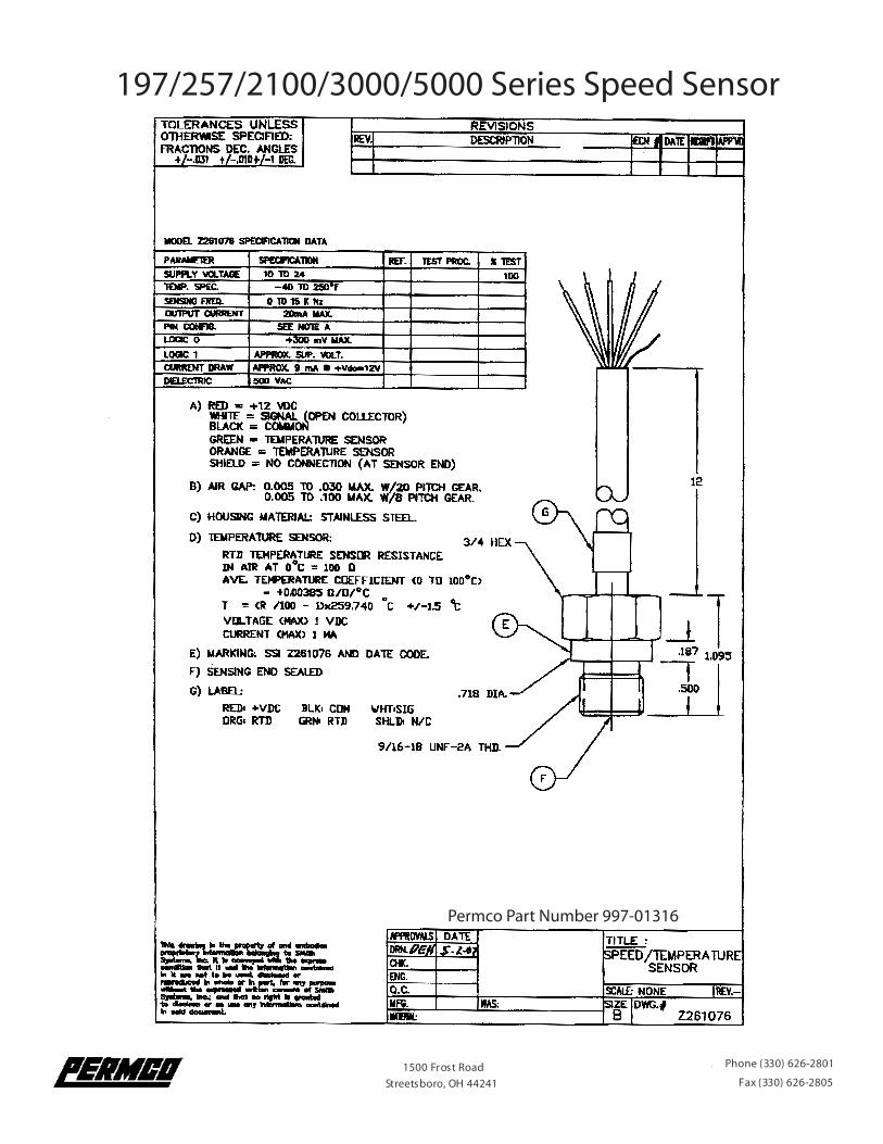
1500 Frost Road Streetsboro, OH 44241
Phone (330) 626-2801
Fax (330) 626-2805
197/257/2100/3000/5000 Series Speed Sensor
1500 Frost Road Streetsboro, OH 44241
Phone (330) 626-2801
Fax (330) 626-2805
Permco Part Number 997-01316

Below is a 7500/7600 housing pictured with a SPECIAL 3/8” JIC port on the top. While this port is a standard JIC port, IT REQUIRES EXACT PLACEMENT IN THE HOUSING and must be done according to the drawing. The port is designed to accommodate our new speed sensor part number 997-01237 which is used with our new speed control box part number 997-01238. You would also need a wiring harness part number 997-01238WH. For more information please refer to the Genesis brochure which is available as a PDF or in hard copy.The code for this new housing is “SS”. Example, P7600A467ZD(SS)NM17-00DVBP.
C opy r igh t © 2 0 0 6 P e r m c oB ulle t in # G S 0 6 - 1 0 0 A