polarizing microscope labophot -pol - mvi-inc.com · cautions o avoid sharp knocks l handle the...
TRANSCRIPT
Nikon
Polarizing Microscope
LABOPHOT -POL
INSTRUCTIONS
NIPPON KOGAKU K. K.

CAUTIONS
oAvoid sharp knocks lHandle the microscope gently, taking care
to avoid sharp knocks.
_When carrying the microscopeWhen carrying the microscope, hold its armwith one hand, supporting the bottom ofthe microscope base with the other. The
instrument weighs about 8 kg.
8Place for usingAvoid the use of the microscope in a dusty
place, where it is subject to vibrations orexposed to high temperatures, moisture ordirect sunlight.
oPower source voltage..,...ForEuropean districts only-Make sure of the power source voltage,220V or 240V, by means of the input
voltage change-over switch wh ich is on thebottom of the microscope base.
o Exchanging the lamp bulb and fuseBefore replacing the lamp bulb (6V-20W)
or fuse, turn OF F the power switch anddisconnect the plug of the power sourcecord.In such cases as of replacement, do not
touch the lamp bulb with bare hands, immediately after putting out the lamp.
(it Dirt on the lensDo not leave dust, dirt or finger marks onthe lens surfaces.
They will prevent you from clear observation of the specimen image.
2
~Strain-free glassesThe optical elements of this microscope
being constructed of strain-free glasses,ta ke particular caution in hand Iing theobjectives and condenser lenses not tocause strain to them.
8Focus knobsNever attempt to adjust the tightness ofthe right- and lefthand focus knobs byturning the one, while holding the other in
this model microscope, because of causingdisorder.
CARE AND MAINTENANCE
o Cleaning the lensesTo clean the lens surfaces, remove dust
using a soft hair brush or gauze. Only forremoving finger marks or grease, shouldsoft cotton cloth, lens tissue or gauze
lightly mo istened with absolute alcohol(methanol or ethanol) be used.
For cleaning the objectives and immersionoil use only xylene.Observe sufficient caution in handlingalcohol and xylene.
f) Cleaning the painted surfacesAvoid the use of any organic solvent (forexample, th inner, ether, alcohol, xyleneetc.) for cleaning the painted surfaces andplastic parts of the instrument.
8Never attempt to dismantle!Never attempt to dismantle the instrument
so as to avoid the possibility of impairingthe operational efficiency and accuracy.
OWhen not in useWhen not in use, cover the instrument with
the accessory vinyl cover, and store it in a
place free from moisture and fungus.It is especially recommended that the
objectives and eyepieces be kept in anairtight container containing desiccant.
oPeriodical checkingTo maintain the performance of the instrument, we recommend to check the instruments periodically. (For details of thischeck, contact our agency.)
3
CONTENTS
I. NOMENCLATURE 4
II. ASSEMBLy 6
III. PREPARATION 8
1. Interpupillary Distance Adjustment 82. Diopter Adjustment 83. Optical Path Change-over in the
Trinocular Eyepiece Tube "TP" 8
4. Centering the Objectives 85. Centering the Condenser Lens 96. Orientation of the Dia-polarizer 9
IV. MICROSCOPY 10
1. Operating Procedure 102. Manipulation of Each Element 11
1) Focusing 112) Condenser aperture diaphragm 113) Field diaphragm 11
4) Circular graduated stage 115) Objectives 116) Eyepieces 127) Achromat strain-free condenser 128) Bertrand lens 12
9) 1/4 A & tint plate 1310) Dia-polarizer and analyzer _ 1311) Filters 14
12) Illumination system 14
V. PHOTOMiCROGRAPHy 15
VI. ACCESSORIES 17
1. 5enarmont Compensator 17
2. Quartz Wedge 17
3. Monocular Eyepiece Tube "AP" 184. Epi-illuminator "M" 185. Attachable Mechanical Stage Type "E". 19
VII. TROUBLE SHOOTING TABLE 20
REFERENCE 23
ELECTRIC SPECIFICATIONS 23

I .NOMENCLATURE
Binocular eyepiece tube "BP"
Interpupillary distance scale
Diopter ring
CF eyepiece
Eyeguard
Bertrand lens flip-in/out ring
Centering nosepiece
CF Achromat P objective
(strain-tree)
Circular graduated stage
Circular graduated stageclamp screw
Vernier
Achromat strain-free condenser
Filters
(B& GIF)
Dust cap
4
Eyepiece tube clamp screw
Analyzer in/out knob
Intermediate tubeclamp screw
Coarse focus knob
Fine focus knob
Orientation plate
Filter receptacle
Fig. 1
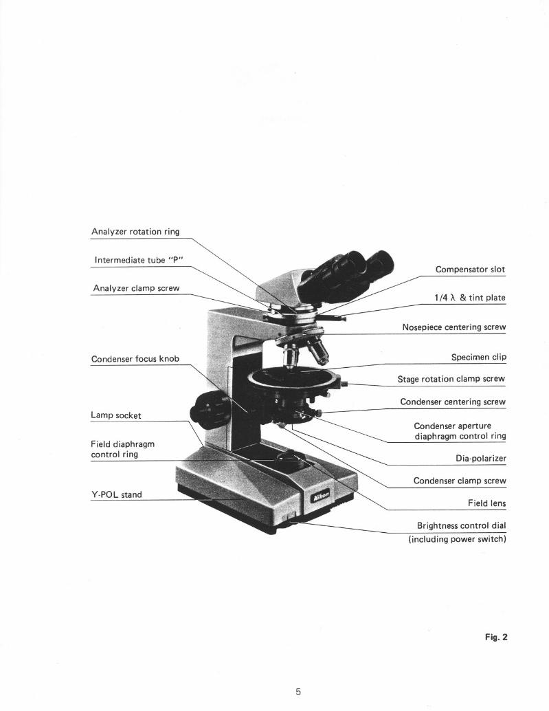
Analyzer rotation ring
Intermediate tube "P"
Analyzer clamp screw
Condenser focus knob
Lamp socket
Field diaphragmcontrol ring
V-POL stand
5
Compensator slot
1/4 A & tint plate
Nosepiece centering screw
Specimen clip
Stage rotation clamp screw
Condenser centering screw
Condenser aperturediaphragm control ring
Dia-polarizer
Condenser clamp screw
Field lens
Brightness control dial
(including power switch)
Fig.2
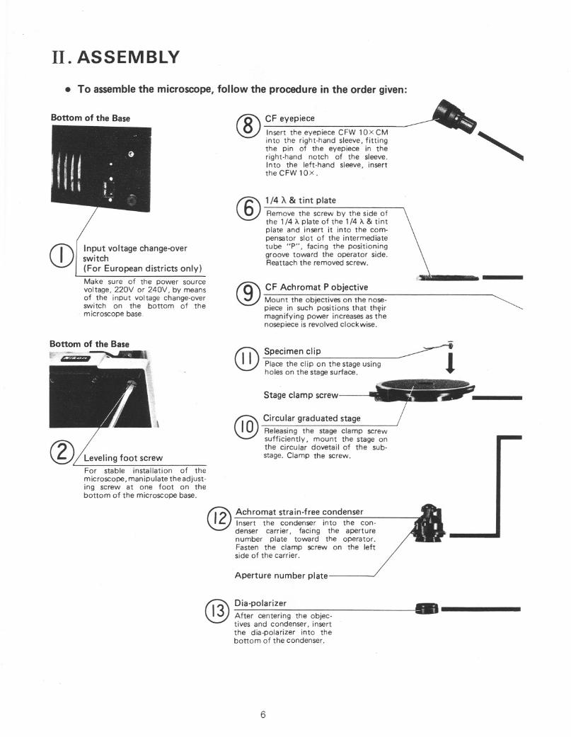
II. ASSEMBLY
1/4 A & tint plate
Remove the screw by the side ofthe 1/4 A plate of the 1/4 A & tintplate and insert it into the compensator slot of the intermediatetube "P", facing the positioninggroove toward the operator side.Reattach the removed screw.
®
® CF Achromat P objectiveMount the objectives on the nosepiece in such positions that thfilirmagnifying power increasesas thenosepiece is revolved clockwise.
Input voltage change-overswitch(For European districts only)
Make sure of the power sourcevoltage, 220V or 240V, by meansof the input voltage change-overswitch on the bottom of themicroscope base_
• To assemble the microscope, follow the procedure in the order given:--'CF eyepiece _
® Insert the eyepiece CFW 10XCM- '"
into the right-hand sleeve, fittingthe pin of the eyepiece in theright-hand notch of the sleeve.Into the left-hand sleeve, insertthe CFW lOx.
Bottom of the Base
CD
@2 Achromat strain-free condenserInsert the condenser into the condenser carrier, fad ng the aperturenumber plate toward the operator.Fasten the clamp screw on the leftside of the carrier.
Aperture number plate
•.----
Specimen clip
Place the clip on the stage usingholes on the stage surface.
Stage clamp screw
Circular graduated stage
Releasing the stage clamp screwsufficiently, mount the stage onthe circular dovetail of the substage. Clamp the screw.
Dia-polarizer
After centering the objectives and condenser, insertthe dia-polarizer into thebottom of the condenser.
@
@)
@
Leveling foot screwFor stable installation of themicroscope, manipulate the adjusting screw at one foot on thebottom of the microscope base.
6
•---------. ?:=:
Y·POL stand
@T:.er
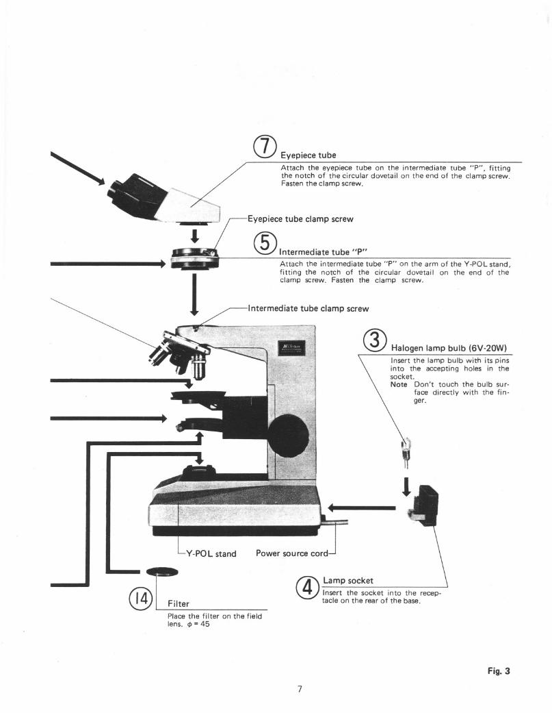
(]) Eyepiece tube
Attach the eyepiece tube on the intermediate tube "P", fittingthe notch of the circular dovetail on the end of the clamp screw.Fasten the clamp screw.
Eyepiece tube clamp screw
® Intermediate tube "P"
Attach the intermediate tube "P" on the arm of the V-POL stand,fitting the notch of the circular dovetai I on the end of theclamp screw. Fasten the clamp screw.
Intermediate tube clamp screw
Halogen lamp bulb (6V-20W)
Insert the lamp bulb with its pinsinto the accepting holes in thesocket.Note Don't touch the bulb sur
face directly with the finger.
Power source cord
t4' Lamp socket~ Insert the socket into the receptacle on the rear of the base.
Place the filter on the fieldlens. <p = 45
Fig. 3
7
III. PREPARATION
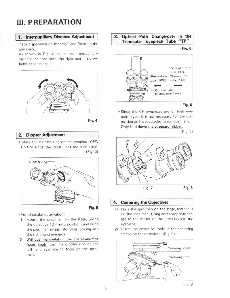
3.. Optical Path Change-over in the 1
Trinocular Eyepiece Tube "TP"(Fig. 6)
Fig. 8
Vertical phototube: 86%
Observat iontube: 14%
Optical pathchange-over knob
Fig. 7
Fig.6
'* Since the CF eyepieces are of high eye
point type, it is not necessary for the user
putting on his spectacles to remove them.Only fold down the eyeguard rubber.
(Fig.8)
I. 4. Centeringthe Objectives1) Place the specimen on the stage, and focus
on the specimen. Bring an appropriate target to the center of the cross lines in theeyepiece.
2) Insert the centering tools in the centering
screws on the nosepiece. (Fig. 9)
(For binocular observation)
1) Mount the specimen on the stage. Swingthe objective 10 x into position, and bringthe specimen image into focus looking into
the right-hand eyepiece.2) Without manipulating the coarse-and-fine
focus knob, turn the diopter ring on theleft-hand eyepiece to focus on the specimen.
Fig. 5
____ JFig. 4
2. Diopter Adjustment
Rotate the diopter ring on the eyepiece CFW10X CM until the cross lines are seen clear.
(Fig.5)
1. ·Interpupiflary DistanceAdjustment I
Place a specimen on the stage, and focus on thespecimen.As shown in Fig. 4, adjust the interpupillarydistance, so that both the right and left viewfields become one.
Fig.98
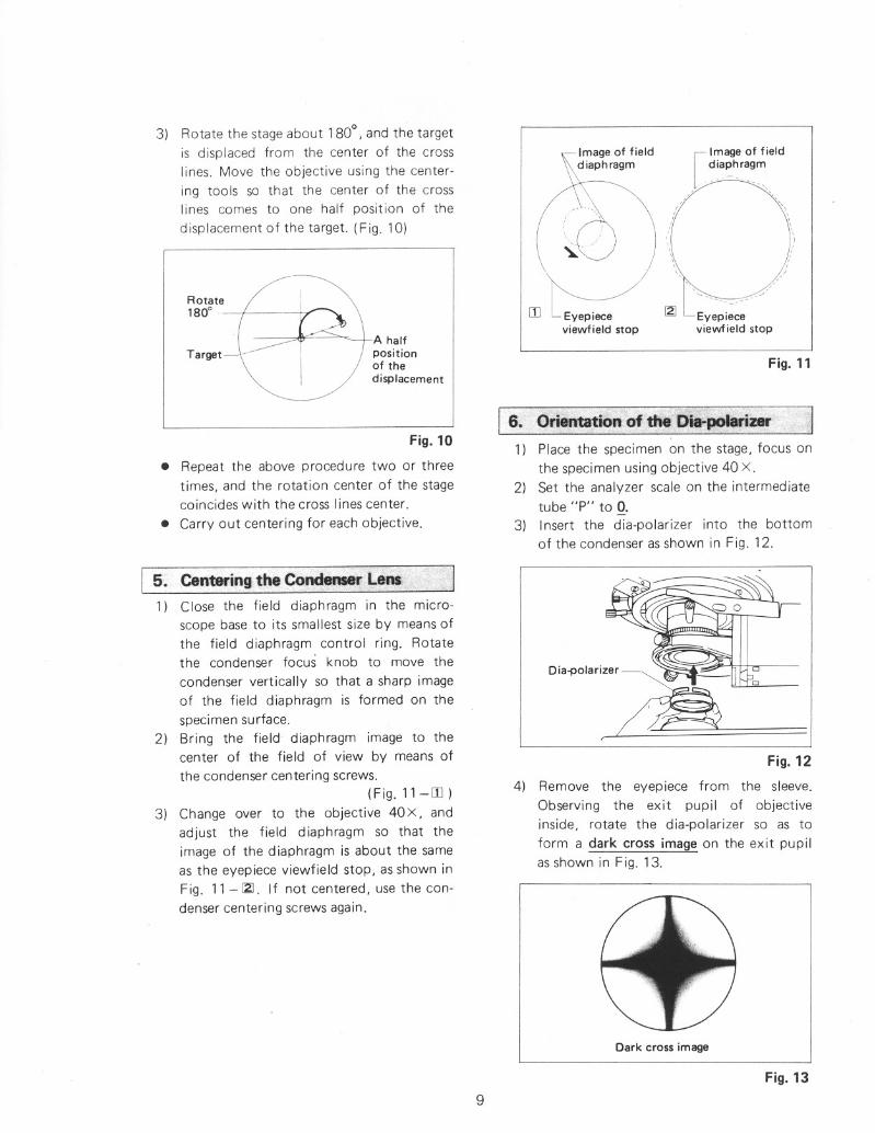
Fig. 10
• Repeat the above procedure two or threetimes, and the rotation center of the stagecoincides with the cross lines center.
• Carry out centering for each objective.
Fig. 11
Eyepieceviewfield stop
[.Im ..ageof field
diaphragm
iT \,,/,\\
\ ....(')\.i \\~~) )
rn~-/Eyepieceviewfield stop
6. Orientationof the Dii-pmarizer ·1
1) Place the specimen on the stage, focus on
the specimen using objective 40 X.
2) Set the analyzer scale on the intermediatetube "P" to O.
3) Insert the dia-polarizer into the bottomof the condenser as shown in Fig. 12.
A halfpositionof thedisplacement
Rotate1800 .
Target
3) Rotate the stage about 1800, and the targetis displaced from the center of the crossIines. Move the objective using the center
ing tools so that the center of the crossIines comes to one half position of the
displacement of the target. (Fig. 10)
Di'''OI''i''~~~
Fig. 12
4) Remove the eyepiece from the sleeve.
Observing the exit pupil of objective
inside, rotate the dia-polarizer so as to
form a dark cross image on the exit pupilas shown in Fig. 13.
5. Centeringtbe Condenser Le~' ~I
1) Close the field diaphragm in the micro
scope base to its smallest size by means ofthe field diaphragm control ring. Rotatethe condenser focus knob to move the
condenser vertically so that a sharp imageof the field diaphragm is formed on thespecimen surface.
2) Bring the field diaphragm image to thecenter of the field of view by means ofthe condenser centering screws.
(Fig. 11-[I])3) Change over to the objective 40 x, and
adjust the field diaphragm so that theimage of the diaphragm is about the sameas the eyepiece viewfield stop, as shown in
Fig. 11 - ~. If not centered, use the condenser centering screws again.
Dark cross image
Fig. 139

IV. MICROSCOPY
A~> .... v: " >,,' ,<' ,:¥f:~i-0":'.?~~G+:t
..O~~atingProeed~ri'f/Ji ~,:,fr%: ~
1) Turn the brightness control dial (includingpower switch) to light the lamp.
2) Bring the analyzer and the Bertrand lens out ofthe optical path. (Refer to P. 12 & 13)
3) Place the specimen on the stage and swing the10X objective into position. Focus on specimen.
4) Adjust the interpupillary distance and diopter.(Refer to P. 8)
5) Placethe filter on the field lens.
6) Carry out the centering procedure for theobjective. (Refer to P. 8)
7) Carry out the centering procedure for the condenser. (Refer to P. 9)
8) Bring the analyzer into the optical path.
9) Swing in the objective to be used and refocus onspecimen.
10) Brightness is adjusted by changing the lampvoltage.
Table 1
OrthoscopicConoscopicmicroscopy
microscopy
lOX orIN
Top lens ofhigher
INcondenser 4X orOUTlowerBertrand lens
OUTIN
CircumscribedlOX or
70% ~ 80% of thethe circumfer-
numerical apertureence of theAperture
higherof the objectiveconoscoplCdiaphragm 4X or
field of viewFully opened
(or fullylower opened)Circumscribed the
CircumscribedlOx or
circumference ofthe circumfer-Field
higherthe eyepiece fieldence of thediaphragm
of vieworthoscopic
4x orFully opened
field of view
lower
10
i·~-I
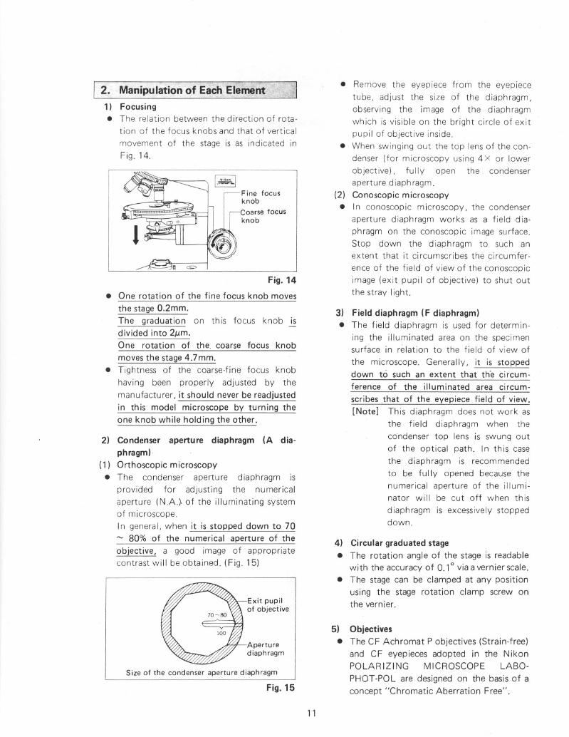
Size of the condenser aperture diaphragm
Fig. 14
3) Field diaphragm (F diaphragm)
• The field diaphragm is used for determin
ing the illuminated area on the specimensurface in relation to the field of view of
the microscope. Generally, it is stopped
down to such an extent that th'e circum
ference of the illuminated area circum
scribes that of the eyepiece field of view.
[Note] This diaphragm does not work as
the field diaphragm when the
condenser top lens is swung out
of the optical path. In th is case
the diaphragm is recommended
to be fully opened because the
numerical aperture of the illuminator will be cut off when this
diaphragm is excessively stoppeddown.
4) Circular graduated stage
• The rotation angle of the stage is readable
with the accuracy of 0.10 via a vernier scale.
• The stage can be clamped at any position
using the stage rotation clamp screw onthe vernier.
• Remove the eyepiece from the eyepiece
tube, adjust the size of the diaphragm,
observing the image of the diaphragm
which is visible on the bright circle of exit
pupil of objective inside.
• When swinging out the top lens of the con
denser (for microscopy using 4x or lower
objective), fully open the condenser
apertu re d iaph ragm.
(2) Conoscopic microscopy
• In conoscopic microscopy, the condenser
aperture diaphragm works as a field dia
phragm on the conoscopic image surface.
Stop down the diaphragm to such anextent that it circumscribes the circumfer
ence of the field of view of the conoscopic
image (exit pupil of objective) to shut out
the stray light.
5) Objectives
• The CF Achromat P objectives (Strain-free)
and CF eyepieces adopted in the NikonPOLARIZING MICROSCOPE LABO
PHOT-POL are designed on the basis of a
concept "Chromatic Aberration Free".
Exit pupilof objective
Aperturediaphragm
Fine focusknob
,-Coarse focusknob
Fig.15
2. Manipulation of EachEleme~t } _;11) Focusing• The relation between the direction of rota
tion of the focus knobs and that of vertical
movement of the stage is as indicated in
Fig. 14.
• One rotation of the fine focus knob moves
the stage 0.2mm.
The graduation on this focus knob ~divided into 211m.
One rotation of the. coarse focus knob
moves the stage 4.7mm.
• Tightness of the coarse-fine focus knob
having been properly adjusted by the
manufactu rer, it should never be readjusted
in this model microscope by turning the
one knob while holding the other.
2) Condenser aperture diaphragm (A dia
phragm)-(1) Orthoscopic microscopy
• The condenser aperture diaphragm is
provided for adjusting the numerical
aperture (N.A) of the illuminating system
of microscope.
In general, when it is stopped down to 70
~ 80% of the numerical aperture of the
objective, a good image of appropriate
contrast will be obtained. (Fig. 15)
11

In every case use the CF objectives in combination with the CF eyepieces.
(1) Oil immersion objectives (Oil)• Objective CF Achromat P 100x (Oil), an
oil-immersion type, is to be immersed in oilbetween the specimen and front of the
objective.To see if air bubbles are present in the immersion oil, which deteriorate the image
quality, pull out the eyepiece from theeyepiece tube to examine the objective exitpupil inside the tube. To remove air bubbles, revolve the nosepiece slightly to andfro several times, apply additional oil, orreplace the oil. Be careful not to rotate thenosepiece too far as to soil the ends of the
other objectives with oil.• To clean off the oil, pass lens tissue or soft
cloth moistened with xylene lightly two orthree times over the lens. It is essential at
this time to avoid touching the lens withthe part of tissue or cloth once used.
(2) Coverglass• With the objectives engraved "160/0.17",
use a coverglass of O.17mm in thickness.• The indication "160/-" on the objective
means that no matter whether a coverglass
is used or not, no decrease of image definition or of contrast will result.
6) Eyepieces
• To take full advantage of the CF eyepieces,use them in combination with the CF
objectives.• By inserting the eyepiece with cross lines
and graduation (CFW 1OXCM) into the
eyepiece sleeve fitting the protractor pininto the right-hand side groove of thesleeve, the a-direction of the analyzer anddia-polarizer are al igned with the cross linesdirection.
If the protractor pin is fitted to the upperright side groove of the sleeve, the crosslines will be aligned with the diagonal posi
tion of the polarizaiton.
• CF PL Projection lenses are exclusivelydesigned for photom icrography. Do notuse them for observation.
• For focusing with the observation tube of
the trinocular eyepiece tube for photo-
12
micrography, use the eyepiece incorporat
ing the photo mask.
7) Achromat strain-free condenser
• The top lens of the condenser is to be
placed in the optical path for the ortho
scopic and conoscopic microscopy provid
ed that it is to be swung out when anobjective of 4X or lower magnification isin use.
[Note] For the orthoscopic microscopy,a lower numerical aperture illumination with the top lens swung incondenser was used to be recom
mended, however, th is method isnot effective especially for highmagnification observation because
of the lowered resolution. Hence,for the latter case, use of the top
lens may rather be recommendable except the retardation measurement or the interference colorobservation for wh ich it is neces
sary to make the illumination
light flux as parallel as possible to
the optical axis by swinging outthe top lens or stopping down theaperture diaphragm.
• Thickness of the glassslide must be 1.7mmor less, otherwise, the field diaphragm
might fail to focus its image on the specimen.
8) Bertrand lens
(with the trinocular eyepiece tube "TP" orthe binocular eyepiece tube "BP" in use)
• Bring the Bertrand lens into the opticalpath by turning the Bertrand lens ringleftward to observe the conoscopic image.
(Fig. 16)
Bertrand lensflip-in/out ring
Fig. 16
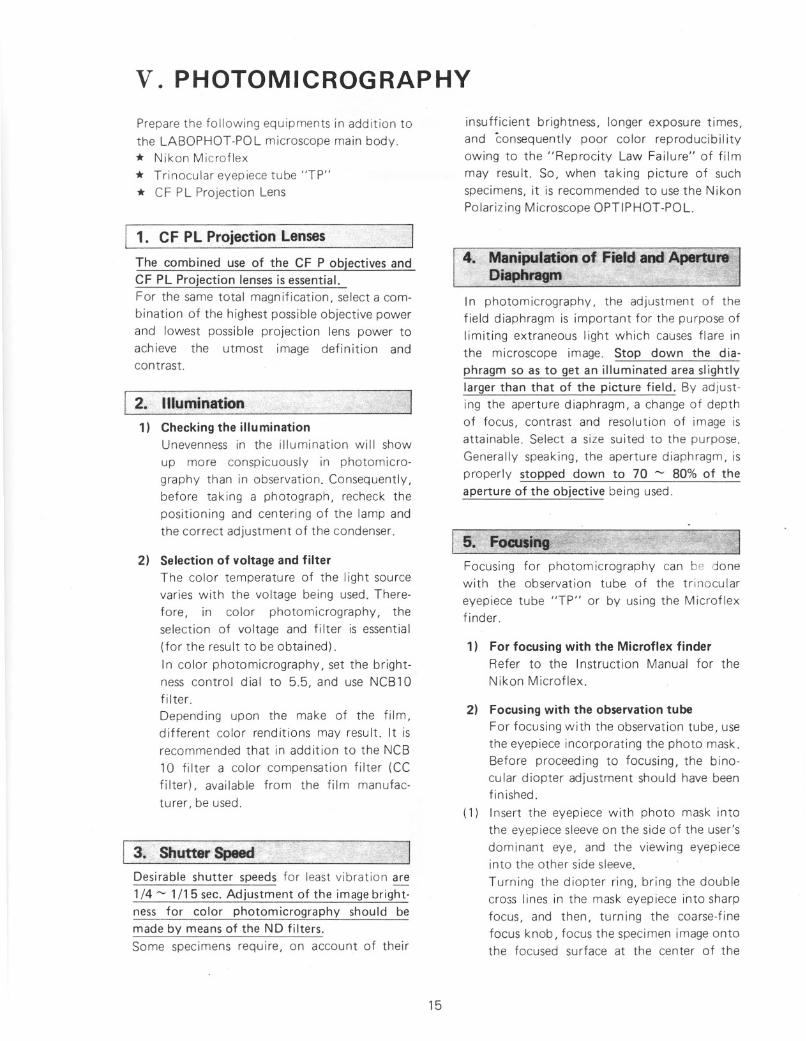
Orientationplate .
1/4A plate
Empty holeSensitive tint plate
Fig. 20
• As the orientation of the d ia-polarizer
slightly changes when centering the condenser, check the orientation after centering the condenser.
• The analyzer rotates 1800 via the rotation
ring the left-hand side clamp being released. The rotation angle is readable withaccuracy of 0.10 via the vernier.
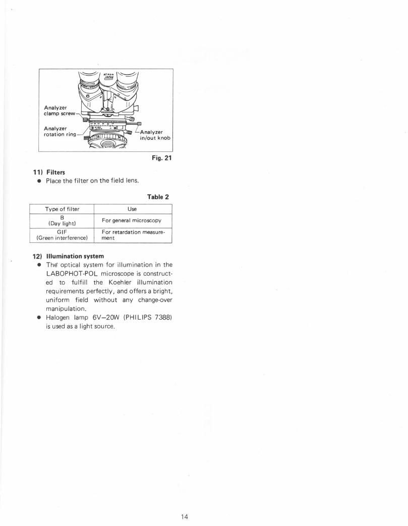
Fig. 19
• The test plate has an empty hole at the
center. By pushing it through the slot, thesensitive tint plate (530nm) is broughtinto the optical path and by pulling it out
the 1/4 A plate is brought into the opticalpath.
10) Dia-polarizer and analyzer
• When the both are set at Q reading on theprotractor scale, position of the polarization plane coincides with the orientation
plate (X-direction for polarizer, Y -directionfor analyzer) on the microscope base.
-(Fig. 20)[Note] Some of the reference books or
special works about polarizingmicroscope available in themarket explain that X-direction is
for analyzer and V-direction forpolarizer.
Conoscopic imageof this area can beobserved
Orthoscopic viewfield
~Pin hole eyepiece
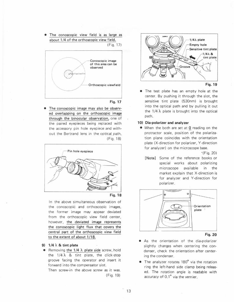
In the above simultaneous observation of
the conoscopiC and orthoscopic images,
the former image may appear deviatedfrom the orthoscopic view field center,
however, the deviated image representsthe conoscopic Iight flux that covers thecentral part of the orthoscopic view fieldto the extent of about 1/18 .
Fig. 18
• The conoscopic view field is as large asabout 1/4 of the orthoscopic view field.
(Fig. 17)
Fig. 17
• The conoscopic image may also be observ
ed overlapping on the orthoscopic imagethrough the binocular observation, one ofthe paired eyepieces being replaced with
the accessory pin hole eyepiece and without the Bertrand lens in the opti"cal path.
(Fig. 18)
9) 1/4 A & tint plate• Removing the 1/4 A plate side screw, hold
the 1/4 A & tint plate, the click-stopgroove facing the operator and insert itforward into the compensator slot.Then screw-i n the above screw as it was.
(Fig. 19)
13
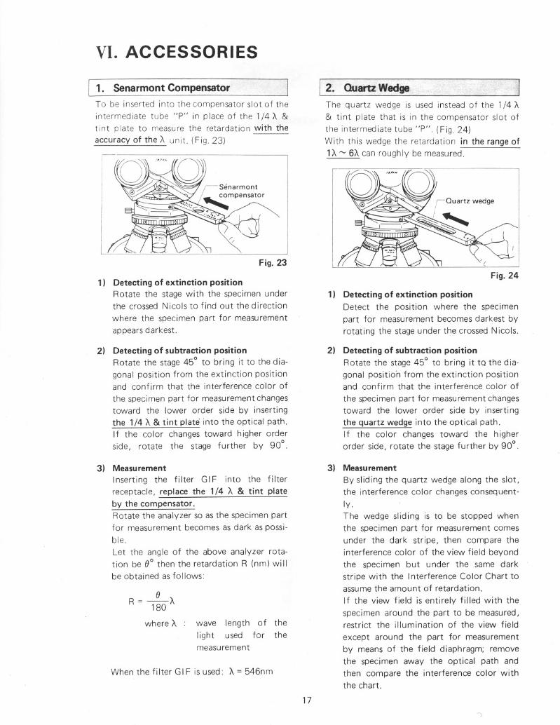
Analyzerclamp screw
Analyzerrotation ring Analyzer
in/out knob
Fig. 21
11) Filters• Place the filter on the field lens.
Table 2
Type of filter Use
BFor general microscopy(Day light)
GIF
For retardation measure-(Green interference)
ment
12) Illumination system• The optical system for illumination in the
LABOPHOT-POL microscope is constructed to fulfill the Koehler illumination
requ irements perfectly, and offers a bright,un iform field without any change-over
manipulation.
• Halogen lamp 6V-20W (PHI LIPS 7388)is used as a light source.
14
V.PHOTOMICROGRAPHY
Prepare the following equipments in addition to
the LABOPHOT-POL microscope main body.* Nikon Microflex
* Trinocular eyepiece tube "TP"
* CF PL Projection Lens
1. CF Pl Projection lenses
The combined use of the CF P objectives andCF PL Projection lenses is essential.For the same total magnification, select a com
bination of the highest possible objective powerand lowest possible projection lens power toachieve the utmost image definition andcontrast.
2. Illumination
1) Checkingthe illuminationUnevenness in the illumination will show
up more conspicuously in photomicrography than in observation. Consequently,before taking a photograph, recheck the
positioning and centering of the lamp andthe correct adjustment of the condenser.
2) Selection of voltageand filterThe color temperatu re of the Iight sourcevaries with the voltage being used. There
fore, in color photomicrography, theselection of voltage and filter is essential(for the result to be obtained).
In color photomicrography, set the brightness control dial to 5.5, and use NCB10filter.
Depending upon the make of the film,different color renditions may result. It isrecommended that in addition to the NCB
10 filter a color compensation filter (CCfilter), available from the film manufac
turer, be used.
3. Shutter Speed
Desirable shutter speeds for least vibration are1/4 ~ 1/15 sec. Adjustment of the image bright
ness for color photomicrography should bemade by means of the NO filters.
Some specimens require, on account of their
15
insufficient brightness, longer exposure times,and consequently poor color reproducibilityowing to the "Reprocity Law Failure" of filmmay result. So, when taking picture of suchspecimens, it is recommended to use the N ikon
Polarizing Microscope OPTIPHOT-POL.
4. Manipulation of Field and ApertureDiaphragm
In photomicrography, the adjustment of thefield diaphragm is important for the purpose oflimiting extraneous light which causes flare in
the microscope image. Stop down the diaphragm so as to get an illuminated area slightlylarger than that of the picture field. By adjusting the apertu re diaphragm, a change of depthof focus, contrast and resolution of image isattainable. Select a size suited to the purpose.
Generally speaking, the aperture diaphragm, isproperly stopped down to 70 ~ 80% of theaperture of the objective being used.
5. FOC;USingFocusing for photomicrography can be donewith the observation tube of the trinocular
eyepiece tube "TP" or by using the Microflexfinder.
1) For focusing with the Microflex finderRefer to the Instruction Manual for theNikon Microflex.
2) Focusingwith the observationtubeFor focusing with the observation tube, use
the eyepiece incorporating the photo mask.Before proceeding to focusing, the binocular diopter adjustment should have beenfinished.
(1) Insert the eyepiece with photo mask intothe eyepiece sleeve on the side of the user'sdominant eye, and the viewing eyepieceinto the other side sleeve.
Turning the diopter ring, bring the doublecross lines in the mask eyepiece into sharpfocus, and then, turning the coarse-finefocus knob, focus the specimen image ontothe focused surface at the center of the

mask. For diopter adjustment in the othereyepiece, do not manipulate the focusknob, but the diopter ring to bring theimage into focus, with the objective 4 x orlOx.
(2) Turning the eyepiece as a whole, set it insuch a position that the photo mask ap
pears as shown in Fig. 22 .
Inner frame
~ Intermediateframe
Outer frame
Mask eyepiece viewfield
Fig. 22
(3) Furthermore, when using a low power
objective, place the focusing telescope overthe mask eyepiece, thus constructing aneyepiece of higher magnification, to perform precise focusing.
3) Magnifications of CFPL Projection lensessuitable for each frame size of photo maskRefer to Table 3.
Table 3. Magnifications of CF PL Projectionlenses Suitable for Frame Size ofPhoto Mask
CFPLPro-Large form at
Type of film
adapterjection lens magnification
~ <ll
35 mm 2.5x-------------~ E
::> roO~4" x 5" 2.5x4x
~
35mm 4x~ro
'6<ll
4" x 5" 4x4x<ll E E ro
I~ ~ 3%" x 4%" 2.5X4x~-.- c 6x9 2.5x4x
35mm
5x~~ <ll
~ E 4" x 5"5x4xc ~ --.- 3%" x 4%"
4x4x
For photomicrography, when focusingwith the binocular observation tube, use
the CF eyepiece, CF PL Projection lens and
16
CF Photo Mask eyepiece, with the magnification and other indications engraved in
yellow, or in white with a white dot inaddition.
6. Others• As the intermediate tube "P" of LABO
PHOT-POL microscope builts in thedepolarizer, it's not necessary to give careto the relation between the orientation of
the polarizer, analyzer and the position ofthe Microflex .
• For the use of other photom icrograph icattachments refer to the pertinent instruction manuals.
VI. ACCESSORIES
1. Senarmont Compensator
To be inserted into the compensator slot of theintermediate tube "P" in place of the 1/4 \ &
tint plate to measure the retardation with the
accuracy of the \ unit. (F ig 23)
Fig. 23
1) Detecting of extinction positionRotate the stage with the specimen underthe crossed Nicols to find out the direction
where the specimen part for measurementappears darkest.
2) Detecting of subtraction positionRotate the stage 45° to bring it to the dia
gonal position from the extinction positionand confirm that the interference color of
the specimen part for measurement changestoward the lower order side by insertingthe 1/4 \ & tint plate into the optical path.If the color changes toward higher orderside, rotate the stage further by 90°.
2. Quartz Wedge
The quartz wedge is used instead of the 1/4 \& tint plate that is in the compensator slot of
the intermediate tube "P" (Fig 24)With this wedge the retardation in the range of1\ ~ 6\ can roughly be measured.
Fig. 24
1) Detecting of extinction positionDetect the position where the specimen
part for measurement becomes darkest byrotating the stage under the crossed Nicols.
2) Detecting of subtraction positionRotate the stage 45° to bring it tQ the diagonal positio·n from the extinction positionand confirm that the interference color of
the specimen part for measurement changestoward the lower order side by insertingthe quartz wedge into the optical path.If the color changes toward the higherorder side, rotate the stage fu rther by 90°.
When the fi Iter GI F is used: \ = 546nm
3) MeasurementInserting the filter GIF into the filterreceptacle, replace the 1/4 \ & tint plate
by the compensator.Rotate the analyzer so as the specimen partfor measurement becomes as dark as possible.
Let the angle of the above analyzer rotation be 8° then the retardation R (nm) willbe obtained as follows:
_8\R = 180
where \ wave length of the
light used for themeasurement
17
3) Measurement
By sliding the quartz wedge along the slot,the interference color changes consequently.The wedge sliding is to be stopped whenthe specimen part for measurement comesunder the dark stripe, then compare theinterference color of the view field beyondthe specimen but under the same dark
stripe with the Interference Color Chart toassume the amount of retardation.
If the view field is entirely filled with the
specimen around the part to be measured,restrict the illumination of the view field
except around the part for measurementby means of the field diaphragm; remove
the specimen away the optical path andthen compare the interference color withthe chart.

1;3. 'Monocular£yepiece Tube 66Ap6I
\Pin hole swing-in/out knob\ ~Monocular eyepiece
'--" tube "AP"
Bertrand lens I~in/out turret
Bertrand lens ~focus turret I
Fig. 25
1) Bertrand lens
The Bertrand lens is brought in and out ofthe optical path by turning the Bertrandlens tu rret.
The lens is in the optical path when theindication on the turret is B.
The Bertrand lens can be focused by turning the focus turret located under theBertrand lens turret.
2) Pin-hole knob
The pin hole can be put in or out of the
optical path by operating the pin holeknob located right-hand side of the eyepiece sleeve.By means of the pin hole, the conoscopicimage covering the area of 10J.1m¢ on thespecimen surface (when a 100 x objectiveis used) can be observed.
4. Epi-iliuminator 81M"
Used for episcopic polarizing microscopy,mounted between the Y-PO L stand and theintermed iate tube "P".
1) Nomenclature and assembly
• Referring to Fig, 26, assemble in the order
given.CD Remove the eyepiece tube and the inter
mediate tube "P" from the Y -POL stand.
@ Mount the epi-illuminator "M" on themicroscope arm, positioning the illumina
tor nearly parallel to the arm. Clamp thescrew.
® After releasing sufficiently the clampscrew on the lamp housing, to which thelamp bulb (6V-20W Halogen lamp) andsocket is attached, insert the lamp housinginto the epi-illuminator "M" and clamp thescrew.
@) Connect the lamp cord to the transformer.
® Place the epi-polarizer into the slot, facingthe white index dot toward the mirror.[Note] Insertion arid removal of the epi
polarizer should be made with a
half-reflecting mirror brought outof the optical path.
® Place the filters.(j) Mount the intermediate tube "P" on the
illuminator "M", positioning the tube withits "Nikon" plate faced to the operator,regardless of the groove of the intermediatetube "P" mount. Fasten the tube tentative-
Transformer'4'=- •
~- Lamp verticalcentering ring
Lamp housing clamp screw,-Socket sleeve clamp screw
--Lamp lateral centering screw
~l'-----Lamp housing
"---Epi-illuminator "M"
'-Half-reflecting mirrorswing-in/out knob
"--"
~Slot for epi-polarizer
"'-",-
L filter--
Intermediate tube Il~clamp screw - I ~
-, l(V
White index dot --
Epi-polarizer ------
NeB 10 filter
Intermed iatetube "P"
Microscope arm
ND16 or GIF filter--
Fig. 26
18
Iy using the clamp screw on the illuminator"M".Secure clamping of the tube is to be doneafter completing the orientation of analyzer 2)-(2).
]:: Referring to P. 7, mount the eyepiece tubeon the intermediate tube "P".
2) Preparation
(1) Centering the lamp
CD Turn the half-reflecting mirror swing-outknob counterclockwise to set the mirror
in the optical path.
@ Remove the L filter.® Place the ND filter on the stage and focus
on it using objective 1Ox.
@) Remove the eyepiece from the sleeve,
looking into the exit pupil of objective,move the lamp housing back and forth toform a sharp image of the lamp filamenton the diffuser of exit pupil.
® Manipulate the lamp centering screws tocenter the filament image on the exit pupil.
® Place the L filter.If the image is found too dark with an
objective of 40X or higher, remove the Lfilter.
(2) Orientation of analyzer (intermediate tubeliP")
CD Nearly focus on the ND filter on the stageusing objective 40x.
@ Set the analyzer graduation to "0".® Slightly release the intermediate tube
clamp screw on the epi-illuminator "M",detect the orientation of the intermediatetube "P" to form the dark cross image on
the exit pupil of objective (Refer to Fig.13), and in th is position clamp the intermediate tube "P".
3) ObjectivesUse the objectives CF M Plan Achromat Pseries (Strain-free, 210/45).
4) For manipulation and microscopy, refer todiascopic polarizing microscopy.
19
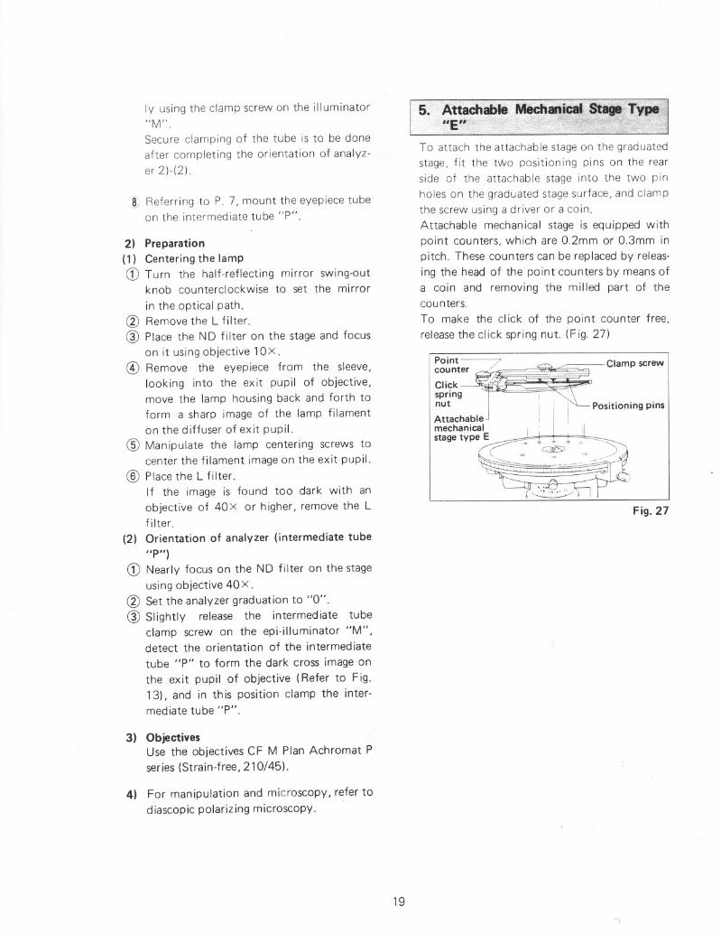
5. Attachable Mechanical, Stage: Type"'.IE" is "
To attach the attachable stage on the graduated
stage, fit the tWo positioning pins on the rearside of the attachable stage into the two pin
holes on the graduated stage surface, and clampthe screw using a driver or a coin.
Attachable mechanical stage is equipped withpoint counters, which are 0.2mm or 0.3mm inpitch. These counters can be replaced by releas
ing the head of the point counters by means ofa coin and removing the milled part of thecounters.
To make the click of the point counter free,
release the click spring nut. (Fig. 27)
~~~~\~r 7 !~.ff~~'-Clampscrew
spring - I I ' .
nut I i 1"-'---- Positioning pmsAttachable I I
meChanica~1 .11 .•• II
stage type E~-="":~="'=~~.~1":==J,r=~"'~=~,~---- - '---~ -}
~
Fig. 27

vu. TROUBLE SHOOTING TABLE
Although nowhere the user can find any disorder or derangement in the instrument, if heencounters some difficulty or dissatisfaction, recheck the use, referring to the table below:
1. Optical
Failures Causes)Actions
Darkness at the
• Optical path in trinocular tubel Changing-over to the limit
periphery or
not fully changed-over (Refer to P. 8)
uneven bright-
• Centering nosepiece not in click-l Revolve it to click-stop positionnessof view-
stop position (Objective notfield
centered in optical path)
(No appearance
• Condenser not centered ) Centering by using field
of viewfield)
diaphragm (Refer to P. 9)
• Field diaphragm too much closed
l Open it properly• Dirt or dust on the lens
) Cleaning
(Condenser, objective, eyepiece, slide) • Improper use of condenser
) Correct use (Refer to P. 10)
• Bertrand lens in the optical path
) Flip out (Refer to P. 12 & 18)
• Pin hole in the optical path
l Swing out (Refer to P. 18)
(in monocular eyepiece tube "AP") • Top lens of condenser incorrectly
l Swing in to the limit
positioned • 1/4 A. & tint plate, compensatorl Correct setting
or quartz wedge incorrectly positionedDirt or dust in
• Dirt or dust on the lens l Cleaningthe viewfield
(Condenser, objective, eyepiece,field lens)• Dirt or dust on the slide
l Cleaning
• Too low position of condenser
Correct positioning(Refer to P. 9)
No good image
• No coverglass attached to slidel Correct use (Refer to P. 12)
obtained (lowor NCG objective used with coverglass
resolution or• Too thick or thin coverglass) Use specified thickness (0.17mm)
contrast)
coverglass (Refer to P. 12)• Immersion oil soils the top of dry
) Cleaning
system objective (especially 40X) • Dirt or dust on the lens (condenser,l Cleaning
objective, eyepiece, slide) • No immersion oil used on immersion------- Use immersion oilsystem objective
(Refer to P. 12)
• Air bubbles in immersion oil
l Remove bubbles
• Not specified immersion oil used
l Use Nikon immersion oil
• Condenser aperture or field
l Open properly (Refer to P. 11)
diaphragm too much opened • Dirt or dust on the entrance lensl Cleaning
20
Failures Causes)Actions
Image quality
• Condenser aperture too much closed -----+ Open properly (Refer to P. 11)deteriorated
• Too low position of condenser) Bring it up to coincidence with
field diaphragm image(Refer to P. 9)Oneside dim-
• Centering nosepiece not in click-stop~ Revolve it to click-stop position
nessof image
position
Image moves
• Specimen rises from stage surfaceI Place it stable
while being• Centering nosepiece not in click-stop~ Revolve it to click-stop position
focusedposition
• Condenser not correctly centered' Correct centering (Refer to P. 9)
• Optical path in trinocular' Changing-over to the limit
I
tube not fully changed-over (Refer to P. 8)
Image tinged
• B filter not used ' Use B fi Iter
yellow
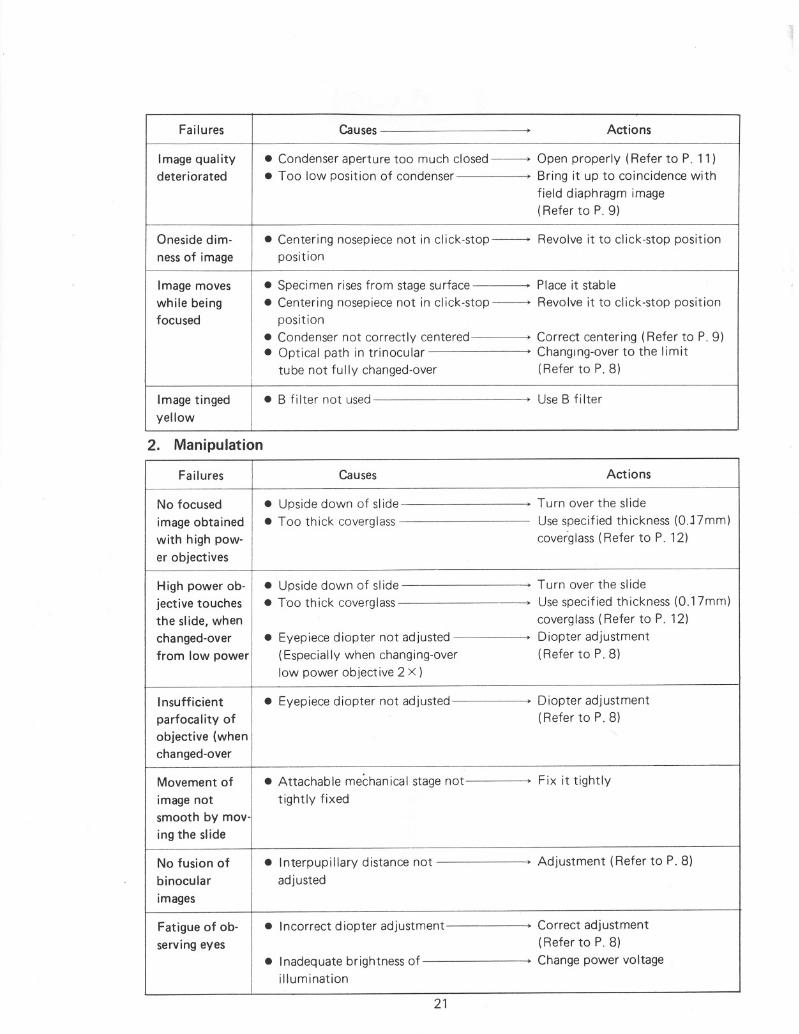
2. Manipulation
Failures Causes Actions
No focused
• Upside down of slide , Turn over the slide
image obtained
• Too thick coverglass Use specified thickness (O.J7mm)
with high pow-
coverglass (Refer to P. 12)
er objectivesHigh power ob-
• Upside down of slide ) Turn over the slide
jective touches
• Too thick coverglass-- Use specified thickness (O.17mm)
the slide, when
coverglass (Refer to P. 12)
changed-over
• Eyepiece diopter not adjusted' Diopter adjustment
from low power
(Especially when changing-over(Refer to P. 8)
low power objective 2 X)Insufficient
• Eyepiece diopter not adjusted) Diopter adjustment
parfocality of
(Refer to P. 8)
objective (when
"
changed-overMovement of
• Attachable mechanical stage not) Fix it tightly
image not
tightly fixed
smooth by mov- ing the slideNo fusion of
• Interpupillary distance not) Adjustment (Refer to P. 8)
binocular
adjusted
imagesFatigue of ob-
• Incorrect diopter adjustment) Correct adjustment
serving eyes
(Refer to P. 8)
• Inadequate brightness of
' Change power voltage
illumination
21

3. Electrical
Failures Causes)Actions
Lamp does not
• No electricity obtained I Connect the cord to socket
light even
• No lamp bulb attached I Attachingthough switch-
• Lamp bulb blown • Replacemented ON
• Fuse blown • Replacement
Unstable
• House current voltage fluctuates• Use transformer or the like (for
brightness of
too much adequate voltage)illumination
Lamp bulb
• Not specified lamp bulb used• Use 6V-20W specified lamppromptly
bulb: (Halogen bulb: PHI LIPSblown
7388)
• Too high voltage of house current
• Use transformer for adjustment
Insufficient
• Condenser not centered I Centering (Refer to P. 9)
brightness of
• Condenser aperture too much closed -------> Open it properly (Refer to P. 11)illumination
• Too low position of condenserI Correct positioning(Refer to P. 9)• Not specified lamp bulb used
• Use 6V-20W specified Halogenbulb (pHILIPS 7388)• Dirt on lens (condenser, objective,
l Cleaningeyepiece, field lens, filter) • Too low voltage
• Raise the voltage
Fuse blown
• Not specified fuse used • Use 1A/250V or O.5A/250V
Flickering or
• Lamp bulb going to be blown• Replacementunstable
• Lamp socket not inserted• Secure connection
brightness ofsufficiently
lamp bulb• Fuse holder not firmly fastened• Firm fastening
• Irregular change of house current
• Use stabilizer
voltage • Lamp bulb insufficiently inserted
• Positive connectioninto the socket
22

REFERENCE
This manual instructs only how to manipulate the LABOPHOTPOL microscope.
For the practical explanation on polarizing microscopy, refer
to the following special works:
• "AN INTRODUCTION TO THE METHODS OF OPTICALCRYST ALLOG RAPHY"
- F. Donald Bloss
Holt, Rinehart and Winston
• "ORE MICROSCOPY"
- Eugene N. CameronJohn Wiley & Sons. Inc.
• "THE POLARIZING MICROSCOPE"
- A. F. Hallimond
Vickers Instruments
ELECTRIC SPECIFICATIONS
100V
Power source
120V50/60Hz
220/240V
Halogen lamp
6V-20W
PH III PS 7388
100V}
1A/250VFuse120V
220/240V
O.5A/250V
We reserve the right to make such alterations in designas we may consider necessary in the light of experience.For this reason, particulars and illustrations in thishandbook may not conform in every detail to models incurrent production.
23

(Nikon)NIPPON KOGAKU K.K.Fuji Bldg., 2-3, 3 chome, Marunouchi,Chiyoda-ku, Tokyo 100, Japanft03-214-5311Telex: J22601 (NIKON)
Printed in Japan(81.12. e) H·E-3