plumbing, gas supply
TRANSCRIPT

Plumbing, Gas supply
Szikra Csaba
Department of Building Energetics and
Building Services

(1) Water Supply
Szikra Csaba
Department of Building Energetics and
Building Services

WATER TREATMENT EQUIPMENT OF SWIMMING POOLS
1. Grid - Rough filter - for larger objects that have fallen into the water (eg leaves)
2. Waste water removal – 10% daily
3. Filter – for smaller floating dirt (eg hair)
4. Pump
5. Chemical substance for flocking
6. Storage tank
7. Acid - alkali dispenser Sand filter
8. Closed filter
9. Antifouling supply – biological treatment
10. Chlorine gas supply – biological treatment
11. Heat exchanger – temperature control
12. Waste water system

WATER PURIFICATION SAND-FILTER (CLOSED, FAST)
Dirty eater comes from
above the filtering
medium which is sand
and samall pebble.
Plastic pipes in the
open and end holes of
plate.
After cleaning can be
used again
Two or three sand-filters
must be apply in a
swimming pool
Place demand is rarther
big

In the former paragraphs we have got acquainted with features of water, catchment and water purification but still do not know howmuch water is needed.
Water demand of a district depends on the following circumstances:
Habits of inhabitat
Living standards
Type of the industry
Climate
Level of water supply
Largeness and quality of the surfaces of the parks
WATER DEMAND

Daily water demand calculatoin, distribution
k
i
iid Pnq1
qd – daily warter demand [l/day]
ni – number of inhabitants [i]
Pi – water ration [l/day,i]

Pump is a machine of fluid mechanics which can carry liquid against any kind of resistance.
Characterics of a pump in the next:
Pump delivery
Total delivery head
Absorbed power
Efficiency
Water demand - Pump
dry shaft pump
wet shaft pump

Water demand - Pump’s head, Absorbed power
Sh - Suction head
Gh – geometrical height
Fr – frictional loss
Ep – exhaust pressure
Dh – delivery head
H – total delivery head
epfhghshh
g
phghp
1000/][]/[]/[]/[][ 323 mhwmkgsmgsmqWPt
1000
][]/[]/[]/[][
323
mhwmkgsmgsmqWPreal

CENTRIFUGAL PUMP - PUMP CURVE
1
2 2
1
h[m]
q[l/perc]
Optimális üzemi
taromány
hmax
qmax
1- impeller
2- house
Working curve:
hmax – maximal delivery head
qmax – volume flow rate
Thin line the optimum working area

WATER SUPPLY OF SMALLER DEMAND (DETACHED HOUSE) -OPEN STORAGE
Open tank system:
Open, barometric pressure tank
Water raised into open tank by pump
Overflow pipe
Water taps by gravitational force
Advantages:
Simple system
Manual usage
Disadvantages:
Small exhaust pressure
Changing water temperature

PRESSURE BOOSTER
Pump
Non return valve
Pressure tank
Vh – useful volume, Vmin –minimal volume
Vmax – maximal volume, V – all volume
Pressure switch
Working:
Water is presses into the tank
Pressure of compressed air insures the pressure to water to overcome all of the resistances
The pump turn off when pressure is maximum
When the pump is turn off, the system pressure is reduce, and when the pressure reach pressure minimum, the pump is turn on
V
Vm
inV
h
Vm
ax
Pmax
Pmin
P
P0
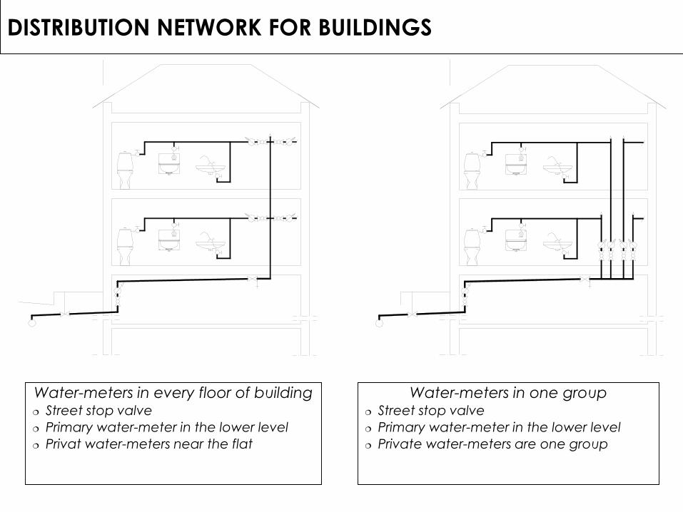
DISTRIBUTION NETWORK FOR BUILDINGS
Water-meters in every floor of building Street stop valve
Primary water-meter in the lower level
Privat water-meters near the flat
Közterület Társasházi tulajdon Társasházi tulajdonKözterület
Water-meters in one group Street stop valve
Primary water-meter in the lower level
Private water-meters are one group

MATERIAL OF PIPES - STEEL PIPES
Pipe with zincked coating and pipe thread
Area of use:
External public network
Fire protection networks (internal
networks of fire hydrants (tüzcsap), in-
built fire extinguishers)
Water network in the building
Advantages:
Fast and simple assembly
High mechanical resistance
Disadvantages:
Low resistance to corrosion, low life time
High need of labour
Higher external diameter due to thehigher wall thickness
Size ( ¼”, ½”, ¾”, 1 ¼”, 1 ½”, 2”, 3”, 4”)
Sealing:
Teflon stripe, tow (kóc)
rubber seals
Corrosion protection (zinc, painting)

MATERIAL OF PIPES PVC PIPE (PVC, CPVC)
1. Area of application: Piping within the building (adhesive, ½” – 4”)
Piping outside the building (husky (tokos) ,Ø90 – Ø450)
2. Advantages: Corrosion resistant
Simple fast assembly with low labour need
3. Disadvantages: High linear thermal expansion factor (0.8
...0.12mm/m°C)
Sensibility to lime (mész) (gypsum mortar orprotection covering)
Life time (mechanical properties decreasewith time, UV radiation, applied temperature)
Leaning to rigidity (at low temperatures)
Not applicable in hot water systems (CPVC!)
Worse mechanical properties
Estimated life time 50 years
4. Connection Adhesive with juntion profiles
Husky, sealing ring
5. Sealing: Athesive
Rubber ring

APPLIANCES - TAPS, VALVES
Taps Only closes and opens of the water flow –
isolating unit
Closing unit is the revolving element positionned in the way of the water-flow
Shape of the revolving element: conical or spherical
Low friction resistance (in opened state the water flows trough without changing direction)
Conical taps Truncated cone (csonkakúp) revolving element Sensitive on pollution Obsolete construction
Ball taps: Most commonly used divisioning unit Rubber sealing between the spheric element and
the cast body Good tightening
Gate valve (Tolózár): Raising spindle, non-rising spindle Only for closing and opening Closing element is flat For higher diameters

APPLIANCES - VALVES
For controling the water-flow
Main elements: Valve head (Szeleptányér) Valve spindle (Szelepszár) Valve bed (Szelepülék)
The closing element movesperpendicularly to the flowing direction.
High aerodynamic resistance
Types:1. Straight valve
Highest direction modification
2. Skew valve
3. Corner valve
Type of intallation: Outlet valve In-built valve
Other types: Mixing valve Mixing valve with one handle
c.)

APPLIANCES – SAFETY DEVICES
Pressure releafe valve (safetyvalve)
Decreases the anecessarily arisedpressure in the system
Pressure Controll valveDecreases the pressure
Non-return (cehck) valveCloses in case of returning flow
air intake valveWater returns to the network
Vent valveRemoves the air from the network
Floating valveKeeps the water level in atmospheric tanks

0 1 2 3 4 5 6 121110 987 13 14 15 181716 23 2422212019 ( h)
qm( l/s )
Filling time Filling time Filling time
Production
Consumption
Consumption
Production
( l/s )mq
19 20 21 22 242316 17 181514137 8 9 10 11 126543210 ( h)
0 1 2 3 4 5 6 121110 987 13 14 15 181716 23 2422212019
qm( l/s )
Consumption Production
DOMESTIC HOT WATER (DHW) - THE DAILY TREND OF WATER DEMAND
Intermittent plant: Social institutions, industrial units Only one consumer
Continuous plant with varying output Residential buildings, hospitals, office buildings
Continuous plant with constant output : Water circulation systems of swimming pools
Necessity of water tanks!

Security valve
Pmax < 8bar
Energy input :
- Electric heating cartridge (P[W])
- Water heat exchanger
One-way valve
M
Termostate
H M HPressure reducing valve
Pmax < 6bar
LOCAL DHW PRODUCTION WITH STORAGE TANK
Energy input
Electric heating cartridge (P[W])
One-way valve
ColdHot
Termostate
Safety
valve
„Filling” and „discharging” plant Lower power need Limited water volume
Atmospheric electric powered hot water tank (5..10 l tank)
Application area: Kitchens, small consumption units for only
one tap.
Disadvantages: Serves only one tap
The tank cannot be under pressure
Advantages: Small size, easy positionning
Simple system
Ideal for local small water need
High pressure closed hot water tank Applicable as electric hot water
producer or indirectly heated tank forflats.
Size: 50..300 l (in case of fixing on thewall static expert needed)
Disadvantages in case of electricheating:
High tied up (lekötött) electric energyneed (2..4kW)
Long heating-up time (4..h)

Security valve
Pmax < 8bar
Energy input
:- Electric heating cartridge (P[W])
- Gas
One-way valve
M H M H
]/[
][][
minl
kWQCCt
V
Production and use at the same time
Main parameters: required heat output (gas, electric power) and water volume (l/min)
Area of application: Kitchens, small consumption units – only
one tap. (~10kW, 5l/min)
Bathrooms, flats with more than one tap (but not at the same time (~25kW, 12l/min)
Disadvantages: High energy need
Limited controlled water flow
Limited temperature control (constant or nearly constant heating power)
Limited distance between production and use (tapping)
Advantages: Easy to fulfil units with low, easy water
need
Small, compact size
LOCAL DHW PRODUCTION WITHOUT WATER STORAGE

Domestic hot water (DHW) - Central DHW production
Supplies one or more buildings
Elements: Heat source, which is usually the
heating boiler or the heat exchanger of a district heating system or independent heat producing unit
Tank with integrated spiral pipe (internal heat exchanger)
Contrl thermostate Security appliances
Metering of consumption
One way valves to stop return flow
Insulation of pipes
Local or central mixing unit at communal buildings (hospital, nursery school, dolmitory, school etc.). Increases the security of service
Circulation pipe
Termosztát

Producement of DHW with solar panel
Main elements
Water storage tank, heat exchanger
Connecting pipe network,
Hydraulic unit
Pump
Expansion wessel
Safety element
Solar panel
Control unit
Temp. sensor of the tank (Thmv)
Temp. Sensor of solar panel (Tk)
Control strategies: , Tk-Thmv>5-10°C
BME Építészmérnöki kar, Épületenergetikai és Épületgépészeti Tanszék
©Szikra Csaba: HMV termelés napkollektorral

N
P
Alarm
sound
Water tank
Pump
Water supply system
Public network
Pressure switch
Temperature sensitive
shower head
Wet
Alarm valve
Protected room
FIRE PROTECTION OF BUILDINGS – SPRINKLER SYSTEM
Wet system:
Above a special temperature the shower head opens. The water flow starts, therefore the pressure decreases in the system. The pump of the water supply system starts to work. The wet alarm valve opens. The shower head waters the fire („k” outflowing factor - kifolyási szám). The alarm valve makes an alarm sound.

(2) Waste Water Systems
Szikra Csaba
Department of Building Energetics and
Services

Equipments - Elements
Waste Water Systems
Quality requirements of an Equipments Economical, adjustable consumption Fulfillment hygienic requirement Clean-ability Architecturality Defending of the abnormal reversed
gas flow
Tap
Border of the
pressurized syetemEquipment
Trap Wast Water
System
Water
Supply
System
Consumption: The place of the consumption is the
equipment
Objective of the equipments: Regulation of the consumption Storing of the water under use Driving the used water into the sewage
water system
Driving force is the gravity: Importance of the slop of the
sewage pipe system: No slope no driving force
high slop, no self cleaning effect
Slop range: 0.7 – 2% The sewage water sped in the pipe
network depending on the slope of the pipe itselvs

Equipments trap
Principles: In the sewage system the chemical
reaction produces gases (like Methane)
In the trap a water piston blocks the reversed flowing sewage gas, avoiding penetration to the residential area
The water piston is keep on changing by the new consumption
Disadvantages: If vacuum occurs in the pipe network, the
water piston could leave the trap
In this case the smelly gases could leave the pipe network penetrating to the residential area
How to avoid: precise design and installation (application of air pipe)
Construction: „S” shaped tube
Hand wash trap
Equipment with inbuilt trap (Toilet, Floor sink etc.)

Equipments - Floor drain
Cast iron drainage grate (old fashion type)
Generally for rooms where escaped water arises (shower, industrial kitchen, etc.)
Main problem is the solution of an adequate joint with the building construction (water proofing)
Suez type trap Floor sink with inbuilt trap Connection for one or two additional
equipment connection (hand wash or shower)
Modern floor sinks: Floor sink with inbuilt trap Connection for additional
equipment(s) Horizontal or vertical outlet connection Inbuilt check valve (against back flush ) DN40, DN50 inlet size Adjustable stainless steel cover
(elevation range 12 – 90mm) Minium space demand 12cm Equipped with water proofing flange
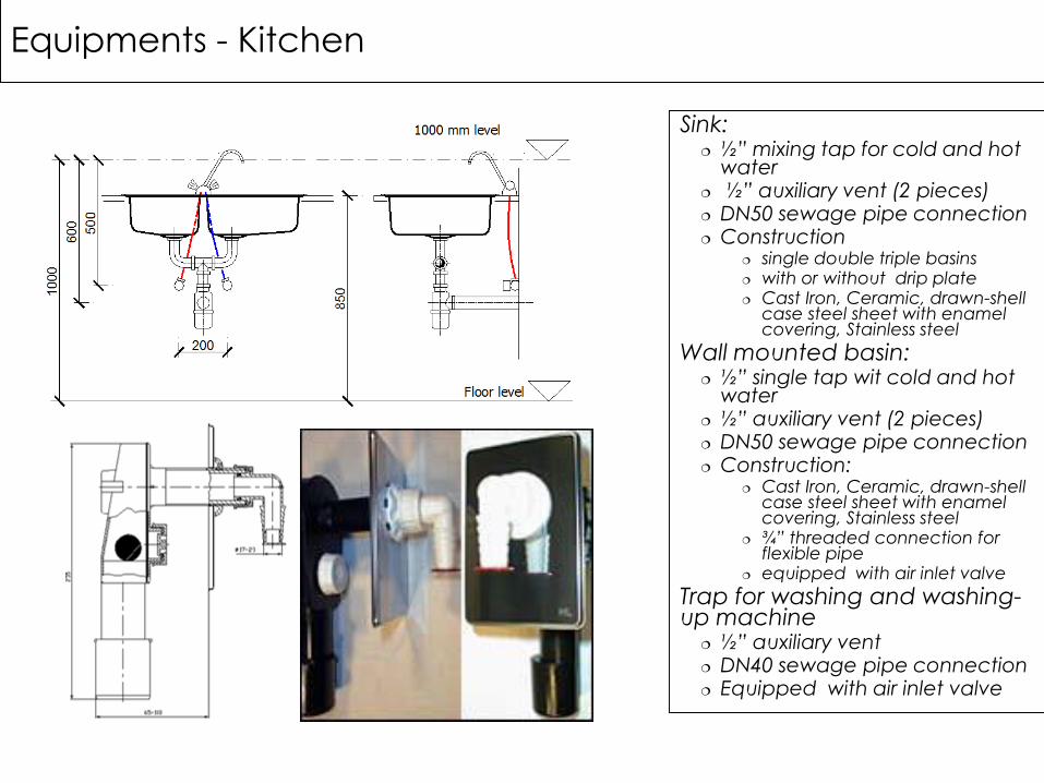
Sink: ½” mixing tap for cold and hot
water ½” auxiliary vent (2 pieces) DN50 sewage pipe connection Construction
single double triple basins with or without drip plate Cast Iron, Ceramic, drawn-shell
case steel sheet with enamel covering, Stainless steel
Wall mounted basin: ½” single tap wit cold and hot
water ½” auxiliary vent (2 pieces) DN50 sewage pipe connection Construction:
Cast Iron, Ceramic, drawn-shell case steel sheet with enamel covering, Stainless steel
¾” threaded connection for flexible pipe
equipped with air inlet valve
Trap for washing and washing-up machine
½” auxiliary vent DN40 sewage pipe connection Equipped with air inlet valve
Equipments - Kitchen
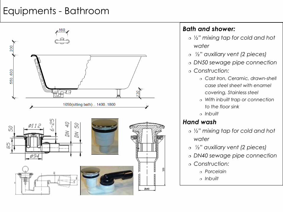
Bath and shower:
½” mixing tap for cold and hot
water
½” auxiliary vent (2 pieces)
DN50 sewage pipe connection
Construction:
Cast Iron, Ceramic, drawn-shell
case steel sheet with enamel
covering, Stainless steel
With inbuilt trap or connection
to the floor sink
Inbuilt
Hand wash
½” mixing tap for cold and hot
water
½” auxiliary vent (2 pieces)
DN40 sewage pipe connection
Construction:
Porcelain
Inbuilt
Equipments - Bathroom
Equipments - Lavatory
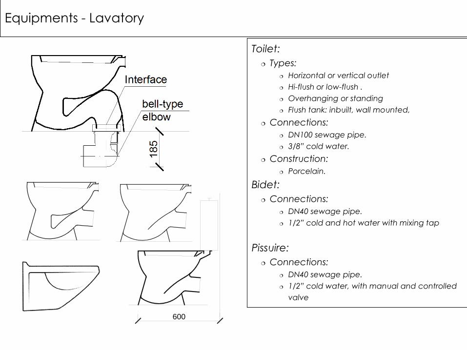
Toilet:
Types:
Horizontal or vertical outlet
Hi-flush or low-flush .
Overhanging or standing
Flush tank: inbuilt, wall mounted,
Connections:
DN100 sewage pipe.
3/8” cold water.
Construction:
Porcelain.
Bidet:
Connections:
DN40 sewage pipe.
1/2” cold and hot water with mixing tap
Pissuire:
Connections:
DN40 sewage pipe.
1/2” cold water, with manual and controlled
valve
600
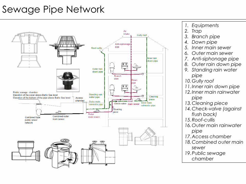
Sewage Pipe Network
1. Equipments2. Trap3. Branch pipe4. Down pipe5. Inner main sewer6. Outer main sewer7. Anti-siphonage pipe8. Outer rain down pipe9. Standing rain water
pipe10.Gully roof11. Inner rain down pipe12. Inner main rainwater
pipe13.Cleaning piece14.Check-valve (against
flush back)15.Roof-cullis16.Outer main rainwater
pipe17.Access chamber18.Combined outer main
sewer19.Public sewage
chamber

When the building is out of the premise border
Inside the sewage and the rain pipe network run separately
Outside around the building in every turning points there are access chambers
At the border of the premise there is a last access chamber in which the two separated pipe network are combined
For the equipment where the elevation is below the elevation of the public sewage chamber, separate collective chamber and sewage pump could be applied
When the building is at the premise border
Inside the sewage and the rain pipe network run separately
Before the sewage and the rain pipe network leave the building it should be combined
Combined public sewage network

Inside the sewage and the rain pipe network run separately
Outside around the building in every turning points there are access chambers
At the border of the premise there are a last access chamber separately for the rain water and for the sewage water system
The rain water domestic network is connected to the public rain water network
The domestic sewage water system is connected to the public sewage water system
It is bent to drive any rain water to the sewage system
Separated public sewage network

If the slop of the pipe network bigger than 5%, the sewage speed too high
The self leaning effect is low
There is an access chamber at the border
We connect the main network with dropping chambers
The maximum slop of the piping is 2%
Pipe network for widely sloping property

In the horizontal section
the sewage water runs in
high speed
At the bend of the
horizontal section high
force could occur
The water piston could
suck the trips
A separate anti-siphonage
pipe should be applied
The anti-siphonage pipe is
connected to the down
pipe in every levels
Systems for high elevation buildings

When the branch pipe turns
to the main down pipe,
because of the fitting shape,
water piston could be
generated.
As the water piston runs
downwards vacuum
generated.
The vacuums could suck
the water from the trap
The sewage gases could
penetrate to the residential
area
Trough the anti-siphonage
pipe the vacuum
development could be
avoided
Function of the anti-siphonage pipe

Pipe material - Outside of the building
Reinforced concrete pipe
Types: Reinforced concrete pipe with, socket
connections, DN100..DN500
Circular and egg shaped cross sections with
grooved connections
Connections, fittings: Access chambers
Light bend
Special fittings
Sealing : cement-mortar
PVC – Plastic pipes with socket connection
Types: KG és KG super types
Connections: Fittings with socket
Access chamber with socket connection
Drilling seats
Sealing: plastic „O” ring

Pipe material
PVC and PP plastic pipe, with
socket connections (PVC KA,PVC
KG, PP):Types
PVC – KG (orange color, better mechanical properties)
PVC –KA (gray)
Connection Fittings with sockets Adhesive connection
Sealing: „O” ring
PE plastic pipe:Connections:
Welded Electro fitting Socket, long socket Union Flange
Advantages Better mechanical properties Environment frendly

Rain water system
Sizing principle:
Design rain intensity: 10 minute
shower density (BP: 274l/s,ha)
q[l/s]=A[m2]×274/10 000
Traditional system:
For each gully roof has its own down
rain pipes
Special sucking system:
special type of gully roof which
generates sucking force
Better efficiency of down flow
smaller diameter
bigger covering area

Mechanical sewage treatment
Button trap:
The sand is heavier than the sewage so it settles to the bottom of the treatment equipment
The purified sewage leaves at the water level
Grease trap:
The lighter parts flooding at the top of the water

Installation method - Groove in the wall
NA50
NA50
1/2"-1/2"
NA50
1/2"
NA100
1/2"
NA40
1/2"-1/2"
NA40
CirkulációMelegvízHidegvízCsatorna
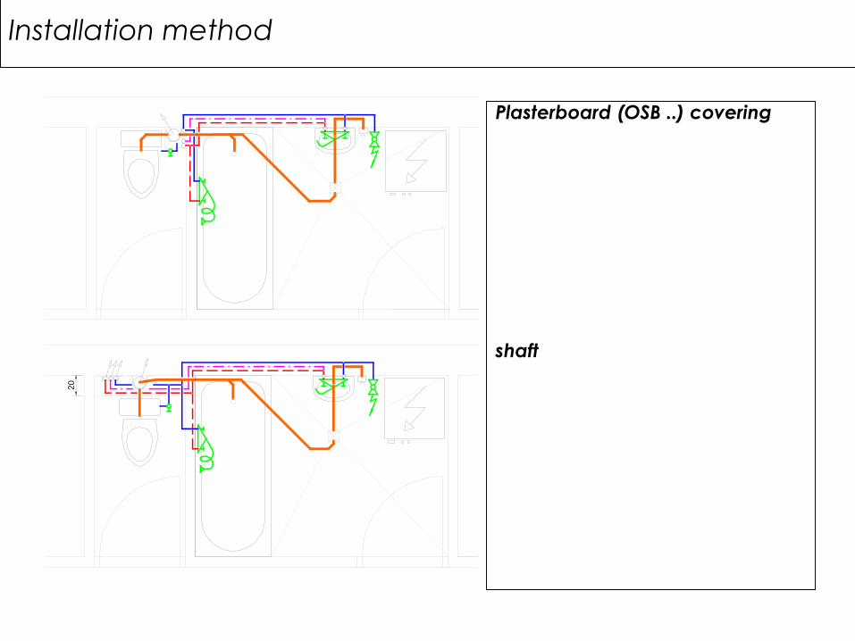
Installation method
Plasterboard (OSB ..) covering
shaftCsatorna Hidegvíz Melegvíz Cirkuláció
Csatorna Hidegvíz Melegvíz Cirkuláció
20
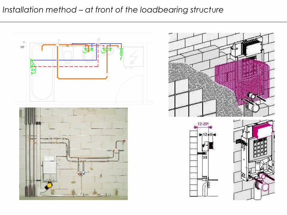
Installation method – at front of the loadbearing structure
Csatorna Hidegvíz Melegvíz Cirkuláció
10

Construction plan - Floorplan, scale 1:50
HL 440
O50x1,8PVC KA
5
HL 301
O50x1,8PVC KA
4
to grand flr.
to grand flr from grand flr.
NA20
PVC KAO50x1,8
O50x1,8PVC KA
O2
2x1
Cu
O2
2x1
Cu
Cu
O1
5x1
O1
5x1
Cu
O1
8x1
Cu
O18x1Cu
Cu
O1
8x1
O22x1Cu
GARDR.
Construction plan - Section scheme and circuit scale:1:50
±0,00 grand floor
+2,95 roof
PVC KG
O110x3
O15x1Cu
O18x1Cu
PVC KAO50x1,8
HL 301
HL-440
DN
15
NA15WILO Z 15 C
DN20
NA15
DN15DN20
O22x1Cu
O110x2,2PVC KA
O110x3
PVC KG
B B C C
O15x1Cu
O15x1Cu
O18x1Cu
PVC KAO50x1,8
PVC KAO50x1,8
O15x1Cu
DN20
CuO22x1
PVC KAO50x1,8
O18x1Cu
O15x1Cu
above the roof
PVC KAO50x1,8
4above the roof
PVC KAO50x1,8
5
O125x3
PVC KGO40x3,7 KPE
-1,30
DN150 protecting tube
to access chamber
O110x3
PVC KG
DN200 protecting tube
O125x3
to access chamber
PVC KG
ff. -0,90
O110x3
PVC KG
Sewgage conduit
Slop, for water network: 0,3%; for sewage conduit: 1%Cold Water
Hot Water
Circulating Pipe
legend
±0,00=113,45 Elevatin above BalticSee
112,55
ff. -0,90
112,55
Risers1 ... 5
O22x1Cu
(3) Gas Supply Systems
Szikra Csaba
Department of Building Energetics and
Services

Gas distribution system Domestic pipe network
Service mains:1. Outside distributor
main2. Interconnecting main3. Inner main distribution
pipe4. Riser 5. Service
connection(from gas meter)
Pressure of the public network:
High pressure(above 25bar)
High intermediate (4 .. 25 bar)
Intermediate (0.1 .. 4 bar)
Pressure of the domestic network
Low pressure (0.01-0.1bar)
Increased low pressure (0.1 bar)
"PIV"
Valve
Outside
distributor main
Interconnecting
pipe
Esta
te b
ord
er
Public Gas
NetworkFloor Level
Inner Main
Distributor Pipe
Max. 1m
Water
Bag
8
00m
m
min
.1
0D
20
01
00
Outside
distributor main
Public Gas
Network
Esta
te b
ord
er
"PIV"
Valve
Interconnecting
pipe
Floor Level200
min
1000x800
min
200
40
0
min

Service connection
(from gas meter):
1. Gas meter
Nominal gas
consumption
Curb cock (main
cock)
Water bag
2. Equipments
Kitchen stove
Boilers
Auxiliary gas cocks
3. Flue Gas
Chimney
Draft diverter
Chimney BodyInterconnecting pipe
Service connections
ChimneyBoylerKitchen stove
Esta
te b
ord
er 20
0
16
00
70
0
Gas meter
±0,00
steel1"
steel1"
11
00
12
00
Construction plan – Elevation circuit, Domestic pipe network

Gas MetersRules of Placement of meters in domestic level
It is possible to place gas meter with keeping a following circumstances
Outside and outside walls → Mechanical protection and temperature correction
In staircase, common rooms → Closed and ventilated cabinet
In basement
Non corrosive,
waterproofing, plastering
min 1.7m elevation,
Gas meter can not be placed:
In bathroom, in toilet
In living areas (Dining room, sleeping rooms etc.)
In garage,
Switch gear rooms or cabinets where voltage higher than 0.4kV
Rooms which classified in A or B fire class
In boiler rooms
Safety distances:
From any gas equipments: 1m
Any hot pipe, ducks etc: 0.5m

Space demand:
Single Meter
Interconnecting pipe
always from left
Service connection
always from right
Closing valve in both
side above 6m3/h
Ventilatable,
lockable cabinet
Multi Meter place
Water jacket
Nominal size in
domestic level
G4,G6 (m3/h)
Size: 30×24×10 (cm)
Connection:1” – 1”,
25cm
GAS METERS - PLACEMENT OF METERS IN DOMESTIC LEVEL
500
60
0
Interconnecting pipe
network:
Service
connection
25
0
12
00
..1
70
0
20
0
900
Interconnecting pipe
network:
1600
250
1000
1200

CLASSIFICATION OF EQUIPMENTS
Class: Name Supplied air: Flue gas: Example:Most important circumstances:
AWith open
combustion chamber
From the internal areal
to the internal
area
Kitchen stoveWater heater,
Infra red heater
above 5230W with openings
Aopening. ≥ 1.3m2
hl ≤ 590 W/m3
B
Connected to a
chimney (Closed burning
chamber)
From the internal area
To the external
area
Wall mounted water heaterWall mounted
heater,Boiler.
hl ≤ 3140 W/m3
Aopening. ≥ 1.3m2
CWith closed combustion
chamber
From the external area
To the external
area
Wall mounted gas convector
unit,Wall mounted water heater,
Boiler.
Double coated chimney body (for air and for the
flue gas)

Safety valve
Supplied air
Draft diverter
Minimum water
flow rate sensor
Temperature
max. sensor Burner
Pilot flameFlame monitor
Gas continuity
sensor
Cold Water
Hot water
Water heaters without storage capacity
Class „A”(smaller instruments), ”B”
Types:
Smaller instrument for serving only
one tap Nominal heat capacity:~10kW,
Produced hot water: 5~6l/min
Bigger instrument for serving more
than one taps → Wall mounted
water heaters (Class „B”) Nominal heat capacity :18~28kW
Produced hot water: 7~14l/perc
Disadvantages:
Ones jus only serving one tap
Does not work with circulating pipe
Constant heat capacity
Safety equipments:
Temperature maximum sensor
Gas discontinuity sensor
Pilot flame with flame monitor
Water minimum flow rate sensor
Safety valve
Draft diverter

WALL MOUNTED BOILERS
Class: „B”, „C”
Types:
Only for heating:
Produced heat capacity:~10..40kW;
Inbuilt pump;
Inbuilt expansion tank;
Regulated by the minimum water flow
rate sensor.
Combined for heating and producing
domestic hot water :
Produced heat capacity :18~28kW;
Guided for DHW production;
Produced hot water : 7~14l/perc.
Disadvantages:
disadvantages of wall mounted water
heaters;
During DHW producement heating is
stopped
Safety equipments:
Wall mounted water heaters
equipped with inbuilt closed expansion
tank
Main return
Main flow
Closed
expansion
tank
Pump
Supplied air

WALL MOUNTED BOILER WITH INDIRECTLY HEATED WATER STORAGE
Control:
Temperature sensor
Switch valve
Guided for DHW
production;
Advantages:
Smaller necessary heat
capacity
Continuously served hot
water with uniform
temperature
Suitable for circulating
network
Domestic board sizes:
Nominal heat
capacity10 .. 28kW
Storage capacity: 50 ..
200l
Hot water
storage
Boiler
Switch
valve
Bypass
valve
Temperature
sensor
Heat emiter
Heat
exchanger

WALL MOUNTED HEAT CONVECTOR UNIT
Class „C”
Advantages:
Safe;
Sort heating up period;
Simple ;
Disadvantages:
Hot surfaces
Horizontal chimney
connection
Parapet chimney
Bad efficiency
Class „B”
Supplied air
Secondaty air
(convective flow)
Flue gas
Chimney
Flue gas
Secondary air
(Convective heat)