plug nozzle
DESCRIPTION
Nozzle theoryTRANSCRIPT

RTO-TR-AVT-007-V1 1
PLUG NOZZLES: SUMMARY OF FLOW FEATURES AND ENGINE PERFORMANCE
Marcello Onofri University of Rome “La Sapienza”, Roma, Italy Chairperson of RTO/AVT WG 10 – Subgroup 1
The text is provided, as originally formatted, on the following pages.

(c)2002 American Institute of Aeronautics & Astronautics or Published with Permission of Author(s) and/or Author(s)' Sponsoring Organization.
AIAA 2002-0584
PLUG NOZZLES: SUMMARY OF FLOWFEATURES AND ENGINE PERFORMANCE
Overview of RTO/AVT WG 10 Subgroup 1
Marcello OnofriUniversity of Rome "La Sapienza ", Roma, ItalyChairperson ofRTO/A VT WG 10 - Subgroup 1
Contributions by:
M.. Calabro, EADS-LV, Les Mureaux, FranceG.. Hagemann, H.Immich and P. Sacher, Astrium GmbH, Munich, Germany
M. Onofri and F. Nasuti, University of Rome "La Sapienza", Roma, ItalyP. Reijasse, ONERA, Meudon, France
ABSTRACT
This paper represents an overview of the activitiescarried out in the framework of RTO/AVT WorkingGroup 10, Subgroup 1, dedicated to plug nozzleaerothermodynamics and performance. The subgroupworked out two main objectives: i) thoroughunderstanding of the flow physics of plug nozzlestrough literature review and recent experimentsconducted in Europe and USA; ii) definition of CFDtest cases, conduction of CFD calculations andcomparison with experimental data. This papersummarizes the findings of the flow physics based onliterature review and recent experiments. It is the resultof the many interesting discussions promoted by allmembers participating to the subgroup, whosecontribution is acknowledged by the authors. Inparticular, the following key topics are discussed indepth in the paper:- Survey on Past AGARD Activities.- The Fundamental Aspects of Plug Nozzle Flowfields.- The Wake Structure Transition from Open to Closed.- The Influence of the External Flow.- Plug Nozzle Base Pressure versus Flight Altitude.- Altitude Adaptive Character of Plug Nozzles with
Regard to Performance.- Contour Design Methods.- Aerospike: Thrust Vector Control.
CFMP
NOMENCLATURE
Thrust CoefficientMach numberStatic Pressure
* Professor, Dipartimento di Meccanica e Aeronautica, ViaEudossiana 18, Roma 00184, Italy, Senior Member,marcello.onofri@uniromal .itCopyright ©2002 The American Institute of Aeronautics andAstronautics Inc. All rights Reserved.
PoPRruxP
8
e9Y
Total PressureNozzle Pressure Ratio (pc/pa)Distance from the simmetry axisVelocityDistance along the axisMach line angle (characteristicwave, positive clockwise); andthrust deflection angleArea ratioFlow turning anglePlug exit angleRatio of specific heatsEfficiency (CF/CFii)
Subscripts
1oo —
a =bc =d,De =iintPs =tr
1.
Primary Nozzle exit sectionFree-streamAmbientBaseChamberDesignNozzle exitIdealInternalPlugShroudOpen/Closed wake transition
SURVEY ON PAST AGARDACTIVITIES
prepared byP. SacherAstrium GmbH, Space Infrastructure Propulsion,Munich, Germany.
The problem of optimizing the afterbody nozzleintegration for airbreathing propelled vehicles has beena long time subject of special dedicated efforts within
American Institute of Aeronautics and Astronautics
2 RTO-TR-AVT-007-V1
(c)2002 American Institute of Aeronautics & Astronautics or Published with Permission of Author(s) and/or Author(s)' Sponsoring Organization.
the AGARD technical programs. In view of the neweffort of creating again a working group to review thepresent status of the art and to explore progress havingbeen made since previous activities related to afterbodynozzle and external flow interaction and nozzleafterbody integration, it is worthwhile to shortlysummarize at the beginning of this exercise theobjectives and the major outcome of the past activities.
In 1972 AGARD initiated a multinational program onimproved nozzle testing, the WG 04, in which nineorganizations from five nations participated. For a firstcomparative study, three axisymmetric afterbodynozzle configurations were defined with boattail anglesof 10°, 15° and 25° respectively with one internalconvergent nozzle contour. The work done was purelyexperimental the tests covered the Mach number rangefrom 0.6 to 0.95 (1.5) and nozzle pressure ratios of 1 to7 (15). A major emphasis was given to identify theinfluence of different test facilities and different modelsupport systems on the boattail pressure distribution.The Results obtained are very well documented in Ref.[1]. Conclusions and recommendations for nextactivities were:
1. to investigate the effects of exhaust temperature,2. to redefine and extend analytical procedures to
cases with shock wave boundary layer interactions,3 to develop the use of computational procedures to
assess wind-tunnel wall interference and4. to perform a refinement in wind tunnel calibrations.
In 1984 it was timely to review in a new AGARD WG-08 the progress achieved. Since AGARD has publishedthe results of the WG-04, both wind tunnel techniqueshad been improved considerably and computationalfluid dynamics for drag evaluation and prediction ofpressure distributions has reached the status of practicalapplicability for axisymmetric nozzles even withhighly viscous dominated or even partially separatedafterbody transonic flow. This new working groupassessed specifically2:
a), with regard to computational methods- the status of in viscid methods including jet
effects,- the status of methods for afterbody flow
computations including viscous effects (bothjet/free stream mixing and boundary layer)
- the status of solutions of the full or thin-layerparabolized Navier-Stokes equations
- the critical range and accuracy of availablemethods with respect to afterbody dragprediction.
b). with regard to experimental methods- afterbody testing and testing results since 1975,
with special attention to drag/thrust evaluation,
- progress in afterbody testing achieved withconventional jet simulation and with turbinepowered simulation (TPS),
- Analysis of wind tunnel test techniques,- methods to detect flow instabilities and
unsteady boundary-layer separation effectsincluding afterbody buffeting and
- wind tunnel correction methods for afterbodytests.
Thirteen test cases were identified. The prime criterionfor selection was the availability of extensiveexperimental measurements of surface pressure andflow field characteristics. Eight of the test cases weretypical airplane-type nozzle configurations and theremaining five were typical missile afterbodyconfigurations. In all cases, the jet exhaust wassimulated with high-pressure air. Cases were selectedto show the effects of nozzle geometry, nozzle pressureratio, free-stream Mach number, jet exhausttemperature and wind tunnel blockage. All test casesused for CFD comparisons were limited toaxisymmetric configurations at zero degree angle ofattack.
The general conclusion at the end of the secondAGARD WG was that the experimental techniques hadreached a very high level of reliability if propercorrection procedures are applied and error analysis isperformed as recommended. In the area of CFD is wasstated, that research and development had reached thelevel of applicability for simple (single jet) geometryusing viscous/inviscid interaction methods or solutionsof the Navier-Stokes equations. Both, experimentaltechniques and CFD are understood now as beingcomplementary tools for the design of optimalafterbody shapes.
In 1992, one decade later, AGARD again felt again itstime to provide an update and to review once more thestate-of-the-art, now with particular consideration ofthe progress made on the computational simulation ofthree-dimensional viscous flow. The specific objectivesofAGARDWG17,were3:
1. to study 3D aspects of aircraft afterbodyintegration, that is, at angle of attack, at non-axisymmetric afterbodies and at twin jetconfigurations,
2. to evaluate present experimental methods andrecommend additional techniques as appropriate,
3. to collect databases in order to understand flowphysics and to validate computational tools and
4. to calculate 3D afterbody flows to assess the state-of-the-art and to recommended advancements.
WG-17 was organized in two groups, the first,concentrating on the understanding and simulation ofthe "Fundamental Flow Phenomena" and the second,addressing the wider practicalities of applying such
American Institute of Aeronautics and Astronautics
RTO-TR-AVT-007-V1 3
(c)2002 American Institute of Aeronautics & Astronautics or Published with Permission of Author(s) and/or Author(s)' Sponsoring Organization.
simulations to highly complex geometries typical foradvanced fighter aircraft during "Design andEngineering Work".
Group 1: Fundamental Flow PhenomenaThree test cases have been selected to constitute adatabase allowing an in depth validation of advancedcomputer codes on basic configurations reproducingtypical afterbody flow situations. Only threedimenionalconfigurations and cases with hot gas simulations wereconsidered, the cold jet case being only retained forreference. For all test cases detailed flow field datawere available without restrictions:A.I Axisymmetric body without jet at incidence 5° atMach=0.54;A.2 Axisymmetric body with cold/hot jet at Mach=0.8and jet expansion ratio of 4.8;A.3 Twin jet with cold flow at Mach=0.8/0.85 and jetexpansion ratio of 5.Numerical results obtained from Navier-Stokessimulations by seven different organizations andcomparisons with experimental data were providedonly for testcase A.2.
Group 2: Design and Engineering WorkSemi-empirical and CFD design methods were appliedand experimental data were provided for four test cases(each with variants) covering as major variables freestream Mach number, nozzle pressure ratio, aftendshape, tail position and single and twin engines withand without boundary layer separation at theafterbody/nozzle configuration.B.I. NASA Langley single engine afterbody without
tails at Mach=0.9 and PRs =2/5;B.2. NASA Langley single engine afterbody with two
different tails at Mach-0.9 and PRs -2/3/5;B.3 NASA Langley twin engine afterbody with three
different tails at Mach=0.9 and PR=3.4;B.4. NASA Langley 2-D convergent-divergent single
isolated nozzle at Mach=0.6 and 0.94 andPR=4.0.
Numerical results obtained from 14 differentorganizations are compared with the experimental datamostly with regard to surface pressure distributions anddrag coefficients. Recommendations are given forfuture work.
2. THE FUNDAMENTAL ASPECTS OFPLUG NOZZLE FLOWFIELDS
prepared byMarcello Onofri and Francesco NasutiUniversity of Rome "La Sapienza ", Rome, Italy
The plug nozzle is an expansion device including aprimary nozzle, whose shape can be quiteconventional, and a spike or plug yielding an externalexpansion. One of the main properties of these nozzlesis their peculiar interaction with the external ambient,
that is able to avoid the flow separation phenomenathat affect conventional bell nozzels. In this sense a keyrole is played by the expansion fan generated at theprimary nozzle lip and on its effect on the pressurebehavior along the plug wall. The followingcontribution analyzes this phenomenon by examplesaiming to show the fundamental nozzle behavior. Idealplug nozzle behavior is analyzed first, with theassumption of full length plug, inviscid gas. quiescentair and plug profile designed as such to provide parallelflow at the design operating condition with axial flowat the plug exit. Maintaining the same assumptions, theanalysis is continued for nozzles different than ideal,featuring more practical internal expansions. Finally,some aspects of plug truncation are also discussed.
FULL LENGTH IDEAL PLUG
The analysis of full-length plug configurations is agood reference to evaluate the performance oftruncated plug nozzles whose design is based on thesame plug geometry. The case here reported features alinear plug nozzle with a sonic orifice as a primarynozzle4'5, exhausting over an ideal contour plugdesigned following the Angelino's method6; the designnozzle pressure ratio is PR=200, where PR indicateschamber to ambient pressure ratio.
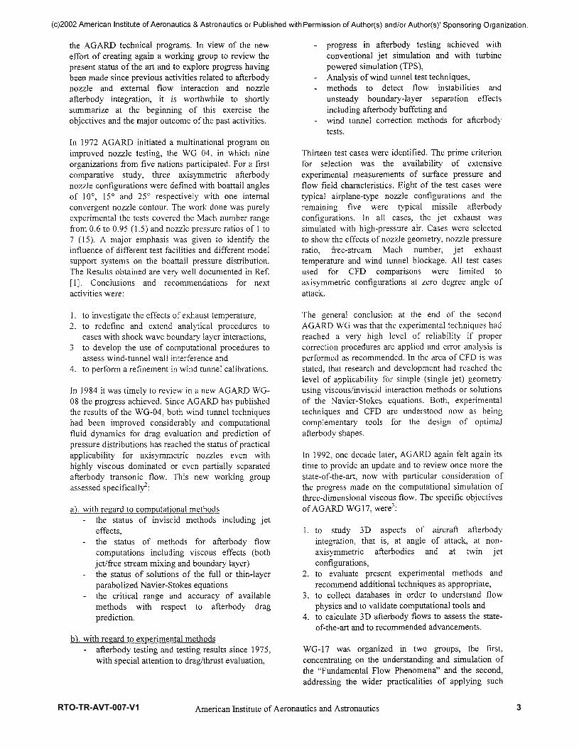
The inviscid solution at design condition (PR=200) isshown by Mach number contours in Fig. 2.la. Becauseof the interaction with the lower pressure ambient, theexhaust jet undergoes a centered expansion at theprimary nozzle lip, and rotates up to the axial direction.The reflected expansion waves are canceled out by thesuitable design of the plug geometry, and eventuallyuniform axial flow is obtained at the plug exit. Thecorresponding computed wall pressure is a monotonicdecreasing function (Fig.2.2). The profile of the jetboundary is a straight line parallel to the x-axis, astheoretically expected from the plug design. Inpractice, the nozzle behaves like an ideal nozzledesigned for the same PR, for both design andunderexpanded conditions. Indeed, it is easy to inferthat when the ambient pressure falls below the designconditions, the further expansion at the primary nozzlelip yields no effect on the plug. Thus, inunderexpanded conditions, the thrust increases onlybecause of the pressure thrust term, like inconventional underexpanded nozzles, whereas theimpulse thrust term remains unchanged.
The advantages of plug nozzles are shown, on thecontrary, by its adaptation capability in overexpandedconditions, that makes plug nozzles suitable to achievevery high expansion ratios at altitude.
In fact, when ambient pressure is higher than thedesign value, the nozzle behavior is again driven by theexpansion at the primary nozzle lip. In particular, theexhaust flow undergoes a weaker centered expansion at
3American Institute of Aeronautics and Astronautics
4 RTO-TR-AVT-007-V1

(c)2002 American Institute of Aeronautics & Astronautics or Published with Permission of Author(s) and/or Author(s)' Sponsoring Organization.
the primary nozzle lip, and turns less than in designconditions. Therefore, the last expansion waveimpinges on the plug wall at shorter and shorterdistance from the primary nozzle exhaust section (Fig.2.1b-h). Downstream of the last expansion wave, theplug geometry, designed such as to avoid the reflectionof the other expansion waves occurring for PR=200,generates compression waves. They interact with thejet boundary, yielding its rotation, as shown inFig.2.1c-h. The result of the interaction of thecompression waves with the constant pressure jetboundary is a second centered expansion fan, whichmakes the flow expands again downstream, where thewhole cycle can be repeated. As ambient pressurefurther increases the expansion at the primary nozzlelip (Fig.2.1c-d) reduces accordingly, leaving larger andlarger part of the plug to the expansion-compression,having smaller and smaller amplitude (Fig.2.2).
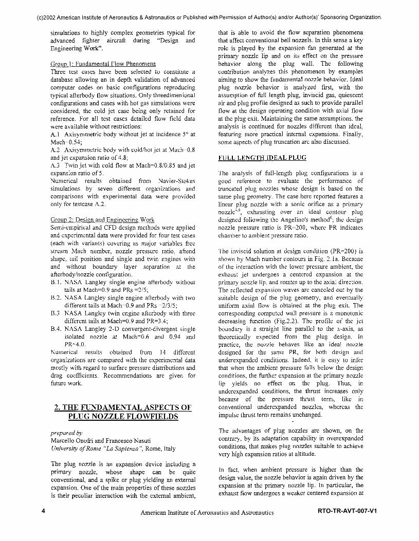
The self-adaptation process is indicated by the flow atthe plug exit section, displaying nearly axial direction,and average pressure nearly equal to the ambientpressure. This behavior is also confirmed by the values,shown in Fig. 2.3, of the nozzle efficiency TJ, defined as
the ratio of the thrust coefficient (CF) to the idealthrust coefficient (CF)i). The CF,i is the maximumtheoretical CF achievable at an assigned pressure ratio,computed by one-dimensional (ID) relations (idealadapted nozzle).
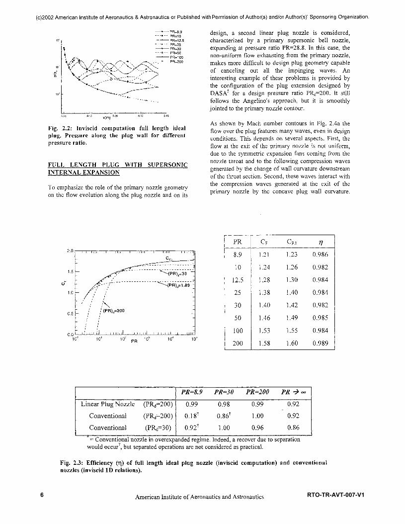
The computed efficiency is high in both on-design andoff-design conditions, and its displacement from 1.0 isof the same order of the numerical accuracy of thecomputations for the whole range of pressure ratiosexplored. As reference values, Fig. 2.3 shows also theefficiency of conventional nozzles designed for thepressure ratio PR^, computed by ID relations. Thesevalues allow quantifying the advantages of a self-adaptable nozzle. One of its well-known properties isto show, for the operations at the lower PRs, betterefficiency than a conventional nozzle designed for thesame PR^, even without accounting for the well-knowntroubles of a conventional nozzle in highly-overexpanded conditions. Another is to show, for theoperations at the higher PRs, higher efficiency than aconventional nozzle designed for lower PR<i.
PR=200____Mach Number (AM=0.1)
0.000.00 0.05 0.10 0.15 0.20 0.25 0.30 0.35 x(m)
a)
PR=100 Mach Number (AM=0.1)E>;
0.00^0.00 0.05 0.10 0.15 0.20 0.25 0.30 0.35 x(m)
b)
0.00
PR=50 Mach Number (AM=0.1)
0.00 0.05 0.10 0.15 0.20 0.25 0.30 0.35 x(m)
PR=30 Mach Number (AM=0.1)
0.00 0.05 0.10 0.15 0.20 0.25 0.30 0.35 x(m)
d)
0.10
0.05
0.00
Mach Number (AM=0.1)
0.00 0.05 0.10 0.15 0.20 0.25 0.30 0.35 x(m)
e)
0.10 -E>:
PR=12.5 Mach Number (AM=0.1)
0.00 0.05 0.10 0.15 0.20 0.25 0.30 0.35 x(m)
0
JX10£
0.05
0.00
PR=10 Mach Number (AM=0.1)
0.00 0.05 0.10 0.15 0.20 0.25 0.30 0.35 x(m)
g)
0.10§
0.05
0.00
PR=8.9 Mach Number (AM=0.1)
0.00 0.05 0.10 0.15 0.20 0.25 0.30 0.35 x(m)
Fig. 2.1: Inviscid computation of full length ideal pIug.Mach number contours for differentpressure ratios: a) PR=200; b) PR=100; c) PR=50; d) PR=30; e) PR=25; f) PR=12.5; g) PR=10; andh) PR=8.9 4.
4American Institute of Aeronautics and Astronautics
RTO-TR-AVT-007-V1 5
(c)2002 American Institute of Aeronautics & Astronautics or Published with Permission of Author(s) and/or Author(s)' Sponsoring Organization.
——•—— PR=8.9— - - » - - PR=10——'——PR=12.5—--• - - •PR=25——•—— PR=30—--»- - -PR=50——"——PR=100
,"-»---PR=200
x(m)
Fig. 2.2: Inviscid computation full length idealplug. Pressure along the plug wall for differentpressure ratio.
FULL LENGTH PLUG WITH SUPERSONICINTERNAL EXPANSION
To emphasize the role of the primary nozzle geometryon the flow evolution along the plug nozzle and on its
design, a second linear plug nozzle is considered,characterized by a primary supersonic bell nozzle,expanding at pressure ratio PR=28.8. In this case, thenon-uniform flow exhausting from the primary nozzle,makes more difficult to design plug geometry capableof canceling out all the impinging waves. Aninteresting example of these problems is provided bythe configuration of the plug extension designed byDAS A5 for a design pressure ratio PR^OO. It stillfollows the Angelino's approach, but it is smoothlyjointed to the primary nozzle contour.
As shown by Mach number contours in Fig. 2.4a theflow over the plug features many waves, even in designconditions. This depends on several aspects. First, theflow at the exit of the primary nozzle is not uniform,due to the symmetric expansion fans coming from thenozzle throat and to the following compression wavesgenerated by the change of wall curvature downstreamof the throat section. Second, these waves interact withthe compression waves generated at the exit of theprimary nozzle by the concave plug wall curvature.
10* pR 103 10b
PR
8.9
10
12.5
25
30
50
100
200
CF
1.21
1.24
1.28
1.38
1.40
1.46
1.53
1.58
CF,,
1.23
1.26
1.30
1.40
1.42
1.49
1.55
1.60
?70.986
0.982
0.984
0.984
0.982
0.985
0.984
0.989
Linear Plug NozzleConventional
Conventional
(PRd=200)
(PRd=200)(PRd=30)
PR=8.9
0.990.181
0.92f
PR=300.980.861
1.00
PR=200
0.991.00
0.96
PR ->°o0.920.92
0.86= Conventional nozzle in overexpanded regime. Indeed, a recover due to separation
would occur7, but separated operations are not considered as practical.
Fig. 2.3: Efficiency (T|) of full length ideal plug nozzle (inviscid computation) and conventionalnozzles (inviscid ID relations).
American Institute of Aeronautics and Astronautics
6 RTO-TR-AVT-007-V1
(c)2002 American Institute of Aeronautics & Astronautics or Published with Permission of Author(s) and/or Author(s)' Sponsoring Organization.
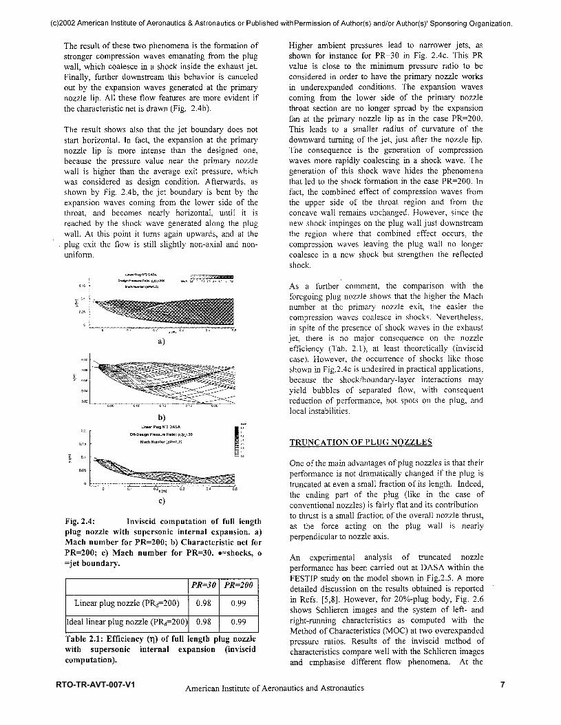
The result of these two phenomena is the formation ofstronger compression waves emanating from the plugwall, which coalesce in a shock inside the exhaust jet.Finally, further downstream this behavior is canceledout by the expansion waves generated at the primarynozzle lip. All these flow features are more evident ifthe characteristic net is drawn (Fig. 2.4b).
The result shows also that the jet boundary does notstart horizontal. In fact, the expansion at the primarynozzle lip is more intense than the designed one,because the pressure value near the primary nozzlewall is higher than the average exit pressure, whichwas considered as design condition. Afterwards, asshown by Fig. 2.4b, the jet boundary is bent by theexpansion waves coming from the lower side of thethroat, and becomes nearly horizontal, until it isreached by the shock wave generated along the plugwall. At this point it turns again upwards, and at theplug exit the flow is still slightly non-axial and non-uniform.
a)
b)Linear Plug N'2 DASA
Off-Design Pressure Ratio: pc/p.=30
Mach Number (AM=0.2)
Fig. 2.4: Inviscid computation of full lengthplug nozzle with supersonic internal expansion, a)Mach number for PR=200; b) Characteristic net forPR=200; c) Mach number for PR=30. ^shocks, o=jet boundary.
Linear plug nozzle (PR<f=200)
Ideal linear plug nozzle (PR^=200)
PR=30
0.98
0.98
PR=200
0.99
0.99
Table 2.1: Efficiency (T|) of full length plug nozzlewith supersonic internal expansion (inviscidcomputation).
Higher ambient pressures lead to narrower jets, asshown for instance for PR=30 in Fig. 2.4c. This PRvalue is close to the minimum pressure ratio to beconsidered in order to have the primary nozzle worksin underexpanded conditions. The expansion wavescoming from the lower side of the primary nozzlethroat section are no longer spread by the expansionfan at the primary nozzle lip as in the case PR=200.This leads to a smaller radius of curvature of thedownward turning of the jet, just after the nozzle lip.The consequence is the generation of compressionwaves more rapidly coalescing in a shock wave. Thegeneration of this shock wave hides the phenomenathat led to the shock formation in the case PR=200. Infact, the combined effect of compression waves fromthe upper side of the throat region and from theconcave wall remains unchanged. However, since thenew shock impinges on the plug wall just downstreamthe region where that combined effect occurs, thecompression waves leaving the plug wall no longercoalesce in a new shock but strengthen the reflectedshock.
As a further comment, the comparison with theforegoing plug nozzle shows that the higher the Machnumber at the primary nozzle exit, the easier thecompression waves coalesce in shocks. Nevertheless,in spite of the presence of shock waves in the exhaustjet, there is no major consequence on the nozzleefficiency (Tab. 2.1), at least theoretically (inviscidcase). However, the occurrence of shocks like thoseshown in Fig.2.4c is undesired in practical applications,because the shock/boundary-layer interactions mayyield bubbles of separated flow, with consequentreduction of performance, hot spots on the plug, andlocal instabilities.
TRUNCATION OF PLUG NOZZLES
One of the main advantages of plug nozzles is that theirperformance is not dramatically changed if the plug istruncated at even a small fraction of its length. Indeed,the ending part of the plug (like in the case ofconventional nozzles) is fairly flat and its contributionto thrust is a small fraction of the overall nozzle thrust,as the force acting on the plug wall is nearlyperpendicular to nozzle axis.
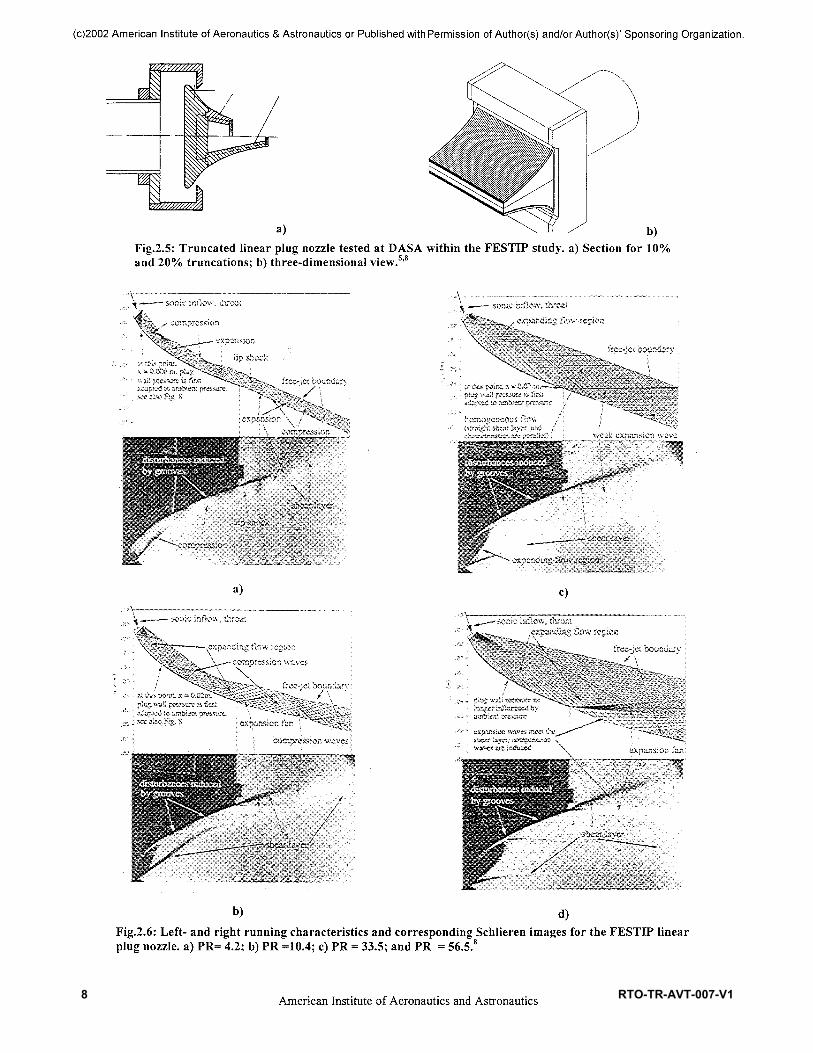
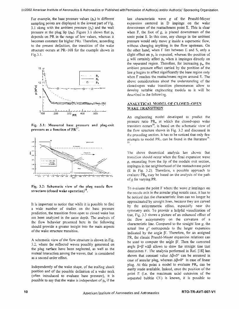
An experimental analysis of truncated nozzleperformance has been carried out at DASA within theFESTIP study on the model shown in Fig.2.5. A moredetailed discussion on the results obtained is reportedin Refs. [5,8]. However, for 20%-plug body, Fig. 2.6shows Schlieren images and the system of left- andright-running characteristics as computed with theMethod of Characteristics (MOC) at two overexpandedpressure ratios. Results of the inviscid method ofcharacteristics compare well with the Schlieren imagesand emphasise different flow phenomena. At the
American Institute of Aeronautics and Astronautics
RTO-TR-AVT-007-V1 7
(c)2002 American Institute of Aeronautics & Astronautics or Published with Permission of Author(s) and/or Author(s)' Sponsoring Organization.
a) \ I I / b)Fig.2.5: Truncated linear plug nozzle tested at DASA within the FESTIP study, a) Section for 10%and 20% truncations; b) three-dimensional view.5'8
a)
^;s»altti.Hg.
........... J^^^^^:^^,^
"" ""'""" '" l ^^ ira^fctttt®^^^^
b)
c)
d)Fig.2.6: Left- and right running characteristics and corresponding Schlieren images for the FESTIP linearplug nozzle, a) PR= 4.2; b) PR =10.4; c) PR = 33.5; and PR = 56.5.8
American Institute of Aeronautics and Astronautics
8 RTO-TR-AVT-007-V1

(c)2002 American Institute of Aeronautics & Astronautics or Published with Permission of Author(s) and/or Author(s)' Sponsoring Organization.
10 % Length (inviscid)PR30
200
CF
1.071.52
CF,,1.421.60
T!0.760.95
20 % Length (inviscid)PR8.9102030100200
CF
1.091.121.121.211.461.55
CF,1.231.261.371.421.551.60
T!0.890.890.820.850.940.97
20 % Length (viscous)PR8.920
CF
1.091.23
CF,,1.231.37
t\0.890.89
- - •*- - - LPN1-10 (Inviscid)- - -O- - - LPN1-20 (Inviscid)- - - • — - LPN1-20 (Viscous)- - -a- - - LPN1-100(Inviscid)
100% Length: r|=0.98-0.99
Figure 2.7: Efficiency (T|) of plug nozzles truncated at different lengths, as obtained by viscous and inviscidsimulations. The value of CF is split in the contributions of primary nozzle, plug and base in the plot.
lowest pressure ratio PR=4.2 (Fig. 2.6a), a lip shock iscentred at the end of the plug body, because the basepressure is higher than the upstream wall pressure. Atthe pressure ratio PR=10.4 (Fig. 2.6b), upstream wallpressures are higher than the base pressure, and anexpansion fan accelerates the flow to the base pressure.At the intermediate pressure ratio PR=33.5 (Fig.2.6c),the plug end wall pressure and ambient pressure arealmost equal, and only a very weak expansion isobserved. Therefore, the lower shear layer separatingthe base flow and the supersonic exhaust flow hasalmost the same slope as the contour at its truncation.Thus, the formation of an expansion wave or a lipshock at the end tip strongly depends on the pressuredifference between upstream wall pressure and basepressure.
Some results of the analysis performed by both inviscidand viscous calculations on early truncation (10% and20%) of the plug nozzles discussed in the foregoingsection are summarized in Fig. 2.7. They allow aqualitative analysis of the performance, showing alsothat the base contribution to thrust ranges from a smalldrag or a neutral contribution in the overexpandedregime, to positive values at higher PR.
3. THE WAKE STRUCTURE TRANSITIONFROM OPEN TO CLOSED
prepared byMarcello Onofri and Francesco NasutiUniversity of Rome "La Sapienza", Rome, Italy
The understanding of the mechanism of transition fromopen to closed wake in the region behind the truncatedbase is important for the applications of plug nozzles.Indeed, its knowledge allows the prediction of thetransition, from negative to positive, of the contributionof the plug base pressure to the nozzle thrust, andconsequently of the nozzle performance along theflight trajectory.
Many experimental and theoretical studies have beenperformed on the flow evolution behind truncatedplugs or more generally behind backward-facing steps.Among them, it is worth to remind the analyses of plugnozzles performed by Sule and Mueller11, thetheoretical considerations about the flow rotation inbase regions performed by Weiss and Weinbaum12, andfinally the large number of recent numerical analyseson the backward-facing step problem13"16.
From the many visualizations reported in those studiesit can be noted that there is no clear definition of thetransition point between the two wake structures.Therefore, it is useful to establish a definition based ona practical aspect, considering the pressure value thattakes place on the base:
• open wake: is the flow structure featuring a basepressure depending on the ambient pressure;
• closed wake: is the flow structure featuring a basepressure independent of the ambient pressure.
American Institute of Aeronautics and Astronautics
RTO-TR-AVT-007-V1 9
(c)2002 American Institute of Aeronautics & Astronautics or Published with Permission of Author(s) and/or Author(s)' Sponsoring Organization.
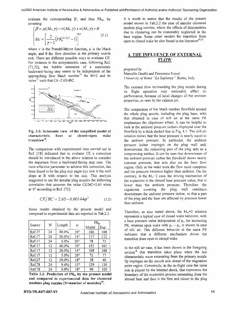
For example, the base pressure values (pb) in differentsampling points are displayed in the lowest part of Fig.3.1 along with the ambient pressure (pa) and the wallpressure at the plug lip (pB). Figure 3.1 shows that pbdepends on PR in the range of low values, whereas itbecomes constant for higher PRs. Therefore, accordingto the present definition, the transition of the wakestructure occurs at PR~168 for the example shown inFig.3.1.
15
10"co"D_J*D.
100 200 300 RR 400 500
Fig. 3.1: Measured base pressure and plug-exitpressure as a function of PR17.
Fig. 3.2: Schematic view of the plug nozzle flowstructure (closed wake operation)18.
It is important to notice that while it is possible to finda wide number of studies on the base pressureprediction, the transition from open to closed wake hasnot been analyzed in the same depth. The analysis ofthe flow behavior presented here in the followingshould provide a greater insight into the main aspectsof the wake structure transition.
A schematic view of the flow structure is shown in Fig.3.2, where the reflected waves possibly generated onthe plug surface have been neglected, as well as themutual interaction among the waves, that is consideredas a second order effect.
Independently of the wake shape, of the trailing shockposition and of the possible definition of a wake neck(often introduced to evaluate base pressure), it ispossible to say that the wake is independent of pa if the
last characteristic wave g of the Prandtl-Meyerexpansion centered in D impinge on the wakedownstream of the reattachment point E. This is clearwhen F, the foot of g, is placed downstream of thesonic point S. In this case, any change in the ambientpressure would only move g inside a supersonic flow,without changing anything in the flow upstream. Onthe other hand, when F lies between E and S, only aslight effect on pb is expected, whereas the position ofg will certainly affect pb when it impinges directly onthe separated region. Therefore, for increasing pa, theambient pressure effect carried by the position of theline g begins to affect significantly the base region onlywhen F reaches the reattachment region around E. Theabove considerations about the understanding of theclosed-open wake transition phenomenon allow todevelop suitable engineering models as it will bedescribed in the following.
ANALYTICAL MODEL OF CLOSED-OPENWAKE TRANSITION
An engineering model developed to predict thepressure ratio PRfr at which the closed-open waketransition occurs18, is based on the schematic view ofthe flow structure shown in Fig. 3.2 and discussed inthe preceding section. It has to be noticed that only fewattempts to model PRtr can be found in the literature18'
The above theoretical analysis has shown thattransition should occur when the final expansion waveg, emanating from the lip of the module exit section,impinges in the neighborhood of the reattachment point(E in Fig. 3.2). Therefore, a possible approach toevaluate PRtr may be based on the analysis of the pathof g for varying PR.
To evaluate the point F where the wave g impinges onthe nozzle axis in the annular plug nozzle case, it has tobe noticed that the characteristic lines can no longer beapproximated by straight lines, because they are curvedby the axisymmetric effect, especially near thesymmetry axis. To provide a helpful visualization ofthat, Fig. 3.3 shows a picture of an enhanced effect ofthe flow axisymmetry on the curvature of acharacteristic line. Compared to the straight line g, theactual line g' corresponds to the larger expansionindicated by the angle (3f. Therefore, for an assignedPR, the classic Prandtl-Meyer expansion relations canbe used to compute the an'gle [}'. Then the correctedangle f^p'+Ap allows to draw the straight line thatdetermines F. The analysis performed in Ref. [18] hasshown that constant value Aj}=5° can be assumed incase of annular plug, whereas Ap=0° in case of linearplug. At this point a model to evaluate PR^ can beeasily made available. Indeed, once the position of thepoint E (i.e. the maximum axial extension of theseparated bubble CE) is known, it is possible to
American Institute of Aeronautics and Astronautics
10 RTO-TR-AVT-007-V1
(c)2002 American Institute of Aeronautics & Astronautics or Published with Permission of Author(s) and/or Author(s)' Sponsoring Organization.
evaluate the correspondinginverting:
ftr, Y) + V(Me,
-|0.57 / / . \ / \
Mtr —
and thus PR^, by
?'=//(Mr,;
2Y-l
(3.1)
where v is the Prandtl-Meyer function, \i is the Machangle, and 6 the flow direction at the primary nozzleexit. There are different possible ways to evaluate CE.For instance in the axisymmetric case, following Ref.[71,72], the bubble extension of a supersonicbackward-facing step seems to be independent of theapproaching flow Mach number71 for M>2 and itsvalue72 such that CE~2.65xBC.
_LJ_I—j—i i 1 1 1 i 1 1 1 1 1 1 1 1 1 1 1
Fig. 3.3: Schematic view of the simplified model ofcharacteristic lines at closed—open waketransition18.
The comparison with experimental data carried out inRef. [18] indicated that to evaluate CE a correctionshould be introduced in the above relation to considerthe departure from a backward-facing step case. Themost effective parameter to achieve this correction, hasbeen found to be the plug exit angle (cp), that is the wallslope at B with respect to the axis. This analysissuggested to use for annular plug nozzles the followingcorrelation that assumes the value CE/BO2.65 when9=0° according to Ref. [72]:
CE/BC = 2.65 -0.0014V (3.2)
Some results obtained by the present model andcompared to experimental data are reported in Tab.2.2.
Source
Ref. 17Ref. 17Ref. 17Ref. 17Ref. 17Ref. 17Ref.27Ref.78Ref.78
N
242424121212122424
Length
40.0%20.0%
5.0%40.0%20.0%
5.0%20.0%
9.4%0.0%
910°14°20°10°14°20°18°13°18°
PRModel
16611778155108723812996
tr
Exp.168112731651087740130100
Table 2.2: Prediction of PRtr by the present modeland compared to experimental data for clusteredmodules plug nozzles (N=number of modules)18.
It is worth to notice that the results of the presentmodel shown in Tab.2.2 the case of annular clusteredmodule plug nozzles, where the effects of dissymetriesdue to clustering can be reasonably neglected in thebase region. Some other models for transition fromopen to closed wake be also found in the literature18'33.
4. THE INFLUENCE OF EXTERNALFLOW
prepared byMarcello Onofri and Francesco NasutiUniversity of Rome "La Sapienza ", Rome, Italy
The external flow surrounding the plug nozzle duringits flight operation may noticeably affect itsperformance, because of local changes of the ambientproperties, as seen by the exhaust jet.
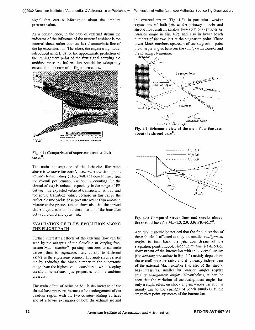
The comparison of the Mach number flowfield aroundthe whole plug nozzle, including the plug base, withthat obtained in case of still air at the same PRemphasizes the slipstream effect. It can be helpful tolook at the ambient pressure isobars displayed over theflowfield by a thick dashed line in Fig. 4.1. The still airsolution shows that the base pressure is nearly equal tothe ambient pressure. In particular, the ambientpressure isobar impinges on the plug wall and,downstream, the remaining part of the plug acts as acompressing surface. It can be seen that downstream ofthe ambient pressure isobar the flowfield shows nearlyconstant pressure, that acts also on the base flowregion. Only at the wake neck the flow must compressand the pressure becomes higher than ambient. On thecontrary, in the M«o=2 case, the driving mechanism ofthe expansion is the shroud base pressure value, that islower than the ambient pressure. Therefore, theexpansion covering the plug wall continuesdownstream the ambient pressure isobar, so that a partof the plug and the base are affected by pressure lowerthan ambient.
Therefore, as also stated above, the ML=2 solutionrepresents a typical case of closed wake behavior, witha base pressure value independent of p^ for increasingPR, whereas open wake with pb ~ p^ is shown in caseof still air. This different behavior at the same PRindicates that a different mechanism drives thetransition from open to closed wake.
In the still air case, it has been shown in the foregoingsection18 that transition takes place when the lastcharacteristic wave emanating from the primary nozzlelip impinges on the nozzle axis ahead of the stagnationpoint region. Conversely, in the in-flight case the samerole is played by the internal shock, that represents theboundary of the expansion process emanating from theshroud base and thus is the first and closer to the plug
10American Institute of Aeronautics and Astronautics
RTO-TR-AVT-007-V1 11
(c)2002 American Institute of Aeronautics & Astronautics or Published with Permission of Author(s) and/or Author(s)' Sponsoring Organization.
signal that carries information about the ambientpressure value.
As a consequence, in the case of external stream theindicator of the influence of the external ambient is theinternal shock rather than the last characteristic line ofthe lip expansion fan. Therefore, the engineering modelintroduced in Ref. 18 for the approximate prediction ofthe impingement point of the first signal carrying theambient pressure information should be adequatelyextended to the case of in-flight operations.
the external stream (Fig. 4.2). In particular, weakerexpansions of both jets at the primary nozzle andshroud lips result in smaller flow rotations (smaller liprotation angle in Fig. 4.2), and also in lower Machnumbers of the two jets at the stagnation point. Theselower Mach numbers upstream of the stagnation pointyield larger angles between the realignment shocks andthe dividing streamline.
Shroud Lip
•cV
Realignment AngleNozzle Lip Rotation Angle
Fig. 4.2: Schematic view of the main flow featuresabout the shroud base40.
Ambient Pressure isobar
Fig. 4.1: Comparison of supersonic and still aircases40.
The main consequence of the behavior illustratedabove is to move the open/closed wake transition pointtowards lower values of PR, with the consequence thatthe overall performance (without accounting for theshroud effect) is reduced especially in the range of PRbetween the expected value of transition in still air andthe actual transition value, because in this range theearlier closure yields base pressure lower than ambient.Moreover the present results show also that the shroudshape plays a role in the determination of the transitionbetween closed and open wake.
EVALUATION OF FLOW EVOLUTION ALONGTHE FLIGHT PATH
Further interesting effects of the external flow can beseen by the analysis of the flowfield at varying free-stream Mach number40, passing from zero to subsonicvalues, then to supersonic, and finally to differentvalues in the supersonic regime. The analysis is carriedout by reducing the Mach number in the supersonicrange from the highest value considered, while keepingconstant the exhaust gas properties and the ambientpressure.
The main effect of reducing ML is the increase of theshroud base pressure, because of the enlargement of thedead-air region with the two counter-rotating vorticesand of a lower expansion of both the exhaust jet and
Fig. 4.3: Computed streamlines and shocks aboutthe shroud base for ML=1 J, 2.0, 3.0; PR=61.740.
Actually, it should be noticed that the final direction ofthese shocks is affected also by the smaller realignmentangles to turn back the jets downstream of thestagnation point. Indeed, since the average jet directiondownstream of the interaction with the external stream(the dividing streamline in Rig. 4.2) mainly depends onthe overall pressure ratio, and it is nearly independentof the external Mach number (i.e. also of the shroudbase pressure), smaller lip rotation angles requiresmaller realignment angles. Nevertheless, it can beseen that the variation of the realignment angles hasonly a slight effect on shock angles, whose variation ismainly due to the changes of Mach numbers at thestagnation point, upstream of the interaction.
11American Institute of Aeronautics and Astronautics
12 RTO-TR-AVT-007-V1
(c)2002 American Institute of Aeronautics & Astronautics or Published with Permission of Author(s) and/or Author(s)' Sponsoring Organization.
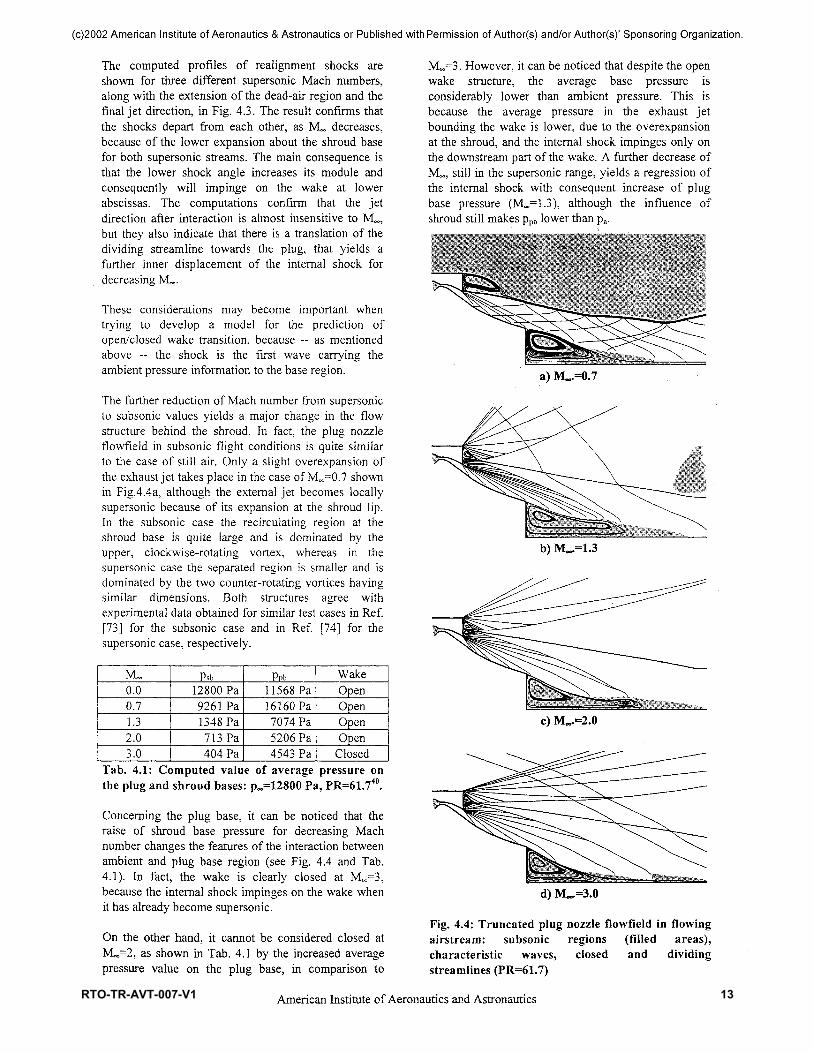
The computed profiles of realignment shocks areshown for three different supersonic Mach numbers,along with the extension of the dead-air region and thefinal jet direction, in Fig. 4.3. The result confirms thatthe shocks depart from each other, as M^ decreases,because of the lower expansion about the shroud basefor both supersonic streams. The main consequence isthat the lower shock angle increases its module andconsequently will impinge on the wake at lowerabscissas. The computations confirm that the jetdirection after interaction is almost insensitive to ML,but they also indicate that there is a translation of thedividing streamline towards the plug, that yields afurther inner displacement of the internal shock fordecreasing M«,.
These considerations may become important whentrying to develop a model for the prediction ofopen/closed wake transition, because -- as mentionedabove — the shock is the first wave carrying theambient pressure information to the base region.
The further reduction of Mach number from supersonicto subsonic values yields a major change in the flowstructure behind the shroud. In fact, the plug nozzleflowfield in subsonic flight conditions is quite similarto the case of still air. Only a slight overexpansion ofthe exhaust jet takes place in the case of Moo=0.7 shownin Fig.4.4a, although the external jet becomes locallysupersonic because of its expansion at the shroud lip.In the subsonic case the recirculating region at theshroud base is quite large and is dominated by theupper, clockwise-rotating vortex, whereas in thesupersonic case the separated region is smaller and isdominated by the two counter-rotating vortices havingsimilar dimensions. Both structures agree withexperimental data obtained for similar test cases in Ref.[73] for the subsonic case and in Ref. [74] for thesupersonic case, respectively.
ML0.00.71.32.03.0
Psb12800 Pa9261 Pa1348 Pa713 Pa404 Pa
PPb11568 Pa16160 Pa7074 Pa5206 Pa4543 Pa
WakeOpenOpenOpenOpen
ClosedTab. 4.1: Computed value of average pressure onthe plug and shroud bases: p^HSOO Pa, PR=61.740.
Concerning the plug base, it can be noticed that theraise of shroud base pressure for decreasing Machnumber changes the features of the interaction betweenambient and plug base region (see Fig. 4.4 and Tab.4.1). In fact, the wake is clearly closed at ML=3,because the internal shock impinges on the wake whenit has already become supersonic.
On the other hand, it cannot be considered closed atML=2, as shown in Tab. 4.1 by the increased averagepressure value on the plug base, in comparison to
Mc.0^3. However, it can be noticed that despite the openwake structure, the average base pressure isconsiderably lower than ambient pressure. This isbecause the average pressure in the exhaust jetbounding the wake is lower, due to the overexpansionat the shroud, and the internal shock impinges only onthe downstream part of the wake. A further decrease ofML, still in the supersonic range, yields a regression ofthe internal shock with consequent increase of plugbase pressure (ML=1.3), although the influence ofshroud still makes ppb lower than pa.
a) ML.=0.7
b) ML.=1.3
Fig. 4.4: Truncated plug nozzle flowfield in flowingairstream: subsonic regions (filled areas),characteristic waves, closed and dividingstreamlines (PR=61.7)
12American Institute of Aeronautics and Astronautics
RTO-TR-AVT-007-V1 13

(c)2002 American Institute of Aeronautics & Astronautics or Published with Permission of Author(s) and/or Author(s)' Sponsoring Organization.
A different behavior is shown in the subsonic case,where the average base pressure on the shroud is closerto the ambient pressure value. The consequence is thatthe exhaust jet does not overexpand significantly, likein the case of still air, and thus there is a directinfluence of ambient pressure on the wake.
5. PLUG NOZZLE BASE PRESSUREVERSUS FLIGHT ALTITUDE
prepared byPhilippe ReijasseON ERA, Meudon, France
In reference to the full-length aerospike nozzle, thedetermination of thrust budget of a truncated plugnozzle necessitates to solve the additional question ofthe plug base pressure. It has to be emphasized4 that forplug length such that the base height is small comparedto the total plug height, the contribution of basepressure is negligible with respect to the overall thrustof the nozzle. Furthermore Navier-Stokescomputations29 have shown that even for a 20%truncated plug nozzle, base drag should represent only5% of the total thrust (inner nozzle, plug and base) athigh nozzle pressure ratio (PR).
PLUG NOZZLE BASE-FLOW REGIMES
At low altitude -or low PRs-, ambient pressure is highand greater than the nozzle static pressure at the (cowl)lip. The outer free jet boundary is close enough to thenozzle, and compression waves strike on the nozzlecontour and the inner shear layer, see Fig.5.1a19. Thecompression waves impinging on the nozzle contourincrease the nozzle wall pressure. The compressionwaves impinging on the inner shear layer surroundingthe subsonic region increase the nozzle base pressure.
As altitude increases, or ambient pressure decreases,compression waves move down the nozzle contour.When ambient pressure becomes lower than the nozzlelip pressure, expansion waves form and are followedby an internal shock which no longer strike the plugcontour. In that case, see Fig. 5.1b, the pressure profilealong the nozzle contour remains constant with furtherdecreases in ambient pressure. The nozzle basepressure, however, remains under the influence ofambient pressure as long as the internal shock impingeson the inner shear layer surrounding the subsonicregion.
At high PRs, when the internal shock movesdownstream of the sonic line in the wake of the baseflow, see Fig. 5.1c, the decrease of ambient pressuredoes not affect the nozzle base pressure. Once the basepressure becomes insensitive to the ambient pressure,the aerospike flow regime is called * closed wake'regime. Prior to this point, while the nozzle base
pressure is sensitive to the ambient pressure, theaerospike is in the 'open wake' regime.
We have to take care with this wake regimedesignation, closed or open, because it concerns onlythe sensitivity of base pressure versus the ambientpressure for truncated plug nozzle application. Thus thedesignation of these regimes is totally de-correlatedwith the recirculation flow pattern. This sensitivity toambient pressure has been well experimentallyidentified for different types of plug nozzleconfigurations19'20'27, annular or linear, clustered or not.Hagemann8 had proposed a way to determine thetransition point from an open wake to a closed wakethanks to the Method of Characteristics. This transitionshould occur when the right-running characteristicissued from the nozzle lip intersects the separated shearlayer at the foot of the trailing shock. This methodwhen applied to a linear aerospike21 shows a relativelygood agreement and slightly underestimates thetransition point, see Fig.5.2.
Fig. 5.1 - Plug nozzle flowfields : a) at low PR, b) atintermediate PR, c) at high PR19.Indeed, in the case of plug nozzle configurationanalysed in Ref. 19, a closed recirculation bubbleoccurs at all PRs. It means that a vortical region isbounded by the nozzle base surface and the inner shearlayer which reattaches itself downstream of the base.The reattachment region starts the development of asupersonic thick wake on the centerline. So, the so-called open wake regime of truncated plug nozzles - in
13American Institute of Aeronautics and Astronautics
14 RTO-TR-AVT-007-V1

(c)2002 American Institute of Aeronautics & Astronautics or Published with Permission of Author(s) and/or Author(s)' Sponsoring Organization.
terms of base pressure insensitivity to ambient pressure- can even occur when a closed recirculation bubbleforms downstream of the base.
0.2
0.1
0.0
Cold Flow Test (20%)Empirical Equation . : :
10 20 100 20050Pc/Pa
Fig. 5.2: Normalised base pressure versus PR.Experimental data from a linear aerospike nozzlecold gas model21 compared with Hagemann'sassumption8.
Fig. 5.3: Subsonic open wake flow patterndownstream of a truncated plug nozzle base.
Furthermore, it is also possible that the separated innershear layer does not reattach itself downstream of thebase surface. This could be the case of a truncated plugnozzle with a large base surface comparatively to theannular section of the incoming supersonic jet, see Fig.5.3. In such a base flow pattern, there is a subsonicopen wake -really opened this time in terms of fluidmechanics-, and the base pressure is close to theambient pressure. Thus, in that case, the problem is notto determine the base pressure, but to predict at whichvalue of pc/pa the transition 'opening-closing' of therecirculation bubble occurs.
If the base flow pattern is a closed recirculation bubble,whatever the plug nozzle wake regime -closed or open-, then the determination of the base pressure insupersonic regime is submitted to the same flowphysics, namely the physics of the 'SupersonicTurbulent Flow Reattachment'. Motivated by the basedrag prediction not only for truncated plug nozzles butmainly for projectile and missile applications, thesupersonic base flow physics have been extensivelyinvestigated in the world since the 50's. Thanks tomany investigations performed downstream of the baseof two-dimensional backward-facing steps, it has beenderived analytical, pure-empirical and theoretico-empirical models as those presented below.
BASE PRESSURE PREDICTION
Pure empirical relationshipsFick et al.20 have evaluated empirical relations of thebase pressure versus constant incoming Mach numberMe and specific heat ratio. A comparison with the fewavailable measurements showed that the two empiricalrelations issued from Ref. 30, see Eqs (5.1) and (5.2)below, failed to produce reliable results.
_Pb ~
Q.846/?e(5.1)
- 0.92Me2 - 0.03
(5.2)
A slighly better agreement was found20 notably for 12-16% plug lengths if it was assumed that the basepressure results from a very simple averaging betweenpressure pe at the truncated nozzle exit and pressure pdat the exit of the hypothetical design full-length plug,as written below :
pb=k(pe+pd); = 0.5. (5.3)
When applied to linear aerospike nozzles, it wasfound21 that the constant k had to be changed from 0.5to 0.3 according to measured data.
Derived from cylinders and cones, an originalempirical base-pressure model31 has been changed inRef. 20 by setting an exponent which should take intoaccount the negative angle of the flow incoming thebase region. For cold flow tests, and setting theexponent at 0.35, agreement with measured basepressure has been attainable with the "conical-approximation" equation below,
\0.35
0.025+ -0.906
(5.4)
v 2 e
The empirical model derived in Re. 20 from a cylinderembedded in supersonic flow also gives a goodagreement if Mach number Me and a sonic pressureratio are introduced, thus we obtain the "cylindrical-approximation" equation below,
Pi, =PeMe fJ_Fu+u 0.05+ -0.967
(5-5)
Onofri et al.32 have also evaluated Eqs. (5.4) and (5.5),and another plug nozzle base model proposed by
14American Institute of Aeronautics and Astronautics
RTO-TR-AVT-007-V1 15
(c)2002 American Institute of Aeronautics & Astronautics or Published with Permission of Author(s) and/or Author(s)' Sponsoring Organization.
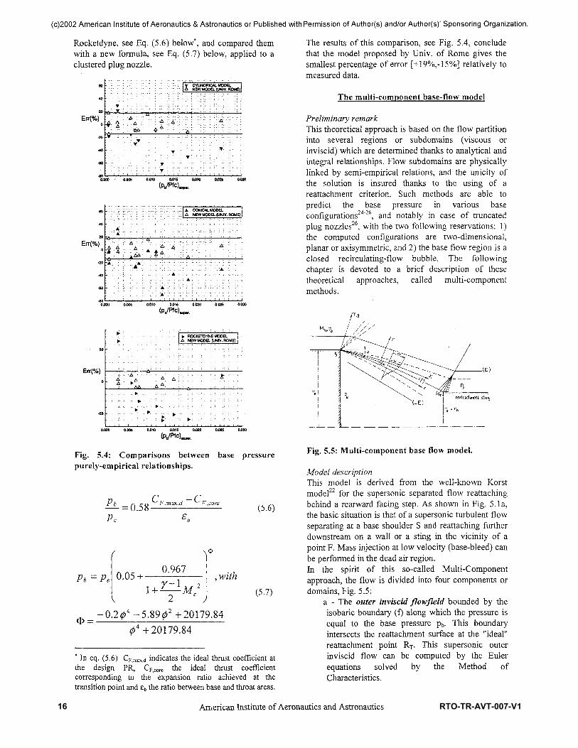
Rocketdyne, see Eq. (5.6) below*, and compared themwith a new formula, see Eq. (5.7) below, applied to aclustered plug nozzle.
Err(%)
0.000 : 0.005 0.010 0.015 04)20 04)25
Err(%)
:.::: I A CONICAL MODEL;:;:| A NEW MODEL (UNtV. ROME)!
0.000 0.005 0.010 0.015 0.025 0.030
Err(%)
»• ROCKETDYNE MODELI A NEW MODEL (UNIV. ROME)
A A ;
lAA___^
0.000 0.005 04)10 04)15 04)20 04)25 0.030
Fig. 5.4: Comparisons betweenpurely-empirical relationships.
base pressure
.Cfll-C"
PC
(5.6)
Pb = 0.05 + - 0.967
1 + - (5.7)
20179.8420179.84
* In eq. (5.6) CF)maXid indicates the ideal thrust coefficient atthe design PR, CF)Core the ideal thrust coefficientcorresponding to the expansion ratio achieved at thetransition point and £b the ratio between base and throat areas.
15
The results of this comparison, see Fig. 5.4, concludethat the model proposed by Univ. of Rome gives thesmallest percentage of error [+19%,-15%] relatively tomeasured data.
The multi-component base-flow model
Preliminary remarkThis theoretical approach is based on the flow partitioninto several regions or subdomains (viscous orinviscid) which are determined thanks to analytical andintegral relationships. Flow subdomains are physicallylinked by semi-empirical relations, and the unicity ofthe solution is insured thanks to the using of areattachment criterion. Such methods are able topredict the base pressure in various baseconfigurations24"26, and notably in case of truncatedplug nozzles26, with the two following reservations: 1)the computed configurations are two-dimensional,planar or axisymmetric, and 2) the base flow region is aclosed recirculating-flow bubble. The followingchapter is devoted to a brief description of thesetheoretical approaches, called multi-componentmethods.
Fig. 5.5: Multi-component base flow model.
Model descriptionThis model is derived from the well-known Korstmodel22 for the supersonic separated flow reattachingbehind a rearward facing step. As shown in Fig. 5. la,the basic situation is that of a supersonic turbulent flowseparating at a base shoulder S and reattaching furtherdownstream on a wall or a sting in the vicinity of apoint F. Mass injection at low velocity (base-bleed) canbe performed in the dead air region.In the spirit of this so-called Multi-Componentapproach, the flow is divided into four components ordomains, Fig. 5.5:
a - The outer inviscid flowfield bounded by theisobaric boundary (f) along which the pressure isequal to the base pressure pb. This boundaryintersects the reattachment surface at the "ideal"reattachment point RT. This supersonic outerinviscid flow can be computed by the Eulerequations solved by the Method ofCharacteristics.
American Institute of Aeronautics and Astronautics
16 RTO-TR-AVT-007-V1
(c)2002 American Institute of Aeronautics & Astronautics or Published with Permission of Author(s) and/or Author(s)1 Sponsoring Organization.
b - The rapid expansion of the boundary-layerwhen it separates at base shoulder S. This flowexpansion can be treated by a Prandtl-Meyerexpansion if we assume the viscous termsinfluence are negligible in such a process,
c - The turbulent mixing-layer developing fromthe separation point S along the isobaric boundary(f). Transfers of momentum, mass and energybetween the outer high velocity stream and theclosed recirculation bubble take place in thismixing layer. The velocity distribution across theturbulent mixing-layer is represented by theclassical relationship:
— = -(1 +erf (#)), (5.8)ue 2
where % is a similarity variable. The distributionsof stagnation enthalpy and species concentrationare deduced from the velocity distribution byassuming Prandtl number and Schmidt numberequal to unity.d - The reattachment region where the mixinglayer impinges on the reattachment surface, theouter flow being simultaneously deflected in sucha way so that it becomes parallel to the surface.This deflection entails the formation ofcompression waves which focalize into thereattachment shock. A compatibility condition atthe reattachment point have to be expressed via anempirical criterion. Onera has developed theconcept of Angular Reattachment Criterionintroduced by Carriere and Sirieix23. This angularcriterion states that the isobaric outer flowdeflection, xj/, at reattachment point must satisfy alaw given by semi-empirical relationships23"25.
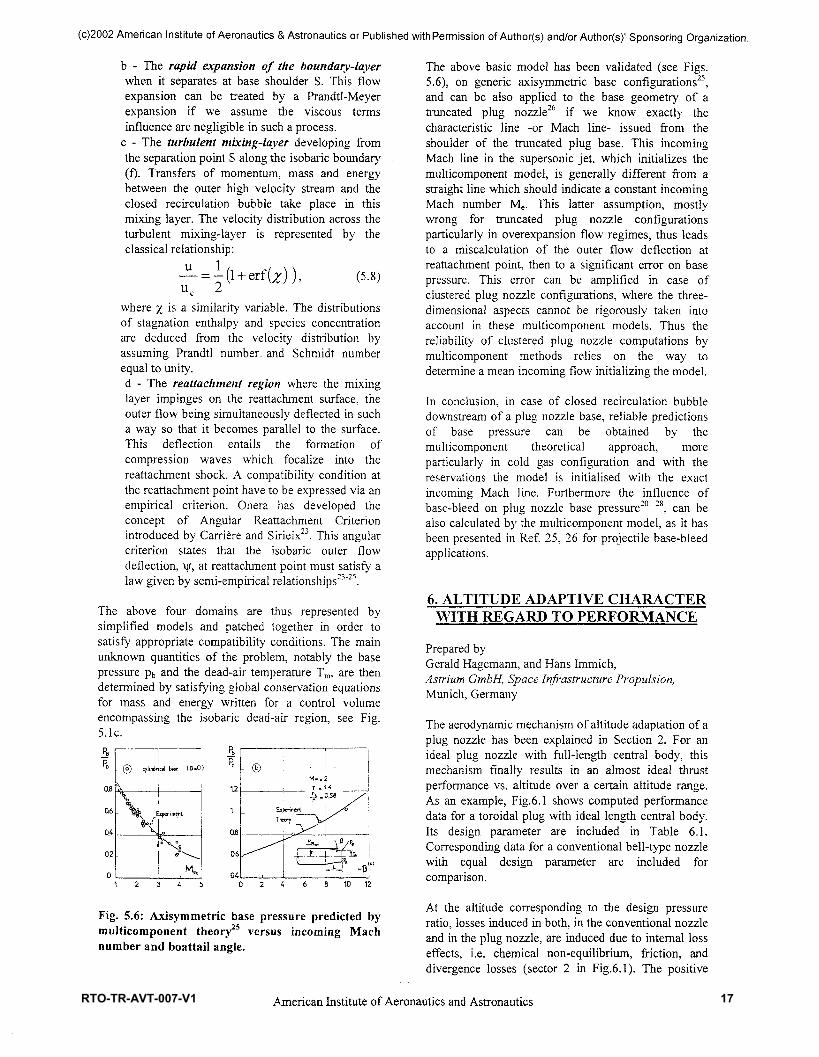
The above four domains are thus represented bysimplified models and patched together in order tosatisfy appropriate compatibility conditions. The mainunknown quantities of the problem, notably the basepressure pb and the dead-air temperature Tm, are thendetermined by satisfying global conservation equationsfor mass and energy written for a control volumeencompassing the isobaric dead-air region, see Fig.5.1c.
HePC
oa
0.6
04
0.2
0
0 cylindr
\
- S$=N E
iv.
cal b*« (3.0
jpenmenl
V.Meo 0.4
10 12
Fig. 5.6: Axisymmetric base pressure predicted bymulticomponent theory25 versus incoming Machnumber and boattail angle.
The above basic model has been validated (see Figs.5.6), on generic axisymmetric base configurations25,and can be also applied to the base geometry of atruncated plug nozzle26 if we know exactly thecharacteristic line -or Mach line- issued from theshoulder of the truncated plug base. This incomingMach line in the supersonic jet, which initializes themulticomponent model, is generally different from astraight line which should indicate a constant incomingMach number Me. This latter assumption, mostlywrong for truncated plug nozzle configurationsparticularly in overexpansion flow regimes, thus leadsto a miscalculation of the outer flow deflection atreattachment point, then to a significant error on basepressure. This error can be amplified in case ofclustered plug nozzle configurations, where the three-dimensional aspects cannot be rigorously taken intoaccount in these multicomponent models. Thus thereliability of clustered plug nozzle computations bymulticomponent methods relies on the way todetermine a mean incoming flow initializing the model.
In conclusion, in case of closed recirculation bubbledownstream of a plug nozzle base, reliable predictionsof base pressure can be obtained by themulticomponent theoretical approach, moreparticularly in cold gas configuration and with thereservations the model is initialised with the exactincoming Mach line. Furthermore the influence ofbase-bleed on plug nozzle base pressure20' 28, can bealso calculated by the multicomponent model, as it hasbeen presented in Ref. 25, 26 for projectile base-bleedapplications.
6. ALTITUDE ADAPTIVE CHARACTERWITH REGARD TO PERFORMANCE
Prepared byGerald Hagemann, and Hans Immich,Astrium GmbH, Space Infrastructure Propulsion,Munich, Germany
The aerodynamic mechanism of altitude adaptation of aplug nozzle has been explained in Section 2. For anideal plug nozzle with full-length central body, thismechanism finally results in an almost ideal thrustperformance vs. altitude over a certain altitude range.As an example, Fig.6.1 shows computed performancedata for a toroidal plug with ideal length central body.Its design parameter are included in Table 6.1.Corresponding data for a conventional bell-type nozzlewith equal design parameter are included forcomparison.
At the altitude corresponding to the design pressureratio, losses induced in both, in the conventional nozzleand in the plug nozzle, are induced due to internal losseffects, i.e. chemical non-equilibrium, friction, anddivergence losses (sector 2 in Fig.6.1). The positive
16American Institute of Aeronautics and Astronautics
RTO-TR-AVT-007-V1 17

(c)2002 American Institute of Aeronautics & Astronautics or Published with Permission of Author(s) and/or Author(s)' Sponsoring Organization.
effect of altitude adaptation is indisputable; forpressure ratios below the design pressure ratio, the plugnozzle performance is practically equal to thetheoretical ideal expansion. For pressure ratios higherthan the design pressure ratio, the plug nozzle behavesas a conventional nozzle, the loss in altitude adaptationincluded (sector 3).
The truncation of the central plug body, which is ofadvantage due to the huge full-length and highstructural masses of the contoured central body, resultsin a different flow and performance behaviourcompared to the full-length plug nozzle. This has beendiscussed in detail in Section 2.
Chamber pressure pc= 100 barPropel lantsMixture ratioGeometrical area ratio
hydrogen / oxygeno/f=6e-55
Table 6.1: Design parameter of toroidal plug nozzleand reference bell nozzle used for computations.
At lower pressure ratios an open wake flow establishes,with a pressure level practically equal to the ambientpressure. At a certain pressure ratio close to the designpressure ratio of the full-length plug nozzle, the baseflow suddenly changes its character and turns over tothe closed form, characterised by a constant basepressure. At the transition point the pressure within thewake approaches a value which is below ambientpressure, and the full base area induces a negativethrust. This thrust loss depends on the percentage oftruncation and the total size of the base area. Publishedexperimental data and numerical simulations revealedan increasing thrust loss for shorter plug bodies, sincethe total base area increases.
Base pressures during open wake condition may beinfluenced by base bleed injection. Former experimentshave shown that a small amount of bleed gas, i.e. -1%of total mass flow rate, expanded into the base areaslightly increases the base pressures during open wakeconditions, and thus has a positive influence on theplug performance efficiency, see e.g. Ref. 45.
Performance data of a numerically simulated truncatedplug nozzle are included in Fig. 6.2 and compared tothe same plug nozzle with full-length central body anda conventional bell nozzle as shown in Fig. 6.1. Designparameter of this truncated plug nozzle are the same asfor the full-length plug, see Table 6.1. The thrust loss ata certain altitude where transition in wake behaviouroccurs, becomes obvious. Its value of course dependson the real base pressure loss, in the numericalsimulations based on quasi-steady state simulations, apressure loss of approx. 15% was predicted.
4900
4700
1£. 4500
CDtoB 4300Q.
"o 4100
1g. 3900
3700
3500
J — - — adapted, ideal nozzle, 1 D-analysis——— plug nozzle, ideally contoured plug body, £EKWm=55- — - bel! nozzle, e=55
15000 30000 45000flight altitude / [m]
60000
Fig. 6.1: Performance characteristic of anideal plug nozzle and a bell-type nozzle. Idealexpansion into ambience included for comparison.
The principle of performance characteristic calculatedwith these numerical analyses are confirmed / provenby experiments, see e.g Wasko'45
The performance of plug nozzles is adversely affectedby the external air stream flow, i.e. the aspiration effectof the external flow reduces slightly performance andalso favours an earlier change in wake flowdevelopment for truncated plug nozzles, see Ref. 42-45. Cold-flow tests showed that the effect of externalflow on performance is confined to only a narrowrange of external flow speeds with Mach numbersnearly unity.
Altitude compensation capability of plug nozzles forhigher ambient pressures is indisputable. Since plugnozzles lose this capability for higher pressure ratiosthan the design pressure ratio, the latter should bechosen as high as possible. Taking this into account,plug nozzles will feature an even better overallperformance than shown in Fig.6.1 and 6.2.
4900
4700
I— 4500
0)CO3 4300Q.E"o 4100
*5g- 3900
3700
3500
— - — adapted, ideal nozzle, 1 D-analysis............. p|Ug nozzle, ideally contoured plug body, egaom=55——— plug nozzle, truncated plug body, eeeom=55— - - bel! nozzle, e=55
15000 30000 45000flight altitude / [m]
60000
Fig. 6.2 : Performance characteristic of anideal plug nozzle, a truncated plug nozzle, and abell-type nozzle. Ideal expansion into ambienceincluded for comparison.
17American Institute of Aeronautics and Astronautics
18 RTO-TR-AVT-007-V1

throai^ design characteristic
Mn
Fig. 7.1: Plug nozzle contour definitionfully based on Prandtl-Meyer expansion fanaround corner.
c
(c)2002 American Institute of Aeronautics & Astronautics or Published with Permission of Author(s) and/or Author(s)1 Sponsoring Organization.- Prandtl-Meyer expansion around corner
Only for equal geometrical area ratios of plug nozzlesand conventional bell nozzles, plug nozzles have worsehigh altitude performance due to truncation.
A plug nozzle is an integral part of the launcher.Ambient flow therefore may slightly influence theperformance characteristic as long as the base flow isin open wake condition, see Section 5 for a detaileddiscussion. In contrast, a conventional engine with bell-type nozzle extension needs a thrust frame for engineintegration. As this kind of engine layout cannot fill outthe launcher base area, additional base drag isgenerated in case of ambient flow. This drag for aconventional bell-type engine nozzle should be takeninto account for a fair performance trade-off betweenplug- and a conventional nozzle. The same holdsactually also for the engine mass estimation.
7. CONTOUR DESIGN METHODS
Prepared byGerald Hagemann, and Hans Immich,Astrium GmbH, Space Infrastructure Propulsion,Munich, Germany
An ideally contoured supersonic flow nozzle producesan uniform, one-dimensional flow profile in the exitplane. The design philosophy is that at the designpressure ratio all expansion waves propagating throughthe flow towards the nozzle wall and therebyaccelerating the flow to the desired design Machnumber are cancelled out by a proper wall contourdesign.The most simple design approach for the contour of aplug nozzle is based on a Prandtl-Meyer expansionaround a corner for the throat inclination and also forthe further contour definition. Figure 7.1 illustrates theprinciple of this approach, which was independentlyproposed by Angelina6'34 and Lee35 A mass flowbalance along each straight characteristic of thePrandtl-Meyer expansion fan finally defines thecontour. Since this approach is purely based on thePrandtl-Meyer equations, it is however only fully validfor planar plug nozzle configurations with uniform,one-dimensional inflow.
To take into account the curved propagation ofexpansion waves for axis-symmetrical flow conditions,the method of characteristics has to be applied for thecontour definition of a toroidal plug nozzle. Thisapproach has also been proposed by Angelina in 1963,Ref.34. Further advantage of applying the method ofcharacteristics is, that non-uniform inflow conditionsthrough the throat or a primary internal expansionnozzle are taken into account. A detailed discussion onthis is included in Ref. 77.
For high Mach number plug nozzles with sonic outflowthough the throat and fully external expansion, largeturning angles of the flow and thus of the throat are
18
Fig. 7.2:Toroidal GSTP plug design with acombined internal and external expansion. Internalexpansion in non-symmetric nozzle to Machnumber, overall plug design Mach number MD(cold air experiment).
required. As an example, the FESTIP linear plug model#1 tested within the frame of the ESA FESTIPprogramme by DaimlerChrysler Aerospace wasdesigned for an exit flow with a Mach number of MD =4.23. For the purely external expansion with air, thisrequires a flow turning angle of approx. 0 =71°, seee.g. References 8, 36, and 77 for further details.A primary internal expansion may be realised to avoidthe large turning angle, as it has been realised e.g. withthe FESTIP plug model #2, the LION plug nozzle, andthe GSTP toroidal plug nozzle, Ref.77.For the GSTP plug tested within the frame of the ESAGSTP Programme by Volvo Aero Corporation at FFAin Sweden, a non-symmetric internal expansion nozzleproducing a uniform, one-dimensional flow profile inthe exit plane of the internal expansion nozzle wasrealised.9
Figure 7.2 gives details of the chosen design approach.The exhaust flow initially expands in the non-symmetric internal nozzle along the circular arc BDwith the radius BS or SD to a Mach number of Mid .Along the internal exit characteristic DE, the flow isuniform. In the region DEF, this uniform flow ispreserved, until then the external expansion takes placeto the chosen exit Mach number of MD. The contourDFG is defined based on the method of characteristics.Further details on the design are included in Ref. 77.
For truncated plug nozzles, an additional designapproach was developed by Rao31 taking into accountthat a simple truncation of a plug nozzle with a fulllength central body for maximum performance doesnot automatically result in the best performingtruncated plug nozzle. Therefore, Rao proposed adesign method for truncated plug nozzles, based on a
American Institute of Aeronautics and Astronautics
RTO-TR-AVT-007-V1 19
(c)2002 American Institute of Aeronautics & Astronautics or Published with Permission of Author(s) and/or Author(s)1 Sponsoring Organization.
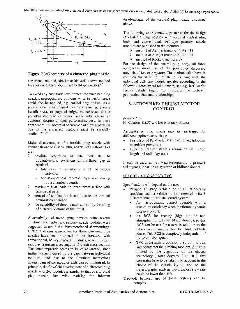
Figure 7.3:Geometry of a clustered plug nozzle.variational method, similar to his well known methodfor shortened, thrust-optimised bell-type nozzles.37
To avoid any base flow development for truncated plugnozzles, non-optimised contours w.r.t. to performancecould also be applied, e.g. conical plug bodies. As aplug engine is an integral part of a launcher, even abenefit w.r.t. to payload might be achieved due apotential decrease of engine mass with alternativecontours, despite of their performance loss. In theseapproaches, the potential occurrence of flow separationdue to the imperfect contours must be carefullystudied.29'41'54
Major disadvantages of a toroidal plug nozzle withannular throat or a linear plug nozzle with a throat slotare:> possible generation of side loads due to
circumferential deviations of the throat gap asresult of- tolerances in manufacturing of the nozzle
hardware,- non-symmetrical thermal expansion during
thrust chamber operation,> maximum heat loads on large throat surface with
tiny throat gaps> control of combustion instabilities in the toroidal
combustion chamber.> No capability of thrust vector control by throttling
of different sections of the throat.
Alternatively, clustered plug nozzles with severalcombustion chamber and primary nozzle modules weresuggested to avoid the abovementioned shortcomings.Different design approaches for these clustered plugnozzles have been proposed in the literature, withconventional, bell-type nozzle modules, or with nozzlemodules featuring a rectangular, 2-d exit cross section.The latter approach seems to be of advantage, sincefurther losses induced by the gaps between individualmodules, and due to the flowfield interactionsdownstream of the modules exits can be minimised. Inprinciple, the flowfield development of a clustered plugnozzle with 2-d modules is similar to that of a toroidalplug nozzle, but with avoiding the inherent
disadvantages of the toroidal plug nozzle discussedabove.
The following approximate approaches for the designof clustered plug nozzles with toroidal central plugbody and conventional, bell-type primary nozzlemodules are published in the literature:
> method of Aerojet (method 1), Ref. 38> method of Aerojet (method 2), Ref. 38> method of Rocketdyne, Ref. 3 9
For the design of the central plug body, all threeapproaches make use of the previously discussedmethods of Lee or Angelina. The methods also have incommon the definition of the outer ring with theindividual bell-type module nozzles according to thefollowing geometrical relationship, see e.g. Ref. 38 forfurther details. Figure 7.3 illustrates the differentgeometrical data and relationships.
8. AEROSPIKE: THRUST VECTORCONTROL
prepared byM. Calabro, EADS-LV, Les Mureaux, France
Aerospike or plug nozzle may be envisaged fordifferent applications such as:• First stage of RLV or ELV (use of self-adaptability
to ambient pressure ),• Upper or transfer stages ( reason of use : short
length and radial lay-out)
It may be used, as well with turbopumps or pressurefed engines, it can be axisymetric or bidimensionnal.
SPECIFICATIONS FOR TVC
Specifications will depend on the use:• Winged 1st stage vehicle or SSTO Generally
speaking such a vehicle is implemented with 3different kind of attitude control system :• An aerodynamic control operable with a
maximum efficiency when maximum dynamicpressure occurs;
• An RCS for reentry (high altitude andatmospheric flight over Mach about 2), so thisACS can be use for ascent hi addition to theothers ones, mainly for the high altitudephase. This RCS is completely independent ofthe propulsion system;
• TVC of the main propulsion used only to trimand counteract the pitching moment, (} max islimited by the capability of the chosentechnology ( some degrees :3 to 10+), thisconstraint have to be taken into account in thechoice of the vehicle lay-out and on thetrajectography analysis nevertheless slew ratecould be lower than 5°/s.
Trade-off between use of these systems can becomplex.
19American Institute of Aeronautics and Astronautics
20 RTO-TR-AVT-007-V1
(c)2002 American Institute of Aeronautics & Astronautics or Published with Permission of Author(s) and/or Author(s)' Sponsoring Organization.
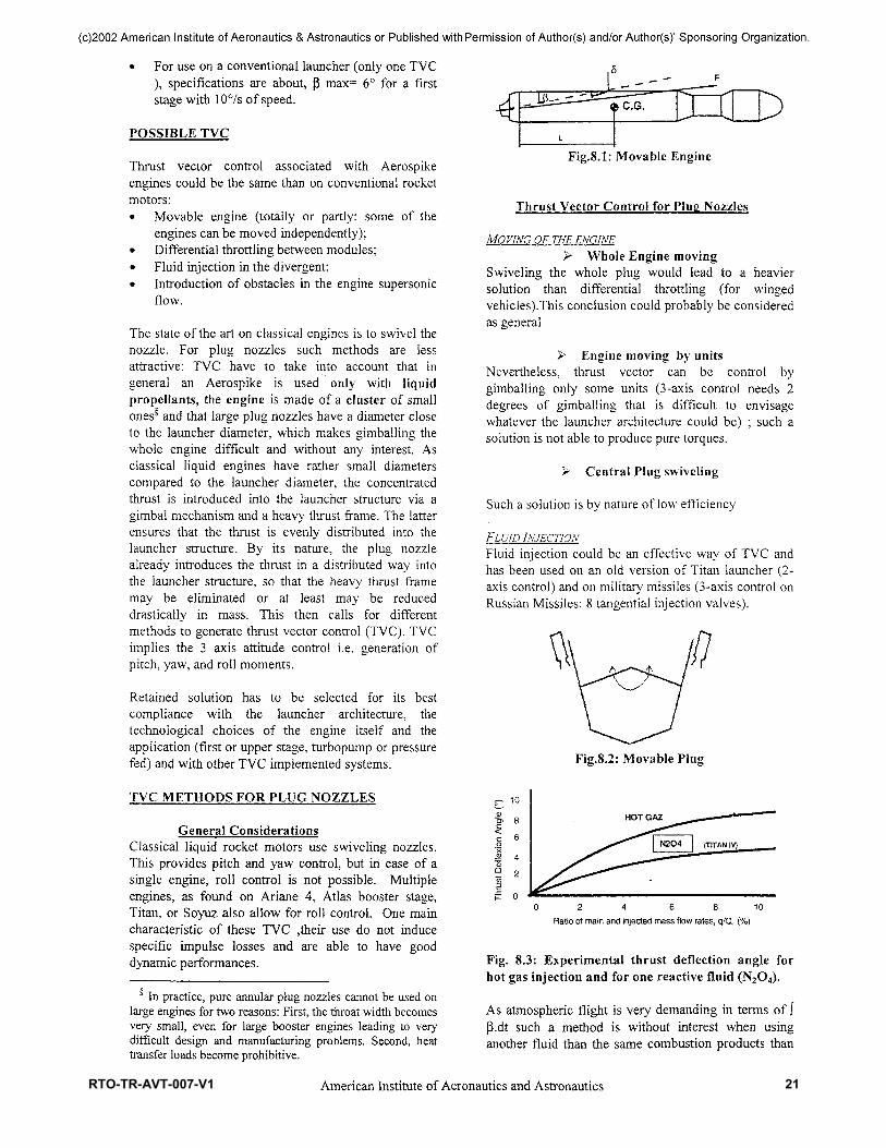
• For use on a conventional launcher (only one TVC), specifications are about, p max= 6° for a firststage with 10% of speed.
POSSIBLE TVC
Thrust vector control associated with Aerospikeengines could be the same than on conventional rocketmotors:• Movable engine (totally or partly: some of the
engines can be moved independently);• Differential throttling between modules;• Fluid injection in the divergent;• Introduction of obstacles in the engine supersonic
flow.
The state of the art on classical engines is to swivel thenozzle. For plug nozzles such methods are lessattractive: TVC have to take into account that ingeneral an Aerospike is used only with liquidpropellents, the engine is made of a cluster of smallones§ and that large plug nozzles have a diameter closeto the launcher diameter, which makes gimballing thewhole engine difficult and without any interest. Asclassical liquid engines have rather small diameterscompared to the launcher diameter, the concentratedthrust is introduced into the launcher structure via agimbal mechanism and a heavy thrust frame. The latterensures that the thrust is evenly distributed into thelauncher structure. By its nature, the plug nozzlealready introduces the thrust in a distributed way intothe launcher structure, so that the heavy thrust framemay be eliminated or at least may be reduceddrastically in mass. This then calls for differentmethods to generate thrust vector control (TVC). TVCimplies the 3 axis attitude control i.e. generation ofpitch, yaw, and roll moments.
Retained solution has to be selected for its bestcompliance with the launcher architecture, thetechnological choices of the engine itself and theapplication (first or upper stage, turbopump or pressurefed) and with other TVC implemented systems.
TVC METHODS FOR PLUG NOZZLES
General ConsiderationsClassical liquid rocket motors use swiveling nozzles.This provides pitch and yaw control, but in case of asingle engine, roll control is not possible. Multipleengines, as found on Ariane 4, Atlas booster stage,Titan, or Soyuz also allow for roll control. One maincharacteristic of these TVC ,their use do not inducespecific impulse losses and are able to have gooddynamic performances.
§ In practice, pure annular plug nozzles cannot be used onlarge engines for two reasons: First, the throat width becomesvery small, even for large booster engines leading to verydifficult design and manufacturing problems. Second, heattransfer loads become prohibitive.
Fig.8.1: Movable Engine
Thrust Vector Control for Plug Nozzles
MO VING OF THE ENGINE^ Whole Engine moving
Swiveling the whole plug would lead to a heaviersolution than differential throttling (for wingedvehicles).This conclusion could probably be consideredas general
> Engine moving by unitsNevertheless, thrust vector can be control bygimballing only some units (3-axis control needs 2degrees of gimballing that is difficult to envisagewhatever the launcher architecture could be) ; such asolution is not able to produce pure torques.
> Central Plug swiveling
Such a solution is by nature of low efficiency
FLUID INJECTIONFluid injection could be an effective way of TVC andhas been used on an old version of Titan launcher (2-axis control) and on military missiles (3-axis control onRussian Missiles: 8 tangential injection valves).
Fig.8.2: Movable Plug
10
8
6
0 2 4 6 8 1 0Ratio of main and injected mass flow rates, q/Q, (%)
Fig. 8.3: Experimental thrust deflection angle forhot gas injection and for one reactive fluid (N2O4).
As atmospheric flight is very demanding in terms of Jp.dt such a method is without interest when usinganother fluid than the same combustion products than
20American Institute of Aeronautics and Astronautics
RTO-TR-AVT-007-V1 21

(c)2002 American Institute of Aeronautics & Astronautics or Published with Permission of Author(s) and/or Author(s)' Sponsoring Organization.
these of engine chamber (direct injection from chamberor gas produced by small engines) but such a solution -technically feasible-has never be developed for anoperational use.
TVC BY DIFFERENTIAL THROTTLINGTVC may be achieved by reducing the chamberpressure in one nozzle and increasing the pressure inthe opposite one (from one axis standpoint). The thrustof one nozzle is about proportional to the nozzlestagnation pressure.• A first solution consist to have thrust variation of
nozzles independently of the others:- Or turbopump(s) have to be dimensioned for
maximum flow rate and pressure- Or separate booster pumps are implemented;This may not be cost or weight effective and alsoresponse times may become too long.
• Another option is to use throttling valves betweentwo chambers fed by a common turbopump (novariation of overall mass flow rate).
The resulting moments are estimated by thecontributions of the individual nozzles.To accomplish TVC by thrust modulation, i.e., byreducing/ increasing the pressure in a set of individualcombustion chambers, the cluster of individualcombustion chambers has to be divided into fourgroups. For each of these groups, a throttling valve isrequired in the propellant feed lines, and in casebooster pumps are used to increase the pressure, valvesconnecting the outlet(s) of the booster pump(s) to theinjectors are required.
A single annular plug nozzle only allows for pitch andyaw control when using differential throttling. Thelinear plug nozzle allows for all three types of control,provided the upper and lower part of the plug haveindividually throttleable combustion chambers.
Fig.8.4: Schematic of flaps: on the plug or on thebase area.
JVC Using FlapsVanes or obstacles are well-known means toaccomplish TVC on launchers. The oldest launcherexamples used vanes (German V-2 during World WarII. American Scout launcher, ...). A disadvantage isthat vanes are exposed all the time to the full impact ofthe hot combustion gases and can be erodedsubstantially during operation and reduce theperformance of the rocket motor (losses of specificimpulse). Flaps are exposed only when they are usedand represent a better solution than vanes or than fluidinjection, maintaining a (3 don't need any consumptionof fluid; so, they may have some advantages inconjunction with plug nozzles.
Need of an accurate Parametric Model
Mixture RatioThrust levelThrust VectoringAltitude
Engine Design
Engine Performances:Forces, MomentsSpecific impulse
Trajectory Optimization:Vehicle Performance
Launch vehicle performances are evaluated bycomputing the optimum vehicle trajectory underconstraints; one part of the essential data for anaccurate trajectory simulation is the engineperformance.
The Aerospike engine performance is significantlymore complex than a conventional engine since anAerospike is capable of thrust modulation (plusvariable mixture ratio and thrust level) and has a
coo
DLO
100% PL, MR * 7.0100% PL, MR = 5.5
60% PL, .MR = 7.060% PL, MR « 5.5
altitudeFig 8.7: X33 Computed pitching moment for15%thrust vector versus altitude for 2 power leveland 2 mixture ratio ,Isp versus altitude
21American Institute of Aeronautics and Astronautics
22 RTO-TR-AVT-007-V1

(c)2002 American Institute of Aeronautics & Astronautics or Published with Permission of Author(s) and/or Author(s)' Sponsoring Organization.
complex flow that interacts with the externalaerodynamic and susceptible to operate or in "closedwake" or in "open wake" and perhaps to go from one tothe other under external solicitations.
So, specific impulse delivered by the whole engine willdepends of mixture ratio, thrust level, rate of throttling,vehicle attitude and altitude. Forces and moments(normal force, pitching moment) have a very nonlinearevolution at lower altitude and significantly differentthan in vacuum.
practicable for larger annular plug nozzles; Movablesunits seems possible for small upper stages
ON-BOARDMODEL
GROUND TESTSVALIDATIONS FLIGHT
SIMULATIONS
PARAMETRICMODEL
From control standpoint, on-board model have to berepresentative of a very complex reality -impossible totest on all the flight domain - with a certain level ofaccuracy. Flight simulations with the parametric modelhave to be done to check its validity; so the validationplan by tests of the parametric model is of firstimportance.
CONCLUSIONS
TVC methods for plug nozzles exists, they are able tomeet the specifications in terms of .[3 max (4 to 7degrees for a first stage ,lower for an upper stageexcept if there is a non symmetrical payload); Thisallows the systems engineer to select the mostattractive TVC system for a particular application forfurther detailed evaluation. The performance estimatesand analyses have to be based on engineering modelsvalidated by a significant test program with altitudesimulation. Due to the influence of altitude, it is notalways possible to directly compare the TVC methodswith each other. The moments of one given TVC thatgenerate a side force or a thrust deflection angledepend on the (variable) position of the center of massof the launcher.
For a linear plug, roll moments may easily beintroduced by most methods. For differentialthrottling, it is necessary that there are at least fourgroups of independently throttleable combustionchambers: at the left and right side and at the upper andlower part of the linear plug, applicable for trim onwinged vehicle.
A combination of canting and displacing the linearplug may provide for pitch, yaw, and roll moments.But displacement or canting of the plug is not
TVCMETHODMovableUnits
Hot GasInjection
Diff.Throttling
Flaps
Comments
Needs independentroll control system,no-pure torquesComplex, Roll controlposs. with tangentvalves, tech feasible,not applicable for trimX33 Solution, 3-axiscontrol with linearAerospike buttrim only
Tech challenge ,applicable fortrim with losses
Performances
Fluid consumption,Is losses, High slewrate, limited pmax
Limited dynamicwith turbopump-fed engines,limited pmax
heavy(?), highPmax and slewrate
Direct hot gas injection has been demonstrated to bequite effective, It eliminates the need to store anadditional fluid under high pressure but was never beenoperational on liquid engines and is probably not asolution for winged vehicle trimming.Differential throttling has been implemented on X33,some experimental data seem to be available.Nevertheless, the method looks interesting for largelinear plug nozzles.Flap deflection, although also not investigatedexperimentally on plug nozzles, could have its interestbut need to develop special technologies of hotcomposite movable panels, a detailed comparison withdifferential throttling have to be performed todetermine if such a solution is of a real interest.
REFERENCES
1 Ferri A,. "Improved Nozzle Test Techniques inTransonic Flow" AGARD AG-208, Oct. 19752 Sacher P.W, "Aerodynamics of Aircraft Afterbody"AGARD AR-226, Jun. 19863 Ch. Therry, "Aerodynamics of 3-D AircraftAfterbodies" AGARD AR-318, Sep. 19954 Nasuti, F. and Onofri, M., "Methodology to SolveFlowfields of Plug Nozzles for Future Launchers", Journal ofPropulsion and Power, Vol. 14, No. 3, 1998, pp. 318-326,See also AIAA Paper 97-2941.5 Immich, H., Nasuti, F., Onofri, M., and Caponed, M.,"Experimental and Numerical Analysis of Linear PlugNozzles", AIAA Paper 98-1603, Apr. 1998, 8th AIAAInternational Space Planes and Hypersonic Systems andTechnologies Conference.6 Angelino, G., "Approximate Method for Plug NozzleDesign", AIAA Journal Vol. 2, No. 10, 1964.
22American Institute of Aeronautics and Astronautics
RTO-TR-AVT-007-V1 23

(c)2002 American Institute of Aeronautics & Astronautics or Published with Permission of Author(s) and/or Author(s)' Sponsoring Organization.
7 Sutton, G. P., Rocket Propulsion Elements, John Wiley& Sons, New York, sixth ed., 1992.8 Hagemann, G., Immich, H., and Terhardt, M., "FlowPhenomena in Advanced Rocket Nozzles - The PlugNozzle", AIAA Paper 98-3522, 1998.9 Olsson, J., "Investigation of Self-Adaptable RocketNozzles: External Expansion Nozzle", Study Note of WorkPackage 2.2, Detailed Test Plan, Rev.3, FFAP-A-1101, FFA,Oct. 1998.10 Onofri, M. and Nasuti, F., "ESA Technology andResearch Projects: CFD Analysis of Plug Nozzles", FinalReport, ESTEC/Contract n.!2514/76/NL/FG, ESA/ESTEC,Noordwijk, The Netherlands, 1999.11 Sule, W. and Mueller, T., "Annular Truncated PlugNozzle Flowfield and Base Pressurre Characteristics",Journal of Spacecraft, Vol. 10, No. 11, 1973, pp. 689-695.12 Weiss, R. and Weinbaum, S., "Hypersonic Boundary-Layer Separation and the Base Flow Problem", AIAAJournal, Vol. 4, No. 8, 1966, pp. 1321-1330.13 Broglia, R., Di Mascio, A., Favini, B., Nasuti, F.,Onofri, M., and Paciorri, R., "CFD Analysis of AxisymmetricPlug Nozzle Flowfields", ESTEC/Contractn.!2019/96/NL/FG, Technology and Research Projects,ESA/ESTEC, Noordwijk, The Netherlands, Jul. 1997.14 Loth, E., Kailasanath, K., and Lockner, R., "SupersonicFlow over an Axisymmetric Backward-Facing Step", Journalof Spacecraft and Rockets, Vol. 29, No. 3, 1992, pp. 352-359.15 Tucker, P.K. and Shyy, W., "A Numerical Analysis ofSupersonic Flow over an Axisymmetric Afterbody", AIAAPaper 93-2347, Jun. 1993, 29th AIAA/ASME/SAE/ASEEJoint Propulsion Conference.16 Nasuti, F., Paciorri, R., and Onofri, M., "Computation ofTurbulent Supersonic Base Flows by a Shock-Fitting Quasi-Linear Solver", ASME Paper FEDSM99-7316, Jul. 1999, 3rdASME/JSME Joint Fluids Engineering Conference.17 AA. VV., "ARPT - Advanced Rocket PropulsionTechnology Program: Phase 3", Final Report,ESTEC/Contract n.!2219/96/NL/FG - Phase 3.1,ESA/ESTEC, Noordwijk, The Netherlands, 1998.18 Nasuti, F. and Onofri, M., "Theoretical Analysis andEngineering Modeling of Flowfields in Clustered ModulePlug Nozzles", Journal of Propulsion and Power, Vol. 15,No. 4, 1999, pp. 544-551, See also AIAA Paper 98-3524.19 Ruf, J. H. and McConnaughey, P.,K., "The PlumePhysics behind Aerospike Nozzle Altitude Compensation andSlipstream Effect", AIAA 97-3217.20 Fick, M. and Schmucker, R. H., "Performance Aspectsof Plug Cluster Nozzles", Journal of Spacecraft and Rockets,Vol. 33, No. 4, July-August 1996, pp 507-512.21 Sakamoto, H., Takahashi, M., Sasaki, M., Tomita, T.,Kusaka, K. and Tamura, H., "An Experimental Study on a 14kN Linear Aerospike-Nozzle Combustor", AIAA Paper-99-2761.22 Korst, H., "A Theory for Base Pressure in Two-Dimensional Flow and Comparison with Experiment", J.Appl. Mech., No 23, pp. 593-600, 1956.23 Carriere, P. and Sirieix, M., "Facteurs d'influence durecollement d'un 6coulement supersonique", 10th
International Congress, of Applied Mechanics, Stresa, Italy,1960.24 Delery, J. and Lacau, R. "Prediction of Base-Flows",AGARD-FDP-VKI Special Course on "MissileAerodynamics", March-April 1987.25 Reijasse, P., Benay, R., Delery, J. and Lacau, R.,"Missile and Projectile Base-Flow Prediction by Multi-Component Methods", AIAA Paper 87-4380.26 Reijasse, P., Delery, J. "Multicomponent Approach forPropulsion Applications". European Seminar on RocketNozzle Flows, CNES, Paris, France, October 12-14, 1998;Proceedings Cnes/Dla/Sdt/Pl n 3003, November 1998.27 Tomita, T., Takahashi, M. and Tamura, T., "Flow Fieldof Clustered Plug Nozzles", AIAA Paper 97-3219.28 Tomita, T., Takahashi, M., Onodera, T. and Tamura, T.,"Effets of Base-Bleed on Thrust Performance of a LinearAerospike Nozzle", AIAA Paper 99-2586.29 Ito, T., Fujii, K. and Hayashi, A. K., "Computations ofthe Axisymmetric Plug Nozzle Flow Fields -Flow Structuresand Thrust Performances", AIAA Paper 99-3211.30 Humphreys, R. P., Thompson, H. D. and Hoffmann, J.D. /'Design of Maximum Thrust Plug Nozzles for Fixed InletGeometries", AIAA Journal, Vol. 9, No. 8, 1971, pp. 1581-1587.31 Lamb, J. P. and Oberkampf, W. L. ,"Review andDevelopment of Base Pressure and Base Heating Correlationsin Supersonic Flow", Journal of Spacecraft and Rockets, Vol.32, No. 1,1995, pp. 8-23.32 Onofri, M., Nasuti, F. and De Sio, M., "EngineeringAnalysis of the Nozzle Flow in CMPN", Advanced RocketPropulsion Technology Final Presentation, ESTEC,Noordwijk, September, 1999.j3 Fick M., "Performance Modeling and System Aspects ofPlug Cluster Nozzles", AIAA Paper 98-3525, 1998.34 Angelino, G., "Theoretical and ExperimentalInvestigation of the Design and Performance of a Plug-TypeNozzle", NASA TO-12, July 1963.35 Lee, C.C., "Fortran Programs for Plug-Nozzle Design",NASA TO R-41, March 1963.36 Immich, H. and Caporicci, M., "Status of the FESTIPRocket Propulsion Technology Programme", AIAA Paper97-3311, July 1997.37 Rao, G. V. R., "Spike Nozzle Contours for OptimumThrust", Ballistic Missiles and Space Technology, PergamonPress, New York, 1961.38 O'Brian, C. J., "Unconventional Nozzle Trade-OffStudy", NASA CR-159520, 1979.39 N.N., "Advanced Aerodynamic SpikeConfigurations", Final Report, Rocketdyne, AFRPL-TR-67-246, 1967.40 Nasuti, F. and Onofri* M., "Analysis of In-FlightBehavior of Truncated Plug Nozzles ", Journal of Propulsionand Power, Vol. 17, No. 4, pp. 809-817, 2001.41 Frey, M., and Hagemann, G., "Status of Flow SeparationPrediction in Rocket Nozzles", AIAA Paper 98-3619, July1998.42 Beheim, M.A., and Boksenbom, A.S., "VariableGeometry Requirements in Inlets and Exhaust Nozzles forHigh Mach Number Applications", NASA TM X-52447,1968.
23American Institute of Aeronautics and Astronautics
24 RTO-TR-AVT-007-V1

(c)2002 American Institute of Aeronautics & Astronautics or Published with Permission of Author(s) and/or Author(s)' Sponsoring Organization.
43 Valerino, A.S., Zappa, R.F., and Abdalla, K.L., "Effectsof External Stream on the Performance of Isentropic Plug-Type Nozzles at Mach Numbers of 2.0, 1.8 and 1.5", NASA2-17-59E, 1969.44 Mercer, C.E., and Salters Jr., L.E., "Performance of aPlug Nozzle having a Concave Central Base with and withoutTerminal Fairings at Transonic Speed", NASA TN D-1804,1963.45 Wasko, R.A., "Performance of Annular Plug andExpansion-Deflection Nozzles including External FlowEffects at Transonic Mach Numbers", NASA TN-D-4462,1968.46 Erickson, C, "Thrust Vector Control Selection inAerospike Engines", AIAA Paper 97-3307, July 1997.47 Schoyer, H. F. R., Hufenbach, B., Morel, R., Dalbies,E., Immich, H., and Biggert, M., "Advanced RocketPropulsion Concepts; Initial Considerations", Proceedingsof the 16th Annual Aeroiet Paper No. C505/16/108, Inst. ofMechanical Engineers, London, Oct. 1995.48 Beichel, R., "Nozzle Concepts for Single StageShuttles", Astronautic and Aeronautic Vol. 13, No. 6, 1975,pp. 16-27.49 Dalbies, E., "Thrust Vector Control". Advanced RocketPropulsion Technologies, TN 4000, SEP, Vernon, France,March 1995.50 Morel, R., Dalbies, E., Le Fur, T.; Schoyer, H. F. R.,Hufenbach, B., Immich, H., and Boman, A., "The ClusteredBell Aerospike Engine: Potential, Limitations andPreparation for Experimental Validation", InternationalAstronautical Federation, IAF Paper 95-S.2.04, Oslo,Norway, Oct. 1995.
"Engine Cooling", Advanced Rocket PropulsionTechnologies, TN 3000, SEP, Vernon, France, Dec. 1995.52 ESA/ESTEC Bilan d'etude ARPT - Phase 1 - Mars1994.53 ESA/ESTEC Bilan d'etude ARPT - Phase 254 Rommel, T., Hagemann, G., Schley, C., Krulle, G. andManski, D., "Plug Nozzle Flowfield Calculations for SSTOApplications", AIAA 95-2784-31st AIAA/ASME/SAE/ASEE Joint Propulsion Conference and Exhibit July 10-12,1995/San Diego - CA
Hagemann G., "Numerical Studies on 2D and 3D PlugNozzle Configurations", Workshop on Plug Nozzles,DLR, Lampoldshausen, Germany, March 19, 1996. ESA-ESTEC, Noordwijk.56 Immich, H., Koelle, D. E. and- Parsley, R. C., "PlugEngine Systems for Future Launch Vehicle Applications",IAF-92-0647, 43rd Congress of the InternationalAstronautical Federation, August 28 - September 5, 1992,Washington, DC, USA.57 Weegar, R. Understanding External Expansion Engines-LaunchSpace Magazine, August 1996.58 Fanciullo, T.J., Judd, D.C. and O'Brien, C. J., "CriticalEngine System Design Characteristics for SSTO Vehicles",Journal of Spacecraft and Rockets, July 1996.59 Huang, D. H., "Aerospike Engine TechnologyCorporation for Space Propulsion" AIAA no 74-1080-AIAA/SAE 10th Propulsion Conference San Diego-October21-23, 1974.
51
55
60 Fuller, P.N. "Linear Rocket Engine Design FabricationTesting" AIAA Paper 73-1179, 1973.61 French, J.V. and Chvanov, V. K., "NPO-The best ofBoth Worlds, A low cost, low risk US/Russian ReusableLaunch Vehicle (RLV) Engine", -AIAA-Paper 95-3005,1995.62 Baumgartner, R. I. and Elvin, J. D., "Lifting Body AnInnovative RLC Concept", AIAA Paper 95-3531, 1995.63 Urie, D. M. and Elvin, J.D., "Advanced DevelopmentCompany Innovative Economic Development andTechnology for Single Stage To Orbit (SSTO) Concepts",AIAA Paper 95-0279, 1995.64 Dornheim, M. A., "Follow-on Plan Key to X33 Win",Aviation Week & Space Technology, July 8, 1996.65 Heald, D.A. "Plug Nozzle Propulsion System", GeneralDynamics Space Division System, San Diego, CA.66 Anfimov, N., "The Principle Directions of RussianActivities in Research for Conception of Future-ReusableSpace Transportation System (The Program "ORYOL")", -AIAA-Paper 95-6003, 1995.67 Bekey, I., "SSTO rockets : a practical possibility",Aerospace America, July 1994.68 Lassmann, J. and Obersteiner , M.. "Assessment OfSemi-Reusable Launcher Concepts", IAA Paper 96-V.3.0.3 -47th International Astronautical Congress October 7-11,1996/Beijing, China69 Schoyer, H .F. R., "Thrust Vector Control For(Clustered Modules) Plug Nozzles; Some Considerations",Journal of Propulsion and Power, Vol. 16 No. 2, March-April 2000.70 Korte, J.J., "Parametric Model of an Aerospike RocketEngine", 38th Aerospace Sciences Meeting Jan 10-13,2000/Reno, NV.71 Chang, P., Separation of Flow, Pergamon Press, Oxford,UK, 1970.72 Herrin, J. And Dutton, J., "Supersonic Base FlowExperiments in the Near Wake of a Cylindrucal Afterbody",AIAA Journal, Vol. 32, No.l, Jan. 1994, pp. 77-83.73 Benay, R. and Servel, P., "Applications d'un CodeNavier-Stokes au Calcul d'Ecoulements d'Arriere-Corps deMissiles ou dAvions", La Recherche Aerospatiale, No. 6,1995, pp. 405-426.74 Amatucci, V.A, Dutton, J.C, .Kuntz, D.W., and Addy,A.L., "Two-Stream, Supersonic, Wake Flowfield Behind aThick Base, Part I: General Features", AIAA Journal, Vol. 30,No. 8, 1992,pp.2039-2046.75 Tartabini P. V. "A Multidisciplinary PerformanceAnalysis of a Lifting-Body SSTO", AIAA 2000-1045-38thAerospace Sciences Meeting Jan 10-13,2000/Reno, NV.76 Calhoun P. "An Entry Flight Controls Analysis for aRLV", AIAA 2000-1046-3 8th Aerospace Sciences MeetingJan 10-13,2000/Reno, NV.77 Hagemann, G., Immich, H., and Dumnov, G., "CriticalAssessment of the Linear Plug Nozzle Concept", AIAA-2001-4865, July 2001.78 Hendershot, K., Sergeant, R., and Wilson, H., "A NewApproach for Evaluating the Performance and BaseEnvironment Characteristics of Nonconventional RocketPropulsion Systems", AIAA Paper 67-256, Feb. 1967.
24American Institute of Aeronautics and Astronautics
RTO-TR-AVT-007-V1 25

PLUG NOZZLES: SUMMARY OF FLOW FEATURES AND ENGINE PERFORMANCE
26 RTO-TR-AVT-007-V1