plasma assisted combustor dynamics control - nasa aeronautics
TRANSCRIPT

NASA Aeronautics Research Institute
Plasma assisted combustor dynamics control
NASA Aeronautics Research Mission Directorate (ARMD)
FY12 LEARN Phase I Technical Seminar
November 13–15, 2013
Wookyung Kim (PI), Jordan Snyder, Seung Bum Kim, Jeffrey Cohen, Archer Jennings, Edward Galan
United Technologies Research Center

NASA Aeronautics Research Institute
Outline
•The innovation
•Technical approach
•Impact of the innovation if it is eventually
implemented
•Results of the LEARN Phase I effort to date
•Distribution/Dissemination—getting the word out
•Next steps
November 13–15, 2013 NASA Aeronautics Research Mission Directorate FY12 LEARN Phase I Technical Seminar 2

NASA Aeronautics Research Institute
The Innovation
NASA Aeronautics Research Mission Directorate FY12 LEARN Phase I Technical Seminar 3
• Dramatically improve dynamic/static flame stability by implementing nanosecond pulsed low temperature plasma discharges (NSPD) with a minimal penalty of NOX production
– Combustor dynamics is a major challenge of advanced combustor technologies
– Current research is one of the very first efforts (Moeck et al. 2013) to apply plasma on combustion dynamics control
– Potentially enabling ultra-compact, low emission combustion without damaging pressure oscillations
Plasma-Assisted Flame
November 13–15, 2013

NASA Aeronautics Research Institute
Technical Approach
NASA Aeronautics Research Mission Directorate FY12 LEARN Phase I Technical Seminar
4
• Task 1: Design/fabrication of a laboratory scale (~ 10 kW) premixed swirl combustor that produces realistic combustor dynamics (~O(104) Pa at O(100 Hz))
• Task 2: Measurements of pressure and
heat release fluctuations, and emission in the absence/presence of NSPD
• Task 3: Development of first generation
feedback control scheme
Combustor
Amp(P’rms)
Controller
t
Plasma Pulser
RR (or
power)
November 13–15, 2013

NASA Aeronautics Research Institute
Potential Impact of Innovation
NASA Aeronautics Research Mission Directorate FY12 LEARN Phase I Technical Seminar 5
• Reduction of staging requirements which leads to a less complex, less costly and lighter weight combustor
• Improved efficiency over a larger turndown ratio
• Transition from current Rich-Quench-Lean (RQL) to Lean Direct Injection (LDI) combustors with minimal combustor dynamics and minimal NOX Kilinc et al. (U. of Cambridge)
Concept of NASA radially
staged LDI combustor
• Possibly transferrable to other aero-engine combustor problems, such as lean-limit stability enhancement
November 13–15, 2013
“Potentially enabling ultra-compact, low emission combustion
without damaging pressure oscillations”

NASA Aeronautics Research Institute
Summary of Phase I Effort to Date
NASA Aeronautics Research Mission Directorate FY12 LEARN Phase I Technical Seminar 6
R1: A dump combustor which generates self-excited dynamics of ~ O (104) Pa pressure fluctuation at ~150-200 Hz was successfully developed
R2: More than 10X reduction of sound pressure level (>20 dB) was observed when using NSPD
R3: A flame stabilized in the center zone (vortex-shedding-free zone) appears to minimize combustor pressure oscillations
R4: It was shown that incremental emission in the presence of NSPD is very small (typically < 0.5EINOX)
R5: Control algorithm that senses pressure oscillation amplitude, and sets plasma power offers a control actuation that does not require knowledge/measurement of pressure oscillation phase, as in traditional feedback control
R6: The effectiveness of plasma is highly dependent on flame shape, decreasing with increasing swirl
November 13–15, 2013

NASA Aeronautics Research Institute
Result 1: Dump Combustor
NASA Aeronautics Research Mission Directorate FY12 LEARN Phase I Technical Seminar 7
A dump combustor that produces ~15000 Pa
pressure oscillation was successfully
developed
W electrode
pair
Representative condition: 6 kW combustion
power, ~10 W plasma power, 25 m/s nozzle
exit bulk velocity
½” nozzle
exit
Dump
region
(1.75” OD)
November 13–15, 2013

NASA Aeronautics Research Institute
Result 2: Noise Reduction with NSPD
NASA Aeronautics Research Mission Directorate FY12 LEARN Phase I Technical Seminar 8
<FFT(P’) with varying equivalence ratio>
f=0.9, u~25 m/s
RR=25 kHz, Vpeak=7.8 kV
Exp.: 1/25 sec
f=0.9, u~25 m/s
Exp.: 1/6 sec
No NSPD With NSPD
More than 10X noise reduction (>20 dB) is observed
Dashed: No Plasma
Solid: With Plasma
November 13–15, 2013

NASA Aeronautics Research Institute
Result 3: How Does the NSPD Reduce the Noise? (Qualitative Observation)
NASA Aeronautics Research Mission Directorate FY12 LEARN Phase I Technical Seminar 9
No NSPD With NSPD
f=0.9, u~25 m/s
RR=25 kHz, Vpeak=7.8 kV f=0.9, u~25 m/s
10 kHz video 24Hz video
f=0.9, u~25 m/s
RR=25 kHz, Vpeak=7.8 kV
The NSPD relocates and fixes the flame stabilization point, decoupling the process from disruptive
unsteady fluid mechanics and increasing the robustness of the process. November 13–15, 2013

NASA Aeronautics Research Institute
Result 3: More Details from the High Speed Video
NASA Aeronautics Research Mission Directorate FY12 LEARN Phase I Technical Seminar 10
Application of NSPD breaks the coupling between velocity oscillations and combustion heat release
by fixing and holding the flame stabilization location at the center
P’
FFT
of
P’
q’
FFT
of q’
November 13–15, 2013

NASA Aeronautics Research Institute
Result 3: How Does the NSPD Reduce the Noise?
NASA Aeronautics Research Mission Directorate FY12 LEARN Phase I Technical Seminar 11
Premixture
ORZ (region of vortex
shedding, source of
noise)
Shedding free zone
(“quiet” region), but
unstable to have a
flame
No NSPD With NSPD
Premixture
Added plasma at the
center region, which
brings a flame to the
quiet shedding free
region
Locating flame base in the vortex
shedding free zone (Center Zone) is a key
to increasing its robustness
Flame Flow (Vortex
Shedding)
Combustor
Acoustics
u’
p1’,
q1’,
p2’,
q2’… p’, q’
November 13–15, 2013

NASA Aeronautics Research Institute
Result 3: Investigation of Noise Reduction Mechanism
NASA Aeronautics Research Mission Directorate FY12 LEARN Phase I Technical Seminar 12
u~25 m/s
Too far from
the shedding
region to
have
dynamics
f=0.8 f=0.85 f=0.9 f=0.95
Noise level with no plasma becomes higher
Needs
relatively
higher power
to control
due to low f
Less power
required to
move flame
to the center
Lesser power
required to
move flame to
the center, but
too much power
increases noise
Higher plasma power
• Crossover RR is inversely proportional to f
• Controlled noise level is not a strong function of f
What is impact of plasma on flame emission?
Dashed: No P
Solid: P
November 13–15, 2013

NASA Aeronautics Research Institute
November 13–15, 2013
Result 4: Emission and Combustion Efficiency
NASA Aeronautics Research Mission Directorate FY12 LEARN Phase I Technical Seminar 13
Added EINOX with the NSPD Improvement of h with the NSPD
• The added EINOX in the presence of the NSPD is very
low (typically < 0.5EI) due to low temperature
characteristic of the NSPD
• The increase of EINOX with the increasing RR and
amplitude of plasma shows linear trend
• In general, combustion efficiency is improved with
the NSPD, but the case-to-case trends are not well-
understood 370 372 374 376 378 380 3820
0.2
0.4
0.6
0.8
1
nm
Inte
nsit
y
Tr~1100K
Tv~4550K
Plasma emission spectra Applied voltage Applied voltage

NASA Aeronautics Research Institute
Result 5: Dynamics Control
NASA Aeronautics Research Mission Directorate FY12 LEARN Phase I Technical Seminar
14
Conventional control scheme (phase control)
Combustor
P’ or q’
EKF
j
Controller
t
Actuator
Limitations: Actuator and convective delays and
flame incoherence
Proposed control scheme (power control)
Combustor
Amp(P’rms)
Controller
t
Plasma Pulser
RR (or
power)
Control objective:
Maintaining centrally
stabilized flame with
minimal power input
The proposed control
scheme can avoid
limitations of phase
based control
t
P’
j=2pftCV
November 13–15, 2013

NASA Aeronautics Research Institute
Result 6: Alteration of Swirl
NASA Aeronautics Research Mission Directorate FY12 LEARN Phase I Technical Seminar 15
• NSPD is still effective at stabilizing the flame in a swirling flow
• Swirl-stabilized combustion without NSPD is more stable than non-swirling case
Vortex valve: varying swirler by
changing split between RF and TF
Radial flow
Tangential
flow
Indication: adding swirl
will change the flame
location to center and
squeeze the ORZ, which
leads to a quieter flame
No NSPD With NSPD
f=0.85, u~25 m/s
SN=0.33
f=0.85, u~25 m/s
SN=0.33
RR=30 kHz, Vpeak=7.8 kV
LDV for
SN calc.
November 13–15, 2013

NASA Aeronautics Research Institute
Result 6: Alteration of Swirl
NASA Aeronautics Research Mission Directorate FY12 LEARN Phase I Technical Seminar 16
• Without the NSPD, flame becomes quieter with increasing swirl
• The incremental benefit of NSPD decreases with increasing swirl, because uncontrolled flame
becomes quieter
SNFlashback~0.4 f = 0.8, u = 25 m/s
November 13–15, 2013

NASA Aeronautics Research Institute
Swirler
Result 6: Interpretation of SN Effect and Its Generalization
NASA Aeronautics Research Mission Directorate FY12 LEARN Phase I Technical Seminar
17
Plasma has less margin to work with
increasing swirl because a normal
swirl flame is already stabilized in
the vicinity of center region
Stable
swirl
stabilized
flame
Stable swirl
stabilized
flame
+Plasma
Added
perturbation
In case the swirled flame is
anchored in ORZ, plasma can
force the flame back to a
centrally-located stabilization
Unstable
swirl
stabilized
flame
Stable swirl
stabilized
flame
+Plasma
• Swirl number is only one factor in determining flame shape
• We conjecture that the observed plasma stabilization effect will
still hold for any ORZ stabilized flame
+ p + p
Any ORZ
stabilized
flame “Noisy”
region
“silent”
region
“Noisy”
region
“silent”
region
+ plasma
<Concluding figure>
November 13–15, 2013
NASA Aeronautics Research Institute
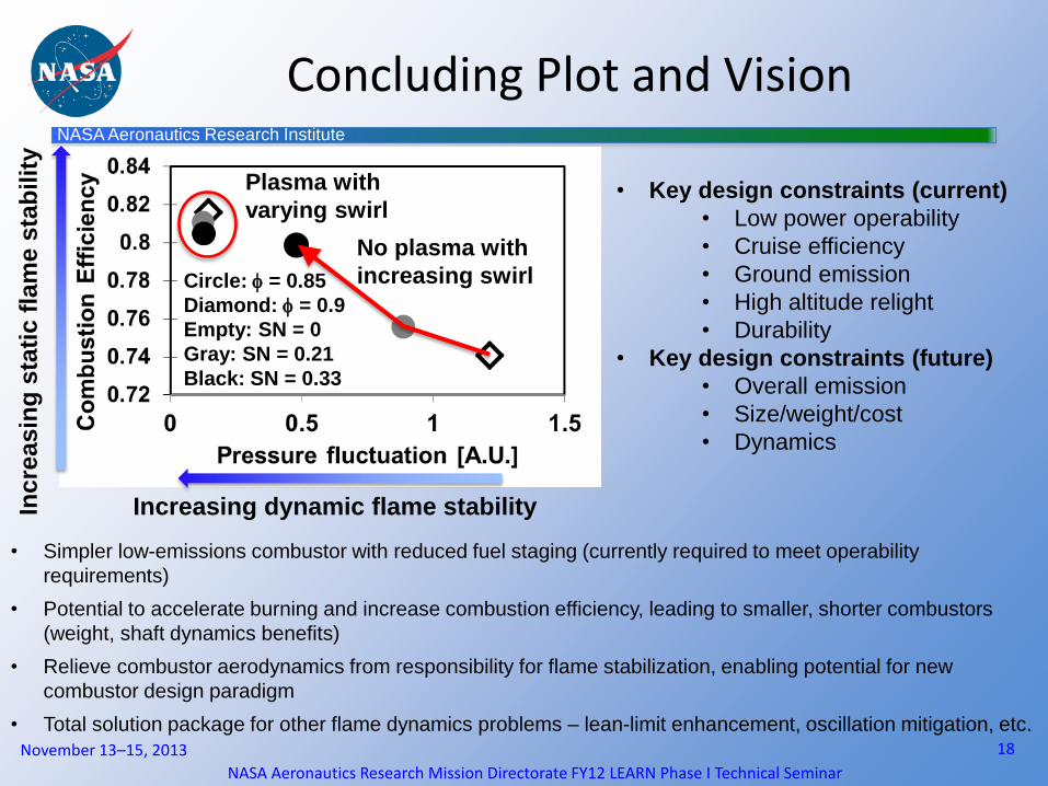
Concluding Plot and Vision
NASA Aeronautics Research Mission Directorate FY12 LEARN Phase I Technical Seminar
18
• Key design constraints (current)
• Low power operability
• Cruise efficiency
• Ground emission
• High altitude relight
• Durability
• Key design constraints (future)
• Overall emission
• Size/weight/cost
• Dynamics
November 13–15, 2013
No plasma with
increasing swirl Circle: f = 0.85
Diamond: f = 0.9
Empty: SN = 0
Gray: SN = 0.21
Black: SN = 0.33
Plasma with
varying swirl
Inc
rea
sin
g s
tati
c f
lam
e s
tab
ilit
y
Increasing dynamic flame stability
• Simpler low-emissions combustor with reduced fuel staging (currently required to meet operability
requirements)
• Potential to accelerate burning and increase combustion efficiency, leading to smaller, shorter combustors
(weight, shaft dynamics benefits)
• Relieve combustor aerodynamics from responsibility for flame stabilization, enabling potential for new
combustor design paradigm
• Total solution package for other flame dynamics problems – lean-limit enhancement, oscillation mitigation, etc.

NASA Aeronautics Research Institute
Distribution/Dissemination Plan
NASA Aeronautics Research Mission Directorate FY12 LEARN Phase I Technical Seminar
19
• Final report: Before 3 month after the contract end
• Publication (planning) : 35th International Symposium on Combustion (The
proceedings of the Combustion Institute) or Combustion and Flame
November 13–15, 2013

NASA Aeronautics Research Institute
Next Steps
NASA Aeronautics Research Mission Directorate FY12 LEARN Phase I Technical Seminar
20
• Remaining step for phase I (in case
no-cost-extension is permitted) Simultaneous OH PLIF and PIV to
investigate flame/flow structure
interaction
a key step to verify the mechanism
proposed in this presentation
• Key objective for Phase II: Demonstrating similar level of plasma effect at more
realistic gas turbine combustor conditions
• Milestones for Phase II Intermediate step: Higher flow (~ 100 m/s) at ambient T, P
with methane fuel
High T test: T3 up to ~1150 F at atmospheric P with
vaporized Jet A fuel
High T/P test: T3 (up to ~1150F) and P4 (up to 250 Psia)
with vaporized Jet A fuel
Realistic fuel test: liquid Jet A
Sadanandan et al.,
2008 (Applied
Physic B 90, 609-
618)
inlet
plenum
test-section
w/ windows
torch
igniter
airflow
flow-
straightener
baffle
Primary
injection
Secondary
injectionEmissions
probe
November 13–15, 2013