pillar fire hydrant apollo series - rensberg catalogue...4 the csa pillar fire hydrant apollo...
TRANSCRIPT
Pillar fire hydrant Apollo series
2
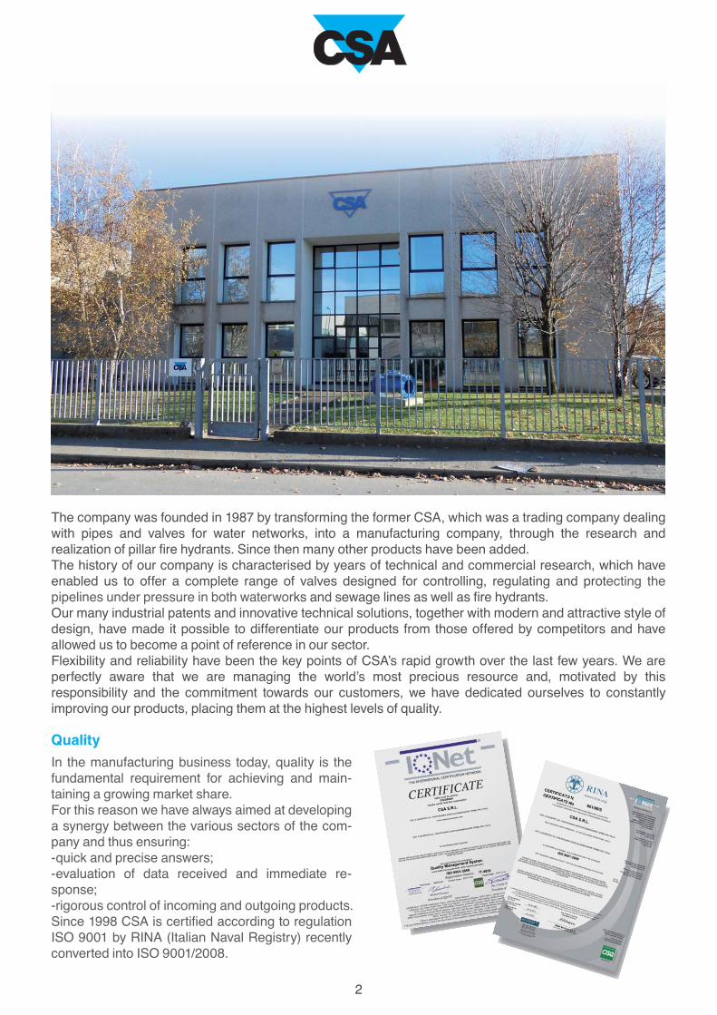
The company was founded in 1987 by transforming the former CSA, which was a trading company dealing
with pipes and valves for water networks, into a manufacturing company, through the research and
realization of pillar fire hydrants. Since then many other products have been added.
The history of our company is characterised by years of technical and commercial research, which have
enabled us to offer a complete range of valves designed for controlling, regulating and protecting the
pipelines under pressure in both waterworks and sewage lines as well as fire hydrants.
Our many industrial patents and innovative technical solutions, together with modern and attractive style of
design, have made it possible to differentiate our products from those offered by competitors and have
allowed us to become a point of reference in our sector.
Flexibility and reliability have been the key points of CSA’s rapid growth over the last few years. We are
perfectly aware that we are managing the world’s most precious resource and, motivated by this
responsibility and the commitment towards our customers, we have dedicated ourselves to constantly
improving our products, placing them at the highest levels of quality.
Quality
In the manufacturing business today, quality is the
fundamental requirement for achieving and main-
taining a growing market share.
For this reason we have always aimed at developing
a synergy between the various sectors of the com-
pany and thus ensuring:
-quick and precise answers;
-evaluation of data received and immediate re-
sponse;
-rigorous control of incoming and outgoing products.
Since 1998 CSA is certified according to regulation
ISO 9001 by RINA (Italian Naval Registry) recently
converted into ISO 9001/2008.
3
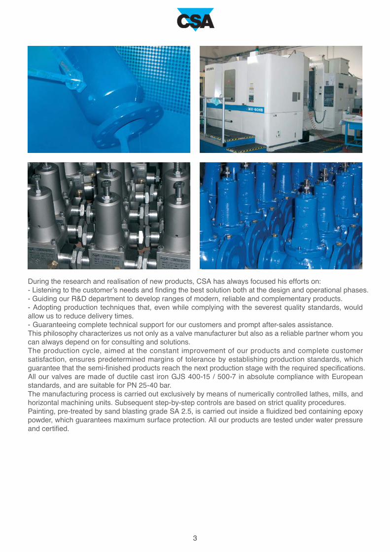
During the research and realisation of new products, CSA has always focused his efforts on:
- Listening to the customer’s needs and finding the best solution both at the design and operational phases.
- Guiding our R&D department to develop ranges of modern, reliable and complementary products.
- Adopting production techniques that, even while complying with the severest quality standards, would
allow us to reduce delivery times.
- Guaranteeing complete technical support for our customers and prompt after-sales assistance.
This philosophy characterizes us not only as a valve manufacturer but also as a reliable partner whom you
can always depend on for consulting and solutions.
The production cycle, aimed at the constant improvement of our products and complete customer
satisfaction, ensures predetermined margins of tolerance by establishing production standards, which
guarantee that the semi-finished products reach the next production stage with the required specifications.
All our valves are made of ductile cast iron GJS 400-15 / 500-7 in absolute compliance with European
standards, and are suitable for PN 25-40 bar.
The manufacturing process is carried out exclusively by means of numerically controlled lathes, mills, and
horizontal machining units. Subsequent step-by-step controls are based on strict quality procedures.
Painting, pre-treated by sand blasting grade SA 2.5, is carried out inside a fluidized bed containing epoxy
powder, which guarantees maximum surface protection. All our products are tested under water pressure
and certified.
4
The CSA pillar fire hydrant Apollo series, designed in conformity with the applicable European standards,
is composed of three models entirely manufactured in ductile cast iron and stainless steel with technical
features to reach the highest standards in product safety and quality. Their design, production process and
performances contribute to create a reliable product proudly made in Italy.
Pillar fire hydrant Apollo series
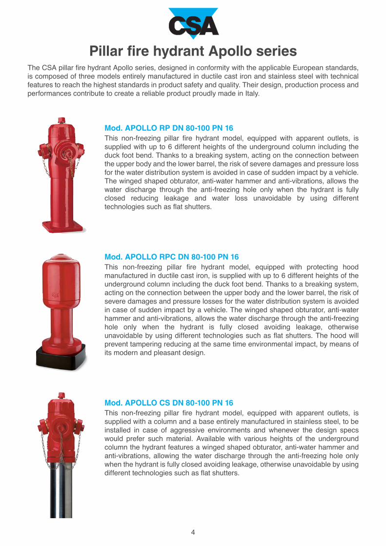
Mod. APOLLO RP DN 80-100 PN 16This non-freezing pillar fire hydrant model, equipped with apparent outlets, is
supplied with up to 6 different heights of the underground column including the
duck foot bend. Thanks to a breaking system, acting on the connection between
the upper body and the lower barrel, the risk of severe damages and pressure loss
for the water distribution system is avoided in case of sudden impact by a vehicle.
The winged shaped obturator, anti-water hammer and anti-vibrations, allows the
water discharge through the anti-freezing hole only when the hydrant is fully
closed reducing leakage and water loss unavoidable by using different
technologies such as flat shutters.
Mod. APOLLO RPC DN 80-100 PN 16This non-freezing pillar fire hydrant model, equipped with protecting hood
manufactured in ductile cast iron, is supplied with up to 6 different heights of the
underground column including the duck foot bend. Thanks to a breaking system,
acting on the connection between the upper body and the lower barrel, the risk of
severe damages and pressure losses for the water distribution system is avoided
in case of sudden impact by a vehicle. The winged shaped obturator, anti-water
hammer and anti-vibrations, allows the water discharge through the anti-freezing
hole only when the hydrant is fully closed avoiding leakage, otherwise
unavoidable by using different technologies such as flat shutters. The hood will
prevent tampering reducing at the same time environmental impact, by means of
its modern and pleasant design.
Mod. APOLLO CS DN 80-100 PN 16This non-freezing pillar fire hydrant model, equipped with apparent outlets, is
supplied with a column and a base entirely manufactured in stainless steel, to be
installed in case of aggressive environments and whenever the design specs
would prefer such material. Available with various heights of the underground
column the hydrant features a winged shaped obturator, anti-water hammer and
anti-vibrations, allowing the water discharge through the anti-freezing hole only
when the hydrant is fully closed avoiding leakage, otherwise unavoidable by using
different technologies such as flat shutters.

5
1
3
3
1
1
7
1
2
5
4
2
6
Technical features
1. Overall paintingTo guarantee the best resistance against corrosion and in compliance with potable water requirements all
CSA hydrants are subject to internal and external painting, more precisely black or blue RAL 5005 epoxy
powders for the underground barrel and red polyester RAL 3000 for the upper body (above ground).
2. Internal components in stainless steel
All internals are manufactured in stainless steel and pro-
tected from contact with the ductile iron by means of compo-
nents in bronze and brass.
3. Anti-friction technology
All components involved in the movement and rotation are
designed to reduce friction and interferences as much as
possible, in addition to innovative technical solutions, in order
to reduce torque and excessive wearing.
4. Obturator anti-water hammer and anti-vibration (see
page 7)
5. Anti-freezing drainage hole
In case of low temperatures with risk of frost it is necessary to
allow the complete drainage of the hydrant once the closed
position has been reached. CSA manufactures all hydrants
with anti-freezing drainage hole obtained on the sealing ring,
onto which the rubber coating of the obturator is acting, em-
bedded inside the base either supplied with a duck foot bend
or vertical connection.
6. Breaking system (see page 6)
7. Safety system of the obturator
The water tightness on CSA hydrants is obtained by the com-
pression of the rubber coating of the obturator, made in duc-
tile cast iron, against the sealing ring housed inside the lower
base either supplied as a duck foot bend or vertical connec-
tion. This solution avoids excessive wearing and frequent
maintenance, as well as reducing the torque necessary for
the complete closure. Should the latter be excessive, an inno-
vative construction detail will prevent under any circumstan-
ces any possible damage to the obturator mobile block.
6
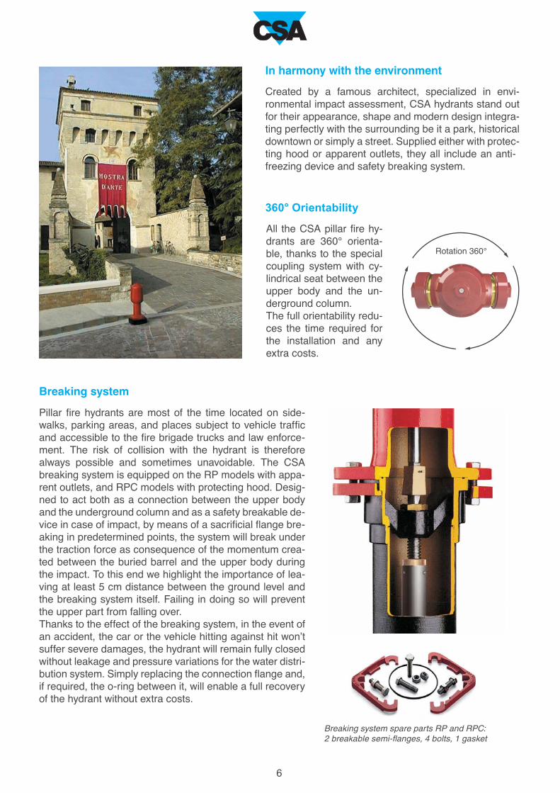
In harmony with the environment
Created by a famous architect, specialized in envi-
ronmental impact assessment, CSA hydrants stand out
for their appearance, shape and modern design integra-
ting perfectly with the surrounding be it a park, historical
downtown or simply a street. Supplied either with protec-
ting hood or apparent outlets, they all include an anti-
freezing device and safety breaking system.
360° Orientability
Breaking system
Pillar fire hydrants are most of the time located on side-
walks, parking areas, and places subject to vehicle traffic
and accessible to the fire brigade trucks and law enforce-
ment. The risk of collision with the hydrant is therefore
always possible and sometimes unavoidable. The CSA
breaking system is equipped on the RP models with appa-
rent outlets, and RPC models with protecting hood. Desig-
ned to act both as a connection between the upper body
and the underground column and as a safety breakable de-
vice in case of impact, by means of a sacrificial flange bre-
aking in predetermined points, the system will break under
the traction force as consequence of the momentum crea-
ted between the buried barrel and the upper body during
the impact. To this end we highlight the importance of lea-
ving at least 5 cm distance between the ground level and
the breaking system itself. Failing in doing so will prevent
the upper part from falling over.
Thanks to the effect of the breaking system, in the event of
an accident, the car or the vehicle hitting against hit won’t
suffer severe damages, the hydrant will remain fully closed
without leakage and pressure variations for the water distri-
bution system. Simply replacing the connection flange and,
if required, the o-ring between it, will enable a full recovery
of the hydrant without extra costs.
Breaking system spare parts RP and RPC:2 breakable semi-flanges, 4 bolts, 1 gasket
Rotation 360°
All the CSA pillar fire hy-
drants are 360° orienta-
ble, thanks to the special
coupling system with cy-
lindrical seat between the
upper body and the un-
derground column.
The full orientability redu-
ces the time required for
the installation and any
extra costs.

7
1
3
2
4
Obturator
The CSA obturator, manufactured in ductile cast iron fully
coated with NBR vulcanized or EPDM, is a winged shaped
cone performing a perfect water tightness by means of the
compression of its cylindrical part against the sealing ring
housed inside the base of the hydrant, either duck foot bend or
vertical connection. The coating is applied on three different
layers where the one in the middle closes the anti-freezing
drainage hole, while the two remaining will prevent any kind of
vibration.
This design allows:
-a water tightness in presence of high pressure values, even
higher than 25 bar;
-the absence of any kind of interference with foreign materials
that can enter the hydrant;
-a gradual variation of low and pressure during opening and
closing, preventing unwanted water hammer events and/or
sudden drop in pressure.
Water leakage and loss reduction. The winged shaped obturator will avoid, under any circumstances, to
put in communication the drainage anti-freezing hole with the upstream pressure, which is happening all
the time during the usage of the hydrant and the manoeuvers with flat disks and technologies not equiva-
lent to CSA. When that occurs huge amounts of water are wasted through concealed water loss.
Operating principle
1. Obturator to the fully closed posi-tion. Perfect water tightness with the
drainage anti-freezing hole fully open.
Water trapped inside the pillar fire
hydrant pours out of the drainage hole
avoiding possible damages caused by
frost.
2. Obturator to the initial opening phase. Perfect water tightness. The
drainage hole is closed before putting
the upstream pressure in communica-
tion with the hydrant.
3. Obturator to the intermediate ope-ning phase. Flow rate increasing
gradually. The drainage hole is always
closed as the obturator is progressing
upwards.
4. Obturator to the fully open posi-tion. Flow rate through the hydrant and
to the outlets has reached the maxi-
mum value, the drainage anti-freezing
hole is always closed. Absence of vibra-
tions thanks to the winged shaped obtu-
rator.

8
The CSA pillar fire hydrant Mod. Apollo RP is composed of an upper body and an underground part,
entirely made in ductile cast iron and stainless steel, joined together by a breakable system activated in
case of impact of a vehicle. Designed in keeping with the applicable European standards this model featu-
res apparent outlets and an exclusive anti-leakage and surge prevention vibration proof obturator, housed
inside the duck foot bend supplied as a standard with the hydrant.
Pillar fire hydrantMod. Apollo RP
Technical features and benefits
Upper body in ductile cast iron GJS 500/7 PN 16 bar rated, red RAL 3000 polyester powder coated for
the maximum resistance to UVA exposure.
Underground part composed of duck foot bend, barrel, driving box, adjustable flanges entirely made in
ductile cast iron black or blue epoxy paint coated.
Exclusive CSA breaking system simple and reliable.
Pentagonal caps machined to avoid and limit as much as possible unauthorized water consumption.
Anti-freezing device.
Internals in stainless steel to increase resistance to corrosion, safety and performances over time.
Exclusive winged shaped obturator, with core in ductile cast iron NBR or EPDM coated to avoid water
hammer effect during opening and closing, minimize vibrations during usage and prevent water loss
through the anti-freezing hole.
Sealing seat obtained by a ring threaded directly inside the CSA duck foot bend, supplied as a standard
with the hydrant and designed to reduce head loss and avoid damages also in case of stones, debris
coming through the hydrant.
The operating female screw pinned directly to the stand pipe for the highest resistance and safety.

A
mm
B
mm
C
mm
D
mm
H
mm
D
B
A
H
9
RP 100D
RP 100C
RP 100B
RP 100A
RP 100X
2230
2030
1830
1590
1490
+
2Ø70
1Ø100
750 50
1430
1230
1030
790
690
180
86
81
76
70
65
DN 100
RP 80D
RP 80C
2195
1995
1440
1240
63
60
RP 80A
RP 80X
RP 80B
1555
1445
800
690
1765 2Ø70705 501010 130
52
49
56DN 80
8
6
14
11 2 3 4 9 10
16
17
21
18
23
19
15
13
22
30
27
36
35
38
39
29
12
7
16
15
13
14
1
5
20
19
37
32
33
34
25
24
12
26
28
31
1
2
3
4
5
6
7
8
9
10
11
12
13
14
15
16
17
18
19
20
21
22
23
24
25
26
27
28
29
30
31
32
33
34
35
36
37
38
39
N.
C
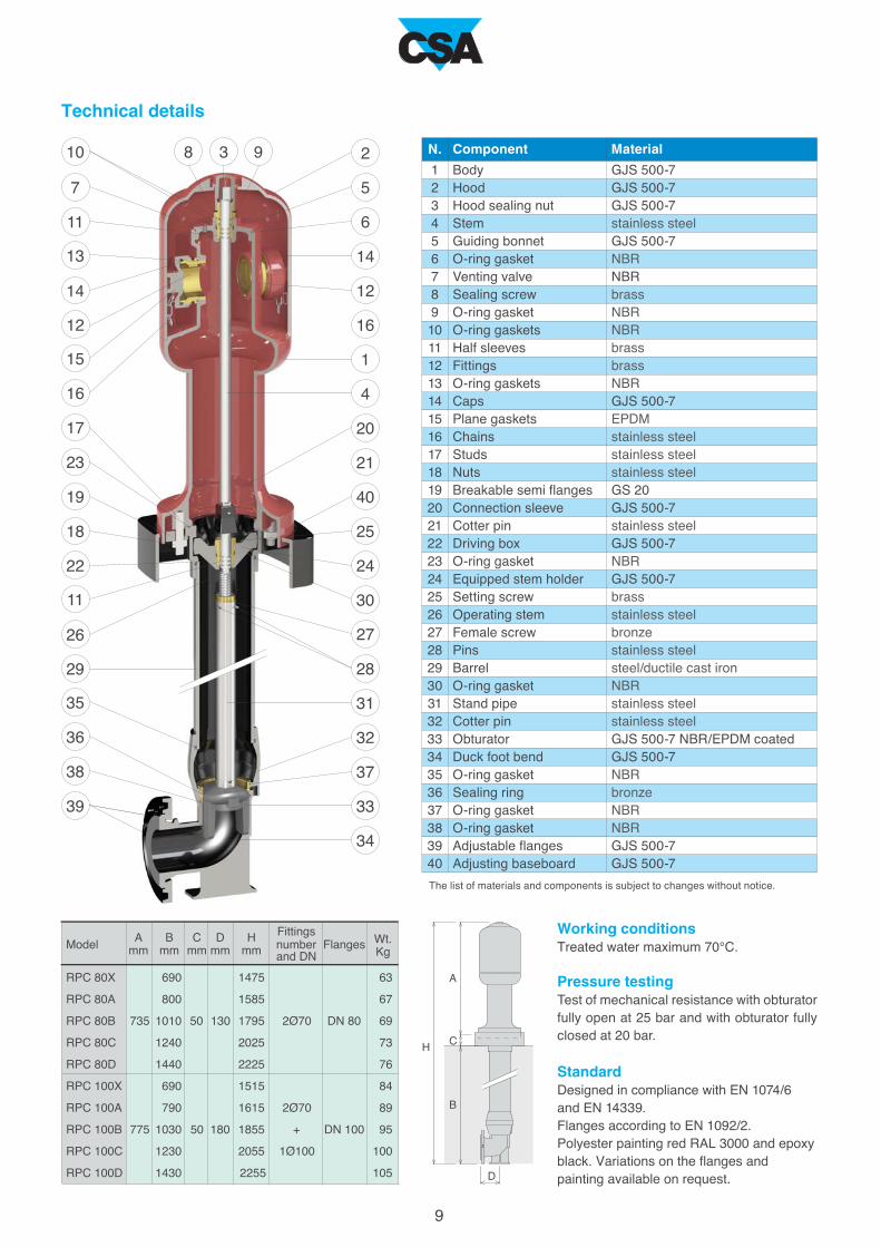
Technical details
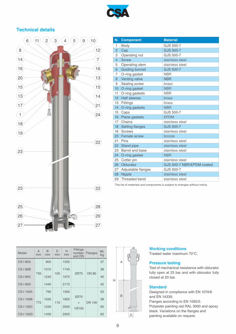
Working conditionsTreated water maximum 70°C.
StandardDesigned in compliance with EN 1074/6
and EN 14339.
Flanges according to EN 1092/2.
Polyester painting red RAL 3000 and epoxy
black. Variations on the flanges and
painting available on request.
Body
Cap
Operating nut
Screw
Stem
Guiding bonnet
O-ring gasket
Venting valve
Sealing screw
O-ring gasket
O-ring gaskets
Half sleeves
Fittings
O-ring gaskets
Caps
Plane gaskets
Chains
Screws and nuts
Breakable semi-flanges
Connection sleeve
Cotter pin
Driving box
O-ring gasket
Equipped stem holder
Setting screw
Operating stem
Female screw
Pins
Barrel
O-ring gasket
Stand pipe
Cotter pin
Obturator
Duck foot bend
O-ring gasket
Sealing ring
O-ring gasket
O-ring gasket
Adjustable flanges
GJS 500-7
GJS 500-7
GJS 500-7
stainless steel
stainless steel
GJS 500-7
NBR
NBR
brass
NBR
NBR
brass
brass
NBR
GJS 500-7
EPDM
stainless steel
stainless steel
GS 20
GJS 500-7
stainless steel
GJS 500-7
NBR
GJS 500-7
brass
stainless steel
bronze
stainless steel
steel/ductile cast iron
NBR
stainless steel
stainless steel
GJS 500-7 NBR/EPDM coated
GJS 500-7
NBR
bronze
NBR
NBR
GJS 500-7
Component Material
The list of materials and components is subject to changes without notice.
Wt.
Kg
FlangesModel
and DN
number
Fittings
Pressure testingTest of mechanical resistance with obturator
fully open at 25 bar and with obturator fully
closed at 20 bar.
10
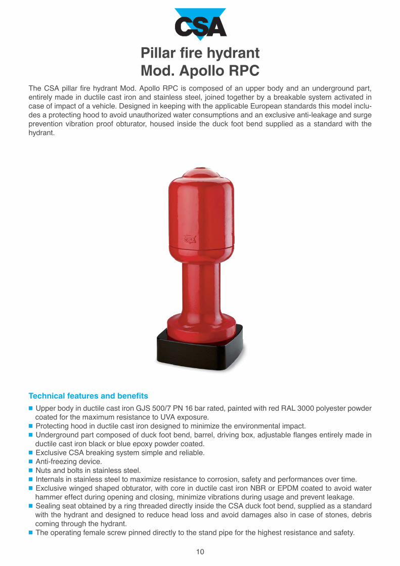
Pillar fire hydrantMod. Apollo RPC
The CSA pillar fire hydrant Mod. Apollo RPC is composed of an upper body and an underground part,
entirely made in ductile cast iron and stainless steel, joined together by a breakable system activated in
case of impact of a vehicle. Designed in keeping with the applicable European standards this model inclu-
des a protecting hood to avoid unauthorized water consumptions and an exclusive anti-leakage and surge
prevention vibration proof obturator, housed inside the duck foot bend supplied as a standard with the
hydrant.
Technical features and benefits
Upper body in ductile cast iron GJS 500/7 PN 16 bar rated, painted with red RAL 3000 polyester powder
coated for the maximum resistance to UVA exposure.
Protecting hood in ductile cast iron designed to minimize the environmental impact.
Underground part composed of duck foot bend, barrel, driving box, adjustable flanges entirely made in
ductile cast iron black or blue epoxy powder coated.
Exclusive CSA breaking system simple and reliable.
Anti-freezing device.
Nuts and bolts in stainless steel.
Internals in stainless steel to maximize resistance to corrosion, safety and performances over time.
Exclusive winged shaped obturator, with core in ductile cast iron NBR or EPDM coated to avoid water
hammer effect during opening and closing, minimize vibrations during usage and prevent leakage.
Sealing seat obtained by a ring threaded directly inside the CSA duck foot bend, supplied as a standard
with the hydrant and designed to reduce head loss and avoid damages also in case of stones, debris
coming through the hydrant.
The operating female screw pinned directly to the stand pipe for the highest resistance and safety.
A
mm
B
mm
C
mm
D
mm
H
mm
D
B
A
CH
9
+
2Ø70
1Ø100
50
1430
1230
1030
790
690
180 DN 100
1440
1240
800
690
2Ø70501010 130 DN 80
11
7
13
10 3 98 2
14
16
17
23
19
18
15
12
22
11
26
36
38
39
35
29
5
6
14
12
16
1
4
20
21
37
33
34
25
40
24
30
27
28
31
32
RPC 80X
RPC 80A
RPC 100X
RPC 80D
RPC 100C
RPC 100B
RPC 100A
RPC 100D
RPC 80C
RPC 80B 735
775
2255
2055
1855
1615
1515
2225
2025
1795
1585
1475
95
89
84
76
73
69
67
63
105
100
1
2
3
4
5
6
7
8
9
10
11
12
13
14
15
16
17
18
19
20
21
22
23
24
25
26
27
28
29
30
31
32
33
34
35
36
37
38
39
40
N.
Technical details
Body
Hood
Hood sealing nut
Stem
Guiding bonnet
O-ring gasket
Venting valve
Sealing screw
O-ring gasket
O-ring gaskets
Half sleeves
Fittings
O-ring gaskets
Caps
Plane gaskets
Chains
Studs
Nuts
Breakable semi flanges
Connection sleeve
Cotter pin
Driving box
O-ring gasket
Equipped stem holder
Setting screw
Operating stem
Female screw
Pins
Barrel
O-ring gasket
Stand pipe
Cotter pin
Obturator
Duck foot bend
O-ring gasket
Sealing ring
O-ring gasket
O-ring gasket
Adjustable flanges
Adjusting baseboard
GJS 500-7
GJS 500-7
GJS 500-7
stainless steel
GJS 500-7
NBR
NBR
brass
NBR
NBR
brass
brass
NBR
GJS 500-7
EPDM
stainless steel
stainless steel
stainless steel
GS 20
GJS 500-7
stainless steel
GJS 500-7
NBR
GJS 500-7
brass
stainless steel
bronze
stainless steel
steel/ductile cast iron
NBR
stainless steel
stainless steel
GJS 500-7 NBR/EPDM coated
GJS 500-7
NBR
bronze
NBR
NBR
GJS 500-7
GJS 500-7
Component Material
The list of materials and components is subject to changes without notice.
Wt.
Kg
FlangesModel
and DN
number
Fittings Working conditionsTreated water maximum 70°C.
StandardDesigned in compliance with EN 1074/6
and EN 14339.
Flanges according to EN 1092/2.
Polyester painting red RAL 3000 and epoxy
black. Variations on the flanges and
painting available on request.
Pressure testingTest of mechanical resistance with obturator
fully open at 25 bar and with obturator fully
closed at 20 bar.
12
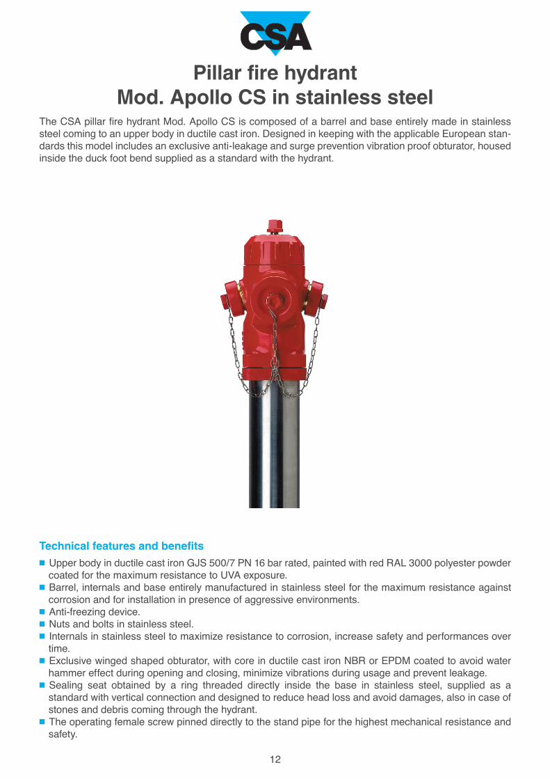
The CSA pillar fire hydrant Mod. Apollo CS is composed of a barrel and base entirely made in stainless
steel coming to an upper body in ductile cast iron. Designed in keeping with the applicable European stan-
dards this model includes an exclusive anti-leakage and surge prevention vibration proof obturator, housed
inside the duck foot bend supplied as a standard with the hydrant.
Pillar fire hydrantMod. Apollo CS in stainless steel
Technical features and benefits
Upper body in ductile cast iron GJS 500/7 PN 16 bar rated, painted with red RAL 3000 polyester powder
coated for the maximum resistance to UVA exposure.
Barrel, internals and base entirely manufactured in stainless steel for the maximum resistance against
corrosion and for installation in presence of aggressive environments.
Anti-freezing device.
Nuts and bolts in stainless steel.
Internals in stainless steel to maximize resistance to corrosion, increase safety and performances over
time.
Exclusive winged shaped obturator, with core in ductile cast iron NBR or EPDM coated to avoid water
hammer effect during opening and closing, minimize vibrations during usage and prevent leakage.
Sealing seat obtained by a ring threaded directly inside the base in stainless steel, supplied as a
standard with vertical connection and designed to reduce head loss and avoid damages, also in case of
stones and debris coming through the hydrant.
The operating female screw pinned directly to the stand pipe for the highest mechanical resistance and
safety.
A
mm
B
mm
D
mm
H
mm
D
B
A
H
9
+
2Ø70
1Ø100
DN 100
2Ø70 DN 80
14
8
6
16
11 2 3 4 5 9
20
17
1
18
19
13
15
23
25
26
27
23
10
7
12
16
13
15
14
21
24
29
28
27
22
22
CS-I 100D
CS-I 100C
CS-I 100B
CS-I 100A
110775
1430
1230
1030
790
CS-I 80D
CS-I 80C
1440
1240
CS-I 80B
CS-I 80A 800
100735
1010
62
60
58
53
42
40
2205
2005
1805
1565
2175
1975
38
371535
1745
1
2
3
4
5
6
7
8
9
10
11
12
13
14
15
16
17
18
19
20
21
22
23
24
25
26
27
28
29
N.
Technical details
The list of materials and components is subject to changes without notice.
Body
Cap
Operating nut
Screw
Operating stem
Guiding bonnet
O-ring gasket
Venting valve
Sealing screw
O-ring gasket
O-ring gaskets
Half sleeves
Fittings
O-ring gaskets
Caps
Plane gaskets
Chains
Setting flanges
Screws
Female screw
Pins
Stand pipe
Barrel and base
O-ring gasket
Cotter pin
Obturator
Adjustable flanges
Nipple
Threaded bend
GJS 500-7
GJS 500-7
GJS 500-7
stainless steel
stainless steel
GJS 500-7
NBR
NBR
brass
NBR
NBR
brass
brass
NBR
GJS 500-7
EPDM
stainless steel
GJS 500-7
stainless steel
bronze
stainless steel
stainless steel
stainless steel
NBR
stainless steel
GJS 500-7 NBR/EPDM coated
GJS 500-7
stainless steel
stainless steel
Component Material
Working conditionsTreated water maximum 70°C.
StandardDesigned in compliance with EN 1074/6
and EN 14339.
Flanges according to EN 1092/2.
Polyester painting red RAL 3000 and epoxy
black. Variations on the flanges and
painting available on request.
Pressure testingTest of mechanical resistance with obturator
fully open at 25 bar and with obturator fully
closed at 20 bar.
Wt.
Kg
FlangesModel
and DN
number
Fittings
B
A
A
mm
B
mm
PN
bar
100
80
16
12
16500 350
14
160
140
120
100
80
60
40
20
0 1 2 3 4 5 6 7 8 9 10
Kv (m
3/h
)
RP-RPC DN100
RP-RPC DN80
DN
mm
Weight
Kg
Accessori
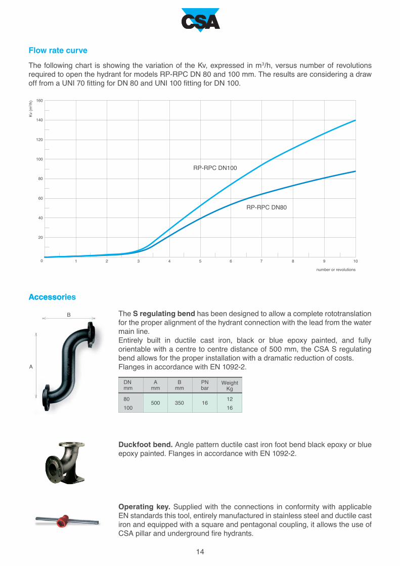
Operating key. Supplied with the connections in conformity with applicable
EN standards this tool, entirely manufactured in stainless steel and ductile cast
iron and equipped with a square and pentagonal coupling, it allows the use of
CSA pillar and underground fire hydrants.
number or revolutions
Accessories
The S regulating bend has been designed to allow a complete rototranslation
for the proper alignment of the hydrant connection with the lead from the water
main line.
Entirely built in ductile cast iron, black or blue epoxy painted, and fully
orientable with a centre to centre distance of 500 mm, the CSA S regulating
bend allows for the proper installation with a dramatic reduction of costs.
Flanges in accordance with EN 1092-2.
Duckfoot bend. Angle pattern ductile cast iron foot bend black epoxy or blue
epoxy painted. Flanges in accordance with EN 1092-2.
Flow rate curve
The following chart is showing the variation of the Kv, expressed in m3/h, versus number of revolutions
required to open the hydrant for models RP-RPC DN 80 and 100 mm. The results are considering a draw
off from a UNI 70 fitting for DN 80 and UNI 100 fitting for DN 100.
1515
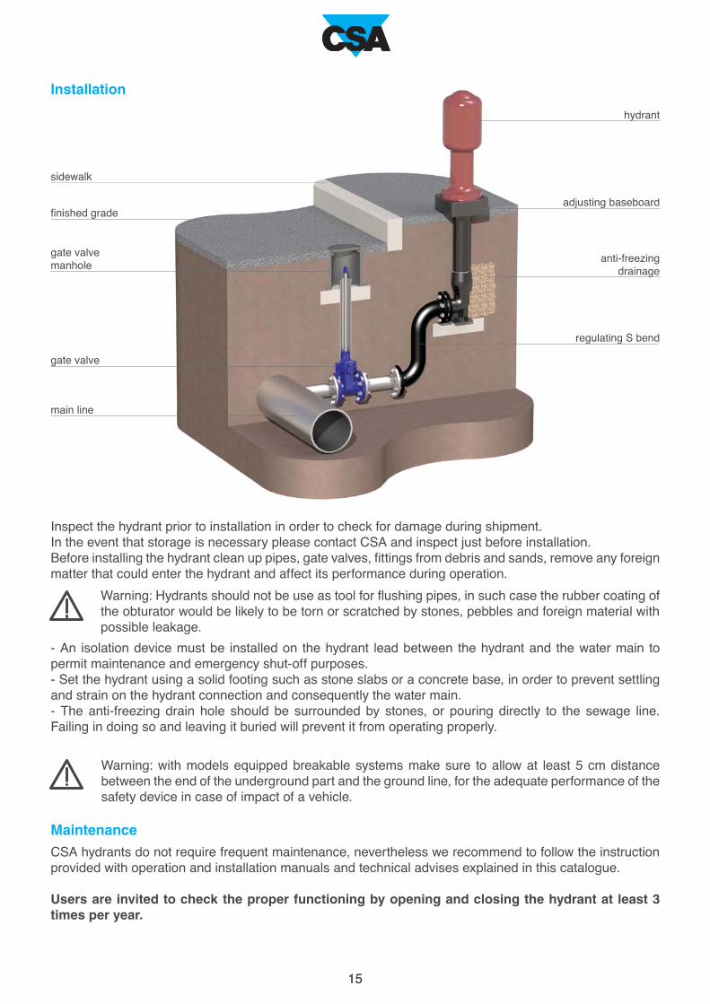
Installation
Maintenance
CSA hydrants do not require frequent maintenance, nevertheless we recommend to follow the instruction
provided with operation and installation manuals and technical advises explained in this catalogue.
Users are invited to check the proper functioning by opening and closing the hydrant at least 3 times per year.
Inspect the hydrant prior to installation in order to check for damage during shipment.
In the event that storage is necessary please contact CSA and inspect just before installation.
Before installing the hydrant clean up pipes, gate valves, fittings from debris and sands, remove any foreign
matter that could enter the hydrant and affect its performance during operation.
- An isolation device must be installed on the hydrant lead between the hydrant and the water main to
permit maintenance and emergency shut-off purposes.
- Set the hydrant using a solid footing such as stone slabs or a concrete base, in order to prevent settling
and strain on the hydrant connection and consequently the water main.
- The anti-freezing drain hole should be surrounded by stones, or pouring directly to the sewage line.
Failing in doing so and leaving it buried will prevent it from operating properly.
Warning: Hydrants should not be use as tool for flushing pipes, in such case the rubber coating of
the obturator would be likely to be torn or scratched by stones, pebbles and foreign material with
possible leakage.
Warning: with models equipped breakable systems make sure to allow at least 5 cm distance
between the end of the underground part and the ground line, for the adequate performance of the
safety device in case of impact of a vehicle.
sidewalk
finished grade
gate valve
manhole
main line
gate valve
hydrant
anti-freezing
drainage
adjusting baseboard
regulating S bend

CSA s.r.l. - Strada San Giuseppe, 15 - località Ponteghiara
43039 Salsomaggiore Terme (PR) - Italy
TEL. +39.0524.523978 - FAX +39.0524.524031
www.csasrl.it - [email protected]