photovoltaic array wiring handbook for - · pdf filephotovoltaic array wiring handbook for...
TRANSCRIPT

BP SOLAREX WIRE HDBK, 21 APRIL 2000
PHOTOVOLTAIC ARRAY WIRING HANDBOOK FOR STANDARD NOMINAL 6, 12, 24, AND 48 VOLT SYSTEMS (for SX-60 series or smaller and MSX-120 solar modules) COPYRIGHT INFORMATION BP Solarex holds all copyrights for this manual. No part of this publication may be reproduced or transmitted in any form without permission in writing from BP Solarex. NOTE The information given in this booklet is intended to provide the end installer with the instructions to wire the PV system. It is mandatory that the installer follow all of the state or local codes that apply to the actual PV system. BP Solarex 630 Solarex Court Frederick MD 21703 Telephone: 301-698-4200 Facsimile: 301-698-4201 Printed in U.S.A. PART NUMBER 42500066/E

BP SOLAREX WIRE HDBK, 21 APRIL 2000
i
TABLE OF CONTENTS TITLE PAGE TABLE OF CONTENTS i 1.0 INTRODUCTION 1 2.0 BASIC SYSTEM WIRING PRINCIPLES 2 2.1 Module Wiring 2 2.2 Blocking Diodes 4 2.3 Bypass Diodes 5 2.4 Intermodule Wiring 5 2.5 Interpanel Wiring 6 2.6 Output Wiring 6 2.7 Surge Protection 6 2.8 Regulator to Battery Cable 7 2.9 Typical System Wiring 8 3.0 PROCEDURES FOR ARRAY WIRING 12 3.1 Recommended Wiring Color Use 14 3.2 Grounding (If Applicable) 14 APPENDIX A AMERICAN/METRIC WIRE GAUGES A-1 VOLTAGE DROP FOR 10 AMPS CURRENT AT 100 FOOT DISTANCE A-2 APPENDIX B REPLACEMENT PARTS ORDERING INFORMATION B-1
TABLES TABLE TITLE PAGE 1 BLOCKING DIODES 4 2 BYPASS DIODES 5 3 REGULATOR TO BATTERY CABLE UP TO 30 AMPS AT 75ºC 7 4 REGULATOR TO BATTERY CABLE 30 AMPS TO 200 AMPS AT 75ºC 8
FIGURES AND DRAWINGS FIGURE TITLE PAGE 1 MODULE WIRING 3 2 TYPICAL SYSTEM SCHEMATIC WITH AN ACR-II/30A 9 3 TYPICAL SYSTEM SCHEMATIC WITH AN ACR-II/90A 10 4 TYPICAL SYSTEM SCHEMATIC WITH AN ACR-200A 11 5 ALARM BOARD OPTION DETAIL 12 DRAWING TITLE WKS206*** 6V BASIC WIRING SYSTEMS WKS212*** 12V BASIC WIRING SYSTEMS WKS224*** 24V BASIC WIRING SYSTEMS WKS248*** 48V BASIC WIRING SYSTEMS

BP SOLAREX WIRE HDBK, 21 APRIL 2000
1
1.0 INTRODUCTION This handbook is intended for use in the installation of basic (standard) photovoltaic (PV) systems. The primary purpose of the Solarex standard Module PV array is to produce current, at specified nominal voltages, up to a maximum of 20 Amperes. As the Module (SX-60 series) produces up to a nominal 8.0 Amps Short-circuit current (Isc) when wired for a nominal 6 volts at Standard Test Conditions (STC) or 4.0 Amps Isc when wired for a nominal 12 volts, the number of modules required to produce the maximum current for each voltage system is: 6-volts, two modules; 12-volts, five modules; 24-volts, 10 modules; and 48-volts, 20 modules. Larger systems can be provided for specific requirements. The length of cable from the array to the regulator is critical. Too long a cable will cause unacceptable losses in the specified parameters of the array. The same is true for battery and load cables. NOTE: Standard Test Conditions - Illumination of 1kW/m2 (1 sun)
at spectral distribution of AM 1.5 and cell temperature at 25°C. A description of the system wiring concept and terminology is provided along with component descriptions and instructions for wiring a basic 6 volt, 12 volt, 24 volt, or 48 volt system. (See drawings WKS206*** through WKS248***) Personnel installing the system should read this handbook thoroughly before attempting to wire the system. Personnel must study this handbook in detail and have a clear understanding of the system to avoid damage and injury. All applicable local or state codes (such as the National Electric Code (N.E.C.) for the U.S.A.) should be followed in all aspects and should override if different from instructions given in this booklet.

BP SOLAREX WIRE HDBK, 21 APRIL 2000
2
2.0 BASIC SYSTEM WIRING PRINCIPLES
This section discusses the basic wiring principles and defines the wiring terminology, which applies to all Module system nominal voltages (6, 12, 24, and 48). The intent of this section is to provide persons installing the system with a basic understanding of the wiring systems so that the installation procedures can be more easily comprehended. Each module J-box is wired in series or parallel with connecting modules in accordance with its position in respect to other modules, panels, or the output. A wiring kit is provided for each required inter-module, inter-panel, and output connection as specified. Refer to drawings WKS206*** through WKS248*** for detail of parts supplied with each specific system identified by the voltage requirement and number of modules.
2.1 Module Wiring. All Solarex standard modules contain two
strings of cells, each producing a nominal six volt output. These strings are pre-wired into their respective Junction boxes (J-boxes) at the factory. Positive (red) leads are connected to terminals 2 and 3 of the J-box. Negative (gray) leads are connected to terminals 4 and 5 of the J-box. For 6 volt operation, terminals 2 and 3, and 4 and 5 are jumpered to provide a parallel output. For 12 volt operation, terminals 3 and 4 are jumpered to provide a series output. Module Junction box wiring and a simplified schematic of the module wiring is shown in Figure 1.

BP SOLAREX WIRE HDBK, 21 APRIL 2000
3
Positions #1 and #6 are not internally connected and are intended to be used for series parallel intermodule/panel connections. FIGURE 1. MODULE WIRING

BP SOLAREX WIRE HDBK, 21 APRIL 2000
4
2.2 Blocking Diodes. Because the PV array only produces voltages during daylight hours, blocking diodes are inserted in the circuits to prevent the batteries from discharging through the array during night time hours or anytime that the array is not producing current. Blocking diodes are placed in each module string for nominal 6 volt and 12 volt configurations. One blocking diode is used for each two modules wired in series, for a nominal 24 volt system and one blocking diode is used for each four modules wired in series, for a nominal 48 volt system (refer to Table 1). For SX-60 series and smaller modules, use the following table as a guide for blocking diode selection. TABLE 1. BLOCKING DIODES
SYSTEM VOLTAGE
QUANTITY BLOCKING DIODE
RATING
OR EQUIVALENT
SOLAREX PART NO.
6V Nominal 2 Per Module
5A, 40V, SR504
WK2BD-40
12V Nominal 1 Per Module
5A, 40V, SR504
WK2BD-40
24V Nominal 1 Per Series String
5A, 40V, SR-504
WK2BD-40
48V Nominal 1 Per Series String
6A, 400V, MR-754
WK2BD-400
Above 48V. Not to exceed 600V actual
1 Per Series String
6A, 1000V, MR-760
22200004

BP SOLAREX WIRE HDBK, 21 APRIL 2000
5
2.3 Bypass Diodes. The actual electrical characteristics of Solarex's Mega Cells are such that there is no need for by-pass diodes in 6, 12, or 24 Volt nominal systems in normal operation. It would however, be recommended to include by-pass diodes in these systems for very specific applications such as directly driven motors that are subject to very high starting torque’s. Please contact the factory for information on these types of specific applications. Note that by-pass diodes are mandatory for all systems with more than two modules in series i.e., 36V, 48V, 96V, 120V, etc. One bypass diode is mandatory, wired in parallel, with each 18 cell string (two diodes for 12V, SX-30 through SX-64). TABLE 2. BYPASS DIODES
SYSTEM VOLTAGE
QUANTITY BYPASS DIODE
RATING
OR EQUIVALENT
SOLAREX PART NO.
6V, 12V, 24V Nominal
Not Required
N/A
N/A
ABOVE Nominal 24V, NOT to exceed 600V actual
2 Per Module
6A, 400V, MR-754
WK2BPD
2.4 Intermodule Wiring. This refers to the connecting wires between modules of a panel. This connection can be either series or parallel. The wire utilized is #10 (6mm2) XHHW-2 with black representing the negative polarity and red representing the positive polarity. The white wire represents a conductor used to connect modules together in series.

BP SOLAREX WIRE HDBK, 21 APRIL 2000
6
2.5 Interpanel Wiring. This refers to the connecting wires
between panels of a subarray. The wire utilized is #10 (6mm2) XHHW-2 with black representing the negative polarity and red representing the positive polarity.
2.6 Output Wiring. Output wiring refers to the connecting wires
from the output module junction box to the system controller/regulator or battery bank. The output cable may be provided with the system and is cut to specific lengths for optimum operation of the system. The length of cable should be no more than the maximum length allowed. Use of longer cabling or adding cable to that already provided by splicing will cause degraded system operation. However, use of shorter lengths of cable is acceptable. Refer to drawings WKS206*** through WKS248*** for the maximum cable lengths allowed in specific systems. To accommodate the shortest distance for the output, it may be necessary for systems to be lay out with modules rotated 180o, outputs exiting from the left, etc. Attention must be given to keep the wiring scheme consistent with the basic wiring kit.
2.7 Surge Protection. A Metal Oxide Varistor (MOV) located on an
optional Add-On terminal provides protection against lightning-induced voltage spikes. The Add-On terminals are used optionally on the output wiring for use of cable larger than #10 AWG (6mm2) and not larger than #4 AWG (25mm2).

BP SOLAREX WIRE HDBK, 21 APRIL 2000
7
2.8 Regulator to Battery Cable The optimum "electrical" distances between the Regulator and the Battery Bank for the stated AWG wire gauges, using single conductor wire (one for positive and one for negative) for different currents are shown in Tables 1 and 2 for all four nominal system voltages (6, 12, 24, and 48 Volts); meters are rounded to + 0.1m. Distances shown are for single conductor wire only. Total wire required is times two (Positive and Negative). Recommended optimum "Not To Exceed" voltage drops are as follows: 6 Volt Nominal “0.04V” 12 Volt Nominal “0.08V” 24 Volt Nominal “0.16V” 48 Volt Nominal “0.32V” TABLE 3. REGULATOR TO BATTERY CABLE UP TO 30 AMPS AT 75ºC AWG 10 AMP 20 AMP 30 AMP NOMINAL WIRE MAXIMUM MAXIMUM MAXIMUM VOLTAGE GAUGE DISTANCE DISTANCE DISTANCE
Feet(meters) Feet(meters) Feet(meters)
6 Volt #10 NA NA NA #6 4 (1.2) 2 (0.6) NA #4 6 (1.8) 3 (0.9) 2 (0.6) 12 Volt #10 3 (0.9) NA NA #6 8 (2.4) 4 (1.2) 2.5 (0.8) #4 12.5 (3.8) 6 (1.8) 4 (1.2) 24 Volt #10 6 (1.8) 3 (0.9) 2 (0.6) #6 16 (4.9) 8 (2.4) 5 (1.5) #4 28 (8.5) 12.5 (3.8) 8 (2.4) 48 Volt #10 12.5 (3.8) 6 (1.8) 4 (1.2) #6 32 (9.8) 16 (4.9) 10.5 (3.2) #4 50 (15.2) 25 (7.6) 16.5 (5.0) NOTE: One foot is equal to 0.3048 meters. All wires are copper.

BP SOLAREX WIRE HDBK, 21 APRIL 2000
8
TABLE 4. REGULATOR TO BATTERY CABLE 30 AMPS TO 200 AMPS AT 75ºC AWG 30 AMP 60 AMP 90 AMP 200 AMP NOMINAL WIRE MAXIMUM MAXIMUM MAXIMUM MAXIMUM VOLTAGE GAUGE DISTANCE DISTANCE DISTANCE DISTANCE ft. (m) ft. (m) ft. (m) ft. (m) 6 Volt #2 3.5 (1.1) NA NA NA #1/0 5.5 (1.7) 2.5 (0.8) NA NA #4/0 NA 5 (1.5) 3.5 (1.1) NA 12 Volt #2 7 (2.1) 3.5 (1.1) NA NA #1/0 11 (3.4) 5.5 (1.7) 3.5 (1.1) NA #4/0 NA 11 (3.4) 7 (2.1) 3 (0.9) #300MCM NA NA NA 4.5 (1.4) 24 Volt #2 13 (4.0) 6.5 (2.0) 4.5 (1.4) NA #1/0 21 (6.4) 10.5 (3.2) 7 (2.1) 3 (0.9) #4/0 NA 21 (6.4) 14 (4.3) 6.5 (2.0) #300MCM NA NA NA 9 (2.7) 48 Volt #2 27 (8.2) 13.5 (4.1) 9 (2.7) NA #1/0 42 (12.8) 21 (6.4) 14 (4.3) 6 (1.8) #4/0 NA 43 (13.1) 29 (8.8) 13 (4.0) #300MCM NA NA NA 18 (5.5)
NOTE: One foot is equal to 0.3048 meters. All wires are copper.
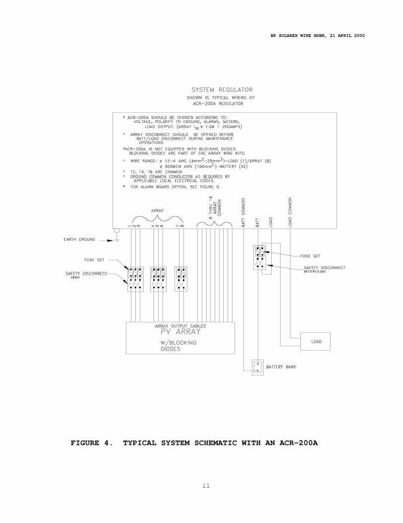
2.9 Typical System Wiring. Typical system wiring using an
ACR-II/30A, an ACR-II/90A, and an ACR-200A are illustrated in Figures 2 thru 4.

BP SOLAREX WIRE HDBK, 21 APRIL 2000
9
FIGURE 2. TYPICAL SYSTEM SCHEMATIC WITH AN ACR-II/30A

BP SOLAREX WIRE HDBK, 21 APRIL 2000
10
FIGURE 3. TYPICAL SYSTEM SCHEMATIC WITH AN ACR-II/90A
BP SOLAREX WIRE HDBK, 21 APRIL 2000
11
FIGURE 4. TYPICAL SYSTEM SCHEMATIC WITH AN ACR-200A

BP SOLAREX WIRE HDBK, 21 APRIL 2000
12
FIGURE 5 3.0 PROCEDURES FOR ARRAY WIRING It is recommended that the following steps be followed when wiring the array.
- - - - - - - - - W A R N I N G - - - - - - - - - Whenever modules are exposed to light, they will generate electricity. Harmful or lethal voltages can be achieved. 1. Refer to the appropriate drawings for the specific voltage and array configuration that you are installing. For wiring Solarstate SRX-XX Regulator, use the Instruction Sheet supplied with the regulator. 2. Remove the modules from the packing boxes. Lay the packing boxes on the ground and then place the modules face down on top of the box in the position that the panels will be racked.

BP SOLAREX WIRE HDBK, 21 APRIL 2000
13
3. Using drawing WKS206*** through WKS248***, locate the specified array configuration. Check all parts using “Parts Terminology” detail for identification. Using the corresponding dash (-) number on the drawing chart, locate appropriate wiring detail. Be sure to read the Wiring Instructions carefully before beginning any wiring. 4. After all module junction boxes (J-box) have been wired in accordance with the system specific wiring directions, start at the end J-box and check to insure that all connections are tight.
C A U T I O N Do not connect the array to the regulator, battery, or load at this time. 5. Refer to the manufactures procedures for the battery and regulator wiring. After the battery and regulator/load are wired, connect the system in the following order: a) Connect the Regulator to the Battery b) Connect the Regulator to the Array Output c) Connect the Load to the Regulator 6. When single conductor wires of the same color (both black or both gray) are used as an output cable, the negative and positive polarities should be clearly identified. A simple way of doing this is to “Tag” the positive wire with one ring of electrical tape at both ends and the negative wire with two rings of electrical tape at both ends (use a different color tape than the wire insulation).

BP SOLAREX WIRE HDBK, 21 APRIL 2000
14
3.1 Recommended Wiring Color Use. a. For 2-conductor cable with black and white conductors,
use Black as Positive and White as Negative. b. For multiple single conductors, Red is Positive, Black is
Negative, and White is the series connection wire. c. Red or Brown should be used primarily for Positive
polarity. Green, Yellow, Green with yellow stripes, or bare copper wire is generally used as a ground wire.
3.2 Grounding (If Applicable). Grounding kits are available as optional additions to a system. Included in these kits are three 1/2-inch x 8-foot ground rods with five clamps for a basic system. Kits are also available for additional rows with two rods and three clamps. Solarex recommends the use of #2 AWG (35 mm2), stranded, bare copper wire. Length of the ground wire must be calculated by size of the system and distance of equipment. Panel grounding clamps are used to ground each individual panel.
Solarex 60 series modules are listed by and have obtained a Class C Fire Rating from Underwriters Laboratories. Supplied with each module is the proper hardware to ensure a positive ground for each module. It is recommended to use #10 AWG (6 mm2) stranded, bare copper wire to connect each module of the panel. However, when using Solarex style panel mounting kits, it may not be necessary to ground tie each individual module because the aluminum structure of the panel is an effective alternative.

BP SOLAREX WIRE HDBK, 21 APRIL 2000
APPENDIX A
AMERICAN/METRIC WIRE GAUGES
The approximate equivalency between American Wire Gauge (AWG) and Metric Wire sizes are shown in the following table.
AWG (#)
METRIC mm2
18 1.0 16 1.5 14 2.5 12 4 10 6 8 10 6 15 4 25 2 35 1/0 50 2/0 70 4/0 105
250 MCM 125 300 MCM 150
NOTE: The Metric equivalent normally represents the next size
up in selection. This means the voltage drop using the metric equivalent of the specified AWG would be lowered e.g., #4 AWG cross section is 20.7mm2 vs. 25mm2 as shown above.
A-1

BP SOLAREX WIRE HDBK, 21 APRIL 2000
VOLTAGE DROP FOR 10 AMP CURRENT AT 100 FOOT DISTANCE
The following table shows the voltage drop (∆ V) occurring in a
cable of the specified gauge carrying a current of 10A for a distance of 100 feet (two wires, each 100 feet) at 75ºC.
AWG (#)
V (V)
18 16.90 16 10.58 14 6.52 12 4.10 10 2.58 8 1.62 6 1.02 4 0.64 2 0.40 1/0 0.25 2/0 0.20 4/0 0.13
250 MCM 0.11 300 MCM 0.09
IMPORTANT Keep the voltage drop to a minimum to ensure proper
operation of the system.
A-2

BP SOLAREX WIRE HDBK, 21 APRIL 2000
APPENDIX B REPLACEMENT PARTS ORDERING INFORMATION Array Parts Part No. Add-On Terminal Kit WK2ATK Diode, Blocking (6V, 12V, 24V) WK2BD-40 Diode, Blocking (24V, 48V, 96V, 200V) WK2BD-400 Diode, 6A, 1000V (200V+) 22200004 Diode, Bypass WK2BPD Intermodule Wire Kit (N.E.C. compliant) WK2IMBRW Interpanel Wire Kit (N.E.C. compliant) WK2IPBR Termination, Output Kit WK2OUTK Offset Lug Terminal Kit WK2OLC Cabling (AWG) #10-2 SEO, Stranded, Bulk 22210006 #10-2 SEO, Stranded, 15 ft. Kit WK2SEO1015F #10-2 SEO, Stranded, 25 ft. Kit WK2SEO1025F #10-1 USE/UF, Stranded, Bulk 22210007 #6-1 USE/UF, Stranded, Bulk 22210001 #4-1 USE/UF, Stranded, Bulk 22210000 #2-1 USE/UF, Stranded, Bulk 22210002 #1/0-1 USE/UF, Stranded, Bulk 22210005 #4/0-1 USE/UF, Stranded, Bulk 22210010 Connectors * Pg 13.5, Nylon, 0.19 - 0.35 28421405 1/2 NPT, Nylon, 0.125 - 0.375 28421408 1/2 NPT, Nylon, 0.310 - 0.560 28421406 1/2 NPT, Metallic, 0.50 - 0.75 22220050 1/2 NPT, Nylon, 0.50 - 0.80 28421389 3/4 NPT, Nylon, 0.50 - 0.75 2700853 3/4 NPT, Metallic, 0.72 - 0.88 22220120 1" NPT, Nylon, 0.70 - 0.95 2700872 *"Pg" hub threads are conduit threads per DIN 40430.
B-1

BP SOLAREX WIRE HDBK, 21 APRIL 2000
Terminals Battery Lug #14-4 AWG, 1/4 Bolt 23501103 Battery Lug #4-2/0 AWG, 3/8 Bolt 23501102 Grounding Bare Copper Cable, #10 AWG, Stranded 31260000 Bare Copper Cable, #2 AWG, Stranded 31260005 Ground Rod, Copper plate, 1/2" x 8' 31260009 Ground Rod Clamp 31260003 Grounding Terminal, #1/0-14 AWG, Panel 23501105
B-2

LEGEND
R=RED (POSITIVE)B=BLACK (NEGATIVE)W=WHITE (SERIES)
CONSENT OF BP SOLAREX OR AN AUTHORIZED AGENT.MANUFACTURE OR DISCLOSED WITHOUT PRIOR
NOT BE COPIED (IN WHOLE OR IN PART) USED FORTHIS DRAWING IS PROPERTY OF BP SOLAREX AND MAY
THIRD ANGLE PROJECTION
FINISH:
MATERIAL:
S
DO NOT SCALE THIS DRAWING
DRAWING NUMBER:LINEAR DIMENSIONS OR DIAMETER DIMENSIONS
UNLESS OTHERWISE SPECIFIED, DIMENSIONS: mm [INCHES]PRIMARY DIMS ARE MILLIMETERS, INCH DIMS FOR REFERENCE ONLY
± 0.3
30 - 1206 - 300.5 - 6PREVIOUS DRAWING NO.
± 0.1 ± 0.2
3/22/93PART NO.:
DRAWN
DATE
1000-2000315-1000120 - 315
± 0.5 ± 0.8 ± 1.2
APPROVEDCHECKED
BP MARYLAND, U.S.A.
WKS206***SCALE: SHEET OF1 1
X
6V BASIC WIRINGSYSTEMS
AL RE
REV
BP SOLAREX
DESCRIPTION OF CHANGELTR ECO NO.
REVISIONS
CHANGED BY / DATE
ANONE
NOTES: READ CAREFULLY
3- LENGTH OF OUTPUT CABLE IN THE CHART IS THE MAXIMUM 'ELECTRICAL' DISTANCE FOR THE SYSTEM. THIS LENGTH IS THE SUM OF THE POSITIVE WIRE LENGTH AND THE NEGATIVE WIRE LENGTH. LENGTHS LESS THAN THE MAXIMUM ARE ACCEPTABLE. FOR U.S.E. TYPE CABLES (SINGLE CONDUCTOR) (2 EA.) CUT LENGTH OF ONE HALF OF THE SPECIFIED DISTANCE ARE REQUIRED. 'NOT TO EXCEED VOLTAGE DROP USED: 0.12V. VOLTAGE DROP CALCULATIONS USED pp FOR SX-64 (7.32A) AND COPPER WIRE RESISTANCE AT 75°C.
4- IT IS RECOMMENDED THAT ALL CONNECTIONS BE CHECKED AND RE-TIGHTENED SOMETIME AFTER INITIAL INSTALLATION.
1- INTERMODULE KITS ARE SUPPLIED WITH 3 WIRES; RED (+), BLACK (-), WHITE (SERIES). ALL WIRES MAY NOT BE REQUIRED, DEPENDING ON THE SYSTEM ORDERED. WHEN WIRING, PLEASE TAKE NOTE OF THE COLORS SPECIFIED AND REMOVE THE EXTRA WIRE FROM THE KIT.
2- MOVE JUMPER LOCATED AT TERMINALS 2 & 3 TO TERMINALS 1 & 2 AND JUMPER AT TERMINALS 4 & 5 TO TERMINALS 5 & 6. LOCATE BLOCKING DIODES AT TERMINALS 2 & 3 AND 4 & 5, AS SHOWN.

LTR DESCRIPTION OF CHANGEECO NO.
REVISIONS
CHANGED BY / DATE
2/8/93
DRAWN
PART NO.:
PRIMARY DIMS ARE MILLIMETERS, INCH DIMS FOR REFERENCE ONLYUNLESS OTHERWISE SPECIFIED, DIMENSIONS: mm [INCHES]
DATE
PREVIOUS DRAWING NO.THIRD ANGLE PROJECTION
FINISH:
MATERIAL:
± 0.1
0.5 - 6
THIS DRAWING IS PROPERTY OF BP SOLAREX AND MAY NOT BE COPIED (IN WHOLE OR IN PART) USED FOR
MANUFACTURE OR DISCLOSED WITHOUT PRIORCONSENT OF BP SOLAREX OR AN AUTHORIZED AGENT.
12V BASIC WIRING
DRAWING NUMBER:
DO NOT SCALE THIS DRAWING
LINEAR DIMENSIONS OR DIAMETER DIMENSIONS
± 0.3± 0.2 ± 0.5
30 - 1206 - 30 120 - 315
± 1.2± 0.8
1000-2000315-1000
NONE
WKS212***
SYSTEMS
SCALE:
ASHEET OF1 1
REV
CHECKED APPROVED
BP AS L ER X BP SOLAREXMARYLAND, U.S.A.
3- LENGTH OF OUTPUT CABLE IN THE CHART IS THE MAXIMUM 'ELECTRICAL' DISTANCE FOR THE SYSTEM. THIS LENGTH IS THE SUM OF THE POSITIVE WIRE LENGTH AND THE NEGATIVE WIRE LENGTH. LENGTHS LESS THAN THE MAXIMUM ARE ACCEPTABLE. FOR U.S.E. TYPE CABLES (SINGLE CONDUCTOR) (2 EA.) CUT LENGTH OF ONE HALF OF THE SPECIFIED DISTANCE ARE REQUIRED. 'NOT TO EXCEED VOLTAGE DROP USED: 0.12V. VOLTAGE DROP CALCULATIONS USED pp FOR SX-64 (7.32A) AND COPPER WIRE RESISTANCE AT 75°C.
2- MOVE JUMPER LOCATED AT TERMINALS 2 & 3 TO TERMINALS 1 & 2 AND JUMPER AT TERMINALS 4 & 5 TO TERMINALS 5 & 6. LOCATE BLOCKING DIODES AT TERMINALS 2 & 3 AND 4 & 5, AS SHOWN.
1- INTERMODULE KITS ARE SUPPLIED WITH 3 WIRES; RED (+), BLACK (-), WHITE (SERIES). ALL WIRES MAY NOT BE REQUIRED, DEPENDING ON THE SYSTEM ORDERED. WHEN WIRING, PLEASE TAKE NOTE OF THE COLORS SPECIFIED AND REMOVE THE EXTRA WIRE FROM THE KIT.
4- IT IS RECOMMENDED THAT ALL CONNECTIONS BE CHECKED AND RE-TIGHTENED SOMETIME AFTER INITIAL INSTALLATION.
NOTES: READ CAREFULLY

SEE NOTE 5.
(OFFSET LUG CONNECTORS NOT REQUIRED)
LTR DESCRIPTION OF CHANGE
REVISIONS
ECO NO. CHANGED BY / DATE
3/22/93
6 - 30
± 0.2
LINEAR DIMENSIONS OR DIAMETER DIMENSIONS
UNLESS OTHERWISE SPECIFIED, DIMENSIONS: mm [INCHES]PRIMARY DIMS ARE MILLIMETERS, INCH DIMS FOR REFERENCE ONLY
MATERIAL:
CONSENT OF BP SOLAREX OR AN AUTHORIZED AGENT.MANUFACTURE OR DISCLOSED WITHOUT PRIOR
NOT BE COPIED (IN WHOLE OR IN PART) USED FORTHIS DRAWING IS PROPERTY OF BP SOLAREX AND MAY
THIRD ANGLE PROJECTION
FINISH:
PREVIOUS DRAWING NO.
± 0.1
0.5 - 6
DATE
PART NO.:
DRAWN
24V BASIC WIRING
S
DO NOT SCALE THIS DRAWING
DRAWING NUMBER:315-1000
± 0.8± 0.3 ± 0.5
30 - 120 120 - 315
± 1.2
1000-2000
CHECKED APPROVED
PB
SYSTEMS
WKS224***SCALE: NONE
ASHEET OF1 1
REV
MARYLAND, U.S.A.RAL EX BP SOLAREX
SCREW & WIRE CLAMP
TERMINAL BLOCK
OFFSET LUG CONNECTOR (NOTE 5) ROTATE TONGUE UPSIDE DOWN AS SHOWN, BEFORE INSTALLING TERMINAL.
3- LENGTH OF OUTPUT CABLE IN THE CHART IS THE MAXIMUM 'ELECTRICAL' DISTANCE FOR THE SYSTEM. THIS LENGTH IS THE SUM OF THE POSITIVE WIRE LENGTH AND THE NEGATIVE WIRE LENGTH. LENGTHS LESS THAN THE MAXIMUM ARE ACCEPTABLE. FOR U.S.E. TYPE CABLES (SINGLE CONDUCTOR) (2 EA.) CUT LENGTH OF ONE HALF OF THE SPECIFIED DISTANCE ARE REQUIRED. 'NOT TO EXCEED VOLTAGE DROP USED: 0.12V. VOLTAGE DROP CALCULATIONS USED pp FOR SX-64 (7.32A) AND COPPER WIRE RESISTANCE AT 75°C.
2- MOVE JUMPER LOCATED AT TERMINALS 2 & 3 TO TERMINALS 1 & 2 AND JUMPER AT TERMINALS 4 & 5 TO TERMINALS 5 & 6. LOCATE BLOCKING DIODES AT TERMINALS 2 & 3 AND 4 & 5, AS SHOWN.
1- INTERMODULE KITS ARE SUPPLIED WITH 3 WIRES; RED (+), BLACK (-), WHITE (SERIES). ALL WIRES MAY NOT BE REQUIRED, DEPENDING ON THE SYSTEM ORDERED. WHEN WIRING, PLEASE TAKE NOTE OF THE COLORS SPECIFIED AND REMOVE THE EXTRA WIRE FROM THE KIT.
4- IT IS RECOMMENDED THAT ALL CONNECTIONS BE CHECKED AND RE-TIGHTENED SOMETIME AFTER INITIAL INSTALLATION.
NOTES: READ CAREFULLY

LTR DESCRIPTION OF CHANGE
REVISIONS
ECO NO. CHANGED BY / DATE
3/22/93
6 - 30
± 0.2
LINEAR DIMENSIONS OR DIAMETER DIMENSIONS
UNLESS OTHERWISE SPECIFIED, DIMENSIONS: mm [INCHES]PRIMARY DIMS ARE MILLIMETERS, INCH DIMS FOR REFERENCE ONLY
MATERIAL:
CONSENT OF BP SOLAREX OR AN AUTHORIZED AGENT.MANUFACTURE OR DISCLOSED WITHOUT PRIOR
NOT BE COPIED (IN WHOLE OR IN PART) USED FORTHIS DRAWING IS PROPERTY OF BP SOLAREX AND MAY
THIRD ANGLE PROJECTION
FINISH:
PREVIOUS DRAWING NO.
± 0.1
0.5 - 6
DATE
PART NO.:
DRAWN
48V BASIC WIRING
S
DO NOT SCALE THIS DRAWING
DRAWING NUMBER:315-1000
± 0.8± 0.3 ± 0.5
30 - 120 120 - 315
± 1.2
1000-2000
CHECKED APPROVED
PB
SYSTEMS
WKS248***SCALE: NONE
ASHEET OF1 1
REV
MARYLAND, U.S.A.RAL EX BP SOLAREX
SCREW & WIRE CLAMP
TERMINAL BLOCK
OFFSET LUG CONNECTOR (NOTE 5) ROTATE TONGUE UPSIDE DOWN AS SHOWN, BEFORE INSTALLING TERMINAL.
3- LENGTH OF OUTPUT CABLE IN THE CHART IS THE MAXIMUM 'ELECTRICAL' DISTANCE FOR THE SYSTEM. THIS LENGTH IS THE SUM OF THE POSITIVE WIRE LENGTH AND THE NEGATIVE WIRE LENGTH. LENGTHS LESS THAN THE MAXIMUM ARE ACCEPTABLE. FOR U.S.E. TYPE CABLES (SINGLE CONDUCTOR) (2 EA.) CUT LENGTH OF ONE HALF OF THE SPECIFIED DISTANCE ARE REQUIRED. 'NOT TO EXCEED VOLTAGE DROP USED: 0.12V. VOLTAGE DROP CALCULATIONS USED pp FOR SX-64 (7.32A) AND COPPER WIRE RESISTANCE AT 75°C.
2- MOVE JUMPER LOCATED AT TERMINALS 2 & 3 TO TERMINALS 1 & 2 AND JUMPER AT TERMINALS 4 & 5 TO TERMINALS 5 & 6. LOCATE BLOCKING DIODES AT TERMINALS 2 & 3 AND 4 & 5, AS SHOWN.
1- INTERMODULE KITS ARE SUPPLIED WITH 3 WIRES; RED (+), BLACK (-), WHITE (SERIES). ALL WIRES MAY NOT BE REQUIRED, DEPENDING ON THE SYSTEM ORDERED. WHEN WIRING, PLEASE TAKE NOTE OF THE COLORS SPECIFIED AND REMOVE THE EXTRA WIRE FROM THE KIT.
4- IT IS RECOMMENDED THAT ALL CONNECTIONS BE CHECKED AND RE-TIGHTENED SOMETIME AFTER INITIAL INSTALLATION.
NOTES: READ CAREFULLY