photoswitch din rail fiber optic amplifier · • selectable pnp and npn output using push button...
TRANSCRIPT
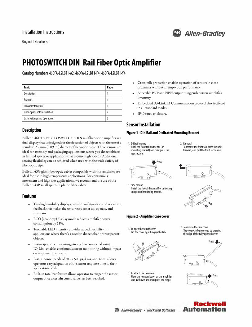
Installation Instructions
Original Instructions
PHOTOSWITCH DIN Rail Fiber Optic AmplifierCatalog Numbers 46DFA-L2LBT1-A2, 46DFA-L2LBT1-F4, 46DFA-L2LBT1-Y4
DescriptionBulletin 46DFA PHOTOSWITCH® DIN rail fiber-optic amplifier is a dual display that is designed for the detection of objects with the use of a standard 2.2 mm (0.09 in.) diameter fiber-optic cable. These sensors are ideal for assembly and packaging applications where you detect objects in limited spaces or applications that require high speeds. Additional sensing flexibility can be achieved when used with the wide variety of fiber-optic tips.
Bulletin 43G glass fiber-optic cables compatible with this amplifier are ideal for use in high temperature applications. For continuous movement and high-flex applications, we recommend the use of the Bulletin 43P small aperture plastic fiber cables.
Features• Two high-visibility displays provide configuration and operation
feedback that makes the sensor easy to set up, operate, and maintain.
• ECO (economy) display mode reduces amplifier power consumption by 25%.
• Teachable LED intensity provides added flexibility in applications where there’s a need to detect clear or transparent objects.
• Fast-response output using pin 2 when connected using IO-Link enables continuous sensor monitoring without impact on response time needs.
• Fast response speeds of 50 µs, 500 µs, 4 ms, and 32 ms allows operators easy adaptation of the sensor response time to their application needs.
• Built-in totalizer feature allows operator to trigger the sensor output once a certain count value has been reached.
• Cross-talk protection enables operation of sensors in close proximity without an impact on performance.
• Selectable PNP and NPN output using push button simplifies inventory.
• Embedded IO-Link 1.1 Communication protocol that is offered in all standard modes.
• IP40 rated enclosure.
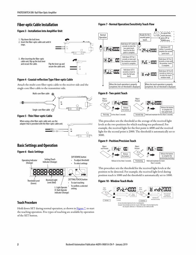
Sensor InstallationFigure 1 - DIN Rail and Dedicated Mounting Bracket
Figure 2 - Amplifier Case Cover
Topic Page
Description 1
Features 1
Sensor Installation 1
Fiber-optic Cable Installation 2
Basic Settings and Operation 2
1. DIN rail mountHook the front tab on the rail (or mounting bracket) and then press the rear section.
2. RemovalTo remove the front tab, press the unit forward, and pull the front section up.
3. Side mountInstall the side of the amplifier unit using an optional mounting bracket.
1. To open the sensor coverLift the cover by pulling up the tab.
2. To remove the case coverThe cover can be removed by pressing the edge of the fully opened cover.
3. To attach the case coverPlace the removed cover on the amplifier unit as shown and then press the hinge.
Press
Press
Press
PHOTOSWITCH DIN Rail Fiber Optic Amplifier
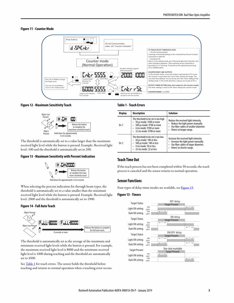
Fiber-optic Cable InstallationFigure 3 - Installation Into Amplifier Unit
Figure 4 - Coaxial-reflection Type Fiber-optic Cable
Attach the multi-core fiber-optic cable to the receiver side and the single-core fiber cable to the transmitter side.
Figure 5 - Thin Fiber-optic Cable
Basic Settings and OperationFigure 6 - Basic Settings
Teach ProcedureHold down SET during normal operation, as shown in Figure 7, to start the teaching operation. Five types of teaching are available by operation of the SET button.
Figure 7 - Normal Operation/Sensitivity Teach Flow
Figure 8 - Two-point Teach
This procedure sets the threshold as the average of the received light levels at the two positions for which teaching was performed. For example, the received light for the first point is 4000 and the received light for the second point is 2000. The threshold is automatically set to 3000.
Figure 9 - Position/Precision Teach
This procedure sets the threshold for the received light levels at the position to be detected. For example, the received light level during position teach is 1000 and the threshold is automatically set to 1000.
Figure 10 - Window Teach Mode
1. Flip down the lock lever.2. Insert the fiber-optic cable unit until it
stops.
3. After inserting the fiber-optic cable unit, flip up the lock lever and secure the cable. Flip the lever up and
secure the cable unit.
Multi-core fiber cable
Single-core fiber cable
When using a thin fiber-optic cable unit, use the adapter that is provided with the fiber-optic cable unit.
L
D
Operating Indicator(Orange)
Setting/Teach Indicator (Orange)
[UP/DOWN] button• To adjust threshold• To select settings
L: Light OperateD: Dark Operateindicator (Orange)
Received LightLevel (Red)
Threshold Level(Green)
[SETTING/TEACH] button• To start teaching• To confirm a selected
setting
NormalOperation
To cancel the teach process, press UP or DOWN once.
When the teach operation is properlycompleted, the set threshold is displayed.
Ready for the second-point
teach.
Hold down SET within 3 seconds to
complete the second-point teach.
Hold down SET for 3seconds or more and
the position teachis complete.
When the teach operation is properlycompleted, the set threshold is displayed.
UP
DOWN
SET
SET
Hold down SET 8 seconds or more to enter the full auto
teach.
Hold down SET within 3seconds to enter the
two-point teach. Teach for the first point is complete.
Hold down SET for 3 seconds or more and
the maximum sensitiv-ity teach is complete.
Hold down SET for 8seconds or more toto enter the teach
window mode.
Object Present
SETSET
ObjectPresent
Releasethe button.
Release the buttonto complete the
two-point teach.First step Second stepIn less than 3 seconds Hold and maintain for less than 3 seconds.
Object not Present
SETSET
ObjectPresent
Releasethe button.
Release the buttonto complete the
positioning teaching.PositioningRelease in less than 3 seconds. Hold and maintain for more
than 3 seconds.
In less than3 secondsFirst Step Second step
ObjectPresent
ObjectPresent
Releasethe button.
Hold down formore than 8 seconds.
Release the buttonto complete the
window mode teach.
Set two thresholds (high/low) for the 2 teaching points.Example: → Received light level for the 1st point: 4000 (high)
the 2nd point: 2000 (low) → Received light level for
Thresholds are set to 4000 and 2000.
2 Rockwell Automation Publication 46DFA-IN001A-EN-P - January 2019

PHOTOSWITCH DIN Rail Fiber Optic Amplifier
Figure 6 - Basic Settings (continued)
D.O.
L.O.
Logic
Pin4
Pin2
L.O.
D.O.
Long 4ms
Super Long 32ms
Detec�on Response �me
High speed 50μs
Standard 500μs
Light Operate/Dark Operate
Normal Opera�on
Dark Operate
Light Operate
Detec�on speed50us: High speed
OFF delay
ON delay
ON/OFF delay
One-shot
500us: Standard
4ms: Long
Press the UP andDOWN bu�ons
Four �mer se�ngs can be selected.Use the bu�on to specify between 1 and 9999 ms in increments of 1ms.The ini�al se�ng is 1 ms.
source level adjustment
The light source intensity can be adjusted both automa�cally and manually.NOTE: The automa�c adjustment sets an op�mum light source intensity at teaching.
Response �me can be selected.
Displays the set �mer mode.
32ms: Super Long
Hysteresis adjustment
Select PNP or NPN.IO-Link connec�on is disabled when NPN is selected.
Move to nextwhen select �mer off.
Auto Manual
Holddown.
Hysteresis can be adjusted between 10 and 2,000.
This se�ng is for Pin 4 output. Pin 2 is setas a complementary output.
Pin 4 Output Type Selec�on.
Timer Off
Light source level adjustment.
OFF delay
Rockwell Automation Publication 46DFA-IN001A-EN-P - January 2019 3

PHOTOSWITCH DIN Rail Fiber Optic Amplifier
Figure 6 - Basic Settings (continued)
standardindica�on
indica�on
Zero offsetindica�on
Rotate Display
Received light levelindica�on
Besides the standard received light level indica�on,the zero offset indica�on and the % indica�on are available.
Select the Counter indica�on to enter the Counter modewhen it returns to Normal Opera�on.
ECO mode
Used to reduce power consump�on.Approx.15 seconds a�er the se�ng, the 7-segment indica�on turns OFF.Pressng any bu�on turns the display on and turns it off again a�er 15 seconds.
Bu�on Opera�on Lock
Reset to Factory Default
Reset sensor se�ngs to factory default.
When the bu�on opera�on lock is set, opera�on of each bu�on is enabled a�er the UPbu�on is held down for approximately six seconds during normal opera�on.When approximately 10 seconds has elapsed without any bu�on opera�on, the bu�onopera�on lock is set again.
Pin 2 Output Type Selec�on.
Select PNP, NPN, or OFF (Output is disabled)
Counter Indica�on
4 Rockwell Automation Publication 46DFA-IN001A-EN-P - January 2019
PHOTOSWITCH DIN Rail Fiber Optic Amplifier
Figure 11 - Counter Mode
Figure 12 - Maximum Sensitivity Teach
The threshold is automatically set to a value larger than the maximum received light level while the button is pressed. Example: Received light level: 100 and the threshold is automatically set to 200.
Figure 13 - Maximum Sensitivity with Percent Indication
When selecting the percent indication for through beam types, the threshold is automatically set to a value smaller than the minimum received light level while the button is pressed. Example: Received light level: 2000 and the threshold is automatically set to 1900.
Figure 14 - Full Auto Teach
The threshold is automatically set as the average of the maximum and minimum received light levels while the button is pressed. For example, the maximum received light level is 8000 and the minimum received light level is 1000 during teaching and the threshold are automatically set to 4500.
See Table 1 for teach errors. The sensor holds the threshold before teaching and returns to normal operation when a teaching error occurs.
Table 1 - Teach Errors
Teach Time OutIf the teach process has not been completed within 30 seconds, the teach process is canceled and the sensor returns to normal operation.
Sensor FunctionsFour types of delay timer modes are available, see Figure 15.
Figure 15 - Timers
IO-Link Communica�on Index: 101 “Counter Indica�on”
Counter mode(Normal Opera�on)
Press bu�ons
Target count indica�on for 5 seconds
Count Value
Count Value"Counter Mode" indica�on for 2 seconds
Standard indica�on appears while pressing SET.
Press UP or DOWN to changethe Target count.
Press the UP and DOWN toreturn to the “Se�ng mode.”
TO TEACH OR SET THRESHOLD LEVEL IO-Link Communica�on
Teaching or threshold se�ng can be conducted by Service Func�on Command or Index 60.
Strandard I/O Return to the Se�ng mode, go to Received light level indica�on and
select Standard indica�on. Then teaching can be conducted asdescribed in 5-2 Teaching. Threshold can be adjusted by pressingUP or DOWN bu�on.
COUNTER RESET AND OUTPUTS In the Counter mode, a one-shot output is generated on Pin 4 and the counter is reset when the count value reaches the target. Theone-shot �me (default: 10 ms) can be set in the Timer se�ng of the Se�ng mode. In SIO mode detec�on, outputs are issued on Pin 2.
OUTPUT TIMER SETTING (One-shot output for the Counter mode) The �mer se�ng is reset to OFF when exi�ng the counter mode.
COUNTER RANGE: 1 to 9999+Hold down SET and DOWN for 5 seconds to rest the Counter.
Object notPresent
SET
Release the buttonto complete the
maximum sensitivity teach.Hold down for approximately
3 to 8 seconds.
ObjectPresent
SET
Release the buttonto complete the maxi-mum sensitivity teach.
Hold down for approximately 3 to 8 seconds
Object Present
SET
Object not PresentRelease the button to complete
the full auto teach.8 seconds or more
Display Description Solution
Err 1
The threshold to be set is too high.• 50 µs mode: 3500 or more• 500 µs mode: 9700 or more• 4 ms mode: 9700 or more• 32 ms mode: 9700 or more
Reduce the received light intensity.• Reduce the light power manually.• Use fiber cables of smaller diameter.• Detect at longer range.
Err 2
The threshold to be set is too low.• 50 µs mode: 100 or less• 500 µs mode: 180 or less• 4 ms mode: 50 or less• 32 ms mode: 22 or less
Increase the received light intensity.• Increase the light power manually.• Use fiber cables of larger diameter.• Detect at shorter range.
Target Present
Target Status
Light ON setting
Dark ON setting
Target Status
Light ON setting
Dark ON setting
Target Status
Light ON setting
Dark ON setting
Target Present
Light ON setting
Dark ON setting
OFF delay
ON delay
ON/OFF delay
ONOFFON
OFF
ONOFFON
OFF
ONOFFON
OFF
ONOFFON
OFF
T
T
T
T
T
T
T
T
T
T
Target Present
Target Present
Target Present
One-shot resettable
Rockwell Automation Publication 46DFA-IN001A-EN-P - January 2019 5

PHOTOSWITCH DIN Rail Fiber Optic Amplifier
Received Light Level IndicationThree types of indication are available for the received light level and threshold.
Standard Indication
The direct values of received light level and threshold are displayed without correction.
Figure 16 - Standard Indication
Percent Indication
The received light level and threshold are displayed in percent as the maximum received light level during teaching is set to 100. The same displayed values can be arranged when multiple through-beam type units are in use.
This display may not be arranged at 100 as the received light intensity varies depending on environmental factors.
Figure 17 - Percentage Indication
Figure 18 - Zero Offset Indication
Differential value is displayed in the received light level and threshold as the minimum value of the received light level during teaching is set to zero. The same displayed values can be arranged when multiple reflective-type units are in use.
Figure 19 - Percent and Zero Offset Indication Examples
Crosstalk AvoidanceThe sensor offers an optical unit-to-unit crosstalk avoidance feature when multiple amplifiers are operating in close proximity. To enable this function, the Bulletin 46DFA amplifier must be installed side-by-side and as close as possible in the DIN rail. To be sure there’s a reliable crosstalk avoidance, we recommend that you use the DIN rail stop catalog number 60-BDFA-STP to firmly secure the units. This feature is disabled when the sensor is set to operate in 50 µs mode.
Figure 20 - DIN Rail Stop Catalog Number 60-BDFA-STP
The received light level is displayed as a percentage because the maximum received light level during teaching is set to 100.
During teaching (the received light level is displayed).
No object isdetected
An object isdetected
Each received light level after teachingis displayed as below.
Two-point teachingreceived light level
for the second point: 1000
Two-point teachingreceived light level
for the first point: 5000
In the percentage indication:
Displays as a percentage.Maximum value duringteaching is set to 100.
Zero offset indicationDifferential value (displayed as the minimum received light level during teaching) is set to zero.
Two-point teachingreceived light level
for the second point: 100
Two-point teachingreceived light level
for the first point: 555
Each received light level after teachingis displayed as below.
Displays zero for theminimum valueduring teaching.
Displays thedifferential
value from zero.
Percentage Indication
60-BDFA-STP
6 Rockwell Automation Publication 46DFA-IN001A-EN-P - January 2019
PHOTOSWITCH DIN Rail Fiber Optic Amplifier
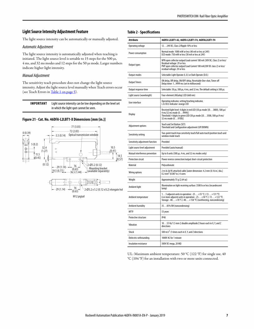
Light Source Intensity Adjustment FeatureThe light source intensity can be automatically or manually adjusted.
Automatic Adjustment
The light source intensity is automatically adjusted when teaching is initiated. The light source level is settable to 15 steps for the 500 µs, 4 ms, and 32 ms modes and 12 steps for the 50 µs mode. Larger numbers indicate higher light intensity.
Manual Adjustment
The sensitivity teach procedure does not change the light source intensity. Adjust the light source level manually when Teach errors occur (see Teach Errors in Table 1 on page 5).
Figure 21 - Cat. No. 46DFA-L2LBT1-X Dimensions [mm (in.)]
UL: Maximum ambient temperature: 50 °C (122 °F) for single use, 40 °C (104 °F) for an installation with two or more units connected.
IMPORTANT Light source intensity can be low depending on the level set in which the light spot cannot be seen.
0 (0.39)
5 (0.2)
11.5(0.45)
3(0.12)
3.5 (0.14)
19.5 (0.77)16
(0.63)
2-Ø 3.2 x 5.2 (0.12 x 0.2) elongate hole
Mounting bracket (available separately)
2-Ø3.2 (0.12)
Optical transmission window
14.5(0.57)
10.5(0.41)
29 (1.14)
32.4(1.27)
72 (2.83)77 (3.03)
29 (1.14)
36.5 (1.44)
16(0.63)
M12 pigtail
Table 2 - Specifications
Attribute 46DFA-L2LBT1-A2, 46DFA-L2LBT1-F4, 46DFAL2LBT1-Y4
Operating voltage 12…24V DC, Class 2/Ripple 10% or less
Power consumption Normal mode: 1000 mW or less (40 mA or less at 24V)ECO mode: 750 mW or less (30 mA or less at 24V)
Output types
NPN open collector output/Load current 100 mA (30V DC, Class 2) or less/Residual voltage: 2V or lessPNP open collector output/Load Current 100 mA(30V DC class 2) or less/ residual voltage: 2V or less
Output modes Selectable Light Operate (L.O.) or Dark Operate (D.O.)
Output Timers ON delay, Off delay, ON/OFF delay, Resettable One-shot, Timer offDelay timer: 1...9999 ms (set in millisecond)
Output response time Selectable: 50 µs, 500 µs, 4 ms, and 32 ms. The default setting is 500 µs.
Light source (wavelength) Four-element (AlGaInp) LED (660 nm)
User interface Operating indicator, setting/teaching indicator, L.O./D.O. Indicator: orange LED
Display
Received light level: 4 digits in red LED (50 µs mode [(0…3800), 500 μs/4 ms/32 ms mode (0…9999)]Threshold: 4 digits in green LED (50 µs mode [(0…3500, 500 μs/4 ms/32 ms mode (0…9700)]
Adjustment options Teach and Set Button (SET)Threshold and Configuration adjustment (UP/DOWN)
Sensitivity setting Two-point teach/max sensitivity teach/full auto teach/position teach and window mode teach
Sensitivity adjustment function Provided
Light source level adjustment Provided (auto/manual)
Mutual interference prevention Up to 8 units (500 μs, 4 ms, and 32 ms modes only)
Protection circuit Power reverse connection/output short-circuit protection
Material Polycarbonate
Wiring options 2 m (6.56 ft) attached cable [outer dimension: 4.2 mm (0.16 in.) dia.] 0.2 mm2 (0.007 in.) 4 cores
Weight Approximately 75 g (2.64 oz)
Ambient light Illumination on light receiving surface: 3500 lx or less (incandescent lamp)
Ambient temperature1…5 adjacent units in operation: -25…+55 °C (-13…+131 °F)6 or more adjacent units in operation: -25…+50 °C (-13…+122 °F)Storage: -40…+70 °C (-40…+158 °F) (nonfreezing, noncondensing)
Ambient humidity 35…85% RH (noncondensing)
MTTF 53 years
Protective structure IP40
Vibration 10…55 Hz/1.5 mm () double amplitude/2 hours each in X, Y, and Z directions
Shock 500 m/s2 /3 times each in X, Y, and Z directions
Dielectric withstanding 1000V AC for 1 minute
Insulation resistance 500V DC mega, 20 MΩ
Rockwell Automation Publication 46DFA-IN001A-EN-P - January 2019 7
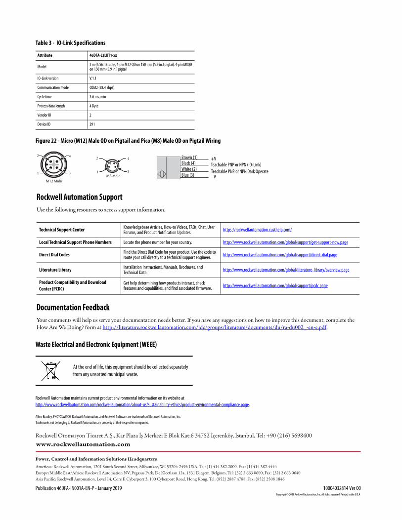
Figure 22 - Micro (M12) Male QD on Pigtail and Pico (M8) Male QD on Pigtail Wiring
Rockwell Automation SupportUse the following resources to access support information.
Documentation FeedbackYour comments will help us serve your documentation needs better. If you have any suggestions on how to improve this document, complete the How Are We Doing? form at http://literature.rockwellautomation.com/idc/groups/literature/documents/du/ra-du002_-en-e.pdf.
Technical Support Center Knowledgebase Articles, How-to Videos, FAQs, Chat, User Forums, and Product Notification Updates. https://rockwellautomation.custhelp.com/
Local Technical Support Phone Numbers Locate the phone number for your country. http://www.rockwellautomation.com/global/support/get-support-now.page
Direct Dial Codes Find the Direct Dial Code for your product. Use the code to route your call directly to a technical support engineer. http://www.rockwellautomation.com/global/support/direct-dial.page
Literature Library Installation Instructions, Manuals, Brochures, and Technical Data. http://www.rockwellautomation.com/global/literature-library/overview.page
Product Compatibility and Download Center (PCDC)
Get help determining how products interact, check features and capabilities, and find associated firmware. http://www.rockwellautomation.com/global/support/pcdc.page
Waste Electrical and Electronic Equipment (WEEE)
Table 3 - IO-Link Specifications
Attribute 46DFA-L2LBT1-xx
Model 2 m (6.56 ft) cable, 4-pin M12 QD on 150 mm (5.9 in.) pigtail, 4-pin M8QD on 150 mm (5.9 in.) pigtail
IO-Link version V.1.1
Communication mode COM2 (38.4 kbps)
Cycle time 3.6 ms, min
Process data length 4 Byte
Vendor ID 2
Device ID 291
At the end of life, this equipment should be collected separately from any unsorted municipal waste.
3
2
1
4
M12 Male
3
2
1
4
M8 Male
Brown (1)
White (2)Black (4)
Blue (3)
+V
–V
Teachable PNP or NPN (IO-Link)Teachable PNP or NPN Dark Operate
Allen-Bradley, PHOTOSWITCH, Rockwell Automation, and Rockwell Software are trademarks of Rockwell Automation, Inc.
Trademarks not belonging to Rockwell Automation are property of their respective companies.
Rockwell Otomasyon Ticaret A.Ş., Kar Plaza İş Merkezi E Blok Kat:6 34752 İçerenköy, İstanbul, Tel: +90 (216) 5698400
Rockwell Automation maintains current product environmental information on its website athttp://www.rockwellautomation.com/rockwellautomation/about-us/sustainability-ethics/product-environmental-compliance.page.
Publication 46DFA-IN001A-EN-P - January 2019 10004032814 Ver 00Supersedes Publication xxxx-INxxxx-EN-P - Month Year Copyright © 2019 Rockwell Automation, Inc. All rights reserved. Printed in the U.S.A.